EP2343784A1 - Portable storage device - Google Patents
Portable storage device Download PDFInfo
- Publication number
- EP2343784A1 EP2343784A1 EP10170368A EP10170368A EP2343784A1 EP 2343784 A1 EP2343784 A1 EP 2343784A1 EP 10170368 A EP10170368 A EP 10170368A EP 10170368 A EP10170368 A EP 10170368A EP 2343784 A1 EP2343784 A1 EP 2343784A1
- Authority
- EP
- European Patent Office
- Prior art keywords
- cable
- receiving slot
- storage device
- portable storage
- opening
- Prior art date
- Legal status (The legal status is an assumption and is not a legal conclusion. Google has not performed a legal analysis and makes no representation as to the accuracy of the status listed.)
- Withdrawn
Links
- 238000005452 bending Methods 0.000 claims abstract description 19
- 230000005540 biological transmission Effects 0.000 description 3
- 238000010586 diagram Methods 0.000 description 3
- 238000000113 differential scanning calorimetry Methods 0.000 description 2
- 230000001419 dependent effect Effects 0.000 description 1
- 230000009977 dual effect Effects 0.000 description 1
- 238000005516 engineering process Methods 0.000 description 1
- 238000001746 injection moulding Methods 0.000 description 1
- 238000012986 modification Methods 0.000 description 1
- 230000004048 modification Effects 0.000 description 1
- 230000003287 optical effect Effects 0.000 description 1
- 239000007787 solid Substances 0.000 description 1
Images



Classifications
-
- H—ELECTRICITY
- H01—ELECTRIC ELEMENTS
- H01R—ELECTRICALLY-CONDUCTIVE CONNECTIONS; STRUCTURAL ASSOCIATIONS OF A PLURALITY OF MUTUALLY-INSULATED ELECTRICAL CONNECTING ELEMENTS; COUPLING DEVICES; CURRENT COLLECTORS
- H01R13/00—Details of coupling devices of the kinds covered by groups H01R12/70 or H01R24/00 - H01R33/00
- H01R13/72—Means for accommodating flexible lead within the holder
Definitions
- the invention relates to a portable electronic device, and more particularly, to a portable storage device.
- a conventional storage device 1 comprises a hard disk 11 and a body 12.
- the hard disk 11 is disposed in the body 12.
- the storage device 1 has a cable 13 with a connector 131 (e.g. a universal serial bus, USB) to connect with an external electronic device (such as a computer, not shown) for digital data transmission.
- a connector 131 e.g. a universal serial bus, USB
- the cable 13 is linear and extends from the conventional storage device 1, thus, the cable 13 is bound to be detached therefrom or wound on the body 12 while the storage device 1 is not used.
- dealing with the cable matter can be tedious and inconvenient, and the cable may occupy too much space.
- the present invention provides a portable storage device, which may store a cable in a body, thereby avoids space occupation or damage to the cable, furthermore, presents a neat appearance of the portable storage device.
- the portable storage device in accordance with present invention comprises a body and a cable.
- the body has a storing unit and a receiving slot with an opening formed thereon.
- the cable is connected with the body and extendable from the opening of the receiving slot, which is non-circular in cross section and has at least one bending portion.
- the bending portion of the cable is bent with an included angle less than 90 degree.
- the cable has one bending portion in a "U” shape or a "V" shape when extended.
- the cable has multiple bending portions, the cable is in a waved shape, a zigzag shape or the like.
- the bending portion is flexible/resilient and provides a flexibility to extend the cable from the receiving slot of the body when free from latching.
- While storing the cable a user may fold and retract the cable along a longitudinal extension axis, and eventually store it in the receiving slot completely.
- multiple sections of the cable are arranged and may be stacked in a plane along the longitudinal extension axis. Thereby the sections may be received completely in the receiving slot of the body. Furthermore, a latch of the cable may engage a detent formed on the body to retain the cable in the receiving slot. When the cable is used, the user may detach the cable, then, extends the cable by flexibility of itself and then drawing and dragging the cable.
- a cap is provided to cover the opening to position the cable and avoid infringement of external object.
- the receiving slot is accommodated to the folded cable and thus allows the cable be completely stored in the receiving slot to ensure a neat appearance of the portable storage device.
- the portable storage device in accordance with present invention is effectively avoid extra space occupation.
- the cable can be extended along a longitudinal extension axis and the sections thereof can be expanded in a plane.
- Fig. 1 is a sketch diagram showing a conventional portable storage device
- Fig. 2A is a perspective view showing the portable storage device is used
- Fig. 2B is a perspective view of the portable storage device in 2A illustrating a folded cable
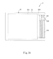
- Fig. 3A is a perspective view of the portable storage device in 2A showing a protruding portion
- Fig. 3B is a perspective view of the portable storage device in 2A showing a cap
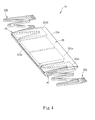
- Fig. 4 is a sketch diagram showing a further embodiment of the portable storage device in accordance with present invention.
- FIGs. 2A and 2B are sketch diagrams of the portable storage device in accordance with a preferred embodiment of present invention.
- Fig. 2A illustrates an unfolded status
- Fig. 2B illustrates a folded status.
- the portable storage device 2 in accordance with present invention comprises a body 21 and at least one cable 22.
- the portable storage device 2 mentioned in the present invention may be any kind of electronic device that is configured to complete an electrical connection via a cable, such as portable hard drives, portable Optical Disc Drives, electronic dictionaries, e-Books, hand-held PCs, Ultra Mobile PC (UMPC), Tablet Personal Computers, Differential scanning calorimetrys (DSC), Digital Videos (DV), Game devices, GPS devices or mobile phones.
- the body 21 has a storing unit 211 that may be Hard Disk Drive (HDD) or Solid State Drive (SSD) built therein.
- the body 21 has a space S1 formed therein to receive the storing unit 211.
- the body 21 has at least one receiving slot 210.
- the receiving slot 210 is formed in at least one side P1 of the body 21 and is communicated with the space S1.
- one receiving slot 210 is formed in the body 21.
- the receiving slot 210 is formed on the right-hand side of the body 21 and has an opening 210a and a detent 210b formed adjacent to the opening 210a.
- An end of the cable 22 is connected with the storing unit 211, and the other end of the cable 22 is adapted to connect to external electronic devices.
- the cable 22 is stored in the receiving slot 210 after being folded, and the receiving slot 210 is accommodated to the folded cable 22 and thus allows the cable 22 to be completely stored in the receiving slot 210 to present a neat appearance. Thereby the cable 22 is completely stored in the receiving slot 210 of the body 21 and extra space occupation is effectively avoided.
- the cable 22 has multiple sections that are arranged and may be stacked in a plane along a longitudinal extension axis (not shown). Thereby the cable 22 can be extended along the longitudinal extension axis and the sections thereof can be expanded in a plane. With such, during drawing and dragging the cable 22 for connection, non-linear twist would not occur on the cable 22. Therefore, the users don't have to neaten the cable 22 at first, and a convenient handling is thus provided.
- the cable 22 is non-circular in cross section, and may have e.g. a rectangular, elliptic, triangular cross-section and the like. As shown in Fig 2A , the cable 22 is mounted in the receiving slot 210 and may be formed via injection molding means or die castling means, wherein said means are included but not limited thereto.
- the cable 22 has at least one bending portion T.
- the cable 22 is in a "U” shape or a "V" shape when extending.
- the cable 22 is in a waved shape, a zigzag shape or the like.
- the bending portion T is flexible and/or resilient and provides a flexibility to extend the cable 22 from the opening 210a of the receiving slot 210 of the body 21 1 when free from latching.
- the cable 22 has multiple bending portions T, each of the bending portions T is bent in an included angle ⁇ less than 90 degree.
- a cross section C of the cable 22 is rectangular, and the cable 22 includes a connector 221 and a wire 222.
- the connector 221 is adapted to connect an external electronic device (not shown) and may be e.g. a USB, RS-232, IEEE-1394 or SATA connector.
- the connector 221 is selectively a USB connector with shell removed.
- Aforementioned detent 210b of the receiving slot 210 corresponds to and engages the connector 221 of the cable 22.
- the wire 222 has two ends which connect respectively to the connector 221 and the storing unit 211.
- the cable 22 is in a zigzag shape when extending.
- a width d2 in the bending portion T of the cable 22 is larger than a width d1 in a linear portion of the wire 222.
- practical embodiments are not limited thereto. With the width d2 being larger than a width d1, the flexibility of the cable 22 is then increased.
- the wire 222 is adjacent to the opening 210a, and the connector 221 is mounted in the detent 210b of the opening 210a of the receiving slot 210 to secure the wire 222 and ensure a complete storing of the cable 22 that keeps in a neat appearance.
- the receiving slot 210 may further have a securing portion.
- the securing portion may be formed in the opening 210a and/or the detent 210b, which engages and secures the connector 221 of the cable 22 folded. Structurally, the securing portion may have a convex or rough surface to provide a friction or positioning.
- the securing portion may also be formed in the receiving slot 210 and may corresponds to and secure with a latch of the cable 22.
- the securing portion and the latch may have corresponding convex surface/concave surface, or rough surfaces to achieve the object of positioning.
- the cable 22 has at least one protruding portion 223.
- the protruding portion 223 protrudes from the opening 210a of the receiving slot 210 while the cable 22 is folded and received in the receiving slot 210, such that a user may detach the connector 221 from the securing portion by pushing the protruding portion 223. Then the cable 22 ejects and extends via flexibility of itself for usual usage.
- the protruding portion 223 is disposed adjacent to the connector 221, practical implementations are not limit thereto.
- a cap 210c is mounted in the opening 210a of the receiving slot 210, thereby to position the cable 22 and avoid infringement of external object.
- an electronic device may transmit digital data with the storing unit 211 of the portable storage device 2 via the cable 22.
- the cable 22 is received and secured in the receiving slot 210.
- the cable 22 is extending along the longitudinal extension axis and the sections thereof are expanding in a plane. Therefore, non-linear twist or curl will not occur on the cable 22.
- the portable storage device may also have two cables disposed in opposite sides of the body. With such dual cable design, power supplying and data transmission speed is improved.
- the portable storage device 2a has two storing unit 211 a disposed in a space S2 of the body 21 a; and the body has two receiving slots 21 al and 21 a2 to receive two cables 22a and 22b, respectively.
- the receiving slots 21 al and 21a2 are formed in two sides P1 and P2 of the body.
- the cables 22a and 22b are connected in the receiving slots 21 al and 21 a2 for digital data transmission.
- the storing unit 211a, 211 b, body 21a, receiving slot 21al, 2 1 a2 and cable 22a, 22b are functionally and structurally similar to the same components of above described embodiment, thus any further illustration thereabout shall not need to be made.
- the portable storage device in accordance with present invention with multiple bending portions that is bent and defines included angles less than 90 degree, subdues the cable to extend along a longitudinal axis in a plane. Therefore, the cable can be easily retracted and stored in the receiving slot, without non-linear twist occurring on the cable. Since the cable is completely stored in the receiving slot, a neat appearance of the portable storage device is thus guaranteed.
Landscapes
- Insertion, Bundling And Securing Of Wires For Electric Apparatuses (AREA)
- Casings For Electric Apparatus (AREA)
Abstract
A portable storage device includes a body and a cable. The body has a receiving slot with an opening. The cable is received in the receiving slot and is electrically connected with the body. The cable has at least one bending portion with an included angle less than 90 degree, thereby flexibly extends the cable along a longitudinal extension axis and avoids non-linear twist or curl occurring on the cable, so as to allow a convenient folding and storing of the connecting cable.
Description
- The invention relates to a portable electronic device, and more particularly, to a portable storage device.
- With highly development of technology, all kinds of electronic products are utilized in people's daily life. Particularly, with demand of light-weight, mini-size and portability, some electronic products, such as digital storage device, are modified to be in a compact structure.
- As shown in
Fig. 1 , aconventional storage device 1 comprises ahard disk 11 and abody 12. Thehard disk 11 is disposed in thebody 12. Except that, thestorage device 1 has acable 13 with a connector 131 (e.g. a universal serial bus, USB) to connect with an external electronic device (such as a computer, not shown) for digital data transmission. - However, as is well known, the
cable 13 is linear and extends from theconventional storage device 1, thus, thecable 13 is bound to be detached therefrom or wound on thebody 12 while thestorage device 1 is not used. However, dealing with the cable matter can be tedious and inconvenient, and the cable may occupy too much space. - What's more, during drawing and dragging the
cable 13 for connection, a non-linear twist (for example, bent in a circular manner, a waved manner or an indirectional manner) is inevitably occurring on thecable 13. With such, a neatening of thecable 13 is necessary, and damage may be easily caused to thecable 13. - It is an object of the present invention to provide a portable storage device that can overcome the above disadvantages of the prior art. This problem is solved by a portable storage device according to
claim 1. Further advantageous embodiments are the subject-matter of the dependent claims. - The present invention provides a portable storage device, which may store a cable in a body, thereby avoids space occupation or damage to the cable, furthermore, presents a neat appearance of the portable storage device.
- The portable storage device in accordance with present invention comprises a body and a cable. The body has a storing unit and a receiving slot with an opening formed thereon. The cable is connected with the body and extendable from the opening of the receiving slot, which is non-circular in cross section and has at least one bending portion. The bending portion of the cable is bent with an included angle less than 90 degree.
- For further illustration, it is provided that the cable has one bending portion in a "U" shape or a "V" shape when extended. On the other hand, provided that the cable has multiple bending portions, the cable is in a waved shape, a zigzag shape or the like. Anyway, it is noted that the bending portion is flexible/resilient and provides a flexibility to extend the cable from the receiving slot of the body when free from latching.
- While storing the cable, a user may fold and retract the cable along a longitudinal extension axis, and eventually store it in the receiving slot completely.
- In Detail, multiple sections of the cable are arranged and may be stacked in a plane along the longitudinal extension axis. Thereby the sections may be received completely in the receiving slot of the body. Furthermore, a latch of the cable may engage a detent formed on the body to retain the cable in the receiving slot. When the cable is used, the user may detach the cable, then, extends the cable by flexibility of itself and then drawing and dragging the cable. Preferably, a cap is provided to cover the opening to position the cable and avoid infringement of external object.
- It is noted, that the receiving slot is accommodated to the folded cable and thus allows the cable be completely stored in the receiving slot to ensure a neat appearance of the portable storage device.
- To sum up, since the cable can be completely stored in the receiving slot of the body, the portable storage device in accordance with present invention is effectively avoid extra space occupation. Moreover, due to the bending portion, according to the present invention the cable can be extended along a longitudinal extension axis and the sections thereof can be expanded in a plane. With such, during drawing and dragging the cable for connection, non-linear twist is not occur on the cable, therefore, the user don't have to neaten the cable at first, and a convenience is then provided.
- These and other features, aspects and advantages of the present invention will become better understood with regard to the following description, appended claims, and accompanying drawings.
- The invention can be more fully understood by reading the following detailed description of the preferred embodiment with reference made to the accompanying drawings as follows:
-
Fig. 1 is a sketch diagram showing a conventional portable storage device; -
Fig. 2A is a perspective view showing the portable storage device is used; -
Fig. 2B is a perspective view of the portable storage device in 2A illustrating a folded cable; -
Fig. 3A is a perspective view of the portable storage device in 2A showing a protruding portion; -
Fig. 3B is a perspective view of the portable storage device in 2A showing a cap; and -
Fig. 4 is a sketch diagram showing a further embodiment of the portable storage device in accordance with present invention. - With reference to
Figs. 2A and2B that are sketch diagrams of the portable storage device in accordance with a preferred embodiment of present invention.Fig. 2A illustrates an unfolded status, andFig. 2B illustrates a folded status. - The
portable storage device 2 in accordance with present invention comprises abody 21 and at least onecable 22. Note that theportable storage device 2 mentioned in the present invention may be any kind of electronic device that is configured to complete an electrical connection via a cable, such as portable hard drives, portable Optical Disc Drives, electronic dictionaries, e-Books, hand-held PCs, Ultra Mobile PC (UMPC), Tablet Personal Computers, Differential scanning calorimetrys (DSC), Digital Videos (DV), Game devices, GPS devices or mobile phones. - The
body 21 has astoring unit 211 that may be Hard Disk Drive (HDD) or Solid State Drive (SSD) built therein. Preferably, thebody 21 has a space S1 formed therein to receive the storingunit 211. - The
body 21 has at least one receivingslot 210. Thereceiving slot 210 is formed in at least one side P1 of thebody 21 and is communicated with the space S1. In the present embodiment, one receivingslot 210 is formed in thebody 21. Thereceiving slot 210 is formed on the right-hand side of thebody 21 and has an opening 210a and a detent 210b formed adjacent to the opening 210a. - An end of the
cable 22 is connected with thestoring unit 211, and the other end of thecable 22 is adapted to connect to external electronic devices. Thecable 22 is stored in thereceiving slot 210 after being folded, and thereceiving slot 210 is accommodated to the foldedcable 22 and thus allows thecable 22 to be completely stored in thereceiving slot 210 to present a neat appearance. Thereby thecable 22 is completely stored in thereceiving slot 210 of thebody 21 and extra space occupation is effectively avoided. - The
cable 22 has multiple sections that are arranged and may be stacked in a plane along a longitudinal extension axis (not shown). Thereby thecable 22 can be extended along the longitudinal extension axis and the sections thereof can be expanded in a plane. With such, during drawing and dragging thecable 22 for connection, non-linear twist would not occur on thecable 22. Therefore, the users don't have to neaten thecable 22 at first, and a convenient handling is thus provided. - The
cable 22 is non-circular in cross section, and may have e.g. a rectangular, elliptic, triangular cross-section and the like. As shown inFig 2A , thecable 22 is mounted in the receivingslot 210 and may be formed via injection molding means or die castling means, wherein said means are included but not limited thereto. - The
cable 22 has at least one bending portion T. For further illustration, provided that thecable 22 has one bending portion T, thecable 22 is in a "U" shape or a "V" shape when extending. On the other hand, provided that thecable 22 has multiple bending portions T, thecable 22 is in a waved shape, a zigzag shape or the like. - The bending portion T is flexible and/or resilient and provides a flexibility to extend the
cable 22 from theopening 210a of the receivingslot 210 of thebody 21 1 when free from latching. In the present embodiment, thecable 22 has multiple bending portions T, each of the bending portions T is bent in an included angle θ less than 90 degree. - In the present embodiment, a cross section C of the
cable 22 is rectangular, and thecable 22 includes aconnector 221 and awire 222. Theconnector 221 is adapted to connect an external electronic device (not shown) and may be e.g. a USB, RS-232, IEEE-1394 or SATA connector. - In the present embodiment, the
connector 221 is selectively a USB connector with shell removed.Aforementioned detent 210b of the receivingslot 210 corresponds to and engages theconnector 221 of thecable 22. Thewire 222 has two ends which connect respectively to theconnector 221 and thestoring unit 211. - As shown in
Fig. 2A , with the included angle θ of the bending portion T being less than 90 degree, thecable 22 is in a zigzag shape when extending. Moreover, in the present embodiment, a width d2 in the bending portion T of thecable 22 is larger than a width d1 in a linear portion of thewire 222. But practical embodiments are not limited thereto. With the width d2 being larger than a width d1, the flexibility of thecable 22 is then increased. - As shown in 2B, when the
cable 22 is received in the receivingslot 210, thewire 222 is adjacent to theopening 210a, and theconnector 221 is mounted in thedetent 210b of theopening 210a of the receivingslot 210 to secure thewire 222 and ensure a complete storing of thecable 22 that keeps in a neat appearance. - The receiving
slot 210 may further have a securing portion. The securing portion may be formed in theopening 210a and/or thedetent 210b, which engages and secures theconnector 221 of thecable 22 folded. Structurally, the securing portion may have a convex or rough surface to provide a friction or positioning. - For further illustration, the securing portion may also be formed in the receiving
slot 210 and may corresponds to and secure with a latch of thecable 22. In practice, the securing portion and the latch may have corresponding convex surface/concave surface, or rough surfaces to achieve the object of positioning. - Additionally, as shown in
Fig. 3A , thecable 22 has at least one protrudingportion 223. The protrudingportion 223 protrudes from theopening 210a of the receivingslot 210 while thecable 22 is folded and received in the receivingslot 210, such that a user may detach theconnector 221 from the securing portion by pushing the protrudingportion 223. Then thecable 22 ejects and extends via flexibility of itself for usual usage. Note that although, in the present embodiment, the protrudingportion 223 is disposed adjacent to theconnector 221, practical implementations are not limit thereto. - Furthermore, as shown in
Fig. 3B , acap 210c is mounted in theopening 210a of the receivingslot 210, thereby to position thecable 22 and avoid infringement of external object. - It is known that an electronic device may transmit digital data with the
storing unit 211 of theportable storage device 2 via thecable 22. When theportable storage device 2 is not used, thecable 22 is received and secured in the receivingslot 210. With features of the bending portions T that with included angles θ less than 90 degree and rectangular cross section of thecable 22, thecable 22 is extending along the longitudinal extension axis and the sections thereof are expanding in a plane. Therefore, non-linear twist or curl will not occur on thecable 22. - In further practice, the portable storage device may also have two cables disposed in opposite sides of the body. With such dual cable design, power supplying and data transmission speed is improved.
- With reference to
Fig. 4 a further embodiment of theportable storage device 2a of the present invention is provided. Features of theportable storage device 2a that are different from the above describedportable storage device 2 include: theportable storage device 2a has two storingunit 211 a disposed in a space S2 of thebody 21 a; and the body has two receivingslots 21 al and 21 a2 to receive twocables slots 21 al and 21a2 are formed in two sides P1 and P2 of the body. Thecables slots 21 al and 21 a2 for digital data transmission. - The
storing unit body 21a, receiving slot 21al, 2 1 a2 andcable - Generally, the portable storage device in accordance with present invention, with multiple bending portions that is bent and defines included angles less than 90 degree, subdues the cable to extend along a longitudinal axis in a plane. Therefore, the cable can be easily retracted and stored in the receiving slot, without non-linear twist occurring on the cable. Since the cable is completely stored in the receiving slot, a neat appearance of the portable storage device is thus guaranteed.
- Although the present invention has been described in considerable detail with reference to certain preferred embodiments thereof, the disclosure is not for limiting the scope of the invention. Persons having ordinary skill in the art may make various modifications and changes without departing from the scope and spirit of the invention. Therefore, the scope of the appended claims should not be limited to the description of the preferred embodiments described above.
Claims (7)
- A portable storage device, characterized in:a body (21) having a receiving slot (210) with an opening (210a); anda cable (22) disposed in the receiving slot (210) and electrically connecting to the body (21) and selectively extending from the opening (210a) of the receiving slot (210);wherein the cable (22) is non-circular in cross section and has at least one bending portion (T) with an included angle θ less than 90 degree therein.
- The portable storage device as claimed in claim 1, wherein the bending portion (T) is flexible and provides a flexibility to extend the cable (22) from the opening (210a) of the receiving slot (210).
- The portable storage device as claimed in claim 1 or 2, wherein the receiving slot (210) is accommodated with the cable (22) being folded.
- The portable storage device as claimed in any of the preceding claims, wherein the body (21) further has a detent (210b) formed on the body (21) to retain the cable (22) in the receiving slot (210).
- The portable storage device as claimed in claim 4, wherein the cable (22) further has a latch; and the receiving slot (210) further has a securing portion corresponding to and securing with the latch.
- The portable storage device as claimed in any of the preceding claims, wherein the cable (22) further has at least one protruding portion (223) protruded from the opening (210a) of the receiving slot (210) while the cable (22) is folded and received in the receiving slot (210).
- The portable storage device as claimed in any of the preceding claims, further comprising a cap (210c) mounted in the opening (210a) of the receiving slot (210).
Applications Claiming Priority (1)
| Application Number | Priority Date | Filing Date | Title |
|---|---|---|---|
| TW099100175A TWI415547B (en) | 2010-01-06 | 2010-01-06 | Portable storage device |
Publications (1)
| Publication Number | Publication Date |
|---|---|
| EP2343784A1 true EP2343784A1 (en) | 2011-07-13 |
Family
ID=43128308
Family Applications (1)
| Application Number | Title | Priority Date | Filing Date |
|---|---|---|---|
| EP10170368A Withdrawn EP2343784A1 (en) | 2010-01-06 | 2010-07-22 | Portable storage device |
Country Status (4)
| Country | Link |
|---|---|
| US (1) | US20110164374A1 (en) |
| EP (1) | EP2343784A1 (en) |
| JP (1) | JP5085686B2 (en) |
| TW (1) | TWI415547B (en) |
Cited By (2)
| Publication number | Priority date | Publication date | Assignee | Title |
|---|---|---|---|---|
| WO2012078264A1 (en) * | 2010-12-08 | 2012-06-14 | Zoll Medical Corporation | Electrical cord folding enhancement |
| EP2690735A4 (en) * | 2011-03-24 | 2014-08-13 | Toyota Motor Co Ltd | DEVICE CONTAINING A CORD AND VEHICLE |
Families Citing this family (5)
| Publication number | Priority date | Publication date | Assignee | Title |
|---|---|---|---|---|
| CN202797460U (en) * | 2012-09-11 | 2013-03-13 | 深圳立讯精密工业股份有限公司 | Integrated data wire storage structure of digital device |
| GB201317624D0 (en) * | 2013-10-04 | 2013-11-20 | Aquaterra Ltd | Multifunctional interface unit |
| US10068619B1 (en) * | 2014-07-25 | 2018-09-04 | Western Digital Technologies, Inc. | Hand held storage device |
| CN106951036B (en) * | 2016-01-07 | 2020-09-01 | 纬创资通(中山)有限公司 | Electronic module and electronic device |
| CN109038121A (en) * | 2018-08-10 | 2018-12-18 | 夏芳芳 | A kind of collapsible data line |
Citations (7)
| Publication number | Priority date | Publication date | Assignee | Title |
|---|---|---|---|---|
| US1865069A (en) * | 1931-01-17 | 1932-06-28 | Allen Harold | Take-up device for telephone, floor lamp, and other wires |
| US3647936A (en) * | 1970-04-06 | 1972-03-07 | Iomec | Self-folding cable carrier |
| FR2668660A1 (en) * | 1990-10-25 | 1992-04-30 | Triumph Adler Ag | FOLDING ELECTRICAL CONNECTING CABLE ARRANGEMENT, IN PARTICULAR FOR PORTABLE COMPUTER APPARATUSES. |
| EP0624021A2 (en) * | 1993-04-16 | 1994-11-09 | Nec Corporation | Portable telephone set with an earphone |
| US5906507A (en) * | 1997-08-07 | 1999-05-25 | Howard; James R. | Foldable electrical cord |
| WO2005036862A2 (en) * | 2003-10-06 | 2005-04-21 | Cahp, Llc | Headset cable retraction system |
| US20060172591A1 (en) * | 2005-02-01 | 2006-08-03 | Asustek Computer Inc. | Adapter module for portable computer |
Family Cites Families (9)
| Publication number | Priority date | Publication date | Assignee | Title |
|---|---|---|---|---|
| JPS4855380U (en) * | 1971-10-29 | 1973-07-16 | ||
| JPS6039941Y2 (en) * | 1981-11-10 | 1985-11-30 | ソニー株式会社 | elastic cord |
| US4473716A (en) * | 1981-11-12 | 1984-09-25 | New England Electric Wire Corporation | Compacted fine wire cable and method for producing same |
| JPS62176005A (en) * | 1986-01-27 | 1987-08-01 | 中西 保司 | Converged storable multiline insulated wire |
| JP2503866B2 (en) * | 1993-04-16 | 1996-06-05 | 日本電気株式会社 | Wireless device with antenna / earphone |
| US5661634A (en) * | 1993-11-09 | 1997-08-26 | Fujitsu Limited | Information processing system using portable terminal unit and data communication adapter therefor |
| US6926554B2 (en) * | 2003-11-20 | 2005-08-09 | Creative Technology Limited | Portable device connection apparatus and system |
| TWM326206U (en) * | 2007-03-12 | 2008-01-21 | Hon Hai Prec Ind Co Ltd | Mobile storage device |
| US7494350B1 (en) * | 2008-01-23 | 2009-02-24 | Hipro Electronics Co., Ltd. | Electrical device with a retractable plug |
-
2010
- 2010-01-06 TW TW099100175A patent/TWI415547B/en active
- 2010-05-28 JP JP2010122686A patent/JP5085686B2/en active Active
- 2010-07-22 EP EP10170368A patent/EP2343784A1/en not_active Withdrawn
- 2010-07-22 US US12/841,396 patent/US20110164374A1/en not_active Abandoned
Patent Citations (7)
| Publication number | Priority date | Publication date | Assignee | Title |
|---|---|---|---|---|
| US1865069A (en) * | 1931-01-17 | 1932-06-28 | Allen Harold | Take-up device for telephone, floor lamp, and other wires |
| US3647936A (en) * | 1970-04-06 | 1972-03-07 | Iomec | Self-folding cable carrier |
| FR2668660A1 (en) * | 1990-10-25 | 1992-04-30 | Triumph Adler Ag | FOLDING ELECTRICAL CONNECTING CABLE ARRANGEMENT, IN PARTICULAR FOR PORTABLE COMPUTER APPARATUSES. |
| EP0624021A2 (en) * | 1993-04-16 | 1994-11-09 | Nec Corporation | Portable telephone set with an earphone |
| US5906507A (en) * | 1997-08-07 | 1999-05-25 | Howard; James R. | Foldable electrical cord |
| WO2005036862A2 (en) * | 2003-10-06 | 2005-04-21 | Cahp, Llc | Headset cable retraction system |
| US20060172591A1 (en) * | 2005-02-01 | 2006-08-03 | Asustek Computer Inc. | Adapter module for portable computer |
Cited By (2)
| Publication number | Priority date | Publication date | Assignee | Title |
|---|---|---|---|---|
| WO2012078264A1 (en) * | 2010-12-08 | 2012-06-14 | Zoll Medical Corporation | Electrical cord folding enhancement |
| EP2690735A4 (en) * | 2011-03-24 | 2014-08-13 | Toyota Motor Co Ltd | DEVICE CONTAINING A CORD AND VEHICLE |
Also Published As
| Publication number | Publication date |
|---|---|
| US20110164374A1 (en) | 2011-07-07 |
| JP5085686B2 (en) | 2012-11-28 |
| TW201125466A (en) | 2011-07-16 |
| JP2011141860A (en) | 2011-07-21 |
| TWI415547B (en) | 2013-11-11 |
Similar Documents
| Publication | Publication Date | Title |
|---|---|---|
| US7857659B2 (en) | Electronic device with stretchable USB receptacle | |
| US20110164374A1 (en) | Portable storage device | |
| US8123552B2 (en) | Portable storage device box | |
| CN103685625B (en) | Shell for mobile terminal | |
| US9438295B1 (en) | Mobile phone case having detachable cable | |
| US20040175976A1 (en) | Card type USB connector, and USB gender changer and USB memory card using the card type USB connector | |
| JP2007512615A (en) | Mobile device connection apparatus and system | |
| CN201777733U (en) | Winder | |
| JP2011198504A (en) | Connector | |
| US8512053B2 (en) | Cable system with integrated adaptor | |
| CN106785727A (en) | Self-winding linear unit | |
| JP5912210B2 (en) | Portable easy charger | |
| US20170220070A1 (en) | Laptop case with hard drive enclosure | |
| WO2016124046A1 (en) | Combination of wire converting heads | |
| CN102117641B (en) | Portable electronic device | |
| CN202585975U (en) | Power supply device with wire arrangement mechanism | |
| US8873234B2 (en) | Computer host with a rotatable socket mechanism | |
| CN2765248Y (en) | Mouse with winding structure | |
| US20080006752A1 (en) | Docking device | |
| TWI458207B (en) | Flash memory device | |
| CN202873215U (en) | Improved structure of USB flash drive | |
| CN211265877U (en) | Telescopic data line is inhaled to magnetism | |
| CN112885511A (en) | Data line convenient to accomodate | |
| JP3136069U (en) | Improved structure of a memory card having a thin USB connector | |
| CN102324674A (en) | All-in-one adapter structure |
Legal Events
| Date | Code | Title | Description |
|---|---|---|---|
| PUAI | Public reference made under article 153(3) epc to a published international application that has entered the european phase |
Free format text: ORIGINAL CODE: 0009012 |
|
| AK | Designated contracting states |
Kind code of ref document: A1 Designated state(s): AL AT BE BG CH CY CZ DE DK EE ES FI FR GB GR HR HU IE IS IT LI LT LU LV MC MK MT NL NO PL PT RO SE SI SK SM TR |
|
| AX | Request for extension of the european patent |
Extension state: BA ME RS |
|
| STAA | Information on the status of an ep patent application or granted ep patent |
Free format text: STATUS: THE APPLICATION IS DEEMED TO BE WITHDRAWN |
|
| 18D | Application deemed to be withdrawn |
Effective date: 20120114 |