EP2343783A1 - Cable end connector assembly - Google Patents
Cable end connector assembly Download PDFInfo
- Publication number
- EP2343783A1 EP2343783A1 EP11162256A EP11162256A EP2343783A1 EP 2343783 A1 EP2343783 A1 EP 2343783A1 EP 11162256 A EP11162256 A EP 11162256A EP 11162256 A EP11162256 A EP 11162256A EP 2343783 A1 EP2343783 A1 EP 2343783A1
- Authority
- EP
- European Patent Office
- Prior art keywords
- contact module
- cable
- cover
- connector assembly
- cover means
- Prior art date
- Legal status (The legal status is an assumption and is not a legal conclusion. Google has not performed a legal analysis and makes no representation as to the accuracy of the status listed.)
- Withdrawn
Links
- 239000004020 conductor Substances 0.000 claims description 27
- 230000013011 mating Effects 0.000 claims description 25
- 230000000295 complement effect Effects 0.000 claims description 7
- 238000009954 braiding Methods 0.000 description 3
- 238000003780 insertion Methods 0.000 description 3
- 230000037431 insertion Effects 0.000 description 3
- 239000011810 insulating material Substances 0.000 description 1
- 239000002184 metal Substances 0.000 description 1
Images





Classifications
-
- H—ELECTRICITY
- H01—ELECTRIC ELEMENTS
- H01R—ELECTRICALLY-CONDUCTIVE CONNECTIONS; STRUCTURAL ASSOCIATIONS OF A PLURALITY OF MUTUALLY-INSULATED ELECTRICAL CONNECTING ELEMENTS; COUPLING DEVICES; CURRENT COLLECTORS
- H01R13/00—Details of coupling devices of the kinds covered by groups H01R12/70 or H01R24/00 - H01R33/00
- H01R13/46—Bases; Cases
- H01R13/514—Bases; Cases composed as a modular blocks or assembly, i.e. composed of co-operating parts provided with contact members or holding contact members between them
-
- H—ELECTRICITY
- H01—ELECTRIC ELEMENTS
- H01R—ELECTRICALLY-CONDUCTIVE CONNECTIONS; STRUCTURAL ASSOCIATIONS OF A PLURALITY OF MUTUALLY-INSULATED ELECTRICAL CONNECTING ELEMENTS; COUPLING DEVICES; CURRENT COLLECTORS
- H01R13/00—Details of coupling devices of the kinds covered by groups H01R12/70 or H01R24/00 - H01R33/00
- H01R13/648—Protective earth or shield arrangements on coupling devices, e.g. anti-static shielding
- H01R13/658—High frequency shielding arrangements, e.g. against EMI [Electro-Magnetic Interference] or EMP [Electro-Magnetic Pulse]
- H01R13/6591—Specific features or arrangements of connection of shield to conductive members
- H01R13/65912—Specific features or arrangements of connection of shield to conductive members for shielded multiconductor cable
Definitions
- the present invention relates to a cable end connector assembly, and more particularly to a cable end connector assembly having a firm connecting means between a cable and a connector.
- U.S. Patent No. 6,203,377 issued to Grek et al. on Mar. 20, 2001 , discloses a connector for a cable with at least one conductor and a shielding.
- the connector comprises a cover means designed for electrical communication, and connecting means connectable to the shielding and the cover means.
- the connecting means comprises an outer ferrule of which a first part is crimped onto said cable for fastening said connecting means to said cable and a second part is crimped onto said shielding for electrical communication.
- U.S. Patent No. 6,109,976 issued to Zanten et al. on Mar. 14, 2000 , discloses a connector assembly for connecting a shielded cable with a plurality of conductors and a common shielding to a printed circuit board comprises a first connector having a housing of insulating material with contacts connected with the conductors and a metal hood connected with the common shielding.
- the housing is accommodated in the hood and comprises an insertion part protruding out of the hood along its complete circumference.
- the connector assembly comprises a second connector with a shielding lying at a distance from the second connector, the second connector having a receiving space for receiving the insertion part of the housing.
- the second connector with the shielding is mounted on the printed circuit board and the shielding is connected to a corresponding connector of the printed circuit board.
- the hood is provided with at least one projecting flange connected to the shielding of the second connector when the insertion part of the housing is inserted into the receiving space of the second connector.
- An object of the present invention is to provide a cable end connector assembly comprising a cable and an connector firmly terminated to the cable.
- a cable connector assembly comprising a cable, a connector body for mating with a complementary mating connector and connecting means securing said cable to the connector body.
- the cable comprises a plurality of conductors, a shield and a jacket, and has an end with the plurality of conductors and the shield exposed from the jacket.
- the cover means is designed for electrical communication and secures said end of the cable to said connector body.
- the connecting means comprises an outer ferrule having a first part crimped onto said jacket for fastening said connecting means to said cable and a second part crimped onto said shield for electrical communication, and an inner ferrule fastened substantially under said shield to said outer ferrule in the area of the second part for making an axial locking between said outer ferrule and said inner ferrule.
- the inner ferrule further comprises a plurality of resilient tab flexibly abutting said cover means thereby making electrical connection to the cover means.
- the cable end connector assembly comprises a cable and a connector terminated to the cable.
- the cable comprises a plurality of conductors and has an end with the plurality of conductors exposed from the jacket.
- the connector comprises a connector body for mating with a complementary mating connector, a cover means designed for electrical communication and connecting means fixed to the cover means. The end of cable is securely fixed to the connector body by the cover means.
- the connector body further comprises a first contact module and an insulating cover insulating said first contact module from said cover means.
- the first contact module comprises a plurality of conductive contacts respectively and electrically connected to corresponding conductors of the cable.
- the first contact module forms a bump mating with the cover means thereby fixing said connector body to said cover means.
- the cable end connector assembly comprises a cable and a connector terminated to the cable.
- the cable comprises a plurality of conductors, said cable having an end with the plurality of conductors exposed from the jacket.
- the connector comprises a connector body for mating with a complementary mating connector, a cover means designed for electrical communication and connecting means fixed to the cover means. The end of the cable is securely fixed to the connector body by the cover means.
- the connector body further comprises a first contact module, a second contact module stacked with said first contact module and an insulating cover insulating said first and second contact modules from said cover means.
- Each of the first and the second contact modules comprises a plurality of conductive contacts respectively and electrically connected to corresponding conductors of the cable.
- the first contact module defines a pair of concavities and the second contact module forms a pair of bumps mating into said concavities of the first contact module thereby fixing the two contact module together.
- the present invention provides a cable end connector assembly comprising:
- FIG. 1 is a perspective view of a cable end connector assembly according to an embodiment of the present invention
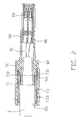
- FIG. 2 is a cross-section view of the cable end connector assembly shown in FIG. 1 along a line of 2-2;
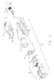
- FIG. 3 is an exploded view of the cable end connector assembly shown in FIG. 1 ;
- FIG. 4 is a perspective view of the cable end connector assembly shown in FIG. 1 with a top cover removed for clearly shown the connecting means;
- FIG. 5 is an exploded view of the cable end connector assembly shown in FIG. 1 from an alternative direction;
- FIG. 6 is an exploded view of a contact module shown in FIG. 3 ;
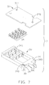
- FIG. 7 is another exploded view of a contact module shown in FIG. 4 from an alternative direction;
- FIG. 8 is an exploded view of a contact module shown in FIG. 4 except that the contacts are soldered onto the printed circuit board;
- FIG. 9 is a perspective view of a connector body shown in FIG. 3 ;
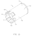
- FIG. 10 is a perspective view of the connecting means of the connector shown in FIG. 3 with the outer ferrule and the inner ferrule in a mated position.
- the cable end connector assembly comprises comprises a connector 100 with a cable 5 terminated to an end thereof.
- the cable 5 is configured by a plurality of conductors 51, a braided shield 53 enclosing the conductors 51, and a jacket 55 enclosing the braided shield 53.
- the cable 5 is arranged with a section of the conductors 51 and braiding 53 exposed at the end.
- the connector 100 comprises a connector body 20 for mating with a complementary mating connector (not shown), a cover means 91, 92 designed for shielding and being used to securely attach the end of the cable 5 to the connector body 20, and connecting means 7 interface between the shield 53 of the cable 5 and the cover means 91, 92.
- the connecting means 7 comprises an outer ferrule 73 and an inner ferrule 73.
- the outer ferrule 73 has a first part 733 crimped onto said jacket 55 for fastening said connecting means 7 to said cable 5 and a second part 731 crimped onto said braided shield 53 for electrical communication.
- the braiding 53 is sandwiched between the inner and outer ferrules 71/ 73. With the interposing of the braiding 53 in between, the inner and outer ferrules 71/ 73 are securely interlocked together.
- the inner ferrule 73 further comprises a plurality of resilient tab 719 and a pair of bumps 717.
- the plurality of resilient tabs 719 flexibly abut against said cover means 91, 92 thereby making electrical connection to said cover means 91, 92. Since the outer ferrule 73 is disposed between the inner ferrule 71 and the cover means 91, 92, a gap is defined there between, which provides a space for the resilient tab 719 slantwise extending towards the cover means 91, 92 therein, which increases the flexibility of the resilient tab 719.
- the bumps 717 mate into a pair of concavities 935, 945 defined in the cover means 91, 92 and thereby securing said connecting means 7 to said cover means 91, 92.
- the cover means 90 (91 /92) is configured by a top cover 92 and a bottom cover 91 each defines a cavity (911/ 921) so as to jointly define a space to receive the connecting means 7 therein.
- Each of the top and bottom covers 91/ 92 further includes a planar portion/ plates 95/95 with the connector body 20 sandwiched therein.
- the connector body 20 further comprises a first contact module 3, a second contact module 4 stacked with said first contact module 3 and an insulating cover 1 insulating said first and second contact modules 3, 4 from said cover means 91, 92.
- Each of the first and the second contact modules 3, 4 comprises a plurality of conductive contacts 35 respectively connected to corresponding conductors 51 of the cable 5, defines a pair of concavities 39 in a first surface, and forms a pair of bumps 38 on a second surface opposite to the first surface.
- the pair of bumps 38 of the second module 4 mates into the pair of concavities 39 of the first contact module 3.
- the first contact module 3 further defines a first side surface 393 in one of the concavities 39, a groove 391 in the first side surface 393, a second side surface 395 opposite to said first side surface 393 in the other concavity 39, and a groove 391 in said second side surface 395.
- Each of said bumps 38 of the second contact module 4 forms a latch 381 corresponding to respective grooves 391 of the first contact module 3.
- the first and the second contact modules 3, 4 have a same configuration.
- the bumps 38 of the second contact module 4 mate into the concavities 39 of the first contact module 3 and the latches 381 of the bumps 38 are snapped into the grooves 391 of the concavities 39 of the first contact module 3 thereby fixing the two contact module 3, 4 together.
- Each of the contact modules 3, 4 comprises a printed circuit board 37 and an insulating housing 33.
- the printed circuit board 37 forms a plurality of first conductive pads 371 connected to the contacts 35, a plurality of second conductive pads 373 and a plurality of conductive trace electrically connected between the first conductive pads 371 and the second conductive pads 373.
- the contacts 35 are respectively soldered onto the first conductive pads 371.
- the conductors 51 are respectively soldered onto the second conductive pads 373.
- the printed circuit board 37 together with the contact 35 is assembled to a side of the insulating housing 33 thereby forming the contact module 3, 4.
- the printed circuit board 37 defines three holes, a pair of holes 377 at a front portion and a hole 378 at a rear portion (referring to FIGs. 6-8 ).
- the housing 33 forms a post 388 and the cover 1 defines a hole 18 aligned with the hole 378 of the printed circuit board 37.
- the housing further forms a pair of posts 341 aligned to the pair of holes 377 of the printed circuit board 37.
- the post 388 of the insulating housing 33 of the second module 4 mates into the hole 378 of the printed circuit board 37 of the first module 3.
- the post 388 of the first contact module 3 mates into the hole 18 of the insulating cover 1.
- the insulating cover 1 comprises a bottom wall 13, a top wall 11 and two side walls 15 connecting opposite ends of said top and bottom walls 11, 13 to define a cavity 17 there between.
- the top wall 11 defines a pair of slot 19 frontwardly extending from a rear end of the top wall 11.
- the bumps 38 of the first contact module 3 extend from the housing 33 and are slidable in the slots 19 when the first and the second contact module 3, 4 are inserted forwardly into said cavity 17.
- the top plate 95 of the top cover 91 defines a pair of apertures 951 receiving the bumps 38 of the first contact module 3 thereby fixing the connector body 20 to the cover means 9.
Landscapes
- Connector Housings Or Holding Contact Members (AREA)
- Details Of Connecting Devices For Male And Female Coupling (AREA)
Abstract
A cable connector assembly includes a cable (5) and a connector (100) terminated to the cable (5). The connector (100) further includes a connector body (20), a cover means (9) fastening the connector body (20) and connecting means (7) securing said cable (5) to the cover means (9). The connecting means (7) further includes an outer ferrule (73) having a first part (733) crimped onto the cable and a second part (731) crimped onto a shield (53) of the cable 5, and an inner ferrule (71) fastened substantially under the shield (53) to the outer ferrule (73) in the area of the second part (731) for making an axial locking between the outer ferrule (73) and the inner ferrule (71). The inner ferrule (71) forms a number of resilient tabs (719) flexibly abutting the cover means (9) thereby making firmly electrical connection to the cover means (9).
Description
- The present invention relates to a cable end connector assembly, and more particularly to a cable end connector assembly having a firm connecting means between a cable and a connector.
-
U.S. Patent No. 6,203,377, issued to Grek et al. on Mar. 20, 2001 , discloses a connector for a cable with at least one conductor and a shielding. The connector comprises a cover means designed for electrical communication, and connecting means connectable to the shielding and the cover means. The connecting means comprises an outer ferrule of which a first part is crimped onto said cable for fastening said connecting means to said cable and a second part is crimped onto said shielding for electrical communication. -
U.S. Patent No. 6,109,976, issued to Zanten et al. on Mar. 14, 2000 , discloses a connector assembly for connecting a shielded cable with a plurality of conductors and a common shielding to a printed circuit board comprises a first connector having a housing of insulating material with contacts connected with the conductors and a metal hood connected with the common shielding. The housing is accommodated in the hood and comprises an insertion part protruding out of the hood along its complete circumference. The connector assembly comprises a second connector with a shielding lying at a distance from the second connector, the second connector having a receiving space for receiving the insertion part of the housing. The second connector with the shielding is mounted on the printed circuit board and the shielding is connected to a corresponding connector of the printed circuit board. The hood is provided with at least one projecting flange connected to the shielding of the second connector when the insertion part of the housing is inserted into the receiving space of the second connector. - An object of the present invention is to provide a cable end connector assembly comprising a cable and an connector firmly terminated to the cable.
- A cable connector assembly comprising a cable, a connector body for mating with a complementary mating connector and connecting means securing said cable to the connector body is provided. The cable comprises a plurality of conductors, a shield and a jacket, and has an end with the plurality of conductors and the shield exposed from the jacket. The cover means is designed for electrical communication and secures said end of the cable to said connector body. The connecting means comprises an outer ferrule having a first part crimped onto said jacket for fastening said connecting means to said cable and a second part crimped onto said shield for electrical communication, and an inner ferrule fastened substantially under said shield to said outer ferrule in the area of the second part for making an axial locking between said outer ferrule and said inner ferrule. The inner ferrule further comprises a plurality of resilient tab flexibly abutting said cover means thereby making electrical connection to the cover means.
- According to another aspect of the present invention, another cable connector assembly is provided. The cable end connector assembly comprises a cable and a connector terminated to the cable. The cable comprises a plurality of conductors and has an end with the plurality of conductors exposed from the jacket. The connector comprises a connector body for mating with a complementary mating connector, a cover means designed for electrical communication and connecting means fixed to the cover means. The end of cable is securely fixed to the connector body by the cover means. The connector body further comprises a first contact module and an insulating cover insulating said first contact module from said cover means. The first contact module comprises a plurality of conductive contacts respectively and electrically connected to corresponding conductors of the cable. The first contact module forms a bump mating with the cover means thereby fixing said connector body to said cover means.
- According to another aspect of the present invention, another cable connector assembly is provided. The cable end connector assembly comprises a cable and a connector terminated to the cable. The cable comprises a plurality of conductors, said cable having an end with the plurality of conductors exposed from the jacket. The connector comprises a connector body for mating with a complementary mating connector, a cover means designed for electrical communication and connecting means fixed to the cover means. The end of the cable is securely fixed to the connector body by the cover means. The connector body further comprises a first contact module, a second contact module stacked with said first contact module and an insulating cover insulating said first and second contact modules from said cover means. Each of the first and the second contact modules comprises a plurality of conductive contacts respectively and electrically connected to corresponding conductors of the cable. The first contact module defines a pair of concavities and the second contact module forms a pair of bumps mating into said concavities of the first contact module thereby fixing the two contact module together.
Viewed from a further aspect, the present invention provides a cable end connector assembly comprising: - a cable comprising a plurality of conductors, said cable having an end exposing the plurality of conductors ; and
- a connector comprising a connector body for mating with a complementary mating connector, a cover means designed for electrical communication and securing said end of the cable to said connector body, and a connecting means fixed to the cover means;
- wherein said connector body further comprises a first contact module and an insulating cover insulating said first contact module from said cover means, said first contact module comprising a plurality of conductive contacts respectively electrically connected to corresponding conductors of the cable, said first contact module forming a bump mating with the cover means, thereby fixing said connector body to said cover means.
- a cable comprising a plurality of conductors having an end with the plurality of conductors exposed;
- a connector comprising a connector body for mating with a complementary mating connector, a cover means designed for electrical communication and securing said end of the cable to said connector body, and a connecting means fixed to the cover means,
- wherein said connector body further comprises a first contact module, a second contact module stacked with said first contact module, and an insulating cover insulating said first and second contact modules from said cover means, each of the first and the second contact modules comprising a plurality of conductive contacts respectively electrically connected to corresponding conductors of the cable, said first contact module defining a pair of concavities, said second contact module forming a pair of bumps mating into said concavities of the first contact module and fixing the two contact module together.
- Other objects, advantages and novel features of the invention will become more apparent from the following detailed description of a preferred embodiment when taken in conjunction with the accompanying drawings.
-
FIG. 1 is a perspective view of a cable end connector assembly according to an embodiment of the present invention; -
FIG. 2 is a cross-section view of the cable end connector assembly shown inFIG. 1 along a line of 2-2; -
FIG. 3 is an exploded view of the cable end connector assembly shown inFIG. 1 ; -
FIG. 4 is a perspective view of the cable end connector assembly shown inFIG. 1 with a top cover removed for clearly shown the connecting means; -
FIG. 5 is an exploded view of the cable end connector assembly shown inFIG. 1 from an alternative direction; -
FIG. 6 is an exploded view of a contact module shown inFIG. 3 ; -
FIG. 7 is another exploded view of a contact module shown inFIG. 4 from an alternative direction; -
FIG. 8 is an exploded view of a contact module shown inFIG. 4 except that the contacts are soldered onto the printed circuit board; -
FIG. 9 is a perspective view of a connector body shown inFIG. 3 ; and -
FIG. 10 is a perspective view of the connecting means of the connector shown inFIG. 3 with the outer ferrule and the inner ferrule in a mated position. - Reference will now be made to the drawing figures to describe the present invention in detail.
- Referring to
FIGs. 1-5 , a cable end connector assembly according to an embodiment of the present invention is shown. The cable end connector assembly comprises comprises aconnector 100 with acable 5 terminated to an end thereof. - The
cable 5 is configured by a plurality ofconductors 51, abraided shield 53 enclosing theconductors 51, and ajacket 55 enclosing thebraided shield 53. Thecable 5 is arranged with a section of theconductors 51 andbraiding 53 exposed at the end. - The
connector 100 comprises aconnector body 20 for mating with a complementary mating connector (not shown), a cover means 91, 92 designed for shielding and being used to securely attach the end of thecable 5 to theconnector body 20, and connecting means 7 interface between theshield 53 of thecable 5 and the cover means 91, 92. - Referring to
FIGs. 2 ,4 and10 , the connecting means 7 comprises anouter ferrule 73 and aninner ferrule 73. Theouter ferrule 73 has afirst part 733 crimped onto saidjacket 55 for fastening said connecting means 7 to saidcable 5 and asecond part 731 crimped onto said braidedshield 53 for electrical communication. Thebraiding 53 is sandwiched between the inner andouter ferrules 71/ 73. With the interposing of thebraiding 53 in between, the inner andouter ferrules 71/ 73 are securely interlocked together. Theinner ferrule 73 further comprises a plurality ofresilient tab 719 and a pair ofbumps 717. The plurality ofresilient tabs 719 flexibly abut against said cover means 91, 92 thereby making electrical connection to said cover means 91, 92. Since theouter ferrule 73 is disposed between theinner ferrule 71 and the cover means 91, 92, a gap is defined there between, which provides a space for theresilient tab 719 slantwise extending towards the cover means 91, 92 therein, which increases the flexibility of theresilient tab 719. Thebumps 717 mate into a pair ofconcavities 935, 945 defined in the cover means 91, 92 and thereby securing said connecting means 7 to said cover means 91, 92. - The cover means 90 (91 /92) is configured by a
top cover 92 and abottom cover 91 each defines a cavity (911/ 921) so as to jointly define a space to receive the connecting means 7 therein. Each of the top and bottom covers 91/ 92 further includes a planar portion/plates 95/95 with theconnector body 20 sandwiched therein. - Referring to
FIGs. 5-9 , theconnector body 20 further comprises afirst contact module 3, a second contact module 4 stacked with saidfirst contact module 3 and an insulatingcover 1 insulating said first andsecond contact modules 3, 4 from said cover means 91, 92. Each of the first and thesecond contact modules 3, 4 comprises a plurality ofconductive contacts 35 respectively connected to correspondingconductors 51 of thecable 5, defines a pair ofconcavities 39 in a first surface, and forms a pair ofbumps 38 on a second surface opposite to the first surface. The pair ofbumps 38 of the second module 4 mates into the pair ofconcavities 39 of thefirst contact module 3. Thefirst contact module 3 further defines afirst side surface 393 in one of theconcavities 39, agroove 391 in thefirst side surface 393, asecond side surface 395 opposite to saidfirst side surface 393 in theother concavity 39, and agroove 391 in saidsecond side surface 395. Each of saidbumps 38 of the second contact module 4 forms alatch 381 corresponding torespective grooves 391 of thefirst contact module 3. In a preferred embodiment of the present invention, the first and thesecond contact modules 3, 4 have a same configuration. When thefirst contact module 3 is stacked with the second contact module 4, thebumps 38 of the second contact module 4 mate into theconcavities 39 of thefirst contact module 3 and thelatches 381 of thebumps 38 are snapped into thegrooves 391 of theconcavities 39 of thefirst contact module 3 thereby fixing the twocontact module 3, 4 together. - Each of the
contact modules 3, 4 comprises a printedcircuit board 37 and an insulatinghousing 33. The printedcircuit board 37 forms a plurality of firstconductive pads 371 connected to thecontacts 35, a plurality of secondconductive pads 373 and a plurality of conductive trace electrically connected between the firstconductive pads 371 and the secondconductive pads 373. Thecontacts 35 are respectively soldered onto the firstconductive pads 371. Theconductors 51 are respectively soldered onto the secondconductive pads 373. The printedcircuit board 37 together with thecontact 35 is assembled to a side of the insulatinghousing 33 thereby forming thecontact module 3, 4. - The printed
circuit board 37 defines three holes, a pair ofholes 377 at a front portion and ahole 378 at a rear portion (referring toFIGs. 6-8 ). Thehousing 33 forms apost 388 and thecover 1 defines ahole 18 aligned with thehole 378 of the printedcircuit board 37. The housing further forms a pair ofposts 341 aligned to the pair ofholes 377 of the printedcircuit board 37. When the printedcircuit board 37 is assembled onto insulatinghousing 33, the pair of theposts 341 of the insulatinghousing 33 mate into the pair of theholes 377 of the printedcircuit board 37 and form the first or thesecond contact modules 3, 4. When the first and thesecond contact modules 3, 4 are stacked together, thepost 388 of the insulatinghousing 33 of the second module 4 mates into thehole 378 of the printedcircuit board 37 of thefirst module 3. When the stacked first andsecond contact modules 3, 4 are inserted into the insulatingcover 1, thepost 388 of thefirst contact module 3 mates into thehole 18 of the insulatingcover 1. - The insulating
cover 1 comprises abottom wall 13, atop wall 11 and twoside walls 15 connecting opposite ends of said top andbottom walls cavity 17 there between. Thetop wall 11 defines a pair ofslot 19 frontwardly extending from a rear end of thetop wall 11. Thebumps 38 of thefirst contact module 3 extend from thehousing 33 and are slidable in theslots 19 when the first and thesecond contact module 3, 4 are inserted forwardly into saidcavity 17. Thetop plate 95 of thetop cover 91 defines a pair ofapertures 951 receiving thebumps 38 of thefirst contact module 3 thereby fixing theconnector body 20 to the cover means 9. - The disclosure is illustrative only, changes may be made in detail, especially in matter of shape, size, and arrangement of parts within the principles of the invention.
The insulating cover may comprise a bottom wall, a top wall and two side walls connecting opposite ends of said top and bottom walls to define a cavity therebetween. The top wall may define two slots beside said two side walls. The first contact module may form another bump mating with the cover means. The two bumps may be slidable in corresponding slots when the first contact module is inserted into the cavity of the insulating cover.
The connector body may further comprise a second contact module stacked with said first contact module. Each of the two contact modules may define a first and an opposite second surfaces. The two bumps disposed on the first surface and each bump may have a latch and two concavities defined in the second surface. The two bumps of the second contact module may be respectively received in the two concavities. The latches may mate with the first contact module.
The connector body may further comprise a second contact module stacked with said first contact module. The first and second contact modules may have a same configuration.
The cover means may comprise a bottom cover and a top cover jointly defining a cavity receiving the connecting means.
The connecting means may comprise an outer ferrule having a first part crimped onto said jacket thereby fastening said connecting means to said cable and a second part crimped onto said shield for electrical communication.
The connecting means may comprise an inner ferrule fastened substantially under said shield to said outer ferrule in the area of the second part for making an axial locking between said outer ferrule and said inner ferrule.
The inner ferrule may further comprise a plurality of resilient tabs flexibly abutting said cover means, thereby making electrical connection to said cover means.
A gap may be defined between the inner ferrule and the cover means. The resilient tab may extend slantwise towards the cover means.
The cover means may comprise a bottom cover and a top cover jointly defining a cavity receiving said connecting means. The top cover and the bottom cover may form a top and a bottom plates. The connector body may be sandwiched between the top plate and the bottom plate.
Viewed from a yet further aspect the present invention provides a cable end connector assembly comprising:
The first contact module may have a pair of bumps extending through said insulating cover and mating with said cover means. The first and the second contact module may have a same configuration.
Each of the first and the second contact modules may further comprise a printed circuit board forming a plurality of first conductive pads connected to said contacts and a plurality of second conductive pads electrically connected between said first conductive pads and said plurality of conductors of the cable.
Each of said first and second contact modules may include an insulative housing receiving the corresponding contacts which are assembled into the housing via an opening in one of the housings along a direction perpendicular to a mating direction of said contacts. The printed circuit board may be assembled to the housing in said direction and may cover said opening so that the printed circuit board defines at least one through hole receiving at least one post unitarily extending from said face of the housing.
The printed circuit board of the first contact module may be sandwiched between the housing of the first contact module and the housing of the second contact module. The printed circuit board of the first contact module may defme a pair of notches on two sides to receive the corresponding bumps of the second contact module.
Claims (11)
- A cable end connector assembly comprising:a cable (5) comprising a plurality of conductors (51), a shield (53) and a jacket (55), said cable (5) having an end exposing said plurality of conductors (51) and said shield (53); anda connector (100) comprising a connector body (20) for mating with a complementary mating connector, a cover means (9) designed for electrical communication and securing said connector body (20), and connecting means (7) fixed to the cover means;wherein said connecting means (7) comprises an outer ferrule (73) having a first part (733) crimped onto said jacket (55) thereby fastening said connecting means (7) to said cable (5) and a second part (731) crimped onto said shield (53) for electrical communication, and an inner ferrule (71) fastened substantially under said shield (53) to said outer ferrule (73) in the area of the second part (731) for making an axial locking between said outer ferrule (73) and said inner ferrule (71);wherein the inner ferrule (71) further comprises a plurality of resilient tab (719) flexibly abutting said cover means (9) thereby making electrical connection to said cover means (9).
- A cable end connector assembly as claimed in claim 1, wherein a gap is defined between the inner ferrule (71) and the cover means (9), said resilient tab (719) extending slantwise towards the cover means (9) therein.
- A cable end connector assembly as claimed in claim 2, wherein the inner ferrule (71) further forms a bump (717) mating into a concavity (935, 945) defined in the cover means (9) and thereby fixing said connecting means (7) to said cover means (9).
- A cable end connector assembly as claimed in claim 3, wherein the cover means (9) comprises a bottom cover (92) having a top surface and defining a half cavity (921) in the top surface, and a top cover (91) having a bottom surface facing the top surface of the bottom cover and defining another half cavity (911) in the bottom surface, the bottom cover (92) and the top cover (91) cooperating to combine the two half cavities (921, 911) into a whole cavity receiving the connecting means (7).
- A cable end connector assembly as claimed in claim 4, wherein the top cover (91) further forms a top plate (95) and the bottom cover (92) forms a bottom plate (96), said connector body (20) sandwiched between the top plate (95) and the bottom plate (96).
- A cable end connector assembly as claimed in claim 1, wherein said connector body (20) further comprises a first contact module (3), a second contact module (3) stacked with said first contact module, and an unitarily formed insulating cover (1) receiving the first and the second contact modules (3) and insulating said first and second contact modules (3) from said cover means (9), each of the first and the second contact modules (3) comprising a plurality of conductive contacts (35) respectively electrically connected to corresponding conductors (51) of the cable (5), said first contact module (3) defining a pair of concavities (39), said second contact module (3) forming a pair of bumps (38) mating into said concavities (39) of the first contact module (3) and fixing the two contact modules (3) together.
- A cable end connector assembly as claimed in claim 6, wherein said first contact module (3) defines a first side surface (393) in one of the concavities (39), a groove (391) in said first side surface (393), a second side surface (395) in the other concavity opposite to said first side surface, and a groove in said second side surface, each of said bumps (38) of the second contact module (3) forming a latch (381) snapped into respective grooves (391) of the first contact module (3), thereby fixing the two contact modules (3) together.
- A cable end connector assembly as claimed in claim 7, wherein the first contact module (1) has a pair of bumps (38) extending through said insulating cover (1) and mating with said cover means (9), and wherein the first and the second contact modules (3) have a same configuration.
- A cable end connector assembly as claimed in claim 8, wherein each of the first and the second contact modules (3) further comprises a printed circuit board (37) forming a plurality of first conductive pads (371) connected to said contacts (35), a plurality of second conductive pads (373) electrically connected between said first conductive pads (371) and said plurality of conductors (51) of the cable (5).
- A cable end connector assembly as claimed in claim 9, wherein each of said first and second contact modules (3) includes an insulative housing (33) receiving the corresponding contacts (35) which are assembled into the housing (33) via an opening in one of the housings along a direction perpendicular to a mating direction of said contacts (35), and wherein the printed circuit board (37) is assembled to the housing (33) in said direction and covers said opening so that the printed circuit board (37) defines at least one through hole (377) receiving at least one post (341) unitarily extending from said face of the housing (37).
- A cable end connector assembly as claimed in claim 10, wherein the printed circuit board (37) of the first contact module (3) is sandwiched between the housing (33) of the first contact module (3) and the housing (33) of the second contact module (3), and wherein the printed circuit board (37) of the first contact module (3) defines a pair of notches on two sides to receive the corresponding bumps (38) of the second contact module (3).
Applications Claiming Priority (4)
| Application Number | Priority Date | Filing Date | Title |
|---|---|---|---|
| CNU2008203026592U CN201303150Y (en) | 2008-11-06 | 2008-11-06 | Cable connector |
| CN2009203019521U CN201430292Y (en) | 2009-04-07 | 2009-04-07 | Cable connector |
| CN2009203019589U CN201430295Y (en) | 2009-04-07 | 2009-04-07 | Cable connector |
| EP09175031A EP2184812A1 (en) | 2008-11-06 | 2009-11-04 | Cable end connector assembly |
Related Parent Applications (1)
| Application Number | Title | Priority Date | Filing Date |
|---|---|---|---|
| EP09175031.5 Division | 2009-11-04 |
Publications (1)
| Publication Number | Publication Date |
|---|---|
| EP2343783A1 true EP2343783A1 (en) | 2011-07-13 |
Family
ID=41571486
Family Applications (2)
| Application Number | Title | Priority Date | Filing Date |
|---|---|---|---|
| EP11162256A Withdrawn EP2343783A1 (en) | 2008-11-06 | 2009-11-04 | Cable end connector assembly |
| EP09175031A Withdrawn EP2184812A1 (en) | 2008-11-06 | 2009-11-04 | Cable end connector assembly |
Family Applications After (1)
| Application Number | Title | Priority Date | Filing Date |
|---|---|---|---|
| EP09175031A Withdrawn EP2184812A1 (en) | 2008-11-06 | 2009-11-04 | Cable end connector assembly |
Country Status (2)
| Country | Link |
|---|---|
| US (1) | US7972172B2 (en) |
| EP (2) | EP2343783A1 (en) |
Cited By (1)
| Publication number | Priority date | Publication date | Assignee | Title |
|---|---|---|---|---|
| WO2024100126A1 (en) * | 2022-11-11 | 2024-05-16 | Belden Deutschland Gmbh | Shielded plug connector with spring sleeve |
Families Citing this family (13)
| Publication number | Priority date | Publication date | Assignee | Title |
|---|---|---|---|---|
| DE102010002176B4 (en) * | 2010-02-22 | 2011-12-15 | Tyco Electronics Amp Gmbh | contactor |
| US8113876B1 (en) * | 2010-07-23 | 2012-02-14 | Tyco Electronics Corporation | Electrical connector for providing electrical power to an antenna |
| US8152566B1 (en) * | 2011-02-16 | 2012-04-10 | Hon Hai Precision Ind. Co., Ltd. | Electrical connector with resilient arm configured in fixed ended beam manner formed on metal shell |
| US8771011B2 (en) | 2011-07-19 | 2014-07-08 | David J Ball | Broadband interface connection system |
| US9124008B2 (en) * | 2013-08-29 | 2015-09-01 | Tyco Electronics Corporation | Electrical connector |
| US9559480B2 (en) * | 2015-01-29 | 2017-01-31 | The Phoenix Company Of Chicago, Inc. | Method and apparatus for making an interconnection between power and signal cables |
| JP6759615B2 (en) * | 2016-02-12 | 2020-09-23 | 株式会社ジェイテクト | Circuit board assembly, insert-molded products, and manufacturing methods for insert-molded products |
| US9647378B1 (en) * | 2016-05-10 | 2017-05-09 | Te Connectivity Corporation | Electrical connector |
| CN110168810B (en) | 2016-12-30 | 2021-05-28 | 安波福中央电气(上海)有限公司 | Shielded cable with boundary contact through assembly |
| US10505317B2 (en) | 2017-05-30 | 2019-12-10 | The Phoenix Company Of Chicago, Inc. | Constant impedance connector system |
| US10049788B1 (en) * | 2017-05-30 | 2018-08-14 | The Phoenix Company Of Chicago, Inc. | Constant impedance connector system for quantum computer applications |
| US10320133B2 (en) | 2017-05-30 | 2019-06-11 | The Phoenix Company Of Chicago, Inc. | Constant impedance connector system |
| WO2022159587A1 (en) * | 2021-01-21 | 2022-07-28 | Commscope Technologies Llc | Connector for a single twisted pair of conductors |
Citations (5)
| Publication number | Priority date | Publication date | Assignee | Title |
|---|---|---|---|---|
| US4307926A (en) * | 1979-04-20 | 1981-12-29 | Amp Inc. | Triaxial connector assembly |
| EP0907221A2 (en) * | 1997-10-01 | 1999-04-07 | Berg Electronics Manufacturing B.V. | Cable interconnection |
| EP0986135A1 (en) * | 1998-09-13 | 2000-03-15 | Framatome Connectors International | Shielded cable connector and method for connecting a shielded cable to it |
| US6109976A (en) | 1998-07-10 | 2000-08-29 | Berg Technology, Inc. | Modular high speed connector |
| US6203377B1 (en) | 1999-01-29 | 2001-03-20 | Fci Katrineholm A.B. | Connector and a method for assembling the connector |
Family Cites Families (13)
| Publication number | Priority date | Publication date | Assignee | Title |
|---|---|---|---|---|
| US4963104A (en) * | 1989-05-01 | 1990-10-16 | Spark Innovations, Inc. | Shielded connector assembly |
| US5060373A (en) * | 1989-08-22 | 1991-10-29 | The Phoenix Company Of Chicago, Inc. | Methods for making coaxial connectors |
| US5180316A (en) * | 1991-03-25 | 1993-01-19 | Molex Incorporated | Shielded electrical connector |
| US5482477A (en) * | 1994-06-28 | 1996-01-09 | The Whitaker Corporation | Micro-miniature coaxial connector with positive locking member |
| US6036543A (en) | 1996-04-04 | 2000-03-14 | Framatome Connectors International | Connector assembly |
| US5913694A (en) * | 1997-11-18 | 1999-06-22 | Osram Sylvania Inc. | Connector assembly |
| US6122239A (en) * | 1998-08-03 | 2000-09-19 | Computer Performance, Inc. | Pre-mastering, archival optical recorder that provides extended recording time |
| US6065998A (en) * | 1998-12-29 | 2000-05-23 | Molex Incorporated | Electrical connector for coaxial cable |
| NL1015059C2 (en) * | 2000-04-28 | 2001-10-30 | Fci S Hertogenbosch B V | Cable connector and kit for assembling it. |
| NL1018175C2 (en) * | 2001-05-30 | 2002-12-03 | Fci Mechelen N V | Plug block and cable connector. |
| CN100429829C (en) * | 2003-11-19 | 2008-10-29 | 西蒙公司 | Cable shield contacts |
| NL1026451C2 (en) * | 2004-06-18 | 2005-12-20 | Framatome Connectors Int | Cable connector and method for assembling a cable and such a cable connector. |
| US7086897B2 (en) * | 2004-11-18 | 2006-08-08 | John Mezzalingua Associates, Inc. | Compression connector and method of use |
-
2009
- 2009-11-04 EP EP11162256A patent/EP2343783A1/en not_active Withdrawn
- 2009-11-04 EP EP09175031A patent/EP2184812A1/en not_active Withdrawn
- 2009-11-05 US US12/612,708 patent/US7972172B2/en not_active Expired - Fee Related
Patent Citations (5)
| Publication number | Priority date | Publication date | Assignee | Title |
|---|---|---|---|---|
| US4307926A (en) * | 1979-04-20 | 1981-12-29 | Amp Inc. | Triaxial connector assembly |
| EP0907221A2 (en) * | 1997-10-01 | 1999-04-07 | Berg Electronics Manufacturing B.V. | Cable interconnection |
| US6109976A (en) | 1998-07-10 | 2000-08-29 | Berg Technology, Inc. | Modular high speed connector |
| EP0986135A1 (en) * | 1998-09-13 | 2000-03-15 | Framatome Connectors International | Shielded cable connector and method for connecting a shielded cable to it |
| US6203377B1 (en) | 1999-01-29 | 2001-03-20 | Fci Katrineholm A.B. | Connector and a method for assembling the connector |
Cited By (2)
| Publication number | Priority date | Publication date | Assignee | Title |
|---|---|---|---|---|
| WO2024100126A1 (en) * | 2022-11-11 | 2024-05-16 | Belden Deutschland Gmbh | Shielded plug connector with spring sleeve |
| JP2025536620A (en) * | 2022-11-11 | 2025-11-07 | ベルデン ドイチュランド ゲゼルシャフト ミット ベシュレンクテル ハフツング | Shielded plug-in connector with spring sleeve |
Also Published As
| Publication number | Publication date |
|---|---|
| US7972172B2 (en) | 2011-07-05 |
| US20100112864A1 (en) | 2010-05-06 |
| EP2184812A1 (en) | 2010-05-12 |
Similar Documents
| Publication | Publication Date | Title |
|---|---|---|
| US7972172B2 (en) | Cable end connector assembly | |
| CN109411957B (en) | High-speed interconnect components | |
| KR960002138B1 (en) | Modular electrical connectors | |
| CN109804511B (en) | connector structure | |
| US6551140B2 (en) | Electrical connector having differential pair terminals with equal length | |
| KR101471283B1 (en) | Electrical connector for use with a circuit board | |
| US20210399502A1 (en) | Mating module and cable connector | |
| TWI528660B (en) | Receptacle assembly | |
| CN109845047B (en) | connector structure | |
| US7497738B2 (en) | Electrical connector interacting between two different interfaces | |
| US6431914B1 (en) | Grounding scheme for a high speed backplane connector system | |
| TWI528661B (en) | Cable header connector | |
| CN110752486B (en) | Connector with a locking member | |
| US8157591B2 (en) | Electrical connector system | |
| US20150255905A1 (en) | Flippable electrical connector | |
| US7134900B2 (en) | Electrical connector assembly with multi-function latching member | |
| US8187034B2 (en) | Electrical connector system | |
| JP6509177B2 (en) | Connector structure | |
| CN102570104A (en) | Electrical connector system | |
| US20020137400A1 (en) | Electrical connector | |
| US7416449B2 (en) | Electrical connector assembly with improved covers | |
| US6036543A (en) | Connector assembly | |
| US20190326710A1 (en) | Interconnection system | |
| CN109256643B (en) | High-speed connector module | |
| TW202230907A (en) | Plug connector |
Legal Events
| Date | Code | Title | Description |
|---|---|---|---|
| PUAI | Public reference made under article 153(3) epc to a published international application that has entered the european phase |
Free format text: ORIGINAL CODE: 0009012 |
|
| AC | Divisional application: reference to earlier application |
Ref document number: 2184812 Country of ref document: EP Kind code of ref document: P |
|
| AK | Designated contracting states |
Kind code of ref document: A1 Designated state(s): AT BE BG CH CY CZ DE DK EE ES FI FR GB GR HR HU IE IS IT LI LT LU LV MC MK MT NL NO PL PT RO SE SI SK SM TR |
|
| STAA | Information on the status of an ep patent application or granted ep patent |
Free format text: STATUS: THE APPLICATION IS DEEMED TO BE WITHDRAWN |
|
| 18D | Application deemed to be withdrawn |
Effective date: 20111114 |