EP2343707A2 - Optical disc reproduction apparatus - Google Patents
Optical disc reproduction apparatus Download PDFInfo
- Publication number
- EP2343707A2 EP2343707A2 EP10197099A EP10197099A EP2343707A2 EP 2343707 A2 EP2343707 A2 EP 2343707A2 EP 10197099 A EP10197099 A EP 10197099A EP 10197099 A EP10197099 A EP 10197099A EP 2343707 A2 EP2343707 A2 EP 2343707A2
- Authority
- EP
- European Patent Office
- Prior art keywords
- main body
- battery pack
- optical disc
- battery
- hinge
- Prior art date
- Legal status (The legal status is an assumption and is not a legal conclusion. Google has not performed a legal analysis and makes no representation as to the accuracy of the status listed.)
- Withdrawn
Links
Images
Classifications
-
- G—PHYSICS
- G11—INFORMATION STORAGE
- G11B—INFORMATION STORAGE BASED ON RELATIVE MOVEMENT BETWEEN RECORD CARRIER AND TRANSDUCER
- G11B33/00—Constructional parts, details or accessories not provided for in the other groups of this subclass
- G11B33/02—Cabinets; Cases; Stands; Disposition of apparatus therein or thereon
- G11B33/022—Cases
- G11B33/025—Portable cases
-
- G—PHYSICS
- G06—COMPUTING OR CALCULATING; COUNTING
- G06F—ELECTRIC DIGITAL DATA PROCESSING
- G06F1/00—Details not covered by groups G06F3/00 - G06F13/00 and G06F21/00
- G06F1/16—Constructional details or arrangements
- G06F1/1613—Constructional details or arrangements for portable computers
- G06F1/1633—Constructional details or arrangements of portable computers not specific to the type of enclosures covered by groups G06F1/1615 - G06F1/1626
- G06F1/1635—Details related to the integration of battery packs and other power supplies such as fuel cells or integrated AC adapter
-
- G—PHYSICS
- G06—COMPUTING OR CALCULATING; COUNTING
- G06F—ELECTRIC DIGITAL DATA PROCESSING
- G06F1/00—Details not covered by groups G06F3/00 - G06F13/00 and G06F21/00
- G06F1/16—Constructional details or arrangements
- G06F1/1613—Constructional details or arrangements for portable computers
- G06F1/1633—Constructional details or arrangements of portable computers not specific to the type of enclosures covered by groups G06F1/1615 - G06F1/1626
- G06F1/1675—Miscellaneous details related to the relative movement between the different enclosures or enclosure parts
- G06F1/1681—Details related solely to hinges
-
- G—PHYSICS
- G11—INFORMATION STORAGE
- G11B—INFORMATION STORAGE BASED ON RELATIVE MOVEMENT BETWEEN RECORD CARRIER AND TRANSDUCER
- G11B33/00—Constructional parts, details or accessories not provided for in the other groups of this subclass
- G11B33/02—Cabinets; Cases; Stands; Disposition of apparatus therein or thereon
- G11B33/027—Covers
-
- G—PHYSICS
- G11—INFORMATION STORAGE
- G11B—INFORMATION STORAGE BASED ON RELATIVE MOVEMENT BETWEEN RECORD CARRIER AND TRANSDUCER
- G11B33/00—Constructional parts, details or accessories not provided for in the other groups of this subclass
- G11B33/12—Disposition of constructional parts in the apparatus, e.g. of power supply, of modules
Definitions
- the present invention relates to an optical disc reproduction apparatus which reproduces an image recorded in an optical disc such as blu-ray disc and DVD (Digital Versatile Disc), for example.
- an optical disc such as blu-ray disc and DVD (Digital Versatile Disc), for example.
- optical disc reproduction apparatus which includes a main body having an optical disc reproduction unit and a liquid crystal display unit for displaying an image reproduced by the optical disc reproduction unit, and the main body and the liquid crystal display unit is rotatably and pivotally connected by a two-axis hinge, that is, the liquid crystal display unit can rotate, open, and close with respect to the main body.
- rotation means horizontal rotation of the liquid crystal display unit
- pivoting means back and forth rotation of the liquid crystal display unit (rotating about a rotation axis extending in a horizontal direction).
- the two-axis hinge has a joint member to the main body in addition to a hinge mechanism, and at least the joint member out of the above members is housed in the main body.
- the portable optical disc reproduction apparatus requires a battery pack.
- Many of the battery packs are mounted on a back end of the main body in the same manner as the two-axis hinge. Accordingly, in the back end of the main body, the two-axis hinge and the battery back should be efficiently housed in the chassis of the main body to make the portable optical disc reproduction apparatus smaller and thinner.
- a prismatic secondary battery is often used as a secondary battery in the battery pack to house the two-axis hinge and the battery pack in the chassis of the main body efficiently.
- FIGS. 1 , 4, and 5 of Japanese Laid-Open Patent Publication No. 11- 134065 and Japanese Laid-Open Patent Publication No. 2005- 165637 there is also a known apparatus in which the battery pack is located avoiding a bottom of the hinge which is located in right and left edges of the back end of the main body, and moreover, as shown in Registered Utility Model No. 3025417 and Japanese Laid-Open Patent Publication No. 8-76898 , there is also a known apparatus in which the battery pack is connected to the back end of the main body.
- the prismatic secondary battery is more expensive than a cylindrical secondary battery, so that a production cost of the whole apparatus rises.
- the battery pack can be located avoiding the bottom of the hinge when the hinge is located in the right and left edges of the back end of the main body as in the case of using one-axis hinge, however, the battery pack cannot be located avoiding the bottom of the hinge when the hinge is located in a center of the back end of the main body as in the case of using the two-axis hinge.
- the battery pack has a recess along a pivoting axis of a hinge mechanism (an axis about which the hinge mechanism turns) so that at least a part of the hinge mechanism along the pivoting axis is stored in the recess of the battery pack (refer to Japan Patent No. 3407990 ).
- this type of apparatus can be reduced in thickness for only a part of a diameter of the pivoting axis of the hinge mechanism at most, so that it is possible to reduce a thickness of a portable information processing apparatus provided with the one-axis hinge in which a part of pivoting axis of the hinge mechanism forms a hinge joint member to the main body, however, it is not possible to reduce a thickness of the apparatus provided with the two-axis hinge in which the hinge joint member to the main body is formed separately from the part of the hinge mechanism.
- the part of pivoting axis of the hinge mechanism is stored in the recess of the battery pack when attaching the battery pack to the main body, so that the battery pack cannot be attached to and detached from the main body in the horizontal direction.
- the present invention is to solve the problem described above, and an object of the present invention is to provide an optical disc reproduction apparatus which can efficiently house a two-axis hinge and a battery pack in a main body to make the apparatus smaller and thinner even though the two-axis hinge is located in a center of a back end of the main body, so that portability of the apparatus can be improved, and moreover, a rise in production cost of the whole apparatus can be prevented.
- an optical disc reproduction apparatus comprising: a main body which has an optical disc reproduction unit to reproduce an image recorded in an optical disc; a display unit which displays the image reproduced by the optical disc reproduction unit; a two-axis hinge which connects the main body and the display unit rotatably and pivotally; and a battery pack which can be attached to and detached from a back end of the main body and supplies electrical power to the main body and the display unit.
- the two-axis hinge has a joint member to connect the two-axis hinge to the main body.
- the main body has not only a hinge mounting-housing portion to attach and house the joint member of the two-axis hinge in a center of the back end, but also a housing recess to house a battery housing of the battery pack on right and left sides of the hinge mounting-housing portion on the back end.
- the battery pack has a U-shaped recess in its center.
- the recess is located in a position corresponding to the hinge mounting-housing portion in the main body, and has a width larger than that of the hinge mounting-housing portion in a rightward-leftward direction.
- the recess in the battery pack is located in a position corresponding to the hinge mounting-housing portion in the main body, and has the width larger than that of the hinge mounting-housing portion in the rightward-leftward direction, and moreover, the housing recess which houses the battery housing of the battery pack on right and left sides of the hinge mounting-housing portion on the back end of the main body.
- the two-axis hinge and the battery pack attached to the center of the back end of the main body can be housed in the main body efficiently, and the apparatus can be made smaller and thinner. As a result, portability of the apparatus can be improved.
- the circuit board for charging and discharging the plural cylindrical secondary batteries in the battery pack can be commonalized, and the rise in the production cost of the whole apparatus can be prevented.
- the housing recesses are provided on the right and left sides of the hinge mounting-housing portion in the back end of the main body to house the battery housings in the battery pack, so that a weight of the whole apparatus can be well-balanced.
- the battery pack has two battery housings in total on its both ends in a longitudinal direction, and the battery housings house plural cylindrical secondary batteries, respectively. According to the above configuration, the apparatus can be made thinner without using an expensive prismatic secondary battery, so that the rise in the production cost of the whole apparatus can be prevented.
- the battery pack has a circuit board for charging and discharging all the cylindrical secondary batteries housed in the two battery housings in common in the recess. According to the above configuration, the rise in the production cost of the whole apparatus can be reliably prevented.
- the housing recess in the main body has a guide bar to attach the battery pack
- a longitudinal direction of the guide bar is a direction parallel to a horizontal surface when putting the main body on the horizontal surface
- the battery pack has a guide groove into which the guide bar can be inserted
- upper surfaces of the battery housings in the battery pack are flat and parallel to a longitudinal direction of the guide groove.
- the longitudinal direction of the guide bar provided on the housing recess in the main body, the longitudinal direction of the guide groove provided in the battery pack, and the upper surfaces of the battery housings in the battery pack are parallel to the horizontal surface, so that in contrast to the invention described in the above Japan Patent No. 3407990 , the battery pack can be easily attached to and detached from the main body in the horizontal direction.
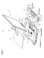
- FIG. 1 is an exploded perspective view of an optical disc reproduction apparatus according to the present preferred embodiment.
- a forward (direction), a backward (direction), a rightward (direction), and a leftward (direction) correspond to forward- backward and rightward- leftward directions indicated by arrows in FIG 1 , respectively.
- An optical disc reproduction apparatus 1 is made up of a main body 2 which has an optical disc reproduction unit 4 to reproduce an image recorded in an optical disc such as a blu-ray disc, a control board 12 to control the whole apparatus, and a liquid crystal display unit 3 (the display unit in claim) to display an image reproduced by the optical disc reproduction unit 4.
- the main body 2 and the liquid crystal display unit 3 is rotatably and pivotally connected to each other by a two-axis hinge 5, that is , the liquid crystal display unit 3 can rotate, open, and close with respect to the main body 2.
- the two-axis hinge 5 connects the main body 2 and the liquid crystal display unit 3, and the main body 2 supports the liquid crystal display unit 3 rotatably and pivotally by using the two-axis hinge 5.
- rotation (rotatably) means horizontal rotation of the liquid crystal display unit 3
- "pivoting (pivotally)” means back and forth (indicated by the arrows in FIG.
- the optical disc reproduction apparatus 1 is portable. When a user takes along the optical disc reproduction apparatus 1, the liquid crystal display unit 3 is folded back on the main body 2 by rotating (pivoting) the two-axis hinge 5 about the rotation axis (pivoting axis) in the horizontal direction to rotate (pivot) the liquid crystal display unit 3 forward.
- the two-axis hinge 5 has a hinge mechanical unit 5a and a joint member 5b for connecting the two-axis hinge 5 to the main body 2.
- the main body 2 has a hinge mounting-housing portion 7 which is a recess to attach and house the joint member 5b of the two-axis hinge 5 in a center of a back end of the main body 2.
- An electrical wiring which connects the main body 2 and the liquid crystal display unit 3 electrically is also housed in the hinge mounting-housing portion 7.
- the electrical wiring goes through the two-axis hinge 5 to connect the main body 2 and the liquid crystal display unit 3 electrically.
- the main body 2 has an inner cover 13 which protects the optical disc reproduction unit 4 and the optical disc attached to the optical disc reproduction unit 4.
- the inner cover 13 is closed to cover and protect the optical disc reproduction unit 4 and the optical disc attached to the optical disc reproduction unit 4.
- the optical disc reproduction apparatus 1 has a battery pack 6 which can be attached to and detached from the back end of the main body 2 and supplies electrical power to the main body 2 and the liquid crystal display unit 3.
- the battery pack 6 has a U-shaped recess 6a in its center.
- the battery pack 6 also has two battery housings in total (a left battery housing 6b and a right battery housing 6c in FIG 1 ) on its both sides (right and left edges) in a longitudinal direction, and the left battery housing 6b and the right battery housing 6c house plural cylindrical secondary batteries 9, respectively.
- the battery pack 6 has a circuit board 10 in the recess 6a to charge and discharge all the cylindrical secondary batteries 9 housed in the left battery housing 6b and the right battery housing 6c in common.
- the recess 6a in the battery pack 6 is located in a position corresponding to the hinge mounting-housing portion 7 in the main body 2 (that is, the location of the recess 6a is right below the hinge mounting-housing portion 7 when attaching the battery pack 6 to the main body 2) and has a width W1 in the rightward-leftward direction larger than a width W2 of the hinge mounting-housing portion 7 in the rightward-leftward direction.
- the main body 2 has a left housing recess 8a and a right housing recess 8b in right and left sides of the hinge mounting-housing portion 7 on the back end to house the left battery housing 6b and the right battery housing 6c in the battery pack 6.
- the two-axis hinge 5 and the battery pack 6 attached to the center of the back end of the main body 2 can be efficiently housed in the back of the main body 2, and the whole optical disc reproduction apparatus 1 can be made smaller and thinner.
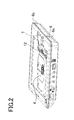
- FIG. 2 shows the main body 2 to which the battery pack 6 is attached. As shown in FIG. 2 , the above structural feature enables the battery pack 6 to be efficiently housed in the back of the main body 2.
- a guide bar 11 and a guide groove 21 is provided on internal surfaces of the left housing recess 8a and the right housing recess 8b in the main body 2 to attach the battery pack 6.
- a longitudinal direction of the guide bar 11 and the guide groove 21 is a direction (the forward-backward direction indicated by the arrows in FIG 1 ) parallel to a horizontal surface when putting the main body 2 on the horizontal surface.
- the battery pack 6 has a guide groove 6e into which the guide bar 11 can be inserted on its right lateral side and left lateral side.
- a guide rail 31 is provided on a right lateral side of the left battery housing 6b and a left lateral side of the right battery housing 6c in the battery pack 6 so that it can be inserted into the guide groove 21 of the main body 2. Furthermore, upper surfaces 6f and 6g of the left and right battery housings 6b and 6c in the battery pack 6 are both flat and parallel to a longitudinal direction of the guide groove 6e and the guide rail 31.
- the longitudinal direction of the guide bar 11 and the guide groove 21 provided on the internal surfaces of the left housing recess 8a and the right housing recess 8b in the main body 2, the longitudinal direction of the guide groove 6e and the guide rail 31 provided in the battery pack 6, and the upper surfaces 6f and 6g of the left and right battery housings 6b and 6c in the battery pack 6 are parallel to the horizontal surface, so that in contrast to the invention described in the above Japan Patent No. 3407990 , the battery pack 6 can be easily attached to and detached from the main body 2 in the horizontal direction.
- the recess 6a in the battery pack 6 is located in a position corresponding to the hinge mounting-housing portion 7 in the main body 2, and the recess 6a has the width W1 in the rightward-leftward direction larger than the width W2 of the hinge mounting-housing portion 7 in the rightward-leftward direction, and moreover, the left housing recess 8a and the right housing recess 8b are provided on the right and left sides of the hinge mounting-housing portion 7 in the back end of the main body 2 to house the left battery housing 6b and the right battery housing 6c in the battery pack 6.
- the two-axis hinge 5 and the battery pack 6 attached to the center of the back end of the main body 2 can be efficiently housed in the main body 2, so that the apparatus can be made smaller and thinner, and portability of the apparatus can be improved. As a result, portability of the optical disc reproduction apparatus 1 can be improved.
- the battery packs are separately provided on the both sides of the main body so that the hinge is located between the battery packs as described in claim 2 of Japanese Laid-Open Patent Publication No.
- all the cylindrical secondary batteries 9 in the battery pack 6 can be electrically connected to each other, so that the circuit board 10 for charging and discharging all the cylindrical secondary batteries 9 can be commonalized, and the rise in production cost of the whole apparatus can be prevented.
- the left housing recess 8a and the right housing recess 8b are provided on the right and left sides of the hinge mounting-housing portion 7 in the back end of the main body 2 to house the left battery housing 6b and the right battery housing 6c in the battery pack 6, so that a weight of the whole apparatus can be well-balanced.
- the apparatus can be made thinner without using the expensive prismatic secondary battery, so that the rise in production cost of the whole apparatus can be prevented.
- the present invention is not limited to the configuration of the above preferred embodiment, however, various modification are applicable within the scope of the invention.
- the display unit is not limited to the liquid crystal display unit, but a plasma display unit or an organic EL (electroluminescence) display unit can also be applied, for example.
- the battery pack has the common circuit board for charging and discharging all the cylindrical secondary batteries in the recess, however, the common circuit board for charging and discharging all the batteries can also be provided in the internal surface or the bottom surface of the left battery housing or the right battery housing.
- each of the guide bars 11 which are provided on the internal surfaces of the left housing recess 8a and the right housing recess 8b in the main body 2 forms one line, however, not only one line but also plural lines in vertical direction or the forward-backward direction are also applicable as long as the longitudinal direction of the guide bar is parallel to the longitudinal direction of the guide groove in the battery pack and the upper surface of the right and left battery housings in the battery pack.
- the example of attaching/detaching the battery pack 6 to/from the main body 2 in the horizontal direction is described, however, the battery pack can also be attached to the main body by moving the battery pack in the forward direction in FIG.
- each of the guide bars on the main body has an inverted L shape and each guide grooves in the battery pack has a L shape.
- the guide bar on the main body is inserted into the guide groove in the battery pack, the battery pack can be moved along the guide bar. According to the above configuration, the battery pack can smoothly be attached to the main body.
Landscapes
- Engineering & Computer Science (AREA)
- Computer Hardware Design (AREA)
- Theoretical Computer Science (AREA)
- Human Computer Interaction (AREA)
- Physics & Mathematics (AREA)
- General Engineering & Computer Science (AREA)
- General Physics & Mathematics (AREA)
- Power Engineering (AREA)
- Battery Mounting, Suspending (AREA)
Abstract
Description
- The present invention relates to an optical disc reproduction apparatus which reproduces an image recorded in an optical disc such as blu-ray disc and DVD (Digital Versatile Disc), for example.
- Recently, in a field of a portable optical disc reproduction apparatus, there is a known optical disc reproduction apparatus which includes a main body having an optical disc reproduction unit and a liquid crystal display unit for displaying an image reproduced by the optical disc reproduction unit, and the main body and the liquid crystal display unit is rotatably and pivotally connected by a two-axis hinge, that is, the liquid crystal display unit can rotate, open, and close with respect to the main body. Here, "rotation (rotatably)" means horizontal rotation of the liquid crystal display unit, and "pivoting (pivotally)" means back and forth rotation of the liquid crystal display unit (rotating about a rotation axis extending in a horizontal direction). The two-axis hinge has a joint member to the main body in addition to a hinge mechanism, and at least the joint member out of the above members is housed in the main body. Thus, it is necessary to have a space for housing not only the optical disc reproduction unit and a control board but also the joint member of the two-axis hinge in a chassis of the main body in the portable optical disc reproduction apparatus.
- Moreover, the portable optical disc reproduction apparatus requires a battery pack. Many of the battery packs are mounted on a back end of the main body in the same manner as the two-axis hinge. Accordingly, in the back end of the main body, the two-axis hinge and the battery back should be efficiently housed in the chassis of the main body to make the portable optical disc reproduction apparatus smaller and thinner.
- In some of the above type of apparatuses, a prismatic secondary battery is often used as a secondary battery in the battery pack to house the two-axis hinge and the battery pack in the chassis of the main body efficiently. As shown in
FIGS. 1 , 4, and 5 of Japanese Laid-Open Patent Publication No.11- 134065 2005- 165637 3025417 8-76898 - Although the above apparatus which uses the prismatic secondary battery as the secondary battery in the battery pack can be thin, the prismatic secondary battery is more expensive than a cylindrical secondary battery, so that a production cost of the whole apparatus rises. Moreover, in the inventions described in
FIGS. 1 , 4, and 5 of Publication No. 11-134065 and Publication No.2005- 165637 claim 2 of Publication No.11- 134065 3025417 8-76898 - In a field of the above type of the apparatus, there is a known apparatus in which the battery pack has a recess along a pivoting axis of a hinge mechanism (an axis about which the hinge mechanism turns) so that at least a part of the hinge mechanism along the pivoting axis is stored in the recess of the battery pack (refer to Japan Patent No.
3407990 - The present invention is to solve the problem described above, and an object of the present invention is to provide an optical disc reproduction apparatus which can efficiently house a two-axis hinge and a battery pack in a main body to make the apparatus smaller and thinner even though the two-axis hinge is located in a center of a back end of the main body, so that portability of the apparatus can be improved, and moreover, a rise in production cost of the whole apparatus can be prevented.
- According to the present invention, this object is achieved by an optical disc reproduction apparatus, comprising: a main body which has an optical disc reproduction unit to reproduce an image recorded in an optical disc; a display unit which displays the image reproduced by the optical disc reproduction unit; a two-axis hinge which connects the main body and the display unit rotatably and pivotally; and a battery pack which can be attached to and detached from a back end of the main body and supplies electrical power to the main body and the display unit.
- The two-axis hinge has a joint member to connect the two-axis hinge to the main body.
- The main body has not only a hinge mounting-housing portion to attach and house the joint member of the two-axis hinge in a center of the back end, but also a housing recess to house a battery housing of the battery pack on right and left sides of the hinge mounting-housing portion on the back end.
- The battery pack has a U-shaped recess in its center.
- The recess is located in a position corresponding to the hinge mounting-housing portion in the main body, and has a width larger than that of the hinge mounting-housing portion in a rightward-leftward direction.
- According to the above configuration, the recess in the battery pack is located in a position corresponding to the hinge mounting-housing portion in the main body, and has the width larger than that of the hinge mounting-housing portion in the rightward-leftward direction, and moreover, the housing recess which houses the battery housing of the battery pack on right and left sides of the hinge mounting-housing portion on the back end of the main body. Thus, the two-axis hinge and the battery pack attached to the center of the back end of the main body can be housed in the main body efficiently, and the apparatus can be made smaller and thinner. As a result, portability of the apparatus can be improved. Moreover, in contrast to the case that the battery packs are separately provided on the both sides of the main body so that the hinge is located between the battery packs as described in
claim 2 of Japanese Laid-Open Patent Publication No.11- 134065 - It is preferable that the battery pack has two battery housings in total on its both ends in a longitudinal direction, and the battery housings house plural cylindrical secondary batteries, respectively. According to the above configuration, the apparatus can be made thinner without using an expensive prismatic secondary battery, so that the rise in the production cost of the whole apparatus can be prevented.
- It is more preferable that the battery pack has a circuit board for charging and discharging all the cylindrical secondary batteries housed in the two battery housings in common in the recess. According to the above configuration, the rise in the production cost of the whole apparatus can be reliably prevented.
- It is preferable that the housing recess in the main body has a guide bar to attach the battery pack, a longitudinal direction of the guide bar is a direction parallel to a horizontal surface when putting the main body on the horizontal surface, the battery pack has a guide groove into which the guide bar can be inserted, and upper surfaces of the battery housings in the battery pack are flat and parallel to a longitudinal direction of the guide groove. According to the above configuration, when the battery pack is attached to and detached from the main body while putting the main body on the horizontal surface, the longitudinal direction of the guide bar provided on the housing recess in the main body, the longitudinal direction of the guide groove provided in the battery pack, and the upper surfaces of the battery housings in the battery pack are parallel to the horizontal surface, so that in contrast to the invention described in the above Japan Patent No.
3407990 - The present invention will be described below with reference to the annexed drawings. It is to be noted that all the drawings are shown for the purpose of illustrating the technical concept of the present invention or embodiments thereof, wherein:
-
FIG 1 is an exploded perspective view of an optical disc reproduction apparatus according to a preferred embodiment of the present invention; and -
FIG 2 is a perspective view of a main body inFIG. 1 to which a battery pack is attached. - A preferred embodiment of the present invention is described with reference to
FIGS. 1 and2 .FIG. 1 is an exploded perspective view of an optical disc reproduction apparatus according to the present preferred embodiment. In the following description and claims, a forward (direction), a backward (direction), a rightward (direction), and a leftward (direction) correspond to forward- backward and rightward- leftward directions indicated by arrows inFIG 1 , respectively. An optical disc reproduction apparatus 1 is made up of amain body 2 which has an opticaldisc reproduction unit 4 to reproduce an image recorded in an optical disc such as a blu-ray disc, acontrol board 12 to control the whole apparatus, and a liquid crystal display unit 3 (the display unit in claim) to display an image reproduced by the opticaldisc reproduction unit 4. Themain body 2 and the liquidcrystal display unit 3 is rotatably and pivotally connected to each other by a two-axis hinge 5, that is , the liquidcrystal display unit 3 can rotate, open, and close with respect to themain body 2. In other words, the two-axis hinge 5 connects themain body 2 and the liquidcrystal display unit 3, and themain body 2 supports the liquidcrystal display unit 3 rotatably and pivotally by using the two-axis hinge 5. Here, "rotation (rotatably)" means horizontal rotation of the liquidcrystal display unit 3, and "pivoting (pivotally)" means back and forth (indicated by the arrows inFIG. 1 ) rotation of the liquid crystal display unit 3 (rotating about a rotation axis of the two-axis hinge 2 extending in the horizontal direction). The optical disc reproduction apparatus 1 is portable. When a user takes along the optical disc reproduction apparatus 1, the liquidcrystal display unit 3 is folded back on themain body 2 by rotating (pivoting) the two-axis hinge 5 about the rotation axis (pivoting axis) in the horizontal direction to rotate (pivot) the liquidcrystal display unit 3 forward. - The two-
axis hinge 5 has a hingemechanical unit 5a and ajoint member 5b for connecting the two-axis hinge 5 to themain body 2. Themain body 2 has a hinge mounting-housing portion 7 which is a recess to attach and house thejoint member 5b of the two-axis hinge 5 in a center of a back end of themain body 2. An electrical wiring which connects themain body 2 and the liquidcrystal display unit 3 electrically is also housed in the hinge mounting-housing portion 7. The electrical wiring goes through the two-axis hinge 5 to connect themain body 2 and the liquidcrystal display unit 3 electrically. After the two-axis hinge 5 is attached to themain body 2 and the electrical wiring connection to themain body 2 is completed, an upper portion of the hinge mounting-housing portion 7 is covered with acover 14. - The
main body 2 has aninner cover 13 which protects the opticaldisc reproduction unit 4 and the optical disc attached to the opticaldisc reproduction unit 4. When taking along the optical disc reproduction apparatus 1 or reproducing the image by the opticaldisc reproduction unit 4, theinner cover 13 is closed to cover and protect the opticaldisc reproduction unit 4 and the optical disc attached to the opticaldisc reproduction unit 4. - The optical disc reproduction apparatus 1 has a
battery pack 6 which can be attached to and detached from the back end of themain body 2 and supplies electrical power to themain body 2 and the liquidcrystal display unit 3. Thebattery pack 6 has a U-shapedrecess 6a in its center. Thebattery pack 6 also has two battery housings in total (aleft battery housing 6b and aright battery housing 6c inFIG 1 ) on its both sides (right and left edges) in a longitudinal direction, and theleft battery housing 6b and theright battery housing 6c house plural cylindricalsecondary batteries 9, respectively. Moreover, thebattery pack 6 has acircuit board 10 in therecess 6a to charge and discharge all the cylindricalsecondary batteries 9 housed in theleft battery housing 6b and theright battery housing 6c in common. - Next, a structural feature of the
battery pack 6 and themain body 2 for housing efficiently thebattery pack 6 in themain body 2 is described. Therecess 6a in thebattery pack 6 is located in a position corresponding to the hinge mounting-housing portion 7 in the main body 2 (that is, the location of therecess 6a is right below the hinge mounting-housing portion 7 when attaching thebattery pack 6 to the main body 2) and has a width W1 in the rightward-leftward direction larger than a width W2 of the hinge mounting-housing portion 7 in the rightward-leftward direction. Themain body 2 has aleft housing recess 8a and aright housing recess 8b in right and left sides of the hinge mounting-housing portion 7 on the back end to house theleft battery housing 6b and theright battery housing 6c in thebattery pack 6. According to the above configuration, the two-axis hinge 5 and thebattery pack 6 attached to the center of the back end of themain body 2 can be efficiently housed in the back of themain body 2, and the whole optical disc reproduction apparatus 1 can be made smaller and thinner. -
FIG. 2 shows themain body 2 to which thebattery pack 6 is attached. As shown inFIG. 2 , the above structural feature enables thebattery pack 6 to be efficiently housed in the back of themain body 2. - Next, a structural feature of the
battery pack 6 and themain body 2 for easily attaching/detaching theabove battery pack 6 to/from themain body 2 in the horizontal direction is described. As shown inFIG 1 , aguide bar 11 and aguide groove 21 is provided on internal surfaces of theleft housing recess 8a and theright housing recess 8b in themain body 2 to attach thebattery pack 6. A longitudinal direction of theguide bar 11 and theguide groove 21 is a direction (the forward-backward direction indicated by the arrows inFIG 1 ) parallel to a horizontal surface when putting themain body 2 on the horizontal surface. On the other hand, thebattery pack 6 has aguide groove 6e into which theguide bar 11 can be inserted on its right lateral side and left lateral side. Moreover, aguide rail 31 is provided on a right lateral side of theleft battery housing 6b and a left lateral side of theright battery housing 6c in thebattery pack 6 so that it can be inserted into theguide groove 21 of themain body 2. Furthermore,upper surfaces right battery housings battery pack 6 are both flat and parallel to a longitudinal direction of theguide groove 6e and theguide rail 31. - According to the above configuration, when the
battery pack 6 is attached to and detached from themain body 2 while putting themain body 2 on the horizontal surface, the longitudinal direction of theguide bar 11 and theguide groove 21 provided on the internal surfaces of theleft housing recess 8a and theright housing recess 8b in themain body 2, the longitudinal direction of theguide groove 6e and theguide rail 31 provided in thebattery pack 6, and theupper surfaces right battery housings battery pack 6 are parallel to the horizontal surface, so that in contrast to the invention described in the above Japan Patent No.3407990 battery pack 6 can be easily attached to and detached from themain body 2 in the horizontal direction. - As described above, according to the optical disc reproduction apparatus 1 of the present preferred embodiment, the
recess 6a in thebattery pack 6 is located in a position corresponding to the hinge mounting-housing portion 7 in themain body 2, and therecess 6a has the width W1 in the rightward-leftward direction larger than the width W2 of the hinge mounting-housing portion 7 in the rightward-leftward direction, and moreover, theleft housing recess 8a and theright housing recess 8b are provided on the right and left sides of the hinge mounting-housing portion 7 in the back end of themain body 2 to house theleft battery housing 6b and theright battery housing 6c in thebattery pack 6. According to the above configuration, the two-axis hinge 5 and thebattery pack 6 attached to the center of the back end of themain body 2 can be efficiently housed in themain body 2, so that the apparatus can be made smaller and thinner, and portability of the apparatus can be improved. As a result, portability of the optical disc reproduction apparatus 1 can be improved. Moreover, in contrast to the case that the battery packs are separately provided on the both sides of the main body so that the hinge is located between the battery packs as described inclaim 2 of Japanese Laid-Open Patent Publication No.11- 134065 secondary batteries 9 in thebattery pack 6 can be electrically connected to each other, so that thecircuit board 10 for charging and discharging all the cylindricalsecondary batteries 9 can be commonalized, and the rise in production cost of the whole apparatus can be prevented. Furthermore, theleft housing recess 8a and theright housing recess 8b are provided on the right and left sides of the hinge mounting-housing portion 7 in the back end of themain body 2 to house theleft battery housing 6b and theright battery housing 6c in thebattery pack 6, so that a weight of the whole apparatus can be well-balanced. - Moreover, the apparatus can be made thinner without using the expensive prismatic secondary battery, so that the rise in production cost of the whole apparatus can be prevented.
- The present invention is not limited to the configuration of the above preferred embodiment, however, various modification are applicable within the scope of the invention. For example, in the above preferred embodiment, the example of applying the liquid crystal display unit to the display unit in claims is described, however, the display unit is not limited to the liquid crystal display unit, but a plasma display unit or an organic EL (electroluminescence) display unit can also be applied, for example. Moreover, in the above preferred embodiment, the battery pack has the common circuit board for charging and discharging all the cylindrical secondary batteries in the recess, however, the common circuit board for charging and discharging all the batteries can also be provided in the internal surface or the bottom surface of the left battery housing or the right battery housing. Moreover, in the above preferred embodiment, there is the example that each of the guide bars 11 which are provided on the internal surfaces of the
left housing recess 8a and theright housing recess 8b in themain body 2 forms one line, however, not only one line but also plural lines in vertical direction or the forward-backward direction are also applicable as long as the longitudinal direction of the guide bar is parallel to the longitudinal direction of the guide groove in the battery pack and the upper surface of the right and left battery housings in the battery pack. Furthermore, in the above preferred embodiment, the example of attaching/detaching thebattery pack 6 to/from themain body 2 in the horizontal direction is described, however, the battery pack can also be attached to the main body by moving the battery pack in the forward direction inFIG. 1 horizontally after lifting up the battery pack from an underside of the main body. In this case, it is preferable that each of the guide bars on the main body has an inverted L shape and each guide grooves in the battery pack has a L shape. Thus, the guide bar on the main body is inserted into the guide groove in the battery pack, the battery pack can be moved along the guide bar. According to the above configuration, the battery pack can smoothly be attached to the main body.
Claims (6)
- An optical disc reproduction apparatus, comprising:a main body which has an optical disc reproduction unit to reproduce an image recorded in an optical disc;a display unit which displays the image reproduced by the optical disc reproduction unit;a two-axis hinge which connects the main body and the display unit rotatably and pivotally; anda battery pack which can be attached to and detached from a back end of the main body and supplies electrical power to the main body and the display unit,wherein the two-axis hinge has a joint member to connect the two-axis hinge to the main body,wherein the main body has not only a hinge mounting-housing portion to attach and house the joint member of the two-axis hinge in a center of the back end, but also a housing recess to house a battery housing of the battery pack on right and left sides of the hinge mounting-housing portion on the back end,wherein the battery pack has a U-shaped recess in its center, andwherein the recess is located in a position corresponding to the hinge mounting-housing portion in the main body, and has a width larger than that of the hinge mounting-housing portion in a rightward-leftward direction.
- The optical disc reproduction apparatus according to claim 1, wherein the battery pack has two battery housings in total on its both ends in a longitudinal direction, and the battery housings house plural cylindrical secondary batteries, respectively.
- The optical disc reproduction apparatus according to claim 2, wherein the battery pack has a circuit board for charging and discharging all the cylindrical secondary batteries housed in the two battery housings in common in the recess.
- The optical disc reproduction apparatus according to claim 3, wherein the housing recess in the main body has a guide bar to attach the battery pack,
wherein a longitudinal direction of the guide bar is a direction parallel to a horizontal surface when putting the main body on the horizontal surface,
wherein the battery pack has a guide groove into which the guide bar can be inserted, and
wherein upper surfaces of the battery housings in the battery pack are flat and parallel to a longitudinal direction of the guide groove. - The optical disc reproduction apparatus according to claim 2, wherein the housing recess in the main body has a guide bar to attach the battery pack,
wherein a longitudinal direction of the guide bar is a direction parallel to a horizontal surface when putting the main body on the horizontal surface,
wherein the battery pack has a guide groove into which the guide bar can be inserted, and
wherein upper surfaces of the battery housings in the battery pack are flat and parallel to a longitudinal direction of the guide groove. - The optical disc reproduction apparatus according to claim 1, wherein the housing recess in the main body has a guide bar to attach the battery pack,
wherein a longitudinal direction of the guide bar is a direction parallel to a horizontal surface when putting the main body on the horizontal surface,
wherein the battery pack has a guide groove into which the guide bar can be inserted, and
wherein upper surfaces of the battery housings in the battery pack are flat and parallel to a longitudinal direction of the guide groove.
Applications Claiming Priority (1)
| Application Number | Priority Date | Filing Date | Title |
|---|---|---|---|
| JP2010001590A JP2011141921A (en) | 2010-01-06 | 2010-01-06 | Optical disc playback apparatus |
Publications (2)
| Publication Number | Publication Date |
|---|---|
| EP2343707A2 true EP2343707A2 (en) | 2011-07-13 |
| EP2343707A3 EP2343707A3 (en) | 2012-11-21 |
Family
ID=43815754
Family Applications (1)
| Application Number | Title | Priority Date | Filing Date |
|---|---|---|---|
| EP10197099A Withdrawn EP2343707A3 (en) | 2010-01-06 | 2010-12-28 | Optical disc reproduction apparatus |
Country Status (3)
| Country | Link |
|---|---|
| US (1) | US8456813B2 (en) |
| EP (1) | EP2343707A3 (en) |
| JP (1) | JP2011141921A (en) |
Cited By (1)
| Publication number | Priority date | Publication date | Assignee | Title |
|---|---|---|---|---|
| EP2343622A2 (en) * | 2010-01-06 | 2011-07-13 | Funai Electric Co., Ltd. | Electronic apparatus for displaying images |
Families Citing this family (1)
| Publication number | Priority date | Publication date | Assignee | Title |
|---|---|---|---|---|
| DE102005022367B4 (en) * | 2005-05-10 | 2021-05-20 | Sew-Eurodrive Gmbh & Co Kg | Contactlessly supplied consumer and system |
Citations (6)
| Publication number | Priority date | Publication date | Assignee | Title |
|---|---|---|---|---|
| GB2011156A (en) * | 1977-12-22 | 1979-07-04 | Philips Nv | Battery holder |
| JPH0325417B2 (en) | 1981-02-12 | 1991-04-05 | Degussa | |
| JPH0876898A (en) | 1994-09-06 | 1996-03-22 | Citizen Watch Co Ltd | Portable computer with detachable battery pack |
| JPH11134065A (en) | 1997-10-30 | 1999-05-21 | Toshiba Corp | Portable electronic devices |
| JP3407990B2 (en) | 1994-09-06 | 2003-05-19 | シチズン時計株式会社 | Information processing device |
| JP2005165637A (en) | 2003-11-11 | 2005-06-23 | Sony Corp | Electronic equipment and battery |
Family Cites Families (6)
| Publication number | Priority date | Publication date | Assignee | Title |
|---|---|---|---|---|
| US5583744A (en) * | 1994-09-06 | 1996-12-10 | Citizen Watch Co., Ltd. | Portable computer with detachable battery pack |
| US5594617A (en) | 1994-12-06 | 1997-01-14 | Digital Equipment Corporation | Rotating battery hinge for a notebook computer |
| KR100598083B1 (en) | 1999-01-22 | 2006-07-07 | 삼성전자주식회사 | Structure for mounting a battery pack on an electronic device |
| KR100924038B1 (en) | 2002-08-29 | 2009-11-02 | 엘지전자 주식회사 | Keyboard removal device for portable hybrid computer |
| JP2005157789A (en) * | 2003-11-26 | 2005-06-16 | Toshiba Corp | Electronics |
| JP2007058579A (en) * | 2005-08-24 | 2007-03-08 | Fujitsu Ltd | Electronics |
-
2010
- 2010-01-06 JP JP2010001590A patent/JP2011141921A/en not_active Withdrawn
- 2010-12-28 US US12/979,749 patent/US8456813B2/en not_active Expired - Fee Related
- 2010-12-28 EP EP10197099A patent/EP2343707A3/en not_active Withdrawn
Patent Citations (6)
| Publication number | Priority date | Publication date | Assignee | Title |
|---|---|---|---|---|
| GB2011156A (en) * | 1977-12-22 | 1979-07-04 | Philips Nv | Battery holder |
| JPH0325417B2 (en) | 1981-02-12 | 1991-04-05 | Degussa | |
| JPH0876898A (en) | 1994-09-06 | 1996-03-22 | Citizen Watch Co Ltd | Portable computer with detachable battery pack |
| JP3407990B2 (en) | 1994-09-06 | 2003-05-19 | シチズン時計株式会社 | Information processing device |
| JPH11134065A (en) | 1997-10-30 | 1999-05-21 | Toshiba Corp | Portable electronic devices |
| JP2005165637A (en) | 2003-11-11 | 2005-06-23 | Sony Corp | Electronic equipment and battery |
Cited By (1)
| Publication number | Priority date | Publication date | Assignee | Title |
|---|---|---|---|---|
| EP2343622A2 (en) * | 2010-01-06 | 2011-07-13 | Funai Electric Co., Ltd. | Electronic apparatus for displaying images |
Also Published As
| Publication number | Publication date |
|---|---|
| JP2011141921A (en) | 2011-07-21 |
| EP2343707A3 (en) | 2012-11-21 |
| US8456813B2 (en) | 2013-06-04 |
| US20110164360A1 (en) | 2011-07-07 |
Similar Documents
| Publication | Publication Date | Title |
|---|---|---|
| US7989101B2 (en) | Battery device, electronic apparatus, and battery system | |
| US8183825B2 (en) | Docking charger for charging a hand held electronic device with or without a protective cover case fitted thereon | |
| CN101136464B (en) | Battery device, electronic apparatus, and battery system | |
| US20050255895A1 (en) | Adaptable charging cradle with speaker for portable communication devices | |
| JP2012173878A (en) | Electronic apparatus | |
| US8025994B2 (en) | Electronic appliance | |
| US8996149B2 (en) | Portable radio sets | |
| US8456813B2 (en) | Optical disc reproduction apparatus | |
| JP2011249018A (en) | Battery charger for battery pack | |
| JP2011071002A (en) | Information processing device | |
| JP2021122135A (en) | Holding device | |
| JP2011182566A (en) | Charging power supply device | |
| JP5677402B2 (en) | Electronics | |
| JP3176960U (en) | Multifunctional storage case for smartphone | |
| JP3128228U (en) | Charger | |
| JP4350699B2 (en) | Mobile phone charger and electronic device charger | |
| JPH10222258A (en) | Portable computer with removable battery pack | |
| US11196121B2 (en) | Battery device, electronic apparatus, and battery system | |
| US20110164369A1 (en) | Electronic apparatus | |
| US20110209163A1 (en) | Electronic apparatus | |
| JP5147193B2 (en) | Battery pack | |
| US8413177B2 (en) | Information-processing equipment | |
| JP2009230712A (en) | Media reproduction device | |
| KR102602283B1 (en) | Wireless charger | |
| CN212966919U (en) | Desktop display device |
Legal Events
| Date | Code | Title | Description |
|---|---|---|---|
| PUAI | Public reference made under article 153(3) epc to a published international application that has entered the european phase |
Free format text: ORIGINAL CODE: 0009012 |
|
| AK | Designated contracting states |
Kind code of ref document: A2 Designated state(s): AL AT BE BG CH CY CZ DE DK EE ES FI FR GB GR HR HU IE IS IT LI LT LU LV MC MK MT NL NO PL PT RO RS SE SI SK SM TR |
|
| AX | Request for extension of the european patent |
Extension state: BA ME |
|
| PUAL | Search report despatched |
Free format text: ORIGINAL CODE: 0009013 |
|
| AK | Designated contracting states |
Kind code of ref document: A3 Designated state(s): AL AT BE BG CH CY CZ DE DK EE ES FI FR GB GR HR HU IE IS IT LI LT LU LV MC MK MT NL NO PL PT RO RS SE SI SK SM TR |
|
| AX | Request for extension of the european patent |
Extension state: BA ME |
|
| RIC1 | Information provided on ipc code assigned before grant |
Ipc: G11B 33/12 20060101ALI20121017BHEP Ipc: G06F 1/16 20060101ALI20121017BHEP Ipc: G11B 33/02 20060101AFI20121017BHEP |
|
| 17P | Request for examination filed |
Effective date: 20130424 |
|
| 17Q | First examination report despatched |
Effective date: 20130605 |
|
| STAA | Information on the status of an ep patent application or granted ep patent |
Free format text: STATUS: THE APPLICATION IS DEEMED TO BE WITHDRAWN |
|
| 18D | Application deemed to be withdrawn |
Effective date: 20131016 |