EP2343622A2 - Electronic apparatus for displaying images - Google Patents
Electronic apparatus for displaying images Download PDFInfo
- Publication number
- EP2343622A2 EP2343622A2 EP10197218A EP10197218A EP2343622A2 EP 2343622 A2 EP2343622 A2 EP 2343622A2 EP 10197218 A EP10197218 A EP 10197218A EP 10197218 A EP10197218 A EP 10197218A EP 2343622 A2 EP2343622 A2 EP 2343622A2
- Authority
- EP
- European Patent Office
- Prior art keywords
- main body
- hinge
- unit
- case
- housing portion
- Prior art date
- Legal status (The legal status is an assumption and is not a legal conclusion. Google has not performed a legal analysis and makes no representation as to the accuracy of the status listed.)
- Withdrawn
Links
Images

Classifications
-
- G—PHYSICS
- G06—COMPUTING OR CALCULATING; COUNTING
- G06F—ELECTRIC DIGITAL DATA PROCESSING
- G06F1/00—Details not covered by groups G06F3/00 - G06F13/00 and G06F21/00
- G06F1/16—Constructional details or arrangements
- G06F1/1613—Constructional details or arrangements for portable computers
- G06F1/1615—Constructional details or arrangements for portable computers with several enclosures having relative motions, each enclosure supporting at least one I/O or computing function
- G06F1/1616—Constructional details or arrangements for portable computers with several enclosures having relative motions, each enclosure supporting at least one I/O or computing function with folding flat displays, e.g. laptop computers or notebooks having a clamshell configuration, with body parts pivoting to an open position around an axis parallel to the plane they define in closed position
- G06F1/162—Constructional details or arrangements for portable computers with several enclosures having relative motions, each enclosure supporting at least one I/O or computing function with folding flat displays, e.g. laptop computers or notebooks having a clamshell configuration, with body parts pivoting to an open position around an axis parallel to the plane they define in closed position changing, e.g. reversing, the face orientation of the screen with a two degrees of freedom mechanism, e.g. for folding into tablet PC like position or orienting towards the direction opposite to the user to show to a second user
-
- G—PHYSICS
- G06—COMPUTING OR CALCULATING; COUNTING
- G06F—ELECTRIC DIGITAL DATA PROCESSING
- G06F1/00—Details not covered by groups G06F3/00 - G06F13/00 and G06F21/00
- G06F1/16—Constructional details or arrangements
- G06F1/1613—Constructional details or arrangements for portable computers
- G06F1/1633—Constructional details or arrangements of portable computers not specific to the type of enclosures covered by groups G06F1/1615 - G06F1/1626
- G06F1/1656—Details related to functional adaptations of the enclosure, e.g. to provide protection against EMI, shock, water, or to host detachable peripherals like a mouse or removable expansions units like PCMCIA cards, or to provide access to internal components for maintenance or to removable storage supports like CDs or DVDs, or to mechanically mount accessories
- G06F1/1658—Details related to functional adaptations of the enclosure, e.g. to provide protection against EMI, shock, water, or to host detachable peripherals like a mouse or removable expansions units like PCMCIA cards, or to provide access to internal components for maintenance or to removable storage supports like CDs or DVDs, or to mechanically mount accessories related to the mounting of internal components, e.g. disc drive or any other functional module
-
- G—PHYSICS
- G06—COMPUTING OR CALCULATING; COUNTING
- G06F—ELECTRIC DIGITAL DATA PROCESSING
- G06F1/00—Details not covered by groups G06F3/00 - G06F13/00 and G06F21/00
- G06F1/16—Constructional details or arrangements
- G06F1/1613—Constructional details or arrangements for portable computers
- G06F1/1633—Constructional details or arrangements of portable computers not specific to the type of enclosures covered by groups G06F1/1615 - G06F1/1626
- G06F1/1675—Miscellaneous details related to the relative movement between the different enclosures or enclosure parts
- G06F1/1681—Details related solely to hinges
Definitions
- the present invention relates to an electronic apparatus having a function to display images.
- a display unit for displaying images is mounted on a main body unit via a hinge unit, in which the display unit can pivot relative to the main body unit (for example, refer to Japanese Laid-open Patent Publications 2003-152357 , 2004-162888 , 2007-328529 and 2007-300440 as well as Published Japanese Translation of PCT Application 2007-535224 ).
- the main body unit has a main body case housing a control board, in which the main body case is composed of an upper case and a lower case that are connected to each other.
- the hinge unit is connected to a hinge connecting portion provided on an inner surface of the main body case (upper case or lower case) e.g. by screwing in the inner surface side of the main body case.
- the hinge unit cannot be connected to the main body unit in a state where the upper case and the lower case of the main body case are connected to each other. More specifically, the hinge unit can be connected to the main body unit only when the upper case and the lower case of the main body case are separated.
- the conventional electronic apparatus is assembled such that the hinge unit is connected to the hinge connecting portion in the inner side of the main body unit (upper case or lower case) before connecting the upper and lower cases of the main body case (i.e. before assembling the main body unit), and thereafter the upper and lower cases are connected to each other.
- the hinge unit be connected to the hinge connecting portion in the side of the main body case (upper case or lower case) before connecting the upper and lower cases, and thereafter the upper and lower cases be connected to each other, when assembling the conventional electronic apparatus as described above, causes problems.
- An object of the present invention is to provide an electronic apparatus with high assembling efficiency.
- an electronic apparatus comprising a main body unit, a hinge unit and a display unit for displaying images which is mounted on the main body unit via the hinge unit.
- the hinge unit comprises: a display-side joint member connected to the display unit; a main body-side joint member connected to the main body unit; and a hinge mechanical unit to pivotally connect the display-side joint member and the main body-side joint member to each other.
- the main body unit comprises: a control board; a main body case for housing the control board; and a hinge connecting portion to be connected to the main body-side joint member of the hinge unit.
- the main body case comprises a lower case corresponding to a lower part of the main body case, and an upper case corresponding to an upper part of the main body case and connected to the lower case.
- the main body unit further comprises a hinge housing portion formed therein for housing the main body-side joint member of the hinge unit, the hinge connecting portion being provided in the hinge housing portion.
- the hinge housing portion is recessed downward from its periphery in the main body case, and has an opening facing outward from the main body case. Further, the opening of the hinge housing portion has an area such that the main body-side joint member of the hinge unit can be introduced into the hinge housing portion from outside the main body case and connected to the hinge connecting portion in a state where the upper case and the lower case of the main body case are connected to each other.
- the thus structured electronic apparatus makes it possible to introduce the main body-side joint member of the hinge unit into the hinge housing portion from outside the main body case (through the opening of the hinge housing portion) and to connect the main body-side joint member to the hinge connecting portion of the main body unit in a state where the upper case and the lower case of the main body case are connected to each other (i.e. a state where the main body unit is already assembled).
- the hinge unit can be connected to the main body unit in a state where the main body unit is already assembled (i.e. a state where the upper case and the lower case of the main body case are already connected to each other), making it possible to achieve high assembling efficiency.
- the main body-side joint member of the hinge unit is housed in the hinge housing portion, which is recessed downward from its periphery in the main body case, so that the electronic apparatus can be kept thin, and can be easily assembled, making it possible to prevent occurrence of damages and failures.
- the main body case is not required to be reversed or inclined, thus eliminating the need for a table or a tool for exclusive use.
- the main body-side joint member of the hinge unit is connected to the hinge connecting portion with a hinge mounting screw, and the opening of the hinge housing portion has an area such that a tool for screwing the hinge mounting screw on the head side of the hinge mounting screw can be introduced through the opening of the hinge housing portion.
- This preferred mode makes it possible that the main body-side joint member of the hinge unit can be easily connected by screwing to the hinge connecting portion of the main body unit, making it possible to further increase the assembling efficiency.
- control board has a connector provided thereon for connecting an electrical wiring connected to the display unit to the control board, and the connector is housed in the hinge housing portion.
- the electronic apparatus further comprises a cover attached to the main body case for covering the opening of the hinge housing portion while the display-side joint member and the hinge mechanical unit of the hinge unit are located outside the main body case.
- a cover attached to the main body case for covering the opening of the hinge housing portion while the display-side joint member and the hinge mechanical unit of the hinge unit are located outside the main body case.
- the main body unit further comprises an optical disc reading unit for reading recorded data from an optical disc, wherein the main body case houses the control board and the optical disc reading unit, and the display unit displays images based on recorded data read from the optical disc.
- FIG. 1A is a schematic perspective view
- FIG. 1B is a schematic exploded perspective view of the optical disc reproduction apparatus 1.
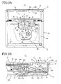
- FIG. 2A is a schematic plan view of the optical disc reproduction apparatus 1
- FIG. 2B is a schematic cross-sectional view of a part of the optical disc reproduction apparatus 1.
- the optical disc reproduction apparatus 1 serves to reproduce images from an optical disc such as DVD (Digital Versatile Disc) and BD (Blu-ray Disc).
- the optical disc reproduction apparatus 1 comprises a main body unit 2, a display unit 3, and a hinge unit 4 via which the display unit 3 is mounted on the main body unit 2.
- the optical disc reproduction apparatus 1 further comprises a cover 5, an inner cover 6, a battery pack 7, and so on.
- the hinge unit 4 comprises: a display-side joint member 41 connected to the display unit 3; a main body-side joint member 42 connected to the main body unit 2; a hinge mechanical unit 43 to pivotally connect the display-side joint member 41 and the main body-side joint member 42 to each other; and so on.
- the hinge unit 4 is a so-called two-axis swivel hinge, in which the hinge mechanical unit 43 connects and allows the display-side joint member 41 and the main body-side joint member 42 to be pivotal to each other about two axes. More specifically, in the optical disc reproduction apparatus 1, the display-side joint member 41 of the hinge unit 4 is connected to the display unit 3, while the main body-side joint member 42 of the hinge unit 4 is connected to the main body unit 2, so as to allow the display unit 3 to be pivotal relative to the main body unit 2 about two axes.
- the main body unit 2 comprises: a control board 21 for controlling the operation of the optical disc reproduction apparatus 1; an optical disc reading unit 22 for reading recorded data from an optical disc; a main body case 23 for housing the control board 21 and the optical disc reading unit 22; a hinge connecting portion 24 to be connected to the main body-side joint member 42 of the hinge unit 4; and so on.
- the main body unit 2 further comprises a hinge housing portion 25 formed therein for housing the main body-side joint member 42 of the hinge unit 4.
- the optical disc reading unit 22 comprises a spindle motor 22a coupled to the optical disc for rotating the optical disc, and an optical pickup head 22b for reading data recorded on the optical disc.
- the main body case 23 comprises a lower case 23a corresponding to (or more specifically, occupying) a lower part of the main body case 23, and an upper case 23b corresponding to (or more specifically, occupying) an upper part of the main body case 23, in which the lower case 23a and the upper case 23b are connected to each other.
- the control board 21 is arranged parallel to a lower surface (bottom surface) of the main body case 23, while the optical disc reading unit 22 is arranged above the control board 21.
- a part of the optical disc reading unit 22 including the spindle motor 22a and the optical pickup head 22b is arranged to face a reading opening 23c formed in the upper case 23b so as to make it possible to read recorded data from the optical disc which is mounted on the optical disc reading unit 22 from outside the main body case 23.
- the hinge connecting portion 24 is provided in the hinge housing portion 25.
- the hinge housing portion 25 is recessed inside its periphery in the main body case 23, and has an opening facing outward from the main body case 23, and is further formed by the shape of the main body case 23.
- the opening of the hinge housing portion 25 is larger than the main body-side joint member 42 of the hinge unit 4, and has an area such that the main body-side joint member 42 of the hinge unit 4 can be introduced into the hinge housing portion 25 from outside the main body case 23 and connected to the hinge connecting portion 24 in a state where the upper case 23b and the lower case 23a of the main body case 23 are connected to each other (i.e. a state where the main body unit 2 is already assembled).
- the hinge housing portion 25 is recessed downward (toward the lower case 23a) from its periphery in the upper case 23b of the main body case 23, and has an opening facing outward from the main body case 23. Further, the hinge housing portion 25 is formed by the shape of the recess in the upper case 23b of the main body case 23.
- the hinge connecting portion 24 is provided on a bottom portion of the hinge housing portion 25. In the present embodiment, the hinge connecting portion 24 is integrally formed with the upper case 23b of the main body case 23.
- the main body-side joint member 42 of the hinge unit 4, while housed in the hinge housing portion 25, is connected to the hinge connecting portion 24 by screwing with hinge mounting screws 49.
- the opening of the hinge housing portion 25 has an area, such as having a diameter equal to or greater than 10 mm, such that a tool for screwing each hinge mounting screw 49 on the head side of the hinge mounting screw 49 can be introduced through the opening of the hinge housing portion 25.
- the control board 21 described above has connectors 27a, 27b provided thereon for connecting electrical wirings 9a, 9b, which are connected to the display unit 3, to the control board 21.
- the connectors 27a, 27b are located on portions of the control board 21 which project to the hinge housing portion 25 from the position of a wiring opening 23d formed in the upper case 23b of the main body case 23, so that the connectors 27a, 27b are located in the hinge housing portion 25.
- the electrical wirings 9a, 9b which extend inside the hinge unit 4 have one ends connected to a circuit board (not shown) in the display unit 3, and have the other ends connected to the connectors 27a, 27b.
- the display unit 3 serves to display images, and comprises a liquid crystal panel 31 for displaying images, a display case 32 for housing the liquid crystal panel 31, and so on.
- the display case 32 comprises a front case 32a corresponding to (more specifically, occupying) a front part of the display case 32, and a rear case 32b corresponding to (more specifically, occupying) a rear part of the display case 32, in which the front case 32a and the rear case 32b are connected to each other.
- the liquid crystal panel 31 faces a display opening 32c formed in the front case 32a.
- the display unit 3 displays images based on recorded data read by the optical disc reading unit 22 from the optical disc.
- the display-side joint member 41 of the hinge unit 4 described above is connected to a hinge mounting portion (not shown) provided on an inner surface of the rear case 32b of the display case 32.
- the cover 5 serves to cover the opening of the hinge housing portion 25.
- the cover 5 is attached to the upper case 23b of the main body case 23 to cover the opening of the hinge housing portion 25 while the display-side joint member 41 and the hinge mechanical unit 43 of the hinge unit 4 are located outside the main body case 23.
- the cover 5 is attached to the upper case 23b by screwing with cover mounting screws 69.
- the inner cover 6 is pivotally supported by the upper case 23b of the main body case 23 so as to be able to open/close an optical disc mounting area of the main body unit 2 (i.e. area where the optical disc is present when the optical disc is mounted on the spindle motor 22a of the optical disc reading unit 22).
- the battery pack 7 serves to supply power to the optical disc reproduction apparatus 1.
- the battery pack 7 is designed to be attachable and detachable to and from the main body unit 2 (lower case 23a of the main body case 23).
- the battery pack 7 has a built-in secondary battery so as to supply the power of the secondary battery to the main body unit 2 when attached to the main body unit 2.
- the display unit 3 is connected and assembled with the hinge unit 4. More specifically, while the electrical wirings 9a, 9b are allowed to extend inside the hinge unit 4, and the front case 32a and the rear case 32b of the display case 32 are separate from each other, one ends of the electrical wirings 9a, 9b are connected to the circuit board (not shown) of the display unit 3, and the display-side joint member 41 of the hinge unit 4 is connected to the hinge mounting portion (not shown) provided on the inner surface of the rear case 32b. Further, the front case 32a and the rear case 32b are connected to each other to sandwich the liquid crystal panel 31 and the circuit board therebetween so as to house the liquid crystal panel 31 and the circuit board in the display case 32.
- the upper case 23b and the lower case 23a of the main body case 23 are connected to each other to sandwich the circuit board 21 and the optical disc reading unit 22 so as to assemble the main body unit 2 housing the control board 21 and the optical disc reading unit 22 therein.
- the hinge unit 4 is connected to the main body unit 2. More specifically, the main body-side joint member 42 of the hinge unit 4 connected to the display unit 3 is introduced into the hinge housing portion 25 through the opening of the hinge housing portion 25 from outside the main body case 23 of the main body unit 2 which has been assembled (i.e. which has the upper case 23b and the lower case 23a connected to each other).
- the main body-side joint member 42 of the hinge unit 4 is connected to the hinge connecting portion 24 of the main body unit 2 by screwing with the hinge mounting screws 49. Further, the other ends of the electrical wirings 9a, 9b extending inside the hinge unit 4 are connected to the connectors 27a, 27b provided on the control board 21. Subsequently, the cover 5 is attached to the main body unit 2. More specifically, the cover 5 is attached to the upper case 23b of the main body case 23 by screwing with the cover mounting screws 69. Finally, the inner cover 6 is attached to the main body unit 2. Thus, the optical disc reproduction apparatus 1 is completed and assembled.
- the thus structured optical disc reproduction apparatus 1 makes it possible to introduce the main body-side joint member 42 of the hinge unit 4 into the hinge housing portion 25 from outside the main body case 23 (through the opening of the hinge housing portion 25) and to connect the main body-side joint member 42 to the hinge connecting portion 24 of the main body unit 2 in a state where the upper case 23b and the lower case 23a of the main body case 23 are connected to each other (i.e. a state where the main body unit 2 is already assembled).
- the hinge unit 4 can be connected to the main body unit 2 in a state where the main body unit 2 is already assembled (i.e. a state where the upper case 23b and the lower case 23a of the main body case 23 are already connected to each other), making it possible to achieve high assembling efficiency.
- the main body-side joint member 42 of the hinge unit 4 is housed in the hinge housing portion 25, which is recessed downward from its periphery in the main body case 23, so that the optical disc reproduction apparatus 1 can be kept thin, and can be easily assembled, making it possible to prevent occurrence of damages and failures.
- the main body case 23 is not required to be reversed or inclined, thus eliminating the need for a table or a tool for exclusive use.
- the opening of the hinge housing portion 25 has an area, such as having a diameter equal to or greater than 10 mm, such that a tool for screwing each hinge mounting screw 49 on the head side of the hinge mounting screw 49 can be introduced through the opening of the hinge housing portion 25.
- the main body-side joint member 42 of the hinge unit 4 can be easily connected by screwing to the hinge connecting portion 24 of the main body unit 2, making it possible to further increase the assembling efficiency.
- the connectors 27a, 27b are provided on the control board 21, and are further located in the hinge housing portion 25, so that the electrical wirings 9a, 9b to be connected to the display unit 3 can be easily connected to the control board 21, making it possible to further increase the assembling efficiency.
- the cover 5 covers the opening of the hinge housing portion 25, so that the cover 5 can cover the hinge connecting portion 24 of the main body unit 2 and the main body-side joint member 42 of the hinge unit 4. This makes it possible to improve the design of the main body unit 2, and hence of the optical disc reproduction apparatus 1.
- the hinge connecting portion of the main body unit is not necessarily formed integrally with the upper case of the main body case, but can be formed separately from the main body case so as to be mounted on the upper case of the main body case.
- the hinge housing portion of the main body unit is not necessarily formed by the shape of the recess in upper case of the main body case, but can be formed by a space in the main body case and an opening provided in the upper case of the main body case.
- the hinge connecting portion of the main body unit can be formed on an inner surface of the lower case of the main body case, or can be integrally formed with the lower case of the main body case, or alternatively can be formed separately from the main body case so as to be mounted on the lower case of the main body case.
Landscapes
- Engineering & Computer Science (AREA)
- Computer Hardware Design (AREA)
- Theoretical Computer Science (AREA)
- Physics & Mathematics (AREA)
- General Engineering & Computer Science (AREA)
- Human Computer Interaction (AREA)
- General Physics & Mathematics (AREA)
- Mathematical Physics (AREA)
- Casings For Electric Apparatus (AREA)
Abstract
Description
- The present invention relates to an electronic apparatus having a function to display images.
- In some of conventional electronic apparatus having a function to display images, a display unit for displaying images is mounted on a main body unit via a hinge unit, in which the display unit can pivot relative to the main body unit (for example, refer to Japanese Laid-open Patent Publications
2003-152357 2004-162888 2007-328529 2007-300440 PCT Application 2007-535224 - In other words, in the conventional electronic apparatus, the hinge unit cannot be connected to the main body unit in a state where the upper case and the lower case of the main body case are connected to each other. More specifically, the hinge unit can be connected to the main body unit only when the upper case and the lower case of the main body case are separated. Thus, the conventional electronic apparatus is assembled such that the hinge unit is connected to the hinge connecting portion in the inner side of the main body unit (upper case or lower case) before connecting the upper and lower cases of the main body case (i.e. before assembling the main body unit), and thereafter the upper and lower cases are connected to each other.
- However, the requirement that the hinge unit be connected to the hinge connecting portion in the side of the main body case (upper case or lower case) before connecting the upper and lower cases, and thereafter the upper and lower cases be connected to each other, when assembling the conventional electronic apparatus as described above, causes problems. First, it causes low assembling efficiency. Second, it causes significant difficulty in assembling, so that damages and failures are likely to occur. Third, the main body case is required to be reversed or inclined when connecting the hinge unit to the main body case, resulting in the requirement of a table or a tool for exclusive use.
- An object of the present invention is to provide an electronic apparatus with high assembling efficiency.
- According to the present invention, this object is achieved by an electronic apparatus comprising a main body unit, a hinge unit and a display unit for displaying images which is mounted on the main body unit via the hinge unit. The hinge unit comprises: a display-side joint member connected to the display unit; a main body-side joint member connected to the main body unit; and a hinge mechanical unit to pivotally connect the display-side joint member and the main body-side joint member to each other. The main body unit comprises: a control board; a main body case for housing the control board; and a hinge connecting portion to be connected to the main body-side joint member of the hinge unit. The main body case comprises a lower case corresponding to a lower part of the main body case, and an upper case corresponding to an upper part of the main body case and connected to the lower case. The main body unit further comprises a hinge housing portion formed therein for housing the main body-side joint member of the hinge unit, the hinge connecting portion being provided in the hinge housing portion. The hinge housing portion is recessed downward from its periphery in the main body case, and has an opening facing outward from the main body case. Further, the opening of the hinge housing portion has an area such that the main body-side joint member of the hinge unit can be introduced into the hinge housing portion from outside the main body case and connected to the hinge connecting portion in a state where the upper case and the lower case of the main body case are connected to each other.
- The thus structured electronic apparatus according to the present invention makes it possible to introduce the main body-side joint member of the hinge unit into the hinge housing portion from outside the main body case (through the opening of the hinge housing portion) and to connect the main body-side joint member to the hinge connecting portion of the main body unit in a state where the upper case and the lower case of the main body case are connected to each other (i.e. a state where the main body unit is already assembled). Thus, when assembling the electronic apparatus, the hinge unit can be connected to the main body unit in a state where the main body unit is already assembled (i.e. a state where the upper case and the lower case of the main body case are already connected to each other), making it possible to achieve high assembling efficiency. In addition, the main body-side joint member of the hinge unit is housed in the hinge housing portion, which is recessed downward from its periphery in the main body case, so that the electronic apparatus can be kept thin, and can be easily assembled, making it possible to prevent occurrence of damages and failures. Further, when connecting the hinge unit to the main body case, the main body case is not required to be reversed or inclined, thus eliminating the need for a table or a tool for exclusive use.
- Preferably, the main body-side joint member of the hinge unit is connected to the hinge connecting portion with a hinge mounting screw, and the opening of the hinge housing portion has an area such that a tool for screwing the hinge mounting screw on the head side of the hinge mounting screw can be introduced through the opening of the hinge housing portion. This preferred mode makes it possible that the main body-side joint member of the hinge unit can be easily connected by screwing to the hinge connecting portion of the main body unit, making it possible to further increase the assembling efficiency.
- Further preferably, the control board has a connector provided thereon for connecting an electrical wiring connected to the display unit to the control board, and the connector is housed in the hinge housing portion. This preferred mode makes it possible that the electrical wiring to be connected to the display unit can be easily connected to the control board, making it possible to further increase the assembling efficiency.
- Yet further preferably, the electronic apparatus further comprises a cover attached to the main body case for covering the opening of the hinge housing portion while the display-side joint member and the hinge mechanical unit of the hinge unit are located outside the main body case. This preferred mode makes it possible that the cover can cover the hinge connecting portion of the main body unit and the main body-side joint member of the hinge unit, making it possible to improve the design of the main body unit.
- Still further preferably, the main body unit further comprises an optical disc reading unit for reading recorded data from an optical disc, wherein the main body case houses the control board and the optical disc reading unit, and the display unit displays images based on recorded data read from the optical disc. This preferred mode makes it possible to achieve the same effects as those of the present invention described above in the case where the electronic apparatus serves to display images based on recorded data read from an optical disc.
- While the novel features of the present invention are set forth in the appended claims, the present invention will be better understood from the following detailed description taken in conjunction with the drawings.
- The present invention will be described hereinafter with reference to the annexed drawings. It is to be noted that all the drawings are shown for the purpose of illustrating the technical concept of the present invention or embodiments thereof, wherein:
-
FIG. 1A is a schematic perspective view, andFIG. 1B is a schematic exploded perspective view of an optical disc reproduction apparatus according to an embodiment of the present invention; and -
FIG. 2A is a schematic plan view of the optical disc reproduction apparatus, whileFIG. 2B is a schematic cross-sectional view of a part of the optical disc reproduction apparatus. - Embodiments of the present invention, as best mode for carrying out the invention, will be described hereinafter with reference to the drawings. The present invention relates to an electronic apparatus. It is to be understood that the embodiments herein are not intended as limiting, or encompassing the entire scope of, the invention. Note that like parts are designated by like reference numerals or characters throughout the drawings.
- An optical
disc reproduction apparatus 1 as an electronic apparatus according to an embodiment of the present invention will be described with reference toFIGs. 1A, 1B andFIGs. 2A, 2B .FIG. 1A is a schematic perspective view, andFIG. 1B is a schematic exploded perspective view of the opticaldisc reproduction apparatus 1.FIG. 2A is a schematic plan view of the opticaldisc reproduction apparatus 1, whileFIG. 2B is a schematic cross-sectional view of a part of the opticaldisc reproduction apparatus 1. The opticaldisc reproduction apparatus 1 serves to reproduce images from an optical disc such as DVD (Digital Versatile Disc) and BD (Blu-ray Disc). - The optical
disc reproduction apparatus 1 comprises a main body unit 2, adisplay unit 3, and ahinge unit 4 via which thedisplay unit 3 is mounted on the main body unit 2. The opticaldisc reproduction apparatus 1 further comprises acover 5, aninner cover 6, abattery pack 7, and so on. Thehinge unit 4 comprises: a display-side joint member 41 connected to thedisplay unit 3; a main body-side joint member 42 connected to the main body unit 2; a hingemechanical unit 43 to pivotally connect the display-side joint member 41 and the main body-side joint member 42 to each other; and so on. Thehinge unit 4 is a so-called two-axis swivel hinge, in which the hingemechanical unit 43 connects and allows the display-side joint member 41 and the main body-side joint member 42 to be pivotal to each other about two axes. More specifically, in the opticaldisc reproduction apparatus 1, the display-sidejoint member 41 of thehinge unit 4 is connected to thedisplay unit 3, while the main body-sidejoint member 42 of thehinge unit 4 is connected to the main body unit 2, so as to allow thedisplay unit 3 to be pivotal relative to the main body unit 2 about two axes. - The main body unit 2 comprises: a
control board 21 for controlling the operation of the opticaldisc reproduction apparatus 1; an opticaldisc reading unit 22 for reading recorded data from an optical disc; amain body case 23 for housing thecontrol board 21 and the opticaldisc reading unit 22; ahinge connecting portion 24 to be connected to the main body-sidejoint member 42 of thehinge unit 4; and so on. The main body unit 2 further comprises ahinge housing portion 25 formed therein for housing the main body-sidejoint member 42 of thehinge unit 4. The opticaldisc reading unit 22 comprises aspindle motor 22a coupled to the optical disc for rotating the optical disc, and anoptical pickup head 22b for reading data recorded on the optical disc. - The
main body case 23 comprises alower case 23a corresponding to (or more specifically, occupying) a lower part of themain body case 23, and anupper case 23b corresponding to (or more specifically, occupying) an upper part of themain body case 23, in which thelower case 23a and theupper case 23b are connected to each other. Thecontrol board 21 is arranged parallel to a lower surface (bottom surface) of themain body case 23, while the opticaldisc reading unit 22 is arranged above thecontrol board 21. A part of the opticaldisc reading unit 22 including thespindle motor 22a and theoptical pickup head 22b is arranged to face areading opening 23c formed in theupper case 23b so as to make it possible to read recorded data from the optical disc which is mounted on the opticaldisc reading unit 22 from outside themain body case 23. - The
hinge connecting portion 24 is provided in thehinge housing portion 25. Thehinge housing portion 25 is recessed inside its periphery in themain body case 23, and has an opening facing outward from themain body case 23, and is further formed by the shape of themain body case 23. The opening of thehinge housing portion 25 is larger than the main body-sidejoint member 42 of thehinge unit 4, and has an area such that the main body-sidejoint member 42 of thehinge unit 4 can be introduced into thehinge housing portion 25 from outside themain body case 23 and connected to thehinge connecting portion 24 in a state where theupper case 23b and thelower case 23a of themain body case 23 are connected to each other (i.e. a state where the main body unit 2 is already assembled). - In the present embodiment, the
hinge housing portion 25 is recessed downward (toward thelower case 23a) from its periphery in theupper case 23b of themain body case 23, and has an opening facing outward from themain body case 23. Further, thehinge housing portion 25 is formed by the shape of the recess in theupper case 23b of themain body case 23. Thehinge connecting portion 24 is provided on a bottom portion of thehinge housing portion 25. In the present embodiment, thehinge connecting portion 24 is integrally formed with theupper case 23b of themain body case 23. The main body-sidejoint member 42 of thehinge unit 4, while housed in thehinge housing portion 25, is connected to thehinge connecting portion 24 by screwing with hinge mounting screws 49. The opening of thehinge housing portion 25 has an area, such as having a diameter equal to or greater than 10 mm, such that a tool for screwing eachhinge mounting screw 49 on the head side of thehinge mounting screw 49 can be introduced through the opening of thehinge housing portion 25. - The
control board 21 described above hasconnectors electrical wirings display unit 3, to thecontrol board 21. Theconnectors control board 21 which project to thehinge housing portion 25 from the position of awiring opening 23d formed in theupper case 23b of themain body case 23, so that theconnectors hinge housing portion 25. Theelectrical wirings hinge unit 4 have one ends connected to a circuit board (not shown) in thedisplay unit 3, and have the other ends connected to theconnectors - The
display unit 3 serves to display images, and comprises aliquid crystal panel 31 for displaying images, adisplay case 32 for housing theliquid crystal panel 31, and so on. Thedisplay case 32 comprises afront case 32a corresponding to (more specifically, occupying) a front part of thedisplay case 32, and arear case 32b corresponding to (more specifically, occupying) a rear part of thedisplay case 32, in which thefront case 32a and therear case 32b are connected to each other. Theliquid crystal panel 31 faces adisplay opening 32c formed in thefront case 32a. Thedisplay unit 3 displays images based on recorded data read by the opticaldisc reading unit 22 from the optical disc. The display-sidejoint member 41 of thehinge unit 4 described above is connected to a hinge mounting portion (not shown) provided on an inner surface of therear case 32b of thedisplay case 32. - The
cover 5 serves to cover the opening of thehinge housing portion 25. Thecover 5 is attached to theupper case 23b of themain body case 23 to cover the opening of thehinge housing portion 25 while the display-sidejoint member 41 and the hingemechanical unit 43 of thehinge unit 4 are located outside themain body case 23. Thecover 5 is attached to theupper case 23b by screwing with cover mounting screws 69. Theinner cover 6 is pivotally supported by theupper case 23b of themain body case 23 so as to be able to open/close an optical disc mounting area of the main body unit 2 (i.e. area where the optical disc is present when the optical disc is mounted on thespindle motor 22a of the optical disc reading unit 22). - When the
inner cover 6 is closed, the optical disc mounting area of the main body unit 2 and a part of thecover 5 are covered by theinner cover 6. When theinner cover 6 is opened, the optical disc mounting area of the main body unit 2 is exposed, making it possible to insert and remove the optical disc into and from the main body unit 2 (i.e. to mount and remove the optical disc on and from thespindle motor 22a). Thebattery pack 7 serves to supply power to the opticaldisc reproduction apparatus 1. Thebattery pack 7 is designed to be attachable and detachable to and from the main body unit 2 (lower case 23a of the main body case 23). Thebattery pack 7 has a built-in secondary battery so as to supply the power of the secondary battery to the main body unit 2 when attached to the main body unit 2. - Next, a method of assembling the optical
disc reproduction apparatus 1 will be described. First, thedisplay unit 3 is connected and assembled with thehinge unit 4. More specifically, while theelectrical wirings hinge unit 4, and thefront case 32a and therear case 32b of thedisplay case 32 are separate from each other, one ends of theelectrical wirings display unit 3, and the display-sidejoint member 41 of thehinge unit 4 is connected to the hinge mounting portion (not shown) provided on the inner surface of therear case 32b. Further, thefront case 32a and therear case 32b are connected to each other to sandwich theliquid crystal panel 31 and the circuit board therebetween so as to house theliquid crystal panel 31 and the circuit board in thedisplay case 32. - On the other hand, the
upper case 23b and thelower case 23a of themain body case 23 are connected to each other to sandwich thecircuit board 21 and the opticaldisc reading unit 22 so as to assemble the main body unit 2 housing thecontrol board 21 and the opticaldisc reading unit 22 therein. - Thereafter, the
hinge unit 4 is connected to the main body unit 2. More specifically, the main body-sidejoint member 42 of thehinge unit 4 connected to thedisplay unit 3 is introduced into thehinge housing portion 25 through the opening of thehinge housing portion 25 from outside themain body case 23 of the main body unit 2 which has been assembled (i.e. which has theupper case 23b and thelower case 23a connected to each other). - Thereafter, the main body-side
joint member 42 of thehinge unit 4 is connected to thehinge connecting portion 24 of the main body unit 2 by screwing with the hinge mounting screws 49. Further, the other ends of theelectrical wirings hinge unit 4 are connected to theconnectors control board 21. Subsequently, thecover 5 is attached to the main body unit 2. More specifically, thecover 5 is attached to theupper case 23b of themain body case 23 by screwing with the cover mounting screws 69. Finally, theinner cover 6 is attached to the main body unit 2. Thus, the opticaldisc reproduction apparatus 1 is completed and assembled. - The thus structured optical
disc reproduction apparatus 1 makes it possible to introduce the main body-sidejoint member 42 of thehinge unit 4 into thehinge housing portion 25 from outside the main body case 23 (through the opening of the hinge housing portion 25) and to connect the main body-sidejoint member 42 to thehinge connecting portion 24 of the main body unit 2 in a state where theupper case 23b and thelower case 23a of themain body case 23 are connected to each other (i.e. a state where the main body unit 2 is already assembled). Thus, when assembling the opticaldisc reproduction apparatus 1, thehinge unit 4 can be connected to the main body unit 2 in a state where the main body unit 2 is already assembled (i.e. a state where theupper case 23b and thelower case 23a of themain body case 23 are already connected to each other), making it possible to achieve high assembling efficiency. - In addition, the main body-side
joint member 42 of thehinge unit 4 is housed in thehinge housing portion 25, which is recessed downward from its periphery in themain body case 23, so that the opticaldisc reproduction apparatus 1 can be kept thin, and can be easily assembled, making it possible to prevent occurrence of damages and failures. Further, when connecting thehinge unit 4 to themain body case 23, themain body case 23 is not required to be reversed or inclined, thus eliminating the need for a table or a tool for exclusive use. Furthermore, the opening of thehinge housing portion 25 has an area, such as having a diameter equal to or greater than 10 mm, such that a tool for screwing eachhinge mounting screw 49 on the head side of thehinge mounting screw 49 can be introduced through the opening of thehinge housing portion 25. Thus, the main body-sidejoint member 42 of thehinge unit 4 can be easily connected by screwing to thehinge connecting portion 24 of the main body unit 2, making it possible to further increase the assembling efficiency. - Furthermore, the
connectors control board 21, and are further located in thehinge housing portion 25, so that theelectrical wirings display unit 3 can be easily connected to thecontrol board 21, making it possible to further increase the assembling efficiency. In addition, thecover 5 covers the opening of thehinge housing portion 25, so that thecover 5 can cover thehinge connecting portion 24 of the main body unit 2 and the main body-sidejoint member 42 of thehinge unit 4. This makes it possible to improve the design of the main body unit 2, and hence of the opticaldisc reproduction apparatus 1. - It is to be noted that the present invention is not limited to the above embodiments, and various modifications are possible within the spirit and scope of the present invention. For example, the hinge connecting portion of the main body unit is not necessarily formed integrally with the upper case of the main body case, but can be formed separately from the main body case so as to be mounted on the upper case of the main body case. Furthermore, the hinge housing portion of the main body unit is not necessarily formed by the shape of the recess in upper case of the main body case, but can be formed by a space in the main body case and an opening provided in the upper case of the main body case. In this case, the hinge connecting portion of the main body unit can be formed on an inner surface of the lower case of the main body case, or can be integrally formed with the lower case of the main body case, or alternatively can be formed separately from the main body case so as to be mounted on the lower case of the main body case.
- The present invention has been described above using presently preferred embodiments, but such description should not be interpreted as limiting the present invention. Various modifications will become obvious, evident or apparent to those ordinarily skilled in the art, who have read the description. Accordingly, the appended claims should be interpreted to cover all modifications and alterations which fall within the spirit and scope of the present invention.
- This application is based on Japanese patent application
2010-001583 filed January 6, 2010
Claims (8)
- An electronic apparatus comprising a main body unit, a hinge unit and a display unit for displaying images which is mounted on the main body unit via the hinge unit,
wherein the hinge unit comprises: a display-side joint member connected to the display unit; a main body-side joint member connected to the main body unit; and a hinge mechanical unit to pivotally connect the display-side joint member and the main body-side joint member to each other,
wherein the main body unit comprises: a control board; a main body case for housing the control board; and a hinge connecting portion to be connected to the main body-side joint member of the hinge unit,
wherein the main body case comprises a lower case corresponding to a lower part of the main body case, and an upper case corresponding to an upper part of the main body case and connected to the lower case,
wherein the main body unit further comprises a hinge housing portion formed therein for housing the main body-side joint member of the hinge unit, the hinge connecting portion being provided in the hinge housing portion,
wherein the hinge housing portion is recessed downward from its periphery in the main body case, and has an opening facing outward from the main body case, and
wherein the opening of the hinge housing portion has an area such that the main body-side joint member of the hinge unit can be introduced into the hinge housing portion from outside the main body case and connected to the hinge connecting portion in a state where the upper case and the lower case of the main body case are connected to each other. - The electronic apparatus according to claim 1,
wherein the main body-side joint member of the hinge unit is connected to the hinge connecting portion with a hinge mounting screw, and
wherein the opening of the hinge housing portion has an area such that a tool for screwing the hinge mounting screw on the head side of the hinge mounting screw can be introduced through the opening of the hinge housing portion. - The electronic apparatus according to claim 2,
wherein the control board has a connector provided thereon for connecting an electrical wiring connected to the display unit to the control board, and
wherein the connector is housed in the hinge housing portion. - The electronic apparatus according to claim 3,
which further comprises a cover attached to the main body case for covering the opening of the hinge housing portion while the display-side joint member and the hinge mechanical unit of the hinge unit are located outside the main body case. - The electronic apparatus according to claim 4,
wherein the main body unit further comprises an optical disc reading unit for reading recorded data from an optical disc,
wherein the main body case houses the control board and the optical disc reading unit, and
wherein the display unit displays images based on recorded data read from the optical disc. - The electronic apparatus according to claim 1,
wherein the control board has a connector provided thereon for connecting an electrical wiring connected to the display unit to the control board, and
wherein the connector is housed in the hinge housing portion. - The electronic apparatus according to claim 1,
which further comprises a cover attached to the main body case for covering the opening of the hinge housing portion while the display-side joint member and the hinge mechanical unit of the hinge unit are located outside the main body case. - The electronic apparatus according to claim 1,
wherein the main body unit further comprises an optical disc reading unit for reading recorded data from an optical disc,
wherein the main body case houses the control board and the optical disc reading unit, and
wherein the display unit displays images based on recorded data read from the optical disc.
Applications Claiming Priority (1)
| Application Number | Priority Date | Filing Date | Title |
|---|---|---|---|
| JP2010001583A JP2011141704A (en) | 2010-01-06 | 2010-01-06 | Electronic apparatus |
Publications (2)
| Publication Number | Publication Date |
|---|---|
| EP2343622A2 true EP2343622A2 (en) | 2011-07-13 |
| EP2343622A3 EP2343622A3 (en) | 2012-11-07 |
Family
ID=43920807
Family Applications (1)
| Application Number | Title | Priority Date | Filing Date |
|---|---|---|---|
| EP10197218A Withdrawn EP2343622A3 (en) | 2010-01-06 | 2010-12-29 | Electronic apparatus for displaying images |
Country Status (3)
| Country | Link |
|---|---|
| US (1) | US20110164369A1 (en) |
| EP (1) | EP2343622A3 (en) |
| JP (1) | JP2011141704A (en) |
Cited By (1)
| Publication number | Priority date | Publication date | Assignee | Title |
|---|---|---|---|---|
| EP2362397A3 (en) * | 2010-02-22 | 2013-07-03 | Funai Electric Co., Ltd. | Electronic apparatus |
Families Citing this family (1)
| Publication number | Priority date | Publication date | Assignee | Title |
|---|---|---|---|---|
| JP5941740B2 (en) * | 2012-04-25 | 2016-06-29 | 富士通株式会社 | Electronic equipment |
Citations (8)
| Publication number | Priority date | Publication date | Assignee | Title |
|---|---|---|---|---|
| JP2003152357A (en) | 2001-11-16 | 2003-05-23 | Lg Electronics Inc | FPC connection structure for electronic equipment and FPC for electronic equipment |
| JP2004162888A (en) | 2002-09-26 | 2004-06-10 | Sharp Corp | Electronic equipment |
| US20060045495A1 (en) * | 2004-08-27 | 2006-03-02 | Prabhune Uday A | Electronic apparatus and program |
| JP2007300440A (en) | 2006-04-28 | 2007-11-15 | Fujitsu Ten Ltd | Display device |
| JP2007535224A (en) | 2003-12-31 | 2007-11-29 | ソニー エリクソン モバイル コミュニケーションズ, エービー | Hinge mechanism having a plurality of rotating shafts for positioning a mobile communication device |
| JP2007328529A (en) | 2006-06-07 | 2007-12-20 | Toshiba Corp | Electronics |
| JP2010001583A (en) | 2008-06-19 | 2010-01-07 | Kuraray Co Ltd | Synthetic fiber bundle for reinforcing cement-mixed banking |
| EP2343707A2 (en) * | 2010-01-06 | 2011-07-13 | Funai Electric Co., Ltd. | Optical disc reproduction apparatus |
Family Cites Families (11)
| Publication number | Priority date | Publication date | Assignee | Title |
|---|---|---|---|---|
| JP2786677B2 (en) * | 1989-06-23 | 1998-08-13 | 株式会社東芝 | Small electronic equipment |
| JP3382073B2 (en) * | 1995-09-19 | 2003-03-04 | 株式会社東芝 | Portable electronic devices |
| US5978210A (en) * | 1997-10-01 | 1999-11-02 | Dell Computer Corporation | Two-piece flex circuit bobbin for portable computers |
| JP3661786B2 (en) * | 2001-11-26 | 2005-06-22 | インターナショナル・ビジネス・マシーンズ・コーポレーション | Computer equipment |
| US6657856B1 (en) * | 2002-07-08 | 2003-12-02 | Lu Sheng-Nan | Hinge for a notebook computer |
| US6788530B2 (en) * | 2002-09-24 | 2004-09-07 | International Business Machines Corporation | User friendly computer equipment, monitor unit, and monitor unit setting base |
| JP4533712B2 (en) * | 2004-09-30 | 2010-09-01 | 株式会社東芝 | Electronics |
| TWI249663B (en) * | 2004-10-15 | 2006-02-21 | Tatung Co Ltd | Rotatable and moveable mechanism |
| JP2007183830A (en) * | 2006-01-06 | 2007-07-19 | Toshiba Corp | Electronics |
| JP4978567B2 (en) * | 2008-06-10 | 2012-07-18 | 富士通株式会社 | Electronics |
| JP4724245B2 (en) * | 2009-12-25 | 2011-07-13 | 株式会社東芝 | Electronics |
-
2010
- 2010-01-06 JP JP2010001583A patent/JP2011141704A/en active Pending
- 2010-12-28 US US12/979,718 patent/US20110164369A1/en not_active Abandoned
- 2010-12-29 EP EP10197218A patent/EP2343622A3/en not_active Withdrawn
Patent Citations (8)
| Publication number | Priority date | Publication date | Assignee | Title |
|---|---|---|---|---|
| JP2003152357A (en) | 2001-11-16 | 2003-05-23 | Lg Electronics Inc | FPC connection structure for electronic equipment and FPC for electronic equipment |
| JP2004162888A (en) | 2002-09-26 | 2004-06-10 | Sharp Corp | Electronic equipment |
| JP2007535224A (en) | 2003-12-31 | 2007-11-29 | ソニー エリクソン モバイル コミュニケーションズ, エービー | Hinge mechanism having a plurality of rotating shafts for positioning a mobile communication device |
| US20060045495A1 (en) * | 2004-08-27 | 2006-03-02 | Prabhune Uday A | Electronic apparatus and program |
| JP2007300440A (en) | 2006-04-28 | 2007-11-15 | Fujitsu Ten Ltd | Display device |
| JP2007328529A (en) | 2006-06-07 | 2007-12-20 | Toshiba Corp | Electronics |
| JP2010001583A (en) | 2008-06-19 | 2010-01-07 | Kuraray Co Ltd | Synthetic fiber bundle for reinforcing cement-mixed banking |
| EP2343707A2 (en) * | 2010-01-06 | 2011-07-13 | Funai Electric Co., Ltd. | Optical disc reproduction apparatus |
Cited By (1)
| Publication number | Priority date | Publication date | Assignee | Title |
|---|---|---|---|---|
| EP2362397A3 (en) * | 2010-02-22 | 2013-07-03 | Funai Electric Co., Ltd. | Electronic apparatus |
Also Published As
| Publication number | Publication date |
|---|---|
| JP2011141704A (en) | 2011-07-21 |
| US20110164369A1 (en) | 2011-07-07 |
| EP2343622A3 (en) | 2012-11-07 |
Similar Documents
| Publication | Publication Date | Title |
|---|---|---|
| US7428145B2 (en) | Electronic apparatus | |
| US20090009955A1 (en) | Electronic apparatus having a connector connecting a disk drive | |
| JP2012128783A (en) | Information processor | |
| US6749507B2 (en) | Entertainment apparatus and monitor device used therein | |
| US20110164369A1 (en) | Electronic apparatus | |
| US20070047189A1 (en) | Electronic apparatus | |
| US20070047197A1 (en) | Electronic apparatus | |
| EP2362397A2 (en) | Electronic apparatus | |
| US20070047191A1 (en) | Electronic apparatus | |
| US8225338B2 (en) | Electronic apparatus | |
| KR20070117504A (en) | Electronics | |
| JPWO2011024316A1 (en) | Electronics | |
| CN212696081U (en) | Image pickup apparatus | |
| US8934230B2 (en) | Portable computer with easy assembly | |
| US8456813B2 (en) | Optical disc reproduction apparatus | |
| JPWO2011024317A1 (en) | Electronics | |
| US8413177B2 (en) | Information-processing equipment | |
| JP4917701B1 (en) | Electronics | |
| JP2011210848A (en) | Electronic equipment device | |
| US7283356B2 (en) | Electronic apparatus | |
| CN102023675B (en) | Video device | |
| JP4221725B2 (en) | Hard disk connector | |
| JPH09114554A (en) | Electronics | |
| US20090039159A1 (en) | Electronic device | |
| JP2007174585A (en) | Cradle device |
Legal Events
| Date | Code | Title | Description |
|---|---|---|---|
| PUAI | Public reference made under article 153(3) epc to a published international application that has entered the european phase |
Free format text: ORIGINAL CODE: 0009012 |
|
| AK | Designated contracting states |
Kind code of ref document: A2 Designated state(s): AL AT BE BG CH CY CZ DE DK EE ES FI FR GB GR HR HU IE IS IT LI LT LU LV MC MK MT NL NO PL PT RO RS SE SI SK SM TR |
|
| AX | Request for extension of the european patent |
Extension state: BA ME |
|
| PUAL | Search report despatched |
Free format text: ORIGINAL CODE: 0009013 |
|
| AK | Designated contracting states |
Kind code of ref document: A3 Designated state(s): AL AT BE BG CH CY CZ DE DK EE ES FI FR GB GR HR HU IE IS IT LI LT LU LV MC MK MT NL NO PL PT RO RS SE SI SK SM TR |
|
| AX | Request for extension of the european patent |
Extension state: BA ME |
|
| RIC1 | Information provided on ipc code assigned before grant |
Ipc: G06F 1/16 20060101AFI20121002BHEP |
|
| 17P | Request for examination filed |
Effective date: 20130318 |
|
| 17Q | First examination report despatched |
Effective date: 20140707 |
|
| STAA | Information on the status of an ep patent application or granted ep patent |
Free format text: STATUS: THE APPLICATION IS DEEMED TO BE WITHDRAWN |
|
| 18D | Application deemed to be withdrawn |
Effective date: 20141118 |