EP2343570A1 - Pulse radar range profile motion compensation - Google Patents
Pulse radar range profile motion compensation Download PDFInfo
- Publication number
- EP2343570A1 EP2343570A1 EP10250040A EP10250040A EP2343570A1 EP 2343570 A1 EP2343570 A1 EP 2343570A1 EP 10250040 A EP10250040 A EP 10250040A EP 10250040 A EP10250040 A EP 10250040A EP 2343570 A1 EP2343570 A1 EP 2343570A1
- Authority
- EP
- European Patent Office
- Prior art keywords
- range
- pulse
- range rate
- receiver samples
- estimate
- Prior art date
- Legal status (The legal status is an assumption and is not a legal conclusion. Google has not performed a legal analysis and makes no representation as to the accuracy of the status listed.)
- Ceased
Links
- 238000000034 method Methods 0.000 claims abstract description 59
- 238000012937 correction Methods 0.000 claims abstract description 40
- 230000006835 compression Effects 0.000 claims description 4
- 238000007906 compression Methods 0.000 claims description 4
- 238000012935 Averaging Methods 0.000 claims description 3
- 238000005070 sampling Methods 0.000 claims description 3
- 230000001419 dependent effect Effects 0.000 claims description 2
- 230000000694 effects Effects 0.000 description 6
- GNFTZDOKVXKIBK-UHFFFAOYSA-N 3-(2-methoxyethoxy)benzohydrazide Chemical compound COCCOC1=CC=CC(C(=O)NN)=C1 GNFTZDOKVXKIBK-UHFFFAOYSA-N 0.000 description 2
- FGUUSXIOTUKUDN-IBGZPJMESA-N C1(=CC=CC=C1)N1C2=C(NC([C@H](C1)NC=1OC(=NN=1)C1=CC=CC=C1)=O)C=CC=C2 Chemical compound C1(=CC=CC=C1)N1C2=C(NC([C@H](C1)NC=1OC(=NN=1)C1=CC=CC=C1)=O)C=CC=C2 FGUUSXIOTUKUDN-IBGZPJMESA-N 0.000 description 2
- 238000001914 filtration Methods 0.000 description 2
- 239000011159 matrix material Substances 0.000 description 2
- 230000000717 retained effect Effects 0.000 description 2
- 238000000605 extraction Methods 0.000 description 1
- 238000012986 modification Methods 0.000 description 1
- 230000004048 modification Effects 0.000 description 1
- 238000003672 processing method Methods 0.000 description 1
Images


Classifications
-
- G—PHYSICS
- G01—MEASURING; TESTING
- G01S—RADIO DIRECTION-FINDING; RADIO NAVIGATION; DETERMINING DISTANCE OR VELOCITY BY USE OF RADIO WAVES; LOCATING OR PRESENCE-DETECTING BY USE OF THE REFLECTION OR RERADIATION OF RADIO WAVES; ANALOGOUS ARRANGEMENTS USING OTHER WAVES
- G01S13/00—Systems using the reflection or reradiation of radio waves, e.g. radar systems; Analogous systems using reflection or reradiation of waves whose nature or wavelength is irrelevant or unspecified
- G01S13/02—Systems using reflection of radio waves, e.g. primary radar systems; Analogous systems
- G01S13/06—Systems determining position data of a target
- G01S13/08—Systems for measuring distance only
- G01S13/10—Systems for measuring distance only using transmission of interrupted, pulse modulated waves
- G01S13/26—Systems for measuring distance only using transmission of interrupted, pulse modulated waves wherein the transmitted pulses use a frequency- or phase-modulated carrier wave
- G01S13/28—Systems for measuring distance only using transmission of interrupted, pulse modulated waves wherein the transmitted pulses use a frequency- or phase-modulated carrier wave with time compression of received pulses
-
- G—PHYSICS
- G01—MEASURING; TESTING
- G01S—RADIO DIRECTION-FINDING; RADIO NAVIGATION; DETERMINING DISTANCE OR VELOCITY BY USE OF RADIO WAVES; LOCATING OR PRESENCE-DETECTING BY USE OF THE REFLECTION OR RERADIATION OF RADIO WAVES; ANALOGOUS ARRANGEMENTS USING OTHER WAVES
- G01S13/00—Systems using the reflection or reradiation of radio waves, e.g. radar systems; Analogous systems using reflection or reradiation of waves whose nature or wavelength is irrelevant or unspecified
- G01S13/02—Systems using reflection of radio waves, e.g. primary radar systems; Analogous systems
- G01S13/50—Systems of measurement based on relative movement of target
- G01S13/505—Systems of measurement based on relative movement of target using Doppler effect for determining closest range to a target or corresponding time, e.g. miss-distance indicator
-
- G—PHYSICS
- G01—MEASURING; TESTING
- G01S—RADIO DIRECTION-FINDING; RADIO NAVIGATION; DETERMINING DISTANCE OR VELOCITY BY USE OF RADIO WAVES; LOCATING OR PRESENCE-DETECTING BY USE OF THE REFLECTION OR RERADIATION OF RADIO WAVES; ANALOGOUS ARRANGEMENTS USING OTHER WAVES
- G01S7/00—Details of systems according to groups G01S13/00, G01S15/00, G01S17/00
- G01S7/02—Details of systems according to groups G01S13/00, G01S15/00, G01S17/00 of systems according to group G01S13/00
- G01S7/41—Details of systems according to groups G01S13/00, G01S15/00, G01S17/00 of systems according to group G01S13/00 using analysis of echo signal for target characterisation; Target signature; Target cross-section
- G01S7/415—Identification of targets based on measurements of movement associated with the target
Definitions
- the invention relates to a pulse radar range profile motion compensation method and to a method of providing a radar range profile of a moving target.
- NCTR non-cooperative target recognition
- the motion of the target must be corrected for prior to generating an HRR profile otherwise the effect of the motion of the target on the radar echo signals will result in the HRR profile being corrupted.
- Effects observed in HRR profile of moving targets typically involve combinations of peak broadening (which leads to loss of resolution), range shifting of peaks and loss of dynamic range. Since the target is already being tracked one method of compensating for the motion of the target involves obtaining an estimate of the target range rate from the radar tracker and using the range rate estimate to apply motion compensation to receiver samples obtained from the radar echo signals.
- a slightly incorrect target range rate can result in significant corruption of the HRR profile of the target.
- a pulse radar range profile motion compensation method comprising:
- the method is thus able to provide a range rate correction to the target range rate enabling improved motion compensation to be applied to the receiver samples.
- the pulse radar signal comprises a frequency coded waveform and following step iv. the method further comprises applying a pulse compression to the receiver samples, identifying a range cell corresponding to a maximum power of the pulse compressed receiver samples and, for each pulse, selecting a receiver sample corresponding to the identified range cell.
- the maximum power is identified across all pulses, all frequency steps and all receiver samples. This takes account of any potential interference effects between multiple scatterers in the target which may produce a null at a particular frequency step.
- the estimate of the range rate of the target is preferably acquired from a radar tracker tracking the target. A good, real-time estimate of the target range rate can therefore be provided.
- step iii. comprises applying a complex multiplication of exp 4 ⁇ ⁇ ⁇ f Tx c ⁇ t p ⁇ R ⁇ , where tp is the time of a pulse p since the start of the look, to the receiver samples.
- step iv. comprises generating a Fourier transform of the receiver samples of step iii. and multiplying the Fourier transform by a phase ramp corresponding to the target range shift, 1 2 ⁇ t p ⁇ R ⁇ , since the start of the look and subsequently generating an inverse Fourier transform of the Fourier transformed receiver samples.
- a range walk correction of less than a whole range cell can thus be applied.
- the Doppler filter preferably comprises outputs at Doppler frequencies in the range - 1 ⁇ 2 f PRF to 1 ⁇ 2 f PRF and spaced by f PRF P .
- Step v. preferably comprises multiplying the receiver samples by a windowing function and generating a Fourier transform of the resulting receiver samples.
- the windowing function comprises a low sidelobe Dolph-Chebychev windowing function.
- the Fourier transforms comprise discrete Fourier transforms.
- the magnitude of the range rate correction, ⁇ does not exceed cf PRF 2 ⁇ P ⁇ f Tx .
- the radar signal preferably comprises a stepped-frequency waveform comprising a second plurality, Q, of frequency steps, each frequency step comprising a said plurality, P, of pulses.
- the motion compensation is thus able to be performed within a single frequency step.
- step iii. comprises applying a complex multiplication of exp 4 ⁇ ⁇ ⁇ f Tx c ⁇ t pq ⁇ R ⁇ , where tpq is the time of a pulse p of a frequency step q since the start of the look, to the receiver samples.
- step iv. comprises multiplying the Fourier transform by a phase ramp corresponding to the target range shift, 1 2 ⁇ t pq ⁇ R ⁇ , since the start of the look.
- step v. further comprises averaging the Doppler filter output over the frequency steps and step vi. comprises identifying the peak Doppler frequency by interpolating the averaged Doppler filter output in the region - 2 ⁇ f PRF P ⁇ to ⁇ 2 ⁇ f PRF P . Looking for the peak Doppler frequency in this restricted region reduces the possibility of the peak Doppler frequency being incorrectly identified as a jet engine modulation Doppler frequency in the Doppler filter output.
- Step viii. preferably comprises:
- the range rate correction can therefore be iteratively determined to obtain a more accurate range rate estimate.
- a radar range profile of a moving target comprising:
- the method enables a radar range profile to be generated of a moving target with improved motion compensation and therefore less corruption in the HRR profile.
- the pulse radar signal comprises a frequency coded waveform and following step e. the method further comprises applying a pulse compression to the receiver samples, identifying a range cell corresponding to a maximum power of the pulse compressed receiver samples and, for each pulse, selecting a receiver sample corresponding to the identified range cell.
- the maximum power is identified across all pulses, all frequency steps and all receiver samples. This takes account of any potential interference effects between multiple scatterers in the target which may produce a null at a particular frequency step.
- the estimate of the range rate of the target is preferably acquired from a radar tracker tracking the target. A good, real-time estimate of the target range rate can therefore be provided.
- step d. comprises applying a complex multiplication of exp 4 ⁇ ⁇ ⁇ f Tx c ⁇ t p ⁇ R ⁇ , where t p is the time of a pulse p since the start of the look, to the receiver samples.
- step e. comprises generating a Fourier transform of the receiver samples of step d. and multiplying the Fourier transform by a phase ramp corresponding to the target range shift, 1 2 ⁇ t p ⁇ R ⁇ , since the start of the look and subsequently generating an inverse Fourier transform of the Fourier transformed receiver samples.
- a range walk correction of less than a whole range cell can thus be applied.
- the Doppler filter preferably comprises outputs at Doppler frequencies in the range - 1 ⁇ 2 f PRF to 1 ⁇ 2 f PRF and spaced by f PRF P .
- Step g. preferably comprises multiplying the receiver samples by a windowing function and generating a Fourier transform of the resulting receiver samples.
- the windowing function comprises a low sidelobe Dolph-Chebychev windowing function.
- the Fourier transforms comprise discrete Fourier transforms.
- the magnitude of the range rate correction, ⁇ v does not exceed cf PRF 2 ⁇ P ⁇ f Tx .
- the pulse radar signal preferably comprises a stepped-frequency waveform comprising a second plurality, Q, of frequency steps, each frequency step comprising a said plurality, P, of pulses.
- the motion compensation is thus able to be performed within a single frequency step.
- step d. comprises applying a complex multiplication of exp 4 ⁇ ⁇ ⁇ f Tx c ⁇ t pq ⁇ R ⁇ , where t pq is the time of a pulse p of a frequency step q since the start of the look, to the receiver samples.
- step e. comprises multiplying the Fourier transform by a phase ramp corresponding to the target range shift, 1 2 ⁇ t pq ⁇ R ⁇ , since the start of the look.
- step f. further comprises averaging the Doppler filter output over the frequency steps and step g. comprises identifying the peak Doppler frequency by interpolating the averaged Doppler filter output in the region - 2 ⁇ f PRF P ⁇ to ⁇ 2 ⁇ f PRF P . Looking for the peak Doppler frequency in this restricted region reduces the possibility of the peak Doppler frequency being incorrectly identified as a jet engine modulation Doppler frequency in the Doppler filter output.
- Step i. preferably comprises:
- the range rate correction can therefore be iteratively determined to obtain a more accurate range rate estimate and an improved HRR profile can be provided.
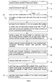
- a first embodiment of the invention provides a pulse radar range profile motion compensation method 10 having the steps shown in Figure 1 .
- the method 10 comprises:
- the method 10 may be used to effect motion compensation for a moving target illuminated with any pulse radar signal for which the carrier frequency and phase do not vary over the pulses, P, used to implement the method 10.
- the method 10 may be used for both short pulses and frequency coded waveforms.
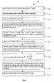
- a second embodiment of the invention provides a pulse radar range profile motion compensation method 40 having the steps shown in Figure 2 .
- the method 40 is substantially the same as the method 10 of Figure 1 , with the following modifications.
- the same reference numbers are retained for corresponding features.
- the radar signal comprises a stepped-frequency signal comprising a second plurality, Q, of frequency steps, each comprising the said plurality, P, of pulses.
- the radar signal comprises a frequency coded waveform in this example, with the pulses being chirp pulses.
- the receiver samples comprise complex receiver samples.
- the motion compensation method 40 is performed on the pulses of a single frequency step.
- the range rate estimate is acquired from a radar tracker unit, which will typically provide a range rate estimate that is correct to within a few meters per second.
- Step iii. comprises applying a complex multiplication 42 of exp 4 ⁇ ⁇ ⁇ f Tx c ⁇ t pq ⁇ R ⁇ to the receiver samples.
- t pq identifies a pulse a pulse p of the said plurality, P, of pulses of a frequency step q of the second plurality, Q, of frequency steps in terms of the timing of pulse since the start of the look. This corrects for phase walk of the pulses.
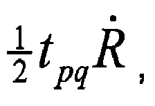
- Step iv. comprises multiplying the Fourier transform resulting from step iii. by a phase ramp corresponding to the target range shift, 1 2 ⁇ t pq ⁇ R ⁇ , for a pulse p of frequency step q since the start of the look. This corrects for range walk of the receiver samples and enables range walk of less than a whole range cell to be corrected for.
- the method 40 of this embodiment further comprises applying a pulse compression to the receiver samples.
- This signal processing method will be well know to the person skilled in the art and so it will not be described in detail here.
- the method 40 further comprises identifying a range cell corresponding to a maximum power of the pulse compressed receiver samples and, for each pulse, selecting a receiver sample corresponding to the identified range cell.
- the maximum power is taken over all pulses, all frequency steps and all receiver samples to take account of any interference effects between multiple scatterers in the target which can result in a null at a particular frequency step.
- a receiver sample is selected from the vector of receiver samples at the range cell corresponding to the maximum power. The selected samples are formed into a PxQ matrix.
- the Doppler filtering step 46 of this embodiment comprises multiplying the matrix of receiver samples by a windowing function and subsequently generating a Fourier transform of the resulting windowed set of receiver samples.
- the windowing function comprises a Dolph-Chebychev windowing function having low sidelobes, of the order of 40dB.
- the Doppler filter provides outputs at Doppler frequencies in the range ⁇ 1 ⁇ 2 f PRF to 1 ⁇ 2 f PRF and spaced by f PRF P .
- the Doppler filter output is averaged over the frequency steps and the peak Doppler frequency is identified 24 by interpolating the averaged Doppler filter output in the - 2 ⁇ f PRF P ⁇ to ⁇ 2 ⁇ f PRF P . Looking for the peak Doppler frequency in this restricted region reduces the possibility of the peak Doppler frequency being incorrectly identified as a jet engine modulation (JEM) Doppler frequency in the Doppler filter output.
- JEM jet engine modulation
- the peak Doppler frequency is assumed to correspond to the skin return of the target and therefore the peak Doppler frequency can be used to determine the range rate correction.
- Step viii corresponds to a single iteration of calculating a range rate correction and a corrected range rate estimate.
- the method 40 may be extended to include one or more additional iterations, with the following steps:
- the range rate correction can therefore be iteratively determined to obtain a more accurate range rate estimate.
- the receiver samples form a discrete series and it will therefore be appreciated that discrete Fourier transforms and inverse discrete Fourier transforms are used.
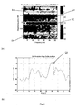
- Figures 3 and 4 illustrate the improvement in an HRR profile which may be obtained by using the method 40.
- a moving target is illuminated in both instances with a stepped-frequency pulse radar signal having a starting carrier frequency, f Tx , of 2708.2MHz, a frequency step, ⁇ f, of 3.2MHz, and a pulse repetition frequency, f PRF , of 2.5kHz.
- the pulse radar signal comprises 32 frequency steps, Q, each comprising 32 pulses, P, each pulse having a chirp bandwidth, B, of -4.5MHz and a duration, ⁇ , of 25.6 ⁇ s.
- Figure 3(a) shows the Doppler filter output 50 from step v., the receiver samples being processed by applying steps i. to v. and ix., i.e. the steps of the method 40 without applying steps vi. to viii. to calculate a range rate correction. It can be seen that the skin return 52 is offset from 0Hz, which is where the skin return would be located if the target was not moving. JEM lines 54 are clearly visible above and below the skin return.
- Figure 3(b) shows a Classical HRR profile 56 obtained from the receiver samples obtained after the Doppler filtering step. As can be seen, the HRR profile is significantly degraded.
- the method of producing a Classical HRR profile will be well known to the person skilled in the art and so it will not be described in detail here.
- Figure 4(a) shows the Doppler filter output 60 from step v. following application of steps i. to viii. of the method 40, that is to say, following correction of the range rate estimate.
- the skin return 62 is clearly centred about 0Hz.
- JEM lines 64 are again visible above and below the skin return.
- Figure 4(b) shows a Classical HRR profile 66 generated from the output signal of step ix. of the method 40. As can be seen, the HRR profile is much improved as compared to that shown in Figure 3(b) and the method 40 has clearly compensated for bulk motion of the target.
- the steps of a method 70 of providing a radar range profile of a moving target according to third embodiment of the invention are shown in Figure 5 .
- the method 70 comprises many of the steps of the pulse radar range profile motion compensation method 10 of Figure 1 and the same reference numbers are retained for corresponding steps.
- the method 70 comprises the steps:
- the method 70 of this embodiment may alternatively comprise the steps of the pulse radar range profile motion compensation method 40 of Figure 2 .
- the method 70 of this embodiment is used to generate the HRR profile of Figure 4(b) .
Landscapes
- Engineering & Computer Science (AREA)
- Radar, Positioning & Navigation (AREA)
- Remote Sensing (AREA)
- Computer Networks & Wireless Communication (AREA)
- Physics & Mathematics (AREA)
- General Physics & Mathematics (AREA)
- Radar Systems Or Details Thereof (AREA)
Abstract
A pulse radar range profile motion compensation method 10 comprises: acquiring receiver samples 12; acquiring an estimate of the range rate of a target 14; removing an additional phase acquired by the echo signals; removing a shift in range cells of the receiver samples 18; applying a pulse Doppler filter 22; identifying the peak Doppler frequency and calculating a shift from zero of the peak Doppler frequency 24; calculating a range rate correction 26; adding the range rate correction to the estimate of the range rate and repeating the removal of the additional phase 16 and the shift in range cells 18, and using the new range rate estimate to obtain motion compensated receiver samples 28; and generating an output signal indicative of the motion compensated receiver samples for generating a range profile 30.
Description
- The invention relates to a pulse radar range profile motion compensation method and to a method of providing a radar range profile of a moving target.
- There is a need for radar systems to offer non-cooperative target recognition (NCTR) capability, in order to enable rapid and reliable identification of targets. In practical terms, this consists of a capability to generate High Range Resolution (HRR) profiles of targets that are already being tracked. Feature extraction algorithms can then be applied to the HRR profiles, which enable a classifier to identify a target in conjunction with a database of known targets. The success of NCTR capabilities is very much dependent on the quality of the HRR profiles obtained for both reference targets and during operation.
- For a moving target, the motion of the target must be corrected for prior to generating an HRR profile otherwise the effect of the motion of the target on the radar echo signals will result in the HRR profile being corrupted. Effects observed in HRR profile of moving targets typically involve combinations of peak broadening (which leads to loss of resolution), range shifting of peaks and loss of dynamic range. Since the target is already being tracked one method of compensating for the motion of the target involves obtaining an estimate of the target range rate from the radar tracker and using the range rate estimate to apply motion compensation to receiver samples obtained from the radar echo signals. However, even a slightly incorrect target range rate can result in significant corruption of the HRR profile of the target.
- It is an object to provide an improved method of motion compensation for pulse radar range profiles. It is a further object to provide an improved method of providing a radar range profile of a moving target.
- According to a first aspect of the invention there is provided a pulse radar range profile motion compensation method comprising:
- i. acquiring receiver samples of radar echo signals generated by a target moving at a range rate, Ṙ, and illuminated during a look by a pulse radar signal having a carrier frequency, fTx, and comprising a plurality, P, of pulses having a pulse repetition frequency, fPRF;
- ii. acquiring an estimate of the range rate of the target;
- iii. removing an additional phase acquired by the echo signals in dependence on the range rate and a time to a pulse since the start of the look;
- iv. removing a shift in range cells of the receiver samples in dependence on the range rate and a time to a pulse since the start of the look;
- v. applying a pulse Doppler filter to the receiver samples;
- vi. identifying the peak Doppler frequency corresponding to a skin return of the target and calculating a shift from zero, fD, of the peak Doppler frequency;
- vii. calculating a range rate correction Δυ as

- viii. adding the range rate correction to the estimate of the range rate to obtain a new range rate estimate and repeating steps iii. and iv. using the new range rate estimate to obtain motion compensated receiver samples; and
- ix. generating an output signal indicative of the motion compensated receiver samples for generating a range profile.
- The method is thus able to provide a range rate correction to the target range rate enabling improved motion compensation to be applied to the receiver samples.
- Preferably, the pulse radar signal comprises a frequency coded waveform and following step iv. the method further comprises applying a pulse compression to the receiver samples, identifying a range cell corresponding to a maximum power of the pulse compressed receiver samples and, for each pulse, selecting a receiver sample corresponding to the identified range cell.
- Preferably, the maximum power is identified across all pulses, all frequency steps and all receiver samples. This takes account of any potential interference effects between multiple scatterers in the target which may produce a null at a particular frequency step.
- The estimate of the range rate of the target is preferably acquired from a radar tracker tracking the target. A good, real-time estimate of the target range rate can therefore be provided.
- Preferably, step iii. comprises applying a complex multiplication of

- Preferably, step iv. comprises generating a Fourier transform of the receiver samples of step iii. and multiplying the Fourier transform by a phase ramp corresponding to the target range shift,

- In step v., the Doppler filter preferably comprises outputs at Doppler frequencies in the range - ½ fPRF to ½ fPRF and spaced by

- Preferably, the Fourier transforms comprise discrete Fourier transforms.
- Preferably, the magnitude of the range rate correction, Δυ, does not exceed

- The radar signal preferably comprises a stepped-frequency waveform comprising a second plurality, Q, of frequency steps, each frequency step comprising a said plurality, P, of pulses. The motion compensation is thus able to be performed within a single frequency step.
- Preferably, step iii. comprises applying a complex multiplication of

- Preferably, step iv. comprises multiplying the Fourier transform by a phase ramp corresponding to the target range shift,

- Preferably step v. further comprises averaging the Doppler filter output over the frequency steps and step vi. comprises identifying the peak Doppler frequency by interpolating the averaged Doppler filter output in the region

- Step viii., preferably comprises:
- a) adding the range rate correction to the estimate of the range rate to obtain a new range rate estimate;
- b) repeating steps iii. to vii. using the new range rate estimate and a) one or more times to produce a final range rate correction;
- c) adding the final range rate correction to the estimate of the range rate to obtain a final range rate estimate; and
- d) repeating steps iii. and iv. using the final range rate estimate to obtain motion compensated receiver samples.
- The range rate correction can therefore be iteratively determined to obtain a more accurate range rate estimate.
- According to a second aspect of the present invention there is provided a method of providing a radar range profile of a moving target, the method comprising:
- a. generating and transmitting a pulse radar signal to the target, the pulse radar signal having a carrier frequency, fTX, and comprising a plurality, P, of pulses having a pulse repetition frequency, fPRF;
- b. receiving corresponding radar echo signals from the target and sampling the echo signals to generate receiver samples corresponding to the pulses;
- c. acquiring an estimate of the range rate of the target;
- d. removing an additional phase acquired by the echo signals in dependence on the range rate and a time to a pulse since the start of the look;
- e. removing a shift in range cells of the receiver samples in dependence on the range rate and a time to a pulse since the start of the look;
- f. applying a pulse Doppler filter to the receiver samples from step e.;
- g. identifying the peak Doppler frequency corresponding to a skin return of the target and calculating a shift from zero, fD, of the peak Doppler frequency;
- h.
- i. calculating a range rate correction Δυ as

- j. adding the range rate correction to the estimate of the range rate to obtain a new range rate estimate and repeating steps d. and e. to obtain motion compensated receiver samples; and
- k. generating a high range resolution profile of the target from the motion compensated receiver samples.
- The method enables a radar range profile to be generated of a moving target with improved motion compensation and therefore less corruption in the HRR profile.
- Preferably, the pulse radar signal comprises a frequency coded waveform and following step e. the method further comprises applying a pulse compression to the receiver samples, identifying a range cell corresponding to a maximum power of the pulse compressed receiver samples and, for each pulse, selecting a receiver sample corresponding to the identified range cell.
- Preferably, the maximum power is identified across all pulses, all frequency steps and all receiver samples. This takes account of any potential interference effects between multiple scatterers in the target which may produce a null at a particular frequency step.
- The estimate of the range rate of the target is preferably acquired from a radar tracker tracking the target. A good, real-time estimate of the target range rate can therefore be provided.
- Preferably, step d. comprises applying a complex multiplication of

- Preferably, step e. comprises generating a Fourier transform of the receiver samples of step d. and multiplying the Fourier transform by a phase ramp corresponding to the target range shift,

- In step f., the Doppler filter preferably comprises outputs at Doppler frequencies in the range - ½ fPRF to ½ fPRF and spaced by

- Preferably, the Fourier transforms comprise discrete Fourier transforms.
- Preferably, the magnitude of the range rate correction, Δv, does not exceed

- The pulse radar signal preferably comprises a stepped-frequency waveform comprising a second plurality, Q, of frequency steps, each frequency step comprising a said plurality, P, of pulses. The motion compensation is thus able to be performed within a single frequency step.
- Preferably, step d. comprises applying a complex multiplication of

- Preferably, step e. comprises multiplying the Fourier transform by a phase ramp corresponding to the target range shift,

- Preferably step f. further comprises averaging the Doppler filter output over the frequency steps and step g. comprises identifying the peak Doppler frequency by interpolating the averaged Doppler filter output in the region

- Step i., preferably comprises:
- 1. adding the range rate correction to the estimate of the range rate to obtain a new range rate estimate;
- 2. repeating steps d. to h. using the new range rate estimate and 1. one or more times to produce a final range rate correction;
- 3. adding the final range rate correction to the estimate of the range rate to obtain a final range rate estimate; and
- 4. repeating steps d. and e. using the final range rate estimate to obtain motion compensated receiver samples.
- The range rate correction can therefore be iteratively determined to obtain a more accurate range rate estimate and an improved HRR profile can be provided.
- Embodiments of the invention will now be described in detail, by way of example only, with reference to the accompanying drawings, in which:
-
Figure 1 shows the steps of a pulse radar range profile motion compensation method according to a first embodiment of the invention; -
Figure 2 shows the steps of a pulse radar range profile motion compensation method according to a second embodiment of the invention; -
Figure 3 shows (a) a Doppler filter output of receiver samples from a target illuminated with a frequency coded waveform pulse radar signal comprising 32 frequency steps of 32 pulses and (b) a high resolution range (HRR) profile of the target generated from the receiver samples, without motion compensation; -
Figure 4 shows (a) a Doppler filter output of receiver samples from a target illuminated with a pulse radar signal comprising 32 frequency steps of 32 pulses and (b) a high resolution range (HRR) profile of the target generated from the receiver samples, with motion compensation applied; and -
Figure 5 shows the steps of a method of providing a radar range profile of a target according to a third embodiment of the invention. - A first embodiment of the invention provides a pulse radar range profile
motion compensation method 10 having the steps shown inFigure 1 . - The
method 10 comprises: - i. acquiring receiver samples of radar echo signals 12 generated by a target moving at a range rate, Ṙ, and illuminated during a look by a pulse radar signal having a carrier frequency, fTx, and comprising a plurality, P, of pulses having a pulse repetition frequency, FPRF;
- ii. acquiring an estimate of the range rate of the
target 14; - iii. removing an additional phase acquired by the echo signals in dependence on the range rate and a time to a pulse since the start of the
look 16; - iv. removing a shift in range cells of the receiver samples in dependence on the range rate and a time to a pulse since the start of the
look 18; - v. applying a pulse Doppler filter to the receiver samples from step iv. 22;
- vi. identifying the peak Doppler frequency corresponding to a skin return of the target and calculating a shift from zero, fD, of the
peak Doppler frequency 24; - vii. calculating a range rate correction Δυ as

- viii. adding the range rate correction to the estimate of the range rate to obtain a new range rate estimate and repeating steps iii. and iv. using the new range rate estimate to obtain motion compensated
receiver samples 28; and - ix. generating an output signal indicative of the motion compensated receiver samples for generating a
range profile 30. - It will be appreciated that the
method 10 may be used to effect motion compensation for a moving target illuminated with any pulse radar signal for which the carrier frequency and phase do not vary over the pulses, P, used to implement themethod 10. Themethod 10 may be used for both short pulses and frequency coded waveforms. - A second embodiment of the invention provides a pulse radar range profile
motion compensation method 40 having the steps shown inFigure 2 . Themethod 40 is substantially the same as themethod 10 ofFigure 1 , with the following modifications. The same reference numbers are retained for corresponding features. - In this embodiment, the radar signal comprises a stepped-frequency signal comprising a second plurality, Q, of frequency steps, each comprising the said plurality, P, of pulses. The radar signal comprises a frequency coded waveform in this example, with the pulses being chirp pulses. The receiver samples comprise complex receiver samples.
- The
motion compensation method 40 is performed on the pulses of a single frequency step. - The range rate estimate is acquired from a radar tracker unit, which will typically provide a range rate estimate that is correct to within a few meters per second.
- Step iii. comprises applying a
complex multiplication 42 of
- Step iv. comprises multiplying the Fourier transform resulting from step iii. by a phase ramp corresponding to the target range shift,
- Following step iv. the
method 40 of this embodiment further comprises applying a pulse compression to the receiver samples. This signal processing method will be well know to the person skilled in the art and so it will not be described in detail here. Themethod 40 further comprises identifying a range cell corresponding to a maximum power of the pulse compressed receiver samples and, for each pulse, selecting a receiver sample corresponding to the identified range cell. - The maximum power is taken over all pulses, all frequency steps and all receiver samples to take account of any interference effects between multiple scatterers in the target which can result in a null at a particular frequency step. For each pulse and frequency step a receiver sample is selected from the vector of receiver samples at the range cell corresponding to the maximum power. The selected samples are formed into a PxQ matrix.
- The
Doppler filtering step 46 of this embodiment comprises multiplying the matrix of receiver samples by a windowing function and subsequently generating a Fourier transform of the resulting windowed set of receiver samples. The windowing function comprises a Dolph-Chebychev windowing function having low sidelobes, of the order of 40dB. The Doppler filter provides outputs at Doppler frequencies in the range ― ½ fPRF to ½ fPRF and spaced by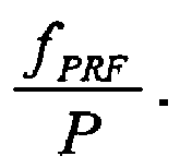
- The Doppler filter output is averaged over the frequency steps and the peak Doppler frequency is identified 24 by interpolating the averaged Doppler filter output in the

- Within the selected region the peak Doppler frequency is assumed to correspond to the skin return of the target and therefore the peak Doppler frequency can be used to determine the range rate correction.
- Step viii. corresponds to a single iteration of calculating a range rate correction and a corrected range rate estimate. The
method 40 may be extended to include one or more additional iterations, with the following steps: - a) adding the range rate correction to the estimate of the range rate to obtain a new range rate estimate;
- b) repeating steps iii. to vii. using the new range rate estimate and a) one or more times to produce a final range rate correction;
- c) adding the final range rate correction to the estimate of the range rate to obtain a final range rate estimate; and
- d) repeating steps iii. and iv. using the final range rate estimate to obtain motion compensated receiver samples.
- The range rate correction can therefore be iteratively determined to obtain a more accurate range rate estimate.
- The receiver samples form a discrete series and it will therefore be appreciated that discrete Fourier transforms and inverse discrete Fourier transforms are used.
-
Figures 3 and4 illustrate the improvement in an HRR profile which may be obtained by using themethod 40. In this example, a moving target is illuminated in both instances with a stepped-frequency pulse radar signal having a starting carrier frequency, fTx, of 2708.2MHz, a frequency step, Δf, of 3.2MHz, and a pulse repetition frequency, fPRF, of 2.5kHz. The pulse radar signal comprises 32 frequency steps, Q, each comprising 32 pulses, P, each pulse having a chirp bandwidth, B, of -4.5MHz and a duration, τ, of 25.6µs. -
Figure 3(a) shows theDoppler filter output 50 from step v., the receiver samples being processed by applying steps i. to v. and ix., i.e. the steps of themethod 40 without applying steps vi. to viii. to calculate a range rate correction. It can be seen that theskin return 52 is offset from 0Hz, which is where the skin return would be located if the target was not moving. JEM lines 54 are clearly visible above and below the skin return. -
Figure 3(b) shows aClassical HRR profile 56 obtained from the receiver samples obtained after the Doppler filtering step. As can be seen, the HRR profile is significantly degraded. The method of producing a Classical HRR profile will be well known to the person skilled in the art and so it will not be described in detail here. -
Figure 4(a) shows theDoppler filter output 60 from step v. following application of steps i. to viii. of themethod 40, that is to say, following correction of the range rate estimate. Theskin return 62 is clearly centred about 0Hz. JEM lines 64 are again visible above and below the skin return. -
Figure 4(b) shows aClassical HRR profile 66 generated from the output signal of step ix. of themethod 40. As can be seen, the HRR profile is much improved as compared to that shown inFigure 3(b) and themethod 40 has clearly compensated for bulk motion of the target. - The steps of a
method 70 of providing a radar range profile of a moving target according to third embodiment of the invention are shown inFigure 5 . Themethod 70 comprises many of the steps of the pulse radar range profilemotion compensation method 10 ofFigure 1 and the same reference numbers are retained for corresponding steps. - The
method 70 comprises the steps: - a. generating and transmitting a pulse radar signal to the
target 72, the pulse radar signal having a carrier frequency, fTx, and comprising a plurality, P, of pulses having a pulse repetition frequency, fPRF; - b. receiving corresponding radar echo signals from the target and sampling the echo signals to generate receiver samples corresponding to the
pulses 74; - c. acquiring an estimate of the range rate of the
target 14; - d. removing an additional phase acquired by the echo signals in dependence on the range rate and a time to a pulse since the start of the
look 16; - e. removing a shift in range cells of the receiver samples in dependence on the range rate and a time to a pulse since the start of the
look 18; - f. applying a pulse Doppler filter to the receiver samples from step e. 22;
- g. identifying the peak Doppler frequency corresponding to a skin return of the target and calculating a shift from zero, fD, of the
peak Doppler frequency 24; - h. calculating a range rate correction Δυ as

- i. adding the range rate correction to the estimate of the range rate to obtain a new range rate estimate and repeating steps d. and e. to obtain motion compensated
receiver samples 28; and - j. generating a high range resolution profile of the target from the motion compensated
receiver samples 76. - It will be appreciated that the
method 70 of this embodiment may alternatively comprise the steps of the pulse radar range profilemotion compensation method 40 ofFigure 2 . - The
method 70 of this embodiment is used to generate the HRR profile ofFigure 4(b) .
Claims (16)
- A pulse radar range profile motion compensation method comprising:i. acquiring receiver samples of radar echo signals generated by a target moving at a range rate, R, and illuminated during a look by a pulse radar signal having a carrier frequency, fTx, and comprising a plurality, P, of pulses having a pulse repetition frequency, fPRF;ii. acquiring an estimate of the range rate of the target;iii. removing an additional phase acquired by the echo signals in dependence on the range rate and a time to a pulse since the start of the look;iv. removing a shift in range cells of the receiver samples in dependence on the range rate and a time to a pulse since the start of the look;v. applying a pulse Doppler filter to the receiver samples from step iv.;vi. identifying the peak Doppler frequency corresponding to a skin return of the target and calculating a shift from zero, fD, of the peak Doppler frequency;vii. calculating a range rate correction Δυ as
 viii. adding the range rate correction to the estimate of the range rate to obtain a new range rate estimate and repeating steps iii. and iv. using the new range rate estimate to obtain motion compensated receiver samples; andix. generating an output signal indicative of the motion compensated receiver samples for generating a range profile.
 - A pulse radar range profile motion compensation method as claimed in claim 1, wherein the pulse radar signal comprises a frequency coded waveform and following step iv. the method further comprises applying a pulse compression to the receiver samples, identifying a range cell corresponding to a maximum power of the pulse compressed receiver samples and, for each pulse, selecting a receiver sample corresponding to the identified range cell.
- A pulse radar range profile motion compensation method as claimed in claim 1 or 2, wherein step iii. comprises applying a complex multiplication of

- A pulse radar range profile motion compensation method as claimed in any preceding claim, wherein step iv. comprises generating a Fourier transform of the receiver samples of step iii. and multiplying the Fourier transform by a phase ramp corresponding to the target range shift,

- A pulse radar range profile motion compensation method as claimed in any preceding claim, wherein in step v., the Doppler filter comprises outputs at Doppler frequencies in the range ― ½ fPRF to ½ fPRF and spaced by

- A pulse radar range profile motion compensation method as claimed in claim 5, wherein step v. comprises multiplying the receiver samples by a windowing function and generating a Fourier transform of the resulting receiver samples.
- A pulse radar range profile motion compensation method as claimed in claim 5, wherein the windowing function comprises a low sidelobe Dolph-Chebychev windowing function.
- A pulse radar range profile motion compensation method as claimed in any of claims 3 to 7, wherein the Fourier transform comprises a discrete Fourier transform.
- A pulse radar range profile motion compensation method as claimed in any preceding claim, wherein the range rate correction, Δυ, does not exceed

- A pulse radar range profile motion compensation method as claimed in any preceding claim, wherein the radar signal comprises a stepped-frequency waveform comprising a second plurality, Q, of frequency steps, each frequency step comprising a said plurality, P, of pulses.
- A pulse radar range profile motion compensation method as claimed in claim 10, wherein step iii. comprises applying a complex multiplication of

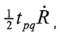
- A pulse radar range profile motion compensation method as claimed in claim 10 or 11, wherein step iv. comprises multiplying the Fourier transform by a phase ramp corresponding to the target range shift,
- A pulse radar range profile motion compensation method as claimed in any of claims 10 to 12 when dependent on claim 2, wherein the maximum power is identified across all pulses, all frequency steps and all receiver samples.
- A pulse radar range profile motion compensation method as claimed in any of claims 10 to 13, wherein step v. further comprises averaging the Doppler filter output over the frequency steps and step vi. comprises identifying the peak Doppler frequency by interpolating the averaged Doppler filter output in the region

- A pulse radar range profile motion compensation method as claimed in any preceding claim, wherein step viii. comprises:a) adding the range rate correction to the estimate of the range rate to obtain a new range rate estimate;b) repeating steps iii. to vii. using the new range rate estimate and a) one or more times to produce a final range rate correction;c) adding the final range rate correction to the estimate of the range rate to obtain a final range rate estimate; andd) repeating steps iii. and v. using the final range rate estimate to obtain motion compensated receiver samples.e) The range rate correction can therefore be iteratively determined to obtain a more accurate range rate estimate.
- A method of providing a radar range profile of a moving target, the method comprising:a. generating and transmitting a pulse radar signal to the target, the pulse radar signal having a carrier frequency, fTx, and comprising a plurality, P, of pulses having a pulse repetition frequency, fPRF;b. receiving corresponding radar echo signals from the target and sampling the echo signals to generate receiver samples corresponding to the pulses;c. acquiring an estimate of the range rate of the target;d. removing an additional phase acquired by the echo signals in dependence on the range rate and a time to a pulse since the start of the look;e. removing a shift in range cells of the receiver samples in dependence on the range rate and a time to a pulse since the start of the look;f. applying a pulse Doppler filter to the selected receiver samples from step e.;g. identifying the peak Doppler frequency corresponding to a skin return of the target and calculating a shift from zero, fD, of the peak Doppler frequency;h. calculating a range rate correction Δυ as
 i. adding the range rate correction to the estimate of the range rate to obtain a new range rate estimate and repeating steps d. and e. to obtain motion compensated receiver samples; andj. generating a high range resolution profile of the target from the motion compensated receiver samples.
Priority Applications (7)
| Application Number | Priority Date | Filing Date | Title |
|---|---|---|---|
| EP10250040A EP2343570A1 (en) | 2010-01-11 | 2010-01-11 | Pulse radar range profile motion compensation |
| PL10801256T PL2524239T3 (en) | 2010-01-11 | 2010-12-21 | Pulse radar range profile motion compensation |
| US13/521,371 US9170323B2 (en) | 2010-01-11 | 2010-12-21 | Pulse radar range profile motion compensation |
| PCT/GB2010/052172 WO2011083300A1 (en) | 2010-01-11 | 2010-12-21 | Pulse radar range profile motion compensation |
| AU2010340812A AU2010340812B2 (en) | 2010-01-11 | 2010-12-21 | Pulse radar range profile motion compensation |
| ES10801256.8T ES2689937T3 (en) | 2010-01-11 | 2010-12-21 | Motion compensation of a pulse radar distance profile |
| EP10801256.8A EP2524239B1 (en) | 2010-01-11 | 2010-12-21 | Pulse radar range profile motion compensation |
Applications Claiming Priority (1)
| Application Number | Priority Date | Filing Date | Title |
|---|---|---|---|
| EP10250040A EP2343570A1 (en) | 2010-01-11 | 2010-01-11 | Pulse radar range profile motion compensation |
Publications (1)
| Publication Number | Publication Date |
|---|---|
| EP2343570A1 true EP2343570A1 (en) | 2011-07-13 |
Family
ID=42224784
Family Applications (1)
| Application Number | Title | Priority Date | Filing Date |
|---|---|---|---|
| EP10250040A Ceased EP2343570A1 (en) | 2010-01-11 | 2010-01-11 | Pulse radar range profile motion compensation |
Country Status (1)
| Country | Link |
|---|---|
| EP (1) | EP2343570A1 (en) |
Cited By (9)
| Publication number | Priority date | Publication date | Assignee | Title |
|---|---|---|---|---|
| CN104375139A (en) * | 2014-09-29 | 2015-02-25 | 西安电子科技大学 | Pulse Doppler radar ranging improvement method based on one-dimensional set method |
| CN110031806A (en) * | 2018-01-11 | 2019-07-19 | 英飞凌科技股份有限公司 | The system and method for improving the range accuracy in fmcw radar using the chirp of FSK modulation |
| CN114019470A (en) * | 2021-11-03 | 2022-02-08 | 上海交通大学 | Method and system for target detection and parameter estimation |
| CN114660558A (en) * | 2022-03-26 | 2022-06-24 | 西安电子科技大学 | Improved keystone-based coherent accumulation method, system, equipment and storage medium for plasma sheath cladding target |
| CN115407279A (en) * | 2022-09-01 | 2022-11-29 | 中国人民解放军海军工程大学 | A Compensation Method for Range-Doppler Coupling Error in Pulse Compression Radar |
| KR102519748B1 (en) * | 2022-08-16 | 2023-04-10 | 국방과학연구소 | Signal integration apparatus and method for target detection |
| CN116299276A (en) * | 2023-02-28 | 2023-06-23 | 中国人民解放军国防科技大学 | A Method for Eliminating False Peaks in Target Range Image Based on Slice Modulation Design |
| CN117572426A (en) * | 2024-01-17 | 2024-02-20 | 长沙莫之比智能科技有限公司 | Vehicle-mounted millimeter wave radar static target detection method |
| WO2025095842A1 (en) * | 2023-10-31 | 2025-05-08 | Telefonaktiebolaget Lm Ericsson (Publ) | Radar detection with doppler-based delay correction |
Citations (4)
| Publication number | Priority date | Publication date | Assignee | Title |
|---|---|---|---|---|
| US5229775A (en) * | 1991-09-06 | 1993-07-20 | Mitsubishi Denki Kabushiki Kaisha | Digital pulse compression apparatus |
| US5309161A (en) * | 1992-12-10 | 1994-05-03 | General Electric Co. | Radar with doppler tolerant range sidelobe suppression and time domain signal processing |
| WO2000004401A1 (en) * | 1998-07-14 | 2000-01-27 | Raytheon Company | Noncoherent gain enhancement technique for improved detection-estimation performance |
| WO2005050240A2 (en) * | 2003-11-18 | 2005-06-02 | Elop Electro-Optics Industries Ltd. | Method and system for determining the range and velocity of a moving object |
-
2010
- 2010-01-11 EP EP10250040A patent/EP2343570A1/en not_active Ceased
Patent Citations (4)
| Publication number | Priority date | Publication date | Assignee | Title |
|---|---|---|---|---|
| US5229775A (en) * | 1991-09-06 | 1993-07-20 | Mitsubishi Denki Kabushiki Kaisha | Digital pulse compression apparatus |
| US5309161A (en) * | 1992-12-10 | 1994-05-03 | General Electric Co. | Radar with doppler tolerant range sidelobe suppression and time domain signal processing |
| WO2000004401A1 (en) * | 1998-07-14 | 2000-01-27 | Raytheon Company | Noncoherent gain enhancement technique for improved detection-estimation performance |
| WO2005050240A2 (en) * | 2003-11-18 | 2005-06-02 | Elop Electro-Optics Industries Ltd. | Method and system for determining the range and velocity of a moving object |
Cited By (12)
| Publication number | Priority date | Publication date | Assignee | Title |
|---|---|---|---|---|
| CN104375139A (en) * | 2014-09-29 | 2015-02-25 | 西安电子科技大学 | Pulse Doppler radar ranging improvement method based on one-dimensional set method |
| CN104375139B (en) * | 2014-09-29 | 2017-01-25 | 西安电子科技大学 | Pulse Doppler radar ranging improvement method based on one-dimensional set method |
| CN110031806A (en) * | 2018-01-11 | 2019-07-19 | 英飞凌科技股份有限公司 | The system and method for improving the range accuracy in fmcw radar using the chirp of FSK modulation |
| CN114019470A (en) * | 2021-11-03 | 2022-02-08 | 上海交通大学 | Method and system for target detection and parameter estimation |
| CN114660558A (en) * | 2022-03-26 | 2022-06-24 | 西安电子科技大学 | Improved keystone-based coherent accumulation method, system, equipment and storage medium for plasma sheath cladding target |
| KR102519748B1 (en) * | 2022-08-16 | 2023-04-10 | 국방과학연구소 | Signal integration apparatus and method for target detection |
| CN115407279A (en) * | 2022-09-01 | 2022-11-29 | 中国人民解放军海军工程大学 | A Compensation Method for Range-Doppler Coupling Error in Pulse Compression Radar |
| CN115407279B (en) * | 2022-09-01 | 2024-04-19 | 中国人民解放军海军工程大学 | A method for compensating range-Doppler coupling errors in pulse compression radar |
| CN116299276A (en) * | 2023-02-28 | 2023-06-23 | 中国人民解放军国防科技大学 | A Method for Eliminating False Peaks in Target Range Image Based on Slice Modulation Design |
| WO2025095842A1 (en) * | 2023-10-31 | 2025-05-08 | Telefonaktiebolaget Lm Ericsson (Publ) | Radar detection with doppler-based delay correction |
| CN117572426A (en) * | 2024-01-17 | 2024-02-20 | 长沙莫之比智能科技有限公司 | Vehicle-mounted millimeter wave radar static target detection method |
| CN117572426B (en) * | 2024-01-17 | 2024-05-10 | 长沙莫之比智能科技有限公司 | Vehicle-mounted millimeter wave radar static target detection method |
Similar Documents
| Publication | Publication Date | Title |
|---|---|---|
| EP2524239B1 (en) | Pulse radar range profile motion compensation | |
| CN102590812B (en) | SAR (synthetic aperture radar) real-time imaging method based on frequency modulated continuous wave | |
| US10754008B2 (en) | Vehicle radar system that addresses doppler frequency shift and method of using the same | |
| CN107076834B (en) | Radar operation with increased Doppler capability | |
| US20150084805A1 (en) | Detection Techniques | |
| USH1720H (en) | Time frequency processor for radar imaging of moving targets | |
| EP1718988B1 (en) | Rf channel calibration for non-linear fm waveforms | |
| EP3460513A1 (en) | Radar altimeter sea state estimation | |
| EP3479140B1 (en) | High range resolution radar profiling using frequency jump burst-pulse-doppler waveform and processing | |
| EP2677343A1 (en) | Passive radar device | |
| EP3771921B1 (en) | Method for processing non-interrupted phase synchronization signal of bistatic sar based on coded signal | |
| US8760340B2 (en) | Processing radar return signals to detect targets | |
| EP4258010B1 (en) | Automotive radar with range migration mitigation capability | |
| Ding et al. | A novel range grating lobe suppression method based on the stepped-frequency SAR image | |
| US12524033B2 (en) | Methods for designing high freedom parameterized frequency-modulated coded waveform | |
| EP3470874A1 (en) | Radar method and system for determining the angular position, the position and/or the speed of a target, in particular the vectorial speed | |
| US20120287964A1 (en) | Method of providing a radar high range resolution profile | |
| US8358233B2 (en) | Radar target detection process | |
| Wasserzier et al. | On the efficient computation of range and Doppler data in noise radar | |
| EP2343571A1 (en) | Method of providing a radar high range resolution profile | |
| EP4261564A1 (en) | Unambiguous and accurate velocity estimation by frequency-modulated radars | |
| US10386471B1 (en) | Velocity estimation with linear frequency modulated (LFM) waveforms | |
| CN110907930B (en) | Vehicle-mounted radar target detection and estimation method and device based on angle estimation | |
| CN115586507B (en) | A MIMO radar waveform design method to suppress velocity ambiguity | |
| Nguyen et al. | Comparing non-adaptive with adaptive windowing using multi-dimensional spatially variant apodization for automotive radar |
Legal Events
| Date | Code | Title | Description |
|---|---|---|---|
| PUAI | Public reference made under article 153(3) epc to a published international application that has entered the european phase |
Free format text: ORIGINAL CODE: 0009012 |
|
| AK | Designated contracting states |
Kind code of ref document: A1 Designated state(s): AT BE BG CH CY CZ DE DK EE ES FI FR GB GR HR HU IE IS IT LI LT LU LV MC MK MT NL NO PL PT RO SE SI SK SM TR |
|
| AX | Request for extension of the european patent |
Extension state: AL BA RS |
|
| STAA | Information on the status of an ep patent application or granted ep patent |
Free format text: STATUS: THE APPLICATION HAS BEEN REFUSED |
|
| 18R | Application refused |
Effective date: 20110801 |