EP2343538A2 - Electrical network analysis of a multiphase system - Google Patents
Electrical network analysis of a multiphase system Download PDFInfo
- Publication number
- EP2343538A2 EP2343538A2 EP10196465A EP10196465A EP2343538A2 EP 2343538 A2 EP2343538 A2 EP 2343538A2 EP 10196465 A EP10196465 A EP 10196465A EP 10196465 A EP10196465 A EP 10196465A EP 2343538 A2 EP2343538 A2 EP 2343538A2
- Authority
- EP
- European Patent Office
- Prior art keywords
- matrix
- material object
- electric element
- transformed
- determining
- Prior art date
- Legal status (The legal status is an assumption and is not a legal conclusion. Google has not performed a legal analysis and makes no representation as to the accuracy of the status listed.)
- Granted
Links
- 238000003012 network analysis Methods 0.000 title 1
- 239000011159 matrix material Substances 0.000 claims abstract description 161
- 239000000463 material Substances 0.000 claims abstract description 144
- 238000000034 method Methods 0.000 claims abstract description 64
- 230000009466 transformation Effects 0.000 claims abstract description 36
- 238000009826 distribution Methods 0.000 claims description 46
- 238000005259 measurement Methods 0.000 claims description 15
- 238000012545 processing Methods 0.000 claims description 10
- 239000000203 mixture Substances 0.000 claims description 7
- 230000000007 visual effect Effects 0.000 claims description 7
- 238000004088 simulation Methods 0.000 claims description 3
- 239000012071 phase Substances 0.000 description 28
- 238000002593 electrical impedance tomography Methods 0.000 description 9
- 238000004519 manufacturing process Methods 0.000 description 8
- XLYOFNOQVPJJNP-UHFFFAOYSA-N water Substances O XLYOFNOQVPJJNP-UHFFFAOYSA-N 0.000 description 7
- 238000004458 analytical method Methods 0.000 description 6
- 230000008569 process Effects 0.000 description 6
- 230000008901 benefit Effects 0.000 description 3
- 238000006243 chemical reaction Methods 0.000 description 3
- 238000010586 diagram Methods 0.000 description 3
- 239000012530 fluid Substances 0.000 description 3
- 238000012360 testing method Methods 0.000 description 3
- 239000007788 liquid Substances 0.000 description 2
- 239000007791 liquid phase Substances 0.000 description 2
- 238000012986 modification Methods 0.000 description 2
- 230000004048 modification Effects 0.000 description 2
- 239000003129 oil well Substances 0.000 description 2
- 206010028980 Neoplasm Diseases 0.000 description 1
- 201000011510 cancer Diseases 0.000 description 1
- 238000001311 chemical methods and process Methods 0.000 description 1
- 239000011248 coating agent Substances 0.000 description 1
- 238000000576 coating method Methods 0.000 description 1
- 230000003750 conditioning effect Effects 0.000 description 1
- 238000013461 design Methods 0.000 description 1
- 238000003745 diagnosis Methods 0.000 description 1
- 230000000694 effects Effects 0.000 description 1
- 230000005684 electric field Effects 0.000 description 1
- 239000000839 emulsion Substances 0.000 description 1
- 230000005484 gravity Effects 0.000 description 1
- 229930195733 hydrocarbon Natural products 0.000 description 1
- 150000002430 hydrocarbons Chemical class 0.000 description 1
- 230000033001 locomotion Effects 0.000 description 1
- 238000000691 measurement method Methods 0.000 description 1
- 238000012544 monitoring process Methods 0.000 description 1
- 238000009828 non-uniform distribution Methods 0.000 description 1
- 230000003534 oscillatory effect Effects 0.000 description 1
- 239000003208 petroleum Substances 0.000 description 1
- 230000003134 recirculating effect Effects 0.000 description 1
- 230000009467 reduction Effects 0.000 description 1
- 238000013341 scale-up Methods 0.000 description 1
- 239000000126 substance Substances 0.000 description 1
Images




Classifications
-
- G—PHYSICS
- G01—MEASURING; TESTING
- G01N—INVESTIGATING OR ANALYSING MATERIALS BY DETERMINING THEIR CHEMICAL OR PHYSICAL PROPERTIES
- G01N27/00—Investigating or analysing materials by the use of electric, electrochemical, or magnetic means
- G01N27/02—Investigating or analysing materials by the use of electric, electrochemical, or magnetic means by investigating impedance
-
- G—PHYSICS
- G01—MEASURING; TESTING
- G01N—INVESTIGATING OR ANALYSING MATERIALS BY DETERMINING THEIR CHEMICAL OR PHYSICAL PROPERTIES
- G01N33/00—Investigating or analysing materials by specific methods not covered by groups G01N1/00 - G01N31/00
- G01N33/26—Oils; Viscous liquids; Paints; Inks
- G01N33/28—Oils, i.e. hydrocarbon liquids
- G01N33/2823—Raw oil, drilling fluid or polyphasic mixtures
Definitions
- This invention relates generally to a method for determining the composition and characteristics of the individual materials within a multi-material object, and, more specifically, to a method of analyzing the electrical network representation of the multi-material object.
- Multiphase flow is an example of a multi-material object in which at least two materials or phases are flowing together inside a pipe or a conduit.
- Multiphase flow processes are important to a variety of industries including, for example, petroleum, pharmaceutical, food, and chemical industries. There is a need for direct knowledge of the internal flow characteristics in these types of multiphase flow processes to enable improved design and increased operational efficiency of existing and new processing equipment.
- Characteristics used to predict performance of multiphase processes may include, for example, spatial distribution of the phases (spatial volumetric phase fractions), flow regime, interfacial area, and absolute and relative velocities between the phases or materials.
- Knowing the spatial distribution of the materials is particularly useful because non-uniform distribution of the materials tends to reduce the interfacial area between materials available for chemical reaction or conversion and may result in recirculating flows creating spatially non-uniform reaction zones or concentrations. Further, the volumetric phase fraction and velocity are important parameters that enable proper and timely control of multiphase flows.
- EIT Electrical-impedance tomography
- a map of the electrical conductivity and permittivity is used to infer the distribution of different materials within a multi-material object.
- Different current patterns or voltage patterns are applied to the object through electrodes surrounding the object, and the corresponding voltages or currents are measured. Based on the current-voltage relations, an internal impedance or internal admittance distribution is determined.
- Image reconstruction based on the calculated impedance distribution using various image processing algorithms is one method by which distribution of different materials within the multi-material object is determined.
- image-processing algorithms are often too time-consuming and computationally intensive. They also ignore many qualitative aspects of the problem such as spatial symmetry or asymmetry.
- a method for determining characteristics of a multi-material object includes determining an electric element matrix representing the multi-material object and pre-multiplying the electric element matrix with a first mathematical transformation matrix to obtain a first transformed electric element matrix.
- the method also includes post-multiplying the first transformed electric element matrix with a second mathematical transformation matrix to obtain a second transformed electric element matrix.
- the method further includes determining the characteristics of the multi-material object based on the second transformed electric element matrix.
- a multi-material sensing system includes a power supply for providing an applied electrical signal set to electrodes surrounding a multi-material object and a measurement unit for obtaining a measured electrical signal set from the electrodes.
- the system further includes a processing circuitry for determining an electric element matrix based on the applied and the measured signal sets and for pre-multiplying the electric element matrix with a first mathematical transformation matrix to obtain a first transformed electric element matrix.
- the processing circuitry further post-multiplies the first transformed electric element matrix with a second mathematical transformation matrix to obtain a second transformed electric element matrix and determines the characteristics of the multi-material object based on the second transformed electric element matrix.
- a method for determining characteristics of a multi-material object includes providing an applied electrical signal set to the electrodes surrounding the multi-material object and obtaining a measured electrical signal set of measured electrical signals from the electrodes. The method further includes pre-multiplying the measured electrical signal set with a first mathematical transformation matrix to obtain a first transformed measured electrical signal set and post-multiplying the first transformed measured electrical signal set with a second mathematical transformation matrix to obtain a second transformed measured electrical signal set. The method also includes determining the characteristics of the multi-material object based on the second transformed measured electrical signal set.
- FIG. 1 is a block diagram of a oil production facility according to an example embodiment
- FIG. 2 is a schematic of an electrical impedance tomography (EIT) based multiphase flow meter to be used in accordance with an embodiment of the present invention
- FIG. 3 is a block diagram of an applied-voltage EIT system in accordance with an embodiment of the present invention.
- FIG. 4 is representation of three different flow regimes of a mixture of two phase components
- FIG. 5 is a graphical representation of the variation of a matrix element Y (2,2) with a fraction of a secondary phase
- FIG. 6 is a graphical representation of the variation of a matrix element Y (2,3) with mean distance of the secondary phase from central axis of conduit;
- FIG. 7 is a graphical representation of the an original distribution and its equivalent distribution of the secondary phase in accordance with an embodiment of the present invention.
- FIG. 8 is a flow chart representing a method of determining characteristics of a multi-material object in accordance with an embodiment of the present invention.
- FIG. 9 is a flow chart representing an analysis of a multi-material object in accordance with an embodiment of the present invention.
- FIG. 10 is a flow chart representing a method of determining characteristics of a multi-material object based on an electrical signal set in accordance with an embodiment of the present invention.
- embodiments of the present invention function to provide a system and a method for measuring the characteristics of a multi-material object.
- the characteristics of the object may include volumetric fractions and flow rates of oil, water, and gas (in this context referencing gaseous hydrocarbons) flowing through conduits.
- oil/gas/water measurements it is by no means limited to such applications; rather, aspects of the invention find application in a wide variety of industrial, healthcare and chemical processes such as, cancer diagnosis and water treatment processes.
- the characteristics of such multi-material objects may be quite different from the examples given for multiphase flow.
- FIG. 1 shows an oil production facility 10 according to an example embodiment.
- the oil production facility typically includes multiple oil wells 12 that are each interconnected to a piping system 14.
- the piping system 14 includes a production manifold 16 coupled to multiphase flow meters (MPFMs) 18.
- MPFMs multiphase flow meters
- a multiphase flow meter enables measurement of unprocessed well streams very close to the well and thus can provide continuous monitoring of well performance, which may be used for better reservoir management.
- Fluids pumped from oil wells 12 are sent to a production separator 20 through the production manifold 16.
- a test separator (not shown) may additionally be used along with MPFMs in the facility 10 or may alternatively be used.
- One advantage of a MPFM over a test separator is the reduction in time needed to perform a measurement. While the test separator must be allowed to fill and stabilize when changing wells, the MPFM responds more quickly to changes in well fluids and needs less time to stabilize.
- the production separator 20 separates oil, gas, and water pumped from the wells.
- the production separator 20 may include one or more measurement devices.
- the measurement devices may include, for example, a water meter to measure an amount or rate of water extracted from a well and an emulsion meter to measure an amount of oil extracted from the well. Further measurement devices may include other devices typically utilized to monitor well performance such as a wellhead pressure sensor, thermometer, salinity meter and a pH meter.
- FIG. 2 shows an electrical impedance tomography (EIT) based MPFM system 40.
- EIT electrical impedance tomography
- the conductivity or permittivity distribution within a multi-material object is inferred from electrical measurements made through electrodes surrounding the object.
- Conducting electrodes are attached to the periphery of the multi-material object and alternating currents or voltages are applied to some or all of the electrodes. The resulting electrical potentials or currents respectively are measured, and the process is repeated for numerous different configurations or patterns of applied currents and/or voltages.
- the MPFM system 40 of FIG. 2 includes an electrode array 42 comprising a number of electrodes 44 distributed around a conduit 46.
- the conduit may comprise a container, which carries multiple materials or phases within it, such as a pipe or tank, or the conduit may comprise another vessel such as a part of a human body or an entire human body.
- the number of electrodes may be eight, twelve or sixteen, depending on the size of the conduit and the accuracy needed.
- the electrodes may be attached directly to the inside wall of the conduit with one embodiment including use of a suitable coating to ensure good electrical contact, if needed.
- the electrodes are connected to electronic conditioning circuitry 48, which may include components such as a current or voltage source, D-to-A-converters, A-to-D converters, differential amplifiers, filters, digital multiplexers, analog multiplexers, a clock, and/or a digital I/O unit coupled to a computer 50.
- Computer 50 comprises, in one embodiment, a personal computer equipped with a digital signal processor card used for the image reconstruction process and a suitable display 52 for displaying the images.
- Other processing circuits such as a field-programmable gate array (FPGA) or a complex programmable logic device (CPLD) may also be used in other embodiments.
- FPGA field-programmable gate array
- CPLD complex programmable logic device
- electrodes 44 are stimulated by applying a voltage set of voltage patterns across them, which produces rotating electric field within the multi-material object in the conduit.
- one or more voltage sources are used to apply one pattern of voltages to the electrodes, and the corresponding set of current signals in each of the electrodes is measured.
- one or more current sources are used to stimulate the electrodes by injecting currents into them, and corresponding voltages are measured across the electrodes.
- FIG. 3 is a block diagram 60 of an applied-voltage EIT system with L electrodes.
- Each electrode 61 is connected to a circuit that includes a voltage source 62 for generating the applied voltage as well as an ammeter to measure the applied current and a voltmeter to directly measure the applied voltage.
- a switching network 63 enables a single calibration circuit 64 to be connected to any of the voltage source/ammeter/voltmeter circuits to allow the whole system to be calibrated to a single reference.
- a digital controller (not shown) may be interfaced to the voltage sources (with ammeters and voltmeters), switches, and the calibration circuit may be used to set the system configurations and collect digital measurements of voltage and current.
- the currents are generated using current sources, which may comprise direct current sources or a system of voltage-to-current converters, for example.
- the resulting measurements are processed by the computer 50 ( FIG. 2 ), and the representation of the electrical impedance or admittance distribution within the multi-material object is determined.
- the electrical impedance or admittance distribution is then further analyzed by the computer 50 to provide characteristics of the multi-material object. Characteristics of the multi-material object may include, for example, composition and distribution of materials of the system. Further, the electrical impedance or admittance distribution may also be analyzed to determine flow regimes, phase fraction, and velocity of individual materials of the multi-material object.
- the flow regimes may include but are not limited to bubbly flow, chum flow, slug flow, or annular flow, for example.
- the current flowing from one electrode to another is a function of relative voltages applied across all electrodes and the conductivity and permittivity of the materials present between all the electrodes.
- the material may be only oil or it may be a mixture of oil and gas.
- the impedance or admittance between all the electrodes varies, and the current flowing between electrodes also varies.
- the impedance set or impedance matrix of impedances between every pair of electrodes can be calculated.
- the admittance set or admittance matrix of impedances between every pair of electrodes can alternatively or additionally be calculated.
- impedance and admittance are a function of the conductivity and the permittivity of the materials between electrodes
- the material distribution and its characteristics may be determined.
- Several methods can be employed to compute the impedance or admittance matrix from the applied electrical signal set and the measured electrical signal set. These methods may include but are not limited to using a pseudo-inverse or an iterative algorithm.
- the measured electrical signals may comprise voltage signals or current signals. It should be noted that since the measured electrical signals are also a function of conductivity and the permittivity of the materials between electrodes, in one embodiment, it is possible to analyze the characteristics of the multi-material object by analyzing the measured electrical signal set of measured electrical signals.
- the analysis of an admittance network includes pre-multiplying the impedance or the admittance matrix Y with a first mathematical transformation matrix A and post-multiplying the resultant product matrix by a second mathematical transformation matrix B as given by equation (1).
- the matrix Y and Y may have an L number of rows and an L number of columns, where L is the number of electrodes.
- the matrices A and B may or may not be related to each other. Further, the matrices A and B would have appropriate number of rows and columns so that the multiplications as shown in equation (1) may be achieved. It will be appreciated by those skilled in the art that pre-multiplication refers to multiplication on left and post-multiplication refers to multiplication on right as shown in equation (1).
- the multiplication of matrix Y with A and B may transform the coordinate system or convert the impedance or admittance matrix into a spatial Fourier transform domain.
- the matrices A and B given in equation (1) may by themselves be the product of several matrices.
- the matrix A or B may be an identity matrix.
- the matrices A and B in equation (1) may be the L-point Discrete Fourier Transform (DFT) matrix and its inverse respectively.
- DFT Discrete Fourier Transform
- the energized electrodes refer to the electrodes to which voltage signals or current signals are applied. In one embodiment there may be 8 electrodes out of which only 4 electrodes are energized.
- the various elements of the transformed matrix Y contain useful information on the characteristics of the multi-material object.
- the diagonals of the transformed impedance matrix represent the spatial symmetry in the distribution of the materials within the multi-material object and the off-diagonal elements represent the asymmetry in the distribution of materials within the multi-material object.
- All the elements in the first column and the first row of the matrix Y typically have a value of zero except in the case where there may be an alternate path for the passage of electric current apart from the electrodes used. Therefore, the elements in the first row and first column of Y can be used as indicators for the presence of leakage currents and alternate paths for such currents or the existence of ground faults in the EIT system. It should be noted that in one embodiment, Y may contain time varying elements.
- the matrix Y is analyzed continuously in real time, it will have no effect in determining the characteristics of the multi-material object.
- the measured electrical signal set is mathematically transformed and based on elements of the transformed measured electrical signal set the characteristics of the multi-material object are determined.
- equation (2) the only difference in this embodiment is that in equation (2), the matrix Y will be replaced by the measured electrical signal set i.e. voltage matrix or current matrix.
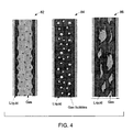
- FIG. 4 shows three different regimes as a mixture of two materials flows through a conduit.
- the two phases in the example of FIG. 4 include a gas and a liquid.
- Flow regime 82 is an annular flow regime where the gas phase tends to move through the center of the conduit and the liquid phase forms an annulus around the gas phase.
- Flow regime 84 for example, is a bubbly flow and is characterized by the gas phase being distributed as bubbles through the liquid phase.
- Flow regime 86 is a representation of chum flow and is characterized by oscillatory, up and down motions of the liquid.
- the different elements of the matrix Y can be used to identify various flow regimes.
- the flow can be said to be spatially symmetric when a single homogenous material flows through the conduit.
- all the elements have a value of zero.
- the element in the first row and first column may also be zero.
- a, b and c in equation (5) would scale up or down linearly depending upon the electrical properties of the homogenous material flowing through the conduit.
- the values of a, b and c in equation (5) may be used to determine the electrical properties of the homogenous material within the conduit.
- Y ⁇ bubbly 0 0 0 0 0 a ⁇ f m 0 x b ⁇ n 0 y g c ⁇
- the elements along the diagonal in equation (7), a " , b " and c" are different from the case where a single homogenous material flows through the conduit.
- the absolute and relative values of the diagonal and non-diagonal elements can be used to identify the flow regime.
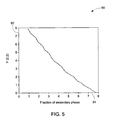
- FIG. 5 shows a plot 90 of variation of the element at the second row and second column of the matrix Y , called Y (2,2), with increasing fraction of the secondary phase or material.
- the horizontal axis 91 represents the phase fraction of secondary phase and the vertical axis 92 represents values of element (2,2) of the matrix Y .
- FIG. 6 shows a plot 94 of variation of the element at the second row and third column in matrix Y , called Y (2,3) with increasing mean distance of the fraction of the secondary phase or material from the central axis of the conduit.
- the horizontal axis 95 represents the mean distance of the secondary phase from the central axis of the conduit and the vertical axis 96 represents the values of element (2,3) of the matrix Y .
- the data shown in FIG. 5 and FIG. 6 may be obtained by several numerical simulations of randomly generated flow regimes and material distributions within the conduit that may be corrected based on experimental results.
- the values of other elements within the Y matrix for different flow regimes and material distributions may be numerically calculated and/or empirically corrected. It should be noted that the other elements may have non-linear relations to the original distribution unlike the linear relationships shown in the graphs in FIG. 5 and FIG. 6 .
- FIG. 7 shows an original distribution 97 and its equivalent distribution 98 of the secondary phase visualized from the behavior of the various elements of the Y matrix in accordance with an embodiment of the present invention.
- the original distribution 97 shown for example is a bubbly flow distribution. From the current and voltage measurements made on electrodes placed around the conduit carrying this bubbly distribution, a Y matrix and subsequently a Y matrix may be computed.
- the element Y (2,2) represents the total fraction occupied by the secondary phase in the plane of the electrodes and Y (2,3) represents the mean distance of the secondary phase from the central axis of the conduit. From these two elements of the Y matrix, it is possible to equivalently represent the material distribution within the conduit as shown in the equivalent distribution 98.
- the equivalent distribution 98 various distributed areas 99 of the secondary phase are combined into a single area 100 and the mean distance of the single area of the secondary phase from the central axis of the conduit is shown by a variable R. It should be noted that the equivalent representation of the materials within the conduit is different from the result a full image processing or reconstruction algorithm would produce using the current and voltage information.
- the advantage of the equivalent distribution 98 is that while being a visual method of representing the original material distribution within the conduit, it does not increase the computation needed significantly.
- the elements of the Y matrix from one or more sets of electrodes provide an indication of the velocity and density of various phases or materials within the conduit.
- These models may be coupled with numerical fluid dynamics models and electromagnetic models of multiphase flow in order to predict and correct the measurements in real-time.
- FIG. 8 is a flow chart 101 for a method of determining the characteristics of a multi-material object in accordance with one embodiment of the present invention.
- the method includes determining the electric element matrix representing the multi-material object in step 102. This can be achieved by a number of methods and may involve using the pseudo-inverse of an applied or measured electrical signal set, for example.
- the electric element matrix is pre-multiplied by a predefined first mathematical transformation matrix A to compute a first transformed electric element matrix.
- the first transformed electric element matrix is post-multiplied by a predefined second mathematical transformation matrix B to compute a second transformed electric element matrix.
- the characteristics of the multi-material object are determined from the analysis of the second transformed electric element matrix.
- the electric element matrix could be an impedance matrix or an admittance matrix representing the multi-material object, for example.
- FIG. 9 is a flow chart 110 for an analysis of a multi-material object that can be performed in accordance with one embodiment of the present invention.
- the method includes determining electric element matrix representing the multi-material object in step 112.
- the electric element matrix is pre-multiplied by a predefined first mathematical transformation matrix A to compute a first transformed electric element matrix.
- the first transformed electric element matrix is post-multiplied by a predefined second mathematical transformation matrix B to compute a second transformed electric element matrix.
- the characteristics of the multi-material object are determined from the analysis of the second transformed electric element matrix.
- an equivalent visual representation of the material distribution within the multi-material object is determined and displayed.
- One example of the equivalent visual representation is shown in FIG. 7 .
- FIG. 10 is a flow chart 130 for a method of determining the characteristics of a multi-material object based on an electrical signal set in accordance with an embodiment of the present invention. Since the electric element matrix can be determined from applied electrical signals and measured electrical signals, in one embodiment, it is possible to directly determine the characteristics of a multi-material object from the applied electrical signal set and the measured electrical signal set.
- the method includes providing an applied electrical signal set to the electrodes surrounding the multi-material object in step 132. In step 134, a measured electrical signal set of measured electrical signals from the electrodes is obtained.
- a current matrix I of measured current signals or a voltage matrix V of measured voltage signals from the electrodes is used directly (instead of having the intermediate step of forming the electric element matrix) to determine characteristics of the multi-material object.
- the currents are measured when voltages are applied to electrodes and voltages are measured when currents are applied to the electrodes.
- the measured electrical signal set is pre-multiplied by a predefined first mathematical transformation matrix A' to compute a first transformed measured electrical signal set.
- the first transformed second electrical signal set is post-multiplied by a predefined second mathematical transformation matrix B' to compute a second transformed measured electrical signal set.
- the matrices A' and B' will have different values compared to A and B of method described in FIG. 8 .
- the characteristics of the multi-material object are determined from the analysis of the second transformed measured electrical signal set.
Landscapes
- Chemical & Material Sciences (AREA)
- Health & Medical Sciences (AREA)
- Life Sciences & Earth Sciences (AREA)
- General Health & Medical Sciences (AREA)
- Engineering & Computer Science (AREA)
- Chemical Kinetics & Catalysis (AREA)
- Pathology (AREA)
- Immunology (AREA)
- General Physics & Mathematics (AREA)
- Physics & Mathematics (AREA)
- Analytical Chemistry (AREA)
- Biochemistry (AREA)
- Oil, Petroleum & Natural Gas (AREA)
- Medicinal Chemistry (AREA)
- Food Science & Technology (AREA)
- General Chemical & Material Sciences (AREA)
- Electrochemistry (AREA)
- Investigating Or Analyzing Materials By The Use Of Electric Means (AREA)
- Measurement Of Resistance Or Impedance (AREA)
Abstract
Description
- This invention relates generally to a method for determining the composition and characteristics of the individual materials within a multi-material object, and, more specifically, to a method of analyzing the electrical network representation of the multi-material object.
- Multiphase flow is an example of a multi-material object in which at least two materials or phases are flowing together inside a pipe or a conduit. Multiphase flow processes are important to a variety of industries including, for example, petroleum, pharmaceutical, food, and chemical industries. There is a need for direct knowledge of the internal flow characteristics in these types of multiphase flow processes to enable improved design and increased operational efficiency of existing and new processing equipment. Characteristics used to predict performance of multiphase processes may include, for example, spatial distribution of the phases (spatial volumetric phase fractions), flow regime, interfacial area, and absolute and relative velocities between the phases or materials. Knowing the spatial distribution of the materials is particularly useful because non-uniform distribution of the materials tends to reduce the interfacial area between materials available for chemical reaction or conversion and may result in recirculating flows creating spatially non-uniform reaction zones or concentrations. Further, the volumetric phase fraction and velocity are important parameters that enable proper and timely control of multiphase flows.
- Electrical-impedance tomography (EIT) is a minimally invasive measurement technique that can be used to quantitatively map material distributions within multi-material objects. In EIT, a map of the electrical conductivity and permittivity is used to infer the distribution of different materials within a multi-material object. Different current patterns or voltage patterns are applied to the object through electrodes surrounding the object, and the corresponding voltages or currents are measured. Based on the current-voltage relations, an internal impedance or internal admittance distribution is determined.
- Image reconstruction based on the calculated impedance distribution using various image processing algorithms is one method by which distribution of different materials within the multi-material object is determined. However, image-processing algorithms are often too time-consuming and computationally intensive. They also ignore many qualitative aspects of the problem such as spatial symmetry or asymmetry.
- Therefore, it is desirable to determine a method and a system that will address the foregoing issues.
- In accordance with an embodiment of the present invention, a method for determining characteristics of a multi-material object is provided. The method includes determining an electric element matrix representing the multi-material object and pre-multiplying the electric element matrix with a first mathematical transformation matrix to obtain a first transformed electric element matrix. The method also includes post-multiplying the first transformed electric element matrix with a second mathematical transformation matrix to obtain a second transformed electric element matrix. The method further includes determining the characteristics of the multi-material object based on the second transformed electric element matrix.
- In accordance with another embodiment of the present invention a multi-material sensing system is provided. The system includes a power supply for providing an applied electrical signal set to electrodes surrounding a multi-material object and a measurement unit for obtaining a measured electrical signal set from the electrodes. The system further includes a processing circuitry for determining an electric element matrix based on the applied and the measured signal sets and for pre-multiplying the electric element matrix with a first mathematical transformation matrix to obtain a first transformed electric element matrix. The processing circuitry further post-multiplies the first transformed electric element matrix with a second mathematical transformation matrix to obtain a second transformed electric element matrix and determines the characteristics of the multi-material object based on the second transformed electric element matrix.
- In accordance with yet another embodiment of the present invention, a method for determining characteristics of a multi-material object is provided. The method includes providing an applied electrical signal set to the electrodes surrounding the multi-material object and obtaining a measured electrical signal set of measured electrical signals from the electrodes. The method further includes pre-multiplying the measured electrical signal set with a first mathematical transformation matrix to obtain a first transformed measured electrical signal set and post-multiplying the first transformed measured electrical signal set with a second mathematical transformation matrix to obtain a second transformed measured electrical signal set. The method also includes determining the characteristics of the multi-material object based on the second transformed measured electrical signal set.
- These and other features, aspects, and advantages of the present invention will become better understood when the following detailed description is read with reference to the accompanying drawings in which like characters represent like parts throughout the drawings, wherein:
-
FIG. 1 is a block diagram of a oil production facility according to an example embodiment; -
FIG. 2 is a schematic of an electrical impedance tomography (EIT) based multiphase flow meter to be used in accordance with an embodiment of the present invention; -
FIG. 3 is a block diagram of an applied-voltage EIT system in accordance with an embodiment of the present invention; -
FIG. 4 is representation of three different flow regimes of a mixture of two phase components; -
FIG. 5 is a graphical representation of the variation of a matrix elementY (2,2) with a fraction of a secondary phase; -
FIG. 6 is a graphical representation of the variation of a matrix elementY (2,3) with mean distance of the secondary phase from central axis of conduit; -
FIG. 7 is a graphical representation of the an original distribution and its equivalent distribution of the secondary phase in accordance with an embodiment of the present invention; -
FIG. 8 is a flow chart representing a method of determining characteristics of a multi-material object in accordance with an embodiment of the present invention; and -
FIG. 9 is a flow chart representing an analysis of a multi-material object in accordance with an embodiment of the present invention; and -
FIG. 10 is a flow chart representing a method of determining characteristics of a multi-material object based on an electrical signal set in accordance with an embodiment of the present invention. - As discussed in detail below, embodiments of the present invention function to provide a system and a method for measuring the characteristics of a multi-material object. In an example of a multiphase flow, the characteristics of the object may include volumetric fractions and flow rates of oil, water, and gas (in this context referencing gaseous hydrocarbons) flowing through conduits. Although the invention is described with reference to a use in oil/gas/water measurements, it is by no means limited to such applications; rather, aspects of the invention find application in a wide variety of industrial, healthcare and chemical processes such as, cancer diagnosis and water treatment processes. The characteristics of such multi-material objects may be quite different from the examples given for multiphase flow.
-
FIG. 1 shows anoil production facility 10 according to an example embodiment. The oil production facility typically includesmultiple oil wells 12 that are each interconnected to apiping system 14. Thepiping system 14 includes aproduction manifold 16 coupled to multiphase flow meters (MPFMs) 18. A multiphase flow meter enables measurement of unprocessed well streams very close to the well and thus can provide continuous monitoring of well performance, which may be used for better reservoir management. Fluids pumped fromoil wells 12 are sent to aproduction separator 20 through theproduction manifold 16. It should be noted that a test separator (not shown) may additionally be used along with MPFMs in thefacility 10 or may alternatively be used. One advantage of a MPFM over a test separator is the reduction in time needed to perform a measurement. While the test separator must be allowed to fill and stabilize when changing wells, the MPFM responds more quickly to changes in well fluids and needs less time to stabilize. - The
production separator 20 separates oil, gas, and water pumped from the wells. Theproduction separator 20 may include one or more measurement devices. The measurement devices may include, for example, a water meter to measure an amount or rate of water extracted from a well and an emulsion meter to measure an amount of oil extracted from the well. Further measurement devices may include other devices typically utilized to monitor well performance such as a wellhead pressure sensor, thermometer, salinity meter and a pH meter. -
FIG. 2 shows an electrical impedance tomography (EIT) basedMPFM system 40. In EIT, the conductivity or permittivity distribution within a multi-material object is inferred from electrical measurements made through electrodes surrounding the object. Conducting electrodes are attached to the periphery of the multi-material object and alternating currents or voltages are applied to some or all of the electrodes. The resulting electrical potentials or currents respectively are measured, and the process is repeated for numerous different configurations or patterns of applied currents and/or voltages. - The MPFM
system 40 ofFIG. 2 includes anelectrode array 42 comprising a number ofelectrodes 44 distributed around aconduit 46. The conduit may comprise a container, which carries multiple materials or phases within it, such as a pipe or tank, or the conduit may comprise another vessel such as a part of a human body or an entire human body. In a more specific embodiment, the number of electrodes may be eight, twelve or sixteen, depending on the size of the conduit and the accuracy needed. The electrodes may be attached directly to the inside wall of the conduit with one embodiment including use of a suitable coating to ensure good electrical contact, if needed. The electrodes are connected toelectronic conditioning circuitry 48, which may include components such as a current or voltage source, D-to-A-converters, A-to-D converters, differential amplifiers, filters, digital multiplexers, analog multiplexers, a clock, and/or a digital I/O unit coupled to acomputer 50.Computer 50 comprises, in one embodiment, a personal computer equipped with a digital signal processor card used for the image reconstruction process and asuitable display 52 for displaying the images. Other processing circuits such as a field-programmable gate array (FPGA) or a complex programmable logic device (CPLD) may also be used in other embodiments. In accordance with an embodiment of the present invention,electrodes 44 are stimulated by applying a voltage set of voltage patterns across them, which produces rotating electric field within the multi-material object in the conduit. At any given time, one or more voltage sources are used to apply one pattern of voltages to the electrodes, and the corresponding set of current signals in each of the electrodes is measured. In one embodiment, instead of applying voltages, one or more current sources are used to stimulate the electrodes by injecting currents into them, and corresponding voltages are measured across the electrodes. -
FIG. 3 is a block diagram 60 of an applied-voltage EIT system with L electrodes. Eachelectrode 61 is connected to a circuit that includes avoltage source 62 for generating the applied voltage as well as an ammeter to measure the applied current and a voltmeter to directly measure the applied voltage. A switchingnetwork 63 enables asingle calibration circuit 64 to be connected to any of the voltage source/ammeter/voltmeter circuits to allow the whole system to be calibrated to a single reference. A digital controller (not shown) may be interfaced to the voltage sources (with ammeters and voltmeters), switches, and the calibration circuit may be used to set the system configurations and collect digital measurements of voltage and current. In another embodiment wherein currents instead of voltages are applied to the electrodes, the currents are generated using current sources, which may comprise direct current sources or a system of voltage-to-current converters, for example. - In both of the current and voltage source embodiments, the resulting measurements are processed by the computer 50 (
FIG. 2 ), and the representation of the electrical impedance or admittance distribution within the multi-material object is determined. The electrical impedance or admittance distribution is then further analyzed by thecomputer 50 to provide characteristics of the multi-material object. Characteristics of the multi-material object may include, for example, composition and distribution of materials of the system. Further, the electrical impedance or admittance distribution may also be analyzed to determine flow regimes, phase fraction, and velocity of individual materials of the multi-material object. The flow regimes may include but are not limited to bubbly flow, chum flow, slug flow, or annular flow, for example. - In voltage source embodiments, the current flowing from one electrode to another is a function of relative voltages applied across all electrodes and the conductivity and permittivity of the materials present between all the electrodes. For example, the material may be only oil or it may be a mixture of oil and gas. Depending on the materials and their distribution, the impedance or admittance between all the electrodes varies, and the current flowing between electrodes also varies. Thus, from the applied voltage set and the measured current set, the impedance set or impedance matrix of impedances between every pair of electrodes can be calculated. Similarly, from the applied voltage set and the measured current set, the admittance set or admittance matrix of impedances between every pair of electrodes can alternatively or additionally be calculated. Because impedance and admittance are a function of the conductivity and the permittivity of the materials between electrodes, by analyzing the impedance or admittance network, the material distribution and its characteristics may be determined. Several methods can be employed to compute the impedance or admittance matrix from the applied electrical signal set and the measured electrical signal set. These methods may include but are not limited to using a pseudo-inverse or an iterative algorithm. In one embodiment, it is possible to analyze the measured electrical signal set of electrical signals from electrodes and determine the characteristics of the multi-material object. The measured electrical signals may comprise voltage signals or current signals. It should be noted that since the measured electrical signals are also a function of conductivity and the permittivity of the materials between electrodes, in one embodiment, it is possible to analyze the characteristics of the multi-material object by analyzing the measured electrical signal set of measured electrical signals.
- In an embodiment of the present invention, the analysis of an admittance network includes pre-multiplying the impedance or the admittance matrix Y with a first mathematical transformation matrix A and post-multiplying the resultant product matrix by a second mathematical transformation matrix B as given by equation (1). Thus, a transformed impedance or admittance matrix is represented by Y and is given as:

The matrix Y andY may have an L number of rows and an L number of columns, where L is the number of electrodes. In certain embodiments, it is possible to truncate the impedance and admittance matrix by one or more rows or columns depending upon prior information on the materials within the object in the interest of faster processing. The matrices A and B may or may not be related to each other. Further, the matrices A and B would have appropriate number of rows and columns so that the multiplications as shown in equation (1) may be achieved. It will be appreciated by those skilled in the art that pre-multiplication refers to multiplication on left and post-multiplication refers to multiplication on right as shown in equation (1). - Depending upon matrices A and B, the multiplication of matrix Y with A and B may transform the coordinate system or convert the impedance or admittance matrix into a spatial Fourier transform domain. In one embodiment, the matrices A and B given in equation (1) may by themselves be the product of several matrices. In another embodiment, the matrix A or B may be an identity matrix. In yet another embodiment, the matrices A and B in equation (1) may be the L-point Discrete Fourier Transform (DFT) matrix and its inverse respectively. If the DFT matrix A and its inverse B are represented by C and C-1 respectively, equation (1) can be modified as:

The element at the mth row and nth column in matrix C can be given as:
where a = e (-2πi/ L), e is Euler's constant, i is the square root of - 1 and L is the number of energized electrodes. The energized electrodes refer to the electrodes to which voltage signals or current signals are applied. In one embodiment there may be 8 electrodes out of which only 4 electrodes are energized. The values of m and n vary from 0 to a maximum of L-1. Thus, for a four-electrode system, C is given by equation (4) below
- The various elements of the transformed matrix
Y contain useful information on the characteristics of the multi-material object. Qualitatively, the diagonals of the transformed impedance matrix represent the spatial symmetry in the distribution of the materials within the multi-material object and the off-diagonal elements represent the asymmetry in the distribution of materials within the multi-material object. All the elements in the first column and the first row of the matrixY typically have a value of zero except in the case where there may be an alternate path for the passage of electric current apart from the electrodes used. Therefore, the elements in the first row and first column ofY can be used as indicators for the presence of leakage currents and alternate paths for such currents or the existence of ground faults in the EIT system. It should be noted that in one embodiment,Y may contain time varying elements. However, since the matrixY is analyzed continuously in real time, it will have no effect in determining the characteristics of the multi-material object. As mentioned earlier, in one embodiment, it is possible analyze a measured electrical signal set of measured electrical signals and determine the characteristics of the multi-material object. In such an embodiment, the measured electrical signal set is mathematically transformed and based on elements of the transformed measured electrical signal set the characteristics of the multi-material object are determined. Mathematically, the only difference in this embodiment is that in equation (2), the matrix Y will be replaced by the measured electrical signal set i.e. voltage matrix or current matrix. -
FIG. 4 shows three different regimes as a mixture of two materials flows through a conduit. The two phases in the example ofFIG. 4 include a gas and a liquid.Flow regime 82 is an annular flow regime where the gas phase tends to move through the center of the conduit and the liquid phase forms an annulus around the gas phase.Flow regime 84, for example, is a bubbly flow and is characterized by the gas phase being distributed as bubbles through the liquid phase.Flow regime 86 is a representation of chum flow and is characterized by oscillatory, up and down motions of the liquid. There are several other flow regimes that are possible depending upon the orientation of the conduit with respect to gravity of the earth. It should be noted that these flow regimes tend to produce a specific distribution of the materials within the conduit. These distributions may be quantified to have a specific, time-varying signature in terms of its spatial symmetry and spatial asymmetry. - The different elements of the matrix
Y can be used to identify various flow regimes. For example, the flow can be said to be spatially symmetric when a single homogenous material flows through the conduit. In this case, except the elements along the diagonal of the matrixY i.e. off-diagonal elements, all the elements have a value of zero. In the absence of ground faults or leakage currents, the element in the first row and first column may also be zero. For a four electrode EIT and spatially symmetric flow, the matrixY symmetric may be written as:
The values of a, b and c in equation (5) would scale up or down linearly depending upon the electrical properties of the homogenous material flowing through the conduit. Hence, the values of a, b and c in equation (5) may be used to determine the electrical properties of the homogenous material within the conduit. - In another embodiment, when the flow regime is symmetrically annular, it can be said that the material distribution is spatially symmetric. Again, except the elements along the diagonal of the matrix
Y , all the other elements would be zero as shown byY annular matrix below: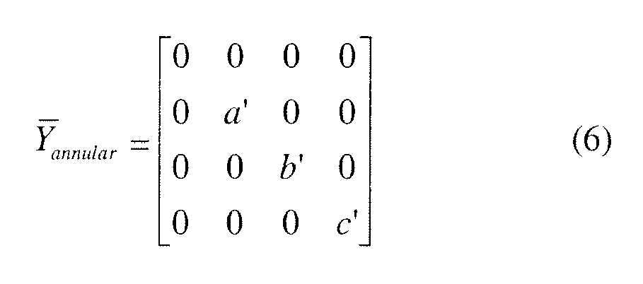
However, apart from the absolute values of the non-zero diagonal elements, a ratio of the different diagonal elements would provide an estimation of the size of the annulus. It should be noted that the elements along the diagonal in equation (6), of a', b' and c', are different from the case where a single homogenous material flows through the conduit. - In yet another embodiment, where the flow regime is bubbly, it can be said that the flow is not spatially symmetric and a good degree of asymmetry is present. In this case, the elements in the matrix
Y , except those present in the first row and first column may be non-zero as given byY bubbly matrix below :
The elements along the diagonal in equation (7), a" , b" and c" , are different from the case where a single homogenous material flows through the conduit. The absolute and relative values of the diagonal and non-diagonal elements can be used to identify the flow regime. -
FIG. 5 shows aplot 90 of variation of the element at the second row and second column of the matrixY , calledY (2,2), with increasing fraction of the secondary phase or material. Thehorizontal axis 91 represents the phase fraction of secondary phase and thevertical axis 92 represents values of element (2,2) of the matrixY . Thus, if the plot is stored in the computer, then by comparing the value of element (2,2) of the calculated matrixY with the stored plots, the phase fraction in the system can be determined. -
FIG. 6 shows aplot 94 of variation of the element at the second row and third column in matrixY , calledY (2,3) with increasing mean distance of the fraction of the secondary phase or material from the central axis of the conduit. Thehorizontal axis 95 represents the mean distance of the secondary phase from the central axis of the conduit and thevertical axis 96 represents the values of element (2,3) of the matrixY . Again, if these plots are stored in the computer, then in real time the mean distance of a concentrated bubble from the center of the pipe can be determined by comparing the value of element (2,3) of the calculated matrixY with the stored plots. - The data shown in
FIG. 5 andFIG. 6 may be obtained by several numerical simulations of randomly generated flow regimes and material distributions within the conduit that may be corrected based on experimental results. The values of other elements within theY matrix for different flow regimes and material distributions may be numerically calculated and/or empirically corrected. It should be noted that the other elements may have non-linear relations to the original distribution unlike the linear relationships shown in the graphs inFIG. 5 andFIG. 6 . -
FIG. 7 shows anoriginal distribution 97 and itsequivalent distribution 98 of the secondary phase visualized from the behavior of the various elements of theY matrix in accordance with an embodiment of the present invention. Theoriginal distribution 97 shown, for example is a bubbly flow distribution. From the current and voltage measurements made on electrodes placed around the conduit carrying this bubbly distribution, a Y matrix and subsequently aY matrix may be computed. As already shown, the elementY (2,2) represents the total fraction occupied by the secondary phase in the plane of the electrodes andY (2,3) represents the mean distance of the secondary phase from the central axis of the conduit. From these two elements of theY matrix, it is possible to equivalently represent the material distribution within the conduit as shown in theequivalent distribution 98. In theequivalent distribution 98, various distributedareas 99 of the secondary phase are combined into asingle area 100 and the mean distance of the single area of the secondary phase from the central axis of the conduit is shown by a variable R. It should be noted that the equivalent representation of the materials within the conduit is different from the result a full image processing or reconstruction algorithm would produce using the current and voltage information. The advantage of theequivalent distribution 98 is that while being a visual method of representing the original material distribution within the conduit, it does not increase the computation needed significantly. - In one embodiment, the elements of the
Y matrix from one or more sets of electrodes provide an indication of the velocity and density of various phases or materials within the conduit. These models may be coupled with numerical fluid dynamics models and electromagnetic models of multiphase flow in order to predict and correct the measurements in real-time. -
FIG. 8 is aflow chart 101 for a method of determining the characteristics of a multi-material object in accordance with one embodiment of the present invention. The method includes determining the electric element matrix representing the multi-material object instep 102. This can be achieved by a number of methods and may involve using the pseudo-inverse of an applied or measured electrical signal set, for example. Instep 104, the electric element matrix is pre-multiplied by a predefined first mathematical transformation matrix A to compute a first transformed electric element matrix. Instep 106, the first transformed electric element matrix is post-multiplied by a predefined second mathematical transformation matrix B to compute a second transformed electric element matrix. Instep 108, the characteristics of the multi-material object are determined from the analysis of the second transformed electric element matrix. The electric element matrix could be an impedance matrix or an admittance matrix representing the multi-material object, for example. -
FIG. 9 is aflow chart 110 for an analysis of a multi-material object that can be performed in accordance with one embodiment of the present invention. The method includes determining electric element matrix representing the multi-material object instep 112. Instep 114, the electric element matrix is pre-multiplied by a predefined first mathematical transformation matrix A to compute a first transformed electric element matrix. Instep 116, the first transformed electric element matrix is post-multiplied by a predefined second mathematical transformation matrix B to compute a second transformed electric element matrix. Instep 118, the characteristics of the multi-material object are determined from the analysis of the second transformed electric element matrix. Instep 120, an equivalent visual representation of the material distribution within the multi-material object is determined and displayed. One example of the equivalent visual representation is shown inFIG. 7 . -
FIG. 10 is aflow chart 130 for a method of determining the characteristics of a multi-material object based on an electrical signal set in accordance with an embodiment of the present invention. Since the electric element matrix can be determined from applied electrical signals and measured electrical signals, in one embodiment, it is possible to directly determine the characteristics of a multi-material object from the applied electrical signal set and the measured electrical signal set. The method includes providing an applied electrical signal set to the electrodes surrounding the multi-material object instep 132. Instep 134, a measured electrical signal set of measured electrical signals from the electrodes is obtained. In one embodiment, a current matrix I of measured current signals or a voltage matrix V of measured voltage signals from the electrodes is used directly (instead of having the intermediate step of forming the electric element matrix) to determine characteristics of the multi-material object. The currents are measured when voltages are applied to electrodes and voltages are measured when currents are applied to the electrodes. Instep 136, the measured electrical signal set is pre-multiplied by a predefined first mathematical transformation matrix A' to compute a first transformed measured electrical signal set. Instep 138, the first transformed second electrical signal set is post-multiplied by a predefined second mathematical transformation matrix B' to compute a second transformed measured electrical signal set. In such a case, the matrices A' and B' will have different values compared to A and B of method described inFIG. 8 . Instep 140, the characteristics of the multi-material object are determined from the analysis of the second transformed measured electrical signal set.
While only certain features of the invention have been illustrated and described herein, many modifications and changes will occur to those skilled in the art. It is, therefore, to be understood that the appended claims are intended to cover all such modifications and changes as fall within the true spirit of the invention.
Various aspects of the present invention are defined in the following numbered clauses: - 1. A method for determining characteristics of a multi-material object comprising:
- determining an electric element matrix representing the multi-material object;
- pre-multiplying the electric element matrix with a first mathematical transformation matrix to obtain a first transformed electric element matrix;
- post-multiplying the first transformed electric element matrix with a second mathematical transformation matrix to obtain a second transformed electric element matrix; and
- determining the characteristics of the multi-material object based on the second transformed electric element matrix.
- 2. The method of
clause 1, wherein the electric element matrix comprises an impedance matrix or an admittance matrix. - 3. The method of
clause 1 orclause 2, wherein the first mathematical transformation matrix and the second mathematical transformation matrix transform the coordinate system of the electric element matrix. - 4. The method of any preceding clause, wherein the first mathematical transformation matrix comprises a discrete Fourier transform matrix and the second mathematical transformation matrix comprises an inverse of the discrete Fourier transform matrix.
- 5. The method of any preceding clause, wherein the first mathematical transformation matrix comprises an identity matrix.
- 6. The method of any preceding clause, wherein the second mathematical transformation matrix comprises an identity matrix.
- 7. The method of any preceding clause, wherein determining the characteristics of the multi-material object comprises determining a spatial symmetry in the distribution of the materials within the multi-material object based on the elements along the diagonal of the second transformed impedance matrix and determining an asymmetry in the distribution of materials within the multi-material object based on the elements that do not lie along the diagonal of the second transformed impedance matrix.
- 8. The method of any preceding clause, wherein determining the characteristics of the multi-material object comprises determining a presence of current paths other than current paths through energized electrodes surrounding the multi-material object based on elements in the first row and the first column of the second transformed electric element matrix.
- 9. The method of any preceding clause, wherein determining the characteristics of the multi-material object comprises utilizing the information of the electric element matrix obtained from numerical simulations of randomly generated flow regimes and material distributions.
- 10. The method of any preceding clause, wherein determining the characteristics of the multi-material object comprises utilizing the information on the electric element matrix based on prior experimental results.
- 11. The method of any preceding clause, wherein elements not lying on the diagonal of the electric element matrix comprise zeros for a spatially symmetric flow regime.
- 12. The method of clause 11, wherein the spatially symmetric flow regime comprises at least one of a chum flow regime or an annular flow regime.
- 13. The method of any preceding clause, wherein elements not lying on the diagonal of the electric element matrix comprise non-zero values for an asymmetric flow regime.
- 14. The method of clause 13, wherein the asymmetric flow regime comprises a bubbly flow regime.
- 15. The method of any preceding clause, wherein characteristics of the multi-material object comprise compositions and distributions of different materials within the object.
- 16. The method of any preceding clause, wherein determining the characteristics of the multi-material object comprises determining flow regimes, volumetric fraction, density and velocity of the materials within the multi-material object.
- 17. The method of any preceding clause, further comprising determining an equivalent visual representation of the material distribution within the multi-material object.
- 18. The method of any preceding clause, wherein determining the characteristics of the multi-material object comprises determining flow regimes, volumetric fraction, density and velocity of the materials within the multi-material object based on the equivalent visual representation.
- 19. The method of any preceding clause, wherein determining the equivalent visual representation of the material distribution within the multi-material object comprises combining various distributed areas of the secondary phase into a single area.
- 20. A multi-material sensing system comprising:
- a power supply to provide an applied electrical signal set to electrodes surrounding a multi-material object;
- a measurement unit to obtain a measured electrical signal set from the electrodes; and
- processing circuitry to determine an electric element matrix based on the applied and measured electrical signal sets, to pre-multiply the electric element matrix with a first mathematical transformation matrix to obtain a first transformed electric element matrix, to post-multiply the first transformed electric element matrix with a second mathematical transformation matrix to obtain a second transformed electric element matrix and to determine the characteristics of the multi-material object based on the second transformed electric element matrix.
- 21. The system of
clause 20, wherein the power supply comprises a voltage source or a current source. - 22. The system of any preceding clause, wherein the measurement unit comprises a voltmeter or a current meter.
- 23. The method of any preceding clause, wherein the multi-material object comprises oil, water, and gas.
- 24. A method of determining characteristics of a multi-material object comprising:
- providing an applied electrical signal set to the electrodes surrounding the multi-material object;
- obtaining a measured electrical signal set of measured electrical signals from the electrodes;
- pre-multiplying the measured electrical signal set with a first mathematical transformation matrix to obtain a first transformed measured electrical signal set;
- post-multiplying the first transformed measured electrical signal set with a second mathematical transformation matrix to obtain a second transformed measured electrical signal set; and
- determining the characteristics of the multi-material object based on the second transformed measured electrical signal set.
Claims (10)
- A method (101) for determining characteristics of a multi-material object comprising:determining (102) an electric element matrix representing the multi-material object;pre-multiplying (104) the electric element matrix with a first mathematical transformation matrix to obtain a first transformed electric element matrix;post-multiplying (106) the first transformed electric element matrix with a second mathematical transformation matrix to obtain a second transformed electric element matrix; anddetermining (108) the characteristics of the multi-material object based on the second transformed electric element matrix.
- The method of claim 1, wherein the first mathematical transformation matrix comprises a discrete Fourier transform matrix and the second mathematical transformation matrix comprises an inverse of the discrete Fourier transform matrix.
- The method of claim 1 or claim 2, wherein determining the characteristics of the multi-material object comprises determining a spatial symmetry in the distribution of the materials within the multi-material object based on the elements along the diagonal of the second transformed impedance matrix and determining an asymmetry in the distribution of materials within the multi-material object based on the elements that do not lie along the diagonal of the second transformed impedance matrix.
- The method of any preceding claim, wherein determining the characteristics of the multi-material object comprises utilizing the information of the electric element matrix obtained from numerical simulations of randomly generated flow regimes and material distributions.
- The method of any preceding claim, wherein determining the characteristics of the multi-material object comprises utilizing the information on the electric element matrix based on prior experimental results.
- The method of any preceding claim, wherein characteristics of the multi-material object comprise compositions and distributions of different materials within the object.
- The method of any preceding claim, wherein determining the characteristics of the multi-material object comprises determining flow regimes, volumetric fraction, density and velocity of the materials within the multi-material object.
- The method of any preceding claim, further comprising determining an equivalent visual representation of the material distribution within the multi-material object.
- A multi-material sensing system (40) comprising:a power supply (62) to provide an applied electrical signal set to electrodes surrounding a multi-material object;a measurement unit (62) to obtain a measured electrical signal set from the electrodes; andprocessing circuitry (50) to determine an electric element matrix based on the applied and measured electrical signal sets, to pre-multiply the electric element matrix with a first mathematical transformation matrix to obtain a first transformed electric element matrix, to post-multiply the first transformed electric element matrix with a second mathematical transformation matrix to obtain a second transformed electric element matrix and to determine the characteristics of the multi-material object based on the second transformed electric element matrix.
- A method (130) of determining characteristics of a multi-material object comprising:providing (132) an applied electrical signal set to the electrodes surrounding the multi-matetial object;obtaining (134) a measured electrical signal set of measured electrical signals from the electrodes;pre-multiplying (136) the measured electrical signal set with a first mathematical transformation matrix to obtain a first transformed measured electrical signal set;post-multiplying (138) the first transformed measured electrical signal set with a second mathematical transformation matrix to obtain a second transformed measured electrical signal set; anddetermining (140) the characteristics of the multi-material object based on the second transformed measured electrical signal set.
Applications Claiming Priority (1)
| Application Number | Priority Date | Filing Date | Title |
|---|---|---|---|
| US12/652,120 US8121804B2 (en) | 2010-01-05 | 2010-01-05 | Electrical network analysis of a multiphase system |
Publications (3)
| Publication Number | Publication Date |
|---|---|
| EP2343538A2 true EP2343538A2 (en) | 2011-07-13 |
| EP2343538A3 EP2343538A3 (en) | 2012-09-26 |
| EP2343538B1 EP2343538B1 (en) | 2017-02-22 |
Family
ID=43799518
Family Applications (1)
| Application Number | Title | Priority Date | Filing Date |
|---|---|---|---|
| EP10196465.8A Not-in-force EP2343538B1 (en) | 2010-01-05 | 2010-12-22 | Electrical network analysis of a multiphase system |
Country Status (5)
| Country | Link |
|---|---|
| US (1) | US8121804B2 (en) |
| EP (1) | EP2343538B1 (en) |
| JP (1) | JP5789099B2 (en) |
| CN (1) | CN102183547B (en) |
| BR (1) | BRPI1100571B8 (en) |
Cited By (4)
| Publication number | Priority date | Publication date | Assignee | Title |
|---|---|---|---|---|
| GB2513678A (en) * | 2013-04-30 | 2014-11-05 | Iphase Ltd | Method and apparatus for monitoring the flow of mixtures of fluids in a pipe |
| GB2546522A (en) * | 2016-01-21 | 2017-07-26 | Atout Process Ltd | Method and apparatus for measuring flows |
| US10371656B2 (en) | 2014-09-15 | 2019-08-06 | University Of Leeds | Tomography apparatus and method |
| US10732017B2 (en) | 2014-09-15 | 2020-08-04 | University Of Leeds | Tomography apparatus, multi-phase flow monitoring system, and corresponding methods |
Families Citing this family (3)
| Publication number | Priority date | Publication date | Assignee | Title |
|---|---|---|---|---|
| CN106770479A (en) * | 2016-12-09 | 2017-05-31 | 中国科学院合肥物质科学研究院 | Prepare anisotropic conductive composite solidification process detecting system |
| AU2017387061B2 (en) | 2016-12-27 | 2019-08-22 | Panametrics Llc | Portable moisture analyzer for natural gas |
| USD822514S1 (en) | 2016-12-27 | 2018-07-10 | General Electric Company | Portable natural gas moisture analyzer |
Family Cites Families (12)
| Publication number | Priority date | Publication date | Assignee | Title |
|---|---|---|---|---|
| US4063153A (en) * | 1976-08-31 | 1977-12-13 | Auburn International, Inc. | Vapor liquid fraction determination |
| GB2227841B (en) * | 1988-12-03 | 1993-05-12 | Schlumberger Ltd | Impedance cross correlation logging tool |
| GB9109957D0 (en) * | 1991-05-08 | 1991-07-03 | Schlumberger Ltd | Capacitance flow meter |
| US5396806A (en) * | 1993-11-12 | 1995-03-14 | Auburn International, Inc. | On-line mass flow measurement in flowing two component systems |
| EP1347706B1 (en) * | 2000-12-30 | 2008-05-21 | The University Of Leeds | Electrical impedance tomography |
| ES2234794T3 (en) * | 2001-07-16 | 2005-07-01 | Axa Power A/S | COMPENSATION OF THE CABLE VOLTAGE FALL IN AN ELECTRICAL POWER SUPPLY SYSTEM. |
| US20030085715A1 (en) * | 2001-08-15 | 2003-05-08 | David Lubkeman | System and method for locating a fault on ungrounded and high-impedance grounded power systems |
| US7167009B2 (en) * | 2002-04-16 | 2007-01-23 | Mide Technology Corporation | Method and apparatus for determining electrical properties of structures |
| AU2003900857A0 (en) * | 2003-02-26 | 2003-03-13 | Commonwealth Scientific And Industrial Research Organisation | Method and apparatus for characterising multiphase fluid mixtures |
| US7496450B2 (en) * | 2003-08-22 | 2009-02-24 | Instituto Mexicano Del Petroleo | Method for imaging multiphase flow using electrical capacitance tomography |
| US7526966B2 (en) * | 2005-05-27 | 2009-05-05 | Expro Meters, Inc. | Apparatus and method for measuring a parameter of a multiphase flow |
| CN101241094B (en) * | 2008-03-12 | 2011-03-23 | 天津大学 | Non-contact type electric impedance sensor and image rebuilding method based on the sensor |
-
2010
- 2010-01-05 US US12/652,120 patent/US8121804B2/en not_active Expired - Fee Related
- 2010-12-22 EP EP10196465.8A patent/EP2343538B1/en not_active Not-in-force
- 2010-12-27 JP JP2010289717A patent/JP5789099B2/en not_active Expired - Fee Related
-
2011
- 2011-01-04 BR BRPI1100571A patent/BRPI1100571B8/en not_active IP Right Cessation
- 2011-01-05 CN CN201110008556.1A patent/CN102183547B/en not_active Expired - Fee Related
Non-Patent Citations (1)
| Title |
|---|
| None |
Cited By (10)
| Publication number | Priority date | Publication date | Assignee | Title |
|---|---|---|---|---|
| GB2513678A (en) * | 2013-04-30 | 2014-11-05 | Iphase Ltd | Method and apparatus for monitoring the flow of mixtures of fluids in a pipe |
| GB2513678B (en) * | 2013-04-30 | 2017-02-22 | Iphase Ltd | Oil well system and operating method including monitoring multi-phase flow in a pipe |
| US10378941B2 (en) | 2013-04-30 | 2019-08-13 | Iphase Limited | Method and apparatus for monitoring the flow of mixtures of fluid in a pipe |
| US10739177B2 (en) | 2013-04-30 | 2020-08-11 | Iphase Limited | Method and apparatus for monitoring the flow of mixtures of fluids in a pipe |
| US10753778B2 (en) | 2013-04-30 | 2020-08-25 | Iphase Limited | Method and apparatus for monitoring the flow of mixtures of fluids in a pipe |
| US10371656B2 (en) | 2014-09-15 | 2019-08-06 | University Of Leeds | Tomography apparatus and method |
| US10732017B2 (en) | 2014-09-15 | 2020-08-04 | University Of Leeds | Tomography apparatus, multi-phase flow monitoring system, and corresponding methods |
| GB2546522A (en) * | 2016-01-21 | 2017-07-26 | Atout Process Ltd | Method and apparatus for measuring flows |
| US10551289B2 (en) | 2016-01-21 | 2020-02-04 | Atout Process Limited | Method and apparatus for determining properties of a contained fluid |
| GB2546522B (en) * | 2016-01-21 | 2020-02-12 | Atout Process Ltd | Method and apparatus for measuring flows |
Also Published As
| Publication number | Publication date |
|---|---|
| JP2011141872A (en) | 2011-07-21 |
| CN102183547A (en) | 2011-09-14 |
| US8121804B2 (en) | 2012-02-21 |
| EP2343538B1 (en) | 2017-02-22 |
| EP2343538A3 (en) | 2012-09-26 |
| US20110166814A1 (en) | 2011-07-07 |
| CN102183547B (en) | 2014-11-19 |
| BRPI1100571A2 (en) | 2013-04-24 |
| BRPI1100571B1 (en) | 2020-04-22 |
| JP5789099B2 (en) | 2015-10-07 |
| BRPI1100571B8 (en) | 2020-05-19 |
Similar Documents
| Publication | Publication Date | Title |
|---|---|---|
| EP2343539B1 (en) | Electrical network representation of a distributed system | |
| US8508238B2 (en) | System and method for performing electrical impedance tomography | |
| EP2343538B1 (en) | Electrical network analysis of a multiphase system | |
| US8054094B1 (en) | Image reconstruction based constrained maximization | |
| Kipping et al. | Developments for the application of the Wire-Mesh Sensor in industries | |
| Wang et al. | A new visualisation and measurement technology for water continuous multiphase flows | |
| RU2590321C2 (en) | System and method for reconstruction with "soft field" | |
| Muhamedsalih et al. | A two-phase flow meter for determining water and solids volumetric flow rates in stratified, inclined solids-in-water flows | |
| Ru et al. | Neural networks in electrical capacitance tomography (ECT)-based interface detection | |
| Yang et al. | The proposal and calculation method of the annular domain weight function for the electromagnetic flowmeter under annular conductivity distribution | |
| Tan et al. | Data fusion for measurement of water holdup in horizontal pipes by conductivity rings | |
| Wang et al. | Large-scale electrical tomography sensing system to study mixing phenomena | |
| Tan et al. | Cross correlation based dispersed phase velocity profile measurement of two-phase pipe flow | |
| Shi et al. | Design and implementation of a multi-sensor system for gas–water flow measurement | |
| Faizatul Khasanah Sugeng | Two Phase Flow By Using Electrical Tomography | |
| Sugeng et al. | TWO PHASE FLOW USING ELECTRICAL TOMOGRAPHY | |
| Yua et al. | Extracting Homogenous Reference Voltages from Heterogeneous Measurement Voltages for Oil-water Two-phase Flow Measurement of Electrical Impedance Tomography |
Legal Events
| Date | Code | Title | Description |
|---|---|---|---|
| PUAI | Public reference made under article 153(3) epc to a published international application that has entered the european phase |
Free format text: ORIGINAL CODE: 0009012 |
|
| AK | Designated contracting states |
Kind code of ref document: A2 Designated state(s): AL AT BE BG CH CY CZ DE DK EE ES FI FR GB GR HR HU IE IS IT LI LT LU LV MC MK MT NL NO PL PT RO RS SE SI SK SM TR |
|
| AX | Request for extension of the european patent |
Extension state: BA ME |
|
| PUAL | Search report despatched |
Free format text: ORIGINAL CODE: 0009013 |
|
| AK | Designated contracting states |
Kind code of ref document: A3 Designated state(s): AL AT BE BG CH CY CZ DE DK EE ES FI FR GB GR HR HU IE IS IT LI LT LU LV MC MK MT NL NO PL PT RO RS SE SI SK SM TR |
|
| AX | Request for extension of the european patent |
Extension state: BA ME |
|
| RIC1 | Information provided on ipc code assigned before grant |
Ipc: G01N 33/28 20060101ALI20120822BHEP Ipc: G01N 27/02 20060101AFI20120822BHEP |
|
| 17P | Request for examination filed |
Effective date: 20130326 |
|
| 17Q | First examination report despatched |
Effective date: 20130417 |
|
| GRAP | Despatch of communication of intention to grant a patent |
Free format text: ORIGINAL CODE: EPIDOSNIGR1 |
|
| INTG | Intention to grant announced |
Effective date: 20160930 |
|
| GRAS | Grant fee paid |
Free format text: ORIGINAL CODE: EPIDOSNIGR3 |
|
| GRAA | (expected) grant |
Free format text: ORIGINAL CODE: 0009210 |
|
| AK | Designated contracting states |
Kind code of ref document: B1 Designated state(s): AL AT BE BG CH CY CZ DE DK EE ES FI FR GB GR HR HU IE IS IT LI LT LU LV MC MK MT NL NO PL PT RO RS SE SI SK SM TR |
|
| REG | Reference to a national code |
Ref country code: GB Ref legal event code: FG4D |
|
| REG | Reference to a national code |
Ref country code: CH Ref legal event code: EP |
|
| REG | Reference to a national code |
Ref country code: AT Ref legal event code: REF Ref document number: 869640 Country of ref document: AT Kind code of ref document: T Effective date: 20170315 |
|
| REG | Reference to a national code |
Ref country code: IE Ref legal event code: FG4D |
|
| REG | Reference to a national code |
Ref country code: DE Ref legal event code: R096 Ref document number: 602010040182 Country of ref document: DE |
|
| REG | Reference to a national code |
Ref country code: NO Ref legal event code: T2 Effective date: 20170222 |
|
| REG | Reference to a national code |
Ref country code: LT Ref legal event code: MG4D |
|
| REG | Reference to a national code |
Ref country code: NL Ref legal event code: MP Effective date: 20170222 |
|
| REG | Reference to a national code |
Ref country code: AT Ref legal event code: MK05 Ref document number: 869640 Country of ref document: AT Kind code of ref document: T Effective date: 20170222 |
|
| PG25 | Lapsed in a contracting state [announced via postgrant information from national office to epo] |
Ref country code: FI Free format text: LAPSE BECAUSE OF FAILURE TO SUBMIT A TRANSLATION OF THE DESCRIPTION OR TO PAY THE FEE WITHIN THE PRESCRIBED TIME-LIMIT Effective date: 20170222 Ref country code: GR Free format text: LAPSE BECAUSE OF FAILURE TO SUBMIT A TRANSLATION OF THE DESCRIPTION OR TO PAY THE FEE WITHIN THE PRESCRIBED TIME-LIMIT Effective date: 20170523 Ref country code: LT Free format text: LAPSE BECAUSE OF FAILURE TO SUBMIT A TRANSLATION OF THE DESCRIPTION OR TO PAY THE FEE WITHIN THE PRESCRIBED TIME-LIMIT Effective date: 20170222 Ref country code: HR Free format text: LAPSE BECAUSE OF FAILURE TO SUBMIT A TRANSLATION OF THE DESCRIPTION OR TO PAY THE FEE WITHIN THE PRESCRIBED TIME-LIMIT Effective date: 20170222 |
|
| PG25 | Lapsed in a contracting state [announced via postgrant information from national office to epo] |
Ref country code: SE Free format text: LAPSE BECAUSE OF FAILURE TO SUBMIT A TRANSLATION OF THE DESCRIPTION OR TO PAY THE FEE WITHIN THE PRESCRIBED TIME-LIMIT Effective date: 20170222 Ref country code: RS Free format text: LAPSE BECAUSE OF FAILURE TO SUBMIT A TRANSLATION OF THE DESCRIPTION OR TO PAY THE FEE WITHIN THE PRESCRIBED TIME-LIMIT Effective date: 20170222 Ref country code: AT Free format text: LAPSE BECAUSE OF FAILURE TO SUBMIT A TRANSLATION OF THE DESCRIPTION OR TO PAY THE FEE WITHIN THE PRESCRIBED TIME-LIMIT Effective date: 20170222 Ref country code: PT Free format text: LAPSE BECAUSE OF FAILURE TO SUBMIT A TRANSLATION OF THE DESCRIPTION OR TO PAY THE FEE WITHIN THE PRESCRIBED TIME-LIMIT Effective date: 20170622 Ref country code: BG Free format text: LAPSE BECAUSE OF FAILURE TO SUBMIT A TRANSLATION OF THE DESCRIPTION OR TO PAY THE FEE WITHIN THE PRESCRIBED TIME-LIMIT Effective date: 20170522 Ref country code: NL Free format text: LAPSE BECAUSE OF FAILURE TO SUBMIT A TRANSLATION OF THE DESCRIPTION OR TO PAY THE FEE WITHIN THE PRESCRIBED TIME-LIMIT Effective date: 20170222 Ref country code: LV Free format text: LAPSE BECAUSE OF FAILURE TO SUBMIT A TRANSLATION OF THE DESCRIPTION OR TO PAY THE FEE WITHIN THE PRESCRIBED TIME-LIMIT Effective date: 20170222 Ref country code: ES Free format text: LAPSE BECAUSE OF FAILURE TO SUBMIT A TRANSLATION OF THE DESCRIPTION OR TO PAY THE FEE WITHIN THE PRESCRIBED TIME-LIMIT Effective date: 20170222 |
|
| PG25 | Lapsed in a contracting state [announced via postgrant information from national office to epo] |
Ref country code: SK Free format text: LAPSE BECAUSE OF FAILURE TO SUBMIT A TRANSLATION OF THE DESCRIPTION OR TO PAY THE FEE WITHIN THE PRESCRIBED TIME-LIMIT Effective date: 20170222 Ref country code: IT Free format text: LAPSE BECAUSE OF FAILURE TO SUBMIT A TRANSLATION OF THE DESCRIPTION OR TO PAY THE FEE WITHIN THE PRESCRIBED TIME-LIMIT Effective date: 20170222 Ref country code: EE Free format text: LAPSE BECAUSE OF FAILURE TO SUBMIT A TRANSLATION OF THE DESCRIPTION OR TO PAY THE FEE WITHIN THE PRESCRIBED TIME-LIMIT Effective date: 20170222 Ref country code: RO Free format text: LAPSE BECAUSE OF FAILURE TO SUBMIT A TRANSLATION OF THE DESCRIPTION OR TO PAY THE FEE WITHIN THE PRESCRIBED TIME-LIMIT Effective date: 20170222 Ref country code: CZ Free format text: LAPSE BECAUSE OF FAILURE TO SUBMIT A TRANSLATION OF THE DESCRIPTION OR TO PAY THE FEE WITHIN THE PRESCRIBED TIME-LIMIT Effective date: 20170222 |
|
| REG | Reference to a national code |
Ref country code: DE Ref legal event code: R097 Ref document number: 602010040182 Country of ref document: DE |
|
| PG25 | Lapsed in a contracting state [announced via postgrant information from national office to epo] |
Ref country code: PL Free format text: LAPSE BECAUSE OF FAILURE TO SUBMIT A TRANSLATION OF THE DESCRIPTION OR TO PAY THE FEE WITHIN THE PRESCRIBED TIME-LIMIT Effective date: 20170222 Ref country code: DK Free format text: LAPSE BECAUSE OF FAILURE TO SUBMIT A TRANSLATION OF THE DESCRIPTION OR TO PAY THE FEE WITHIN THE PRESCRIBED TIME-LIMIT Effective date: 20170222 Ref country code: SM Free format text: LAPSE BECAUSE OF FAILURE TO SUBMIT A TRANSLATION OF THE DESCRIPTION OR TO PAY THE FEE WITHIN THE PRESCRIBED TIME-LIMIT Effective date: 20170222 |
|
| PLBE | No opposition filed within time limit |
Free format text: ORIGINAL CODE: 0009261 |
|
| STAA | Information on the status of an ep patent application or granted ep patent |
Free format text: STATUS: NO OPPOSITION FILED WITHIN TIME LIMIT |
|
| 26N | No opposition filed |
Effective date: 20171123 |
|
| PG25 | Lapsed in a contracting state [announced via postgrant information from national office to epo] |
Ref country code: SI Free format text: LAPSE BECAUSE OF FAILURE TO SUBMIT A TRANSLATION OF THE DESCRIPTION OR TO PAY THE FEE WITHIN THE PRESCRIBED TIME-LIMIT Effective date: 20170222 |
|
| REG | Reference to a national code |
Ref country code: DE Ref legal event code: R119 Ref document number: 602010040182 Country of ref document: DE |
|
| REG | Reference to a national code |
Ref country code: CH Ref legal event code: PL |
|
| REG | Reference to a national code |
Ref country code: IE Ref legal event code: MM4A |
|
| PG25 | Lapsed in a contracting state [announced via postgrant information from national office to epo] |
Ref country code: MT Free format text: LAPSE BECAUSE OF NON-PAYMENT OF DUE FEES Effective date: 20171222 Ref country code: LU Free format text: LAPSE BECAUSE OF NON-PAYMENT OF DUE FEES Effective date: 20171222 |
|
| REG | Reference to a national code |
Ref country code: FR Ref legal event code: ST Effective date: 20180831 |
|
| REG | Reference to a national code |
Ref country code: BE Ref legal event code: MM Effective date: 20171231 |
|
| PG25 | Lapsed in a contracting state [announced via postgrant information from national office to epo] |
Ref country code: IE Free format text: LAPSE BECAUSE OF NON-PAYMENT OF DUE FEES Effective date: 20171222 Ref country code: FR Free format text: LAPSE BECAUSE OF NON-PAYMENT OF DUE FEES Effective date: 20180102 Ref country code: DE Free format text: LAPSE BECAUSE OF NON-PAYMENT OF DUE FEES Effective date: 20180703 |
|
| PG25 | Lapsed in a contracting state [announced via postgrant information from national office to epo] |
Ref country code: LI Free format text: LAPSE BECAUSE OF NON-PAYMENT OF DUE FEES Effective date: 20171231 Ref country code: CH Free format text: LAPSE BECAUSE OF NON-PAYMENT OF DUE FEES Effective date: 20171231 Ref country code: BE Free format text: LAPSE BECAUSE OF NON-PAYMENT OF DUE FEES Effective date: 20171231 |
|
| PG25 | Lapsed in a contracting state [announced via postgrant information from national office to epo] |
Ref country code: HU Free format text: LAPSE BECAUSE OF FAILURE TO SUBMIT A TRANSLATION OF THE DESCRIPTION OR TO PAY THE FEE WITHIN THE PRESCRIBED TIME-LIMIT; INVALID AB INITIO Effective date: 20101222 Ref country code: MC Free format text: LAPSE BECAUSE OF FAILURE TO SUBMIT A TRANSLATION OF THE DESCRIPTION OR TO PAY THE FEE WITHIN THE PRESCRIBED TIME-LIMIT Effective date: 20170222 |
|
| PG25 | Lapsed in a contracting state [announced via postgrant information from national office to epo] |
Ref country code: CY Free format text: LAPSE BECAUSE OF NON-PAYMENT OF DUE FEES Effective date: 20170222 |
|
| PG25 | Lapsed in a contracting state [announced via postgrant information from national office to epo] |
Ref country code: MK Free format text: LAPSE BECAUSE OF FAILURE TO SUBMIT A TRANSLATION OF THE DESCRIPTION OR TO PAY THE FEE WITHIN THE PRESCRIBED TIME-LIMIT Effective date: 20170222 |
|
| PG25 | Lapsed in a contracting state [announced via postgrant information from national office to epo] |
Ref country code: TR Free format text: LAPSE BECAUSE OF FAILURE TO SUBMIT A TRANSLATION OF THE DESCRIPTION OR TO PAY THE FEE WITHIN THE PRESCRIBED TIME-LIMIT Effective date: 20170222 |
|
| PG25 | Lapsed in a contracting state [announced via postgrant information from national office to epo] |
Ref country code: AL Free format text: LAPSE BECAUSE OF FAILURE TO SUBMIT A TRANSLATION OF THE DESCRIPTION OR TO PAY THE FEE WITHIN THE PRESCRIBED TIME-LIMIT Effective date: 20170222 Ref country code: IS Free format text: LAPSE BECAUSE OF FAILURE TO SUBMIT A TRANSLATION OF THE DESCRIPTION OR TO PAY THE FEE WITHIN THE PRESCRIBED TIME-LIMIT Effective date: 20170622 |
|
| PGFP | Annual fee paid to national office [announced via postgrant information from national office to epo] |
Ref country code: GB Payment date: 20201123 Year of fee payment: 11 Ref country code: NO Payment date: 20201123 Year of fee payment: 11 |
|
| REG | Reference to a national code |
Ref country code: NO Ref legal event code: MMEP |
|
| GBPC | Gb: european patent ceased through non-payment of renewal fee |
Effective date: 20211222 |
|
| PG25 | Lapsed in a contracting state [announced via postgrant information from national office to epo] |
Ref country code: NO Free format text: LAPSE BECAUSE OF NON-PAYMENT OF DUE FEES Effective date: 20211231 Ref country code: GB Free format text: LAPSE BECAUSE OF NON-PAYMENT OF DUE FEES Effective date: 20211222 |