EP2343462A1 - Linear bearing with sliding film - Google Patents
Linear bearing with sliding film Download PDFInfo
- Publication number
- EP2343462A1 EP2343462A1 EP11150417A EP11150417A EP2343462A1 EP 2343462 A1 EP2343462 A1 EP 2343462A1 EP 11150417 A EP11150417 A EP 11150417A EP 11150417 A EP11150417 A EP 11150417A EP 2343462 A1 EP2343462 A1 EP 2343462A1
- Authority
- EP
- European Patent Office
- Prior art keywords
- sliding film
- positioning
- retainer
- linear bearing
- grooves
- Prior art date
- Legal status (The legal status is an assumption and is not a legal conclusion. Google has not performed a legal analysis and makes no representation as to the accuracy of the status listed.)
- Granted
Links
- 229920003023 plastic Polymers 0.000 claims description 16
- 238000000926 separation method Methods 0.000 claims description 10
- 238000003889 chemical engineering Methods 0.000 abstract description 2
- 239000003814 drug Substances 0.000 abstract description 2
- 238000012545 processing Methods 0.000 abstract description 2
- 230000002035 prolonged effect Effects 0.000 abstract description 2
- 238000012986 modification Methods 0.000 description 2
- 230000004048 modification Effects 0.000 description 2
- 239000003607 modifier Substances 0.000 description 2
- 230000003247 decreasing effect Effects 0.000 description 1
- 238000013461 design Methods 0.000 description 1
- 229920006351 engineering plastic Polymers 0.000 description 1
- 238000005516 engineering process Methods 0.000 description 1
- 238000001746 injection moulding Methods 0.000 description 1
- 238000012423 maintenance Methods 0.000 description 1
- 238000004519 manufacturing process Methods 0.000 description 1
- 238000000034 method Methods 0.000 description 1
- 239000000203 mixture Substances 0.000 description 1
- 239000012783 reinforcing fiber Substances 0.000 description 1
Images


Classifications
-
- F—MECHANICAL ENGINEERING; LIGHTING; HEATING; WEAPONS; BLASTING
- F16—ENGINEERING ELEMENTS AND UNITS; GENERAL MEASURES FOR PRODUCING AND MAINTAINING EFFECTIVE FUNCTIONING OF MACHINES OR INSTALLATIONS; THERMAL INSULATION IN GENERAL
- F16C—SHAFTS; FLEXIBLE SHAFTS; ELEMENTS OR CRANKSHAFT MECHANISMS; ROTARY BODIES OTHER THAN GEARING ELEMENTS; BEARINGS
- F16C29/00—Bearings for parts moving only linearly
- F16C29/02—Sliding-contact bearings
-
- F—MECHANICAL ENGINEERING; LIGHTING; HEATING; WEAPONS; BLASTING
- F16—ENGINEERING ELEMENTS AND UNITS; GENERAL MEASURES FOR PRODUCING AND MAINTAINING EFFECTIVE FUNCTIONING OF MACHINES OR INSTALLATIONS; THERMAL INSULATION IN GENERAL
- F16C—SHAFTS; FLEXIBLE SHAFTS; ELEMENTS OR CRANKSHAFT MECHANISMS; ROTARY BODIES OTHER THAN GEARING ELEMENTS; BEARINGS
- F16C33/00—Parts of bearings; Special methods for making bearings or parts thereof
- F16C33/02—Parts of sliding-contact bearings
- F16C33/04—Brasses; Bushes; Linings
- F16C33/06—Sliding surface mainly made of metal
- F16C33/08—Attachment of brasses, bushes or linings to the bearing housing
-
- F—MECHANICAL ENGINEERING; LIGHTING; HEATING; WEAPONS; BLASTING
- F16—ENGINEERING ELEMENTS AND UNITS; GENERAL MEASURES FOR PRODUCING AND MAINTAINING EFFECTIVE FUNCTIONING OF MACHINES OR INSTALLATIONS; THERMAL INSULATION IN GENERAL
- F16C—SHAFTS; FLEXIBLE SHAFTS; ELEMENTS OR CRANKSHAFT MECHANISMS; ROTARY BODIES OTHER THAN GEARING ELEMENTS; BEARINGS
- F16C33/00—Parts of bearings; Special methods for making bearings or parts thereof
- F16C33/02—Parts of sliding-contact bearings
- F16C33/04—Brasses; Bushes; Linings
- F16C33/06—Sliding surface mainly made of metal
- F16C33/10—Construction relative to lubrication
- F16C33/1025—Construction relative to lubrication with liquid, e.g. oil, as lubricant
- F16C33/106—Details of distribution or circulation inside the bearings, e.g. details of the bearing surfaces to affect flow or pressure of the liquid
- F16C33/107—Grooves for generating pressure
Definitions
- the invention relates to a linear bearing with a sliding film, and more particular to a self-lubricating plastic linear bearing having a rotatable sliding film with spiral grooves.
- the linear bearing has an infinite stroke and is fitted with a cylinder shaft.
- the conventional plastic linear bearing includes a tubular retainer.
- a plastic sliding film is attached to the inner wall of the retainer.
- a positioning groove is formed on the inner circumferential wall of the retainer, and positioning holes are formed at the bottom of the groove.
- the sliding film includes thin plastic plates connected with each other.
- the sliding film is provided with positioning bosses distributed equispacedly at the fit position between the sliding film and the positioning groove of the retainer, and positioning pins fitted with the positioning holes are provided on the positioning bosses.
- the sliding film is rolled into a cylinder and then placed in the hole of the retainer. Grooves between these connected thin plastic plates are parallel to the axis of the tubular retainer.
- the object of the invention is to provide a self-lubricating plastic linear bearing having a rotatable sliding film with spiral grooves, which has a simple manufacture technology, a low cost, a light weight and a long service life, and may be installed and operated easily.
- the invention provides a linear bearing with a sliding film.
- the bearing includes a tubular retainer.
- the sliding film is attached to an inner circumferential wall of the retainer, and grooves are provided on an inner circumferential surface of the sliding film.
- An axial positioning structure and a circumferential positioning structure are provided between the sliding film and the retainer.
- the grooves are spiral grooves.
- a separation angle between a tangent line of each groove and a central axis of the retainer is ranged from 3° to 30°.
- a separation angle between a tangent line of a seam of the sliding film and the central axis of the retainer is the same as the separation angle between the tangent line of the groove and the central axis of the retainer.
- the axial positioning structure comprises two flanged edges respectively provided at both ends of the sliding film and holding both end surfaces of the retainer
- the circumferential positioning structure includes at least two positioning grooves or positioning holes provided on at least one of the flanged edges and staggered in a circumferential direction. At least one positioning pin connected to the retainer is fitted in the positioning grooves or positioning holes.
- a radial dimension of one of the two flanged edges is larger than that of the other one.
- the positioning grooves or positioning holes are provided on the flanged edge having a larger radial dimension.
- the sliding film is a self-lubricating plastic sliding film.
- the axial positioning structure comprises a positioning groove provided on an inner wall of the retainer and a positioning rib provided on an outer circumferential surface of the sliding film and protruding from the outer circumferential surface and matched with the positioning groove.
- the circumferential positioning structure comprises a positioning hole provided at the bottom of the positioning groove and a recess provided on the positioning rib and corresponding to the positioning hole.
- a positioning pin which may be received in the recess is installed in the positioning hole.
- the plastic linear bearing When being used after a period of time, it is possible to eliminate the phenomenon that the plastic linear bearing is always in contact with the shaft and is worn by the shaft at the same position through rotating the sliding film relative to the retainer by a certain angle. After the sliding film is rotated, its worn bearing surface which is in contact with the shaft previously is replaced with a new contact surface which is not or less worn. Thus, the whole inner wall of the sliding film may contacts with the shaft alternately by a plurality of times of the rotation of the sliding film. Therefore, the service life of the whole plastic linear bearing is significantly prolonged.
- the bearing may be widely used in mechanical devices for chemical engineering, medicine, instrument, meter, aeronautics, astronautics, food processing and the like.
- Fig. 1 is a front view of a linear bearing with a sliding film in a first embodiment
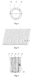
- Fig. 2 is a bottom view of Fig. 1 ;
- Fig. 3 is a front view of a sliding film in the first embodiment
- Fig. 4 is a bottom view of Fig. 3 ;
- Fig. 5 is an unfolded view of Fig. 3 ;
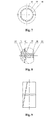
- Fig. 6 is a front view of a linear bearing with a sliding film in a second embodiment
- Fig. 7 is a bottom view of Fig. 6 ;
- Fig. 8 is a partial enlarged view of region A in Fig. 6 ;
- Fig. 9 is a front view of a sliding film in the second embodiment.
- Fig. 10 is an unfolded view of the inner surface of the sliding film in the second embodiment.
- Fig. 11 is an unfolded view of the outer surface of the sliding film in the second embodiment.
- Figs. 1 and 2 are structural views of a self-lubricating plastic linear bearing having a rotatable sliding film with spiral grooves.
- the bearing includes a tubular retainer 1.
- a self-lubricating plastic sliding film 2 is attached to the inner wall of the retainer 1.
- the sliding film 2 is formed of a mixture containing an engineering plastic, an inorganic modifier, organic modifier, reinforcing fibers and a lubricator by injection molding.
- spiral grooves 3 are formed on the inner circumferential surface of the sliding film 2.
- the separation angle A between the tangent line of each groove 3 and the central axis of the retainer is ranged from 3° to 30°.
- the sliding film 2 is rolled into a cylinder and then attached to the inner wall of a hole of the retainer 1.
- the separation angle between the tangent line of a seam of the rolled sliding film 2 and the central axis of the retainer is the same as the separation angle A between the tangent line of the groove and the central axis of the retainer.
- the sliding film 2 is provided with an axial positioning structure and a circumferential positioning structure relative to the retainer 1.
- the axial positioning structure includes outer flanged edges 5 at both ends of the sliding film 2. Both end surfaces of the retainer 1 are held by the flanged edges 5 at both ends, respectively.
- the circumferential positioning structure includes at least two staggered positioning grooves or positioning holes 6 provided in the flanged edge 5, e.g., two opposite positioning grooves or positioning holes 6, or four positioning grooves or positioning holes 6 as shown in Fig. 2 .
- At least one positioning pin 7 fixed on the retainer 1 is fitted in the positioning grooves or positioning holes 6.
- One flanged edge 5 located at one end of the sliding film 2 is larger than the other flanged edge 5 located at the other end of the sliding film 2.
- the positioning grooves or positioning holes 6 are disposed in the larger flanged edge 5.
- Figs. 6-8 are structural views of a plastic sliding film bearing.
- the bearing includes a tubular retainer 10.
- a plastic sliding film 20 is attached to the inner wall of the retainer 10.
- the sliding film 20 is rolled into a cylinder and then attached to the inner wall of a hole of the retainer 10.
- a positioning groove 30 is provided on the circumference of the inner wall of the retainer 10, and a positioning rib 40 protruding from the outer circumferential surface and matched with the positioning groove 30 is provided on the outer circumferential surface of the sliding film 20, so as to achieve an axial positioning between the retainer 10 and the sliding film 20.
- Grooves 50 are formed on the circumferential surface of the inner wall of the sliding film 20.
- the separation angle A between the tangent line of each groove 50 and the central axis of the retainer 10 is ranged from 3° to 30°.
- a positioning hole 60 may provided at the bottom of the positioning groove 30 of the retainer 10, and a recess 70 corresponding to the positioning hole 60 is provided on the positioning rib 40 of the sliding film 20.
- a positioning pin 80 which may be received in the recess 70 is installed in the positioning hole 60, so as to achieve a circumferential positioning between the retainer 10 and the sliding film 20.
Landscapes
- Engineering & Computer Science (AREA)
- General Engineering & Computer Science (AREA)
- Mechanical Engineering (AREA)
- Chemical & Material Sciences (AREA)
- Oil, Petroleum & Natural Gas (AREA)
- Bearings For Parts Moving Linearly (AREA)
Abstract
Description
- The invention relates to a linear bearing with a sliding film, and more particular to a self-lubricating plastic linear bearing having a rotatable sliding film with spiral grooves.
- The linear bearing has an infinite stroke and is fitted with a cylinder shaft. The conventional plastic linear bearing includes a tubular retainer. A plastic sliding film is attached to the inner wall of the retainer. A positioning groove is formed on the inner circumferential wall of the retainer, and positioning holes are formed at the bottom of the groove. The sliding film includes thin plastic plates connected with each other. The sliding film is provided with positioning bosses distributed equispacedly at the fit position between the sliding film and the positioning groove of the retainer, and positioning pins fitted with the positioning holes are provided on the positioning bosses. The sliding film is rolled into a cylinder and then placed in the hole of the retainer. Grooves between these connected thin plastic plates are parallel to the axis of the tubular retainer. Due to the engagement between the bosses and the positioning groove, the sliding film in the retainer cannot move in an axial direction relative to the retainer; and due to the engagement between the positioning pins on the bosses of the sliding film and positioning holes, the sliding film cannot rotate in a circumferential direction relative to the retainer. It appears that such engagement structure is relatively stable and reliable, but in actual use, the friction at the same position between the plastic sliding film in the linear bearing and a shaft in a long period will result in a problem that the worn shaft is untimely discarded due to its concavo-convex shape formed by being worn in a certain region and the sliding film is untimely discarded since it is worn excessively only in a certain region contacting with the shaft. Thus, the service lives of the shaft and the linear bearing are shortened, which is not economical.
- The object of the invention is to provide a self-lubricating plastic linear bearing having a rotatable sliding film with spiral grooves, which has a simple manufacture technology, a low cost, a light weight and a long service life, and may be installed and operated easily.
- In order to achieve the above object, the invention provides a linear bearing with a sliding film. The bearing includes a tubular retainer. The sliding film is attached to an inner circumferential wall of the retainer, and grooves are provided on an inner circumferential surface of the sliding film. An axial positioning structure and a circumferential positioning structure are provided between the sliding film and the retainer. The grooves are spiral grooves.
- Preferably, a separation angle between a tangent line of each groove and a central axis of the retainer is ranged from 3° to 30°.
- Preferably, a separation angle between a tangent line of a seam of the sliding film and the central axis of the retainer is the same as the separation angle between the tangent line of the groove and the central axis of the retainer.
- Preferably, the axial positioning structure comprises two flanged edges respectively provided at both ends of the sliding film and holding both end surfaces of the retainer, and the circumferential positioning structure includes at least two positioning grooves or positioning holes provided on at least one of the flanged edges and staggered in a circumferential direction. At least one positioning pin connected to the retainer is fitted in the positioning grooves or positioning holes.
- Preferably, a radial dimension of one of the two flanged edges is larger than that of the other one.
- Preferably, the positioning grooves or positioning holes are provided on the flanged edge having a larger radial dimension.
- Preferably, the sliding film is a self-lubricating plastic sliding film.
- Preferably, the axial positioning structure comprises a positioning groove provided on an inner wall of the retainer and a positioning rib provided on an outer circumferential surface of the sliding film and protruding from the outer circumferential surface and matched with the positioning groove.
- Preferably, the circumferential positioning structure comprises a positioning hole provided at the bottom of the positioning groove and a recess provided on the positioning rib and corresponding to the positioning hole. A positioning pin which may be received in the recess is installed in the positioning hole.
- For the self-lubricating plastic linear bearing having a rotatable sliding film with spiral grooves and having the above-described structure, when the linear bearing is reciprocated linearly, it is possible to achieve a good fit between the linear bearing and the whole working region of the shaft due to the spiral bearing surfaces of the sliding film, and thus avoiding a partial region of a working surface of the shaft from wearing, so that the bearing may be smoother in use and a higher fit precision may be achieved.
- When being used after a period of time, it is possible to eliminate the phenomenon that the plastic linear bearing is always in contact with the shaft and is worn by the shaft at the same position through rotating the sliding film relative to the retainer by a certain angle. After the sliding film is rotated, its worn bearing surface which is in contact with the shaft previously is replaced with a new contact surface which is not or less worn. Thus, the whole inner wall of the sliding film may contacts with the shaft alternately by a plurality of times of the rotation of the sliding film. Therefore, the service life of the whole plastic linear bearing is significantly prolonged.
- Since the sliding film is fixed by using the flanged edges, it becomes easier and quicker to install the bearing and make the subsequent operations for replacement and maintenance. Compared with the conventional similar domestic or foreign products, the overall use cost of the self-lubricating linear bearing is greatly decreased due to its structural design of the rotatable sliding film with the spiral grooves. The bearing may be widely used in mechanical devices for chemical engineering, medicine, instrument, meter, aeronautics, astronautics, food processing and the like.
-
Fig. 1 is a front view of a linear bearing with a sliding film in a first embodiment; -
Fig. 2 is a bottom view ofFig. 1 ; -
Fig. 3 is a front view of a sliding film in the first embodiment; -
Fig. 4 is a bottom view ofFig. 3 ; -
Fig. 5 is an unfolded view ofFig. 3 ; -
Fig. 6 is a front view of a linear bearing with a sliding film in a second embodiment; -
Fig. 7 is a bottom view ofFig. 6 ; -
Fig. 8 is a partial enlarged view of region A inFig. 6 ; -
Fig. 9 is a front view of a sliding film in the second embodiment; -
Fig. 10 is an unfolded view of the inner surface of the sliding film in the second embodiment; and -
Fig. 11 is an unfolded view of the outer surface of the sliding film in the second embodiment. - Reference numerals in Figures
- 1
- retainer;
- 3
- groove;
- 2
- sliding film;
- 4
- seam;
- 5
- flanged edge; positioning hole;
- 7
- positioning pin;
- 20
- sliding film;
- 40
- positioning rib;
- 60
- positioning hole;
- 80
- positioning pin.
- 6
- positioning groove or
- 10
- retainer;
- 30
- positioning groove;
- 50
- groove;
- 70
- recess;
- The invention will be further described below by way of embodiments.
-
Figs. 1 and 2 are structural views of a self-lubricating plastic linear bearing having a rotatable sliding film with spiral grooves. - As can be seen from figures, the bearing includes a
tubular retainer 1. A self-lubricatingplastic sliding film 2 is attached to the inner wall of theretainer 1. The slidingfilm 2 is formed of a mixture containing an engineering plastic, an inorganic modifier, organic modifier, reinforcing fibers and a lubricator by injection molding. - As shown in
Figs. 3-5 ,spiral grooves 3 are formed on the inner circumferential surface of the slidingfilm 2. The separation angle A between the tangent line of eachgroove 3 and the central axis of the retainer is ranged from 3° to 30°. The slidingfilm 2 is rolled into a cylinder and then attached to the inner wall of a hole of theretainer 1. The separation angle between the tangent line of a seam of the rolled slidingfilm 2 and the central axis of the retainer is the same as the separation angle A between the tangent line of the groove and the central axis of the retainer. The slidingfilm 2 is provided with an axial positioning structure and a circumferential positioning structure relative to theretainer 1. - The axial positioning structure includes outer
flanged edges 5 at both ends of the slidingfilm 2. Both end surfaces of theretainer 1 are held by theflanged edges 5 at both ends, respectively. The circumferential positioning structure includes at least two staggered positioning grooves orpositioning holes 6 provided in theflanged edge 5, e.g., two opposite positioning grooves orpositioning holes 6, or four positioning grooves orpositioning holes 6 as shown inFig. 2 . At least onepositioning pin 7 fixed on theretainer 1 is fitted in the positioning grooves or positioning holes 6. Oneflanged edge 5 located at one end of the slidingfilm 2 is larger than the otherflanged edge 5 located at the other end of the slidingfilm 2. The positioning grooves orpositioning holes 6 are disposed in the largerflanged edge 5. -
Figs. 6-8 are structural views of a plastic sliding film bearing. As can be seen from figures, the bearing includes atubular retainer 10. A plastic slidingfilm 20 is attached to the inner wall of theretainer 10. As shown inFigs. 9-11 , the slidingfilm 20 is rolled into a cylinder and then attached to the inner wall of a hole of theretainer 10. Apositioning groove 30 is provided on the circumference of the inner wall of theretainer 10, and apositioning rib 40 protruding from the outer circumferential surface and matched with thepositioning groove 30 is provided on the outer circumferential surface of the slidingfilm 20, so as to achieve an axial positioning between theretainer 10 and the slidingfilm 20.Grooves 50 are formed on the circumferential surface of the inner wall of the slidingfilm 20. The separation angle A between the tangent line of eachgroove 50 and the central axis of theretainer 10 is ranged from 3° to 30°. - Further, a
positioning hole 60 may provided at the bottom of thepositioning groove 30 of theretainer 10, and arecess 70 corresponding to thepositioning hole 60 is provided on thepositioning rib 40 of the slidingfilm 20. Apositioning pin 80 which may be received in therecess 70 is installed in thepositioning hole 60, so as to achieve a circumferential positioning between theretainer 10 and the slidingfilm 20. - The linear bearing with the sliding film according to the invention has been described in detail above, and the principle and operating manner of the invention has been described in detail by way of specific examples. The above description of examples only is illustrative to help the understanding of the method and the spirit of the invention. It should be noted that, many improvements and modifications may be made to the invention by the skilled in the art without departing from the principle of the invention, and these improvements and modifications are deemed to fall into the protection scope defined by claims of the invention.
Claims (9)
- A linear bearing with a sliding film, comprising a tubular retainer, wherein the sliding film is attached to an inner circumferential wall of the retainer, grooves are provided on an inner circumferential surface of the sliding film, and an axial positioning structure and a circumferential positioning structure are provided between the sliding film and the retainer, characterized in that the grooves are spiral grooves.
- The linear bearing with the sliding film according to claim 1, wherein a separation angle between a tangent line of each groove and a central axis of the retainer is ranged from 3° to 30°.
- The linear bearing with the sliding film according to claim 1, wherein a separation angle between a tangent line of a seam of the sliding film and a central axis of the retainer is the same as a separation angle between the tangent line of each groove and the central axis of the retainer.
- The linear bearing with the sliding film according to any one of claims 1-3, wherein the axial positioning structure comprises two flanged edges respectively provided at both ends of the sliding film and holding both end surfaces of the retainer, the circumferential positioning structure comprises at least two positioning grooves or positioning holes provided on at least one of the flanged edges and staggered in a circumferential direction, and at least one positioning pin connected to the retainer is fitted in the positioning grooves or positioning holes.
- The linear bearing with the sliding film according to claim 4, wherein a radial dimension of one of the two flanged edges is larger than that of the other one.
- The linear bearing with the sliding film according to claim 5, wherein the positioning grooves or positioning holes are provided on the flanged edge having a larger radial dimension.
- The linear bearing with the sliding film according to claim 4, wherein the sliding film is a self-lubricating plastic sliding film.
- The linear bearing with the sliding film according to any one of claims 1-3, wherein the axial positioning structure comprises a positioning groove provided on an inner wall of the retainer and a positioning rib provided on an outer circumferential surface of the sliding film and protruding from the outer circumferential surface and matched with the positioning groove.
- The linear bearing with the sliding film according to claim 8, wherein the circumferential positioning structure comprises a positioning hole provided at the bottom of the positioning groove and a recess provided on the positioning rib and corresponding to the positioning hole, a positioning pin which is received in the recess is installed in the positioning hole.
Applications Claiming Priority (2)
| Application Number | Priority Date | Filing Date | Title |
|---|---|---|---|
| CN2010100033172A CN101818757B (en) | 2010-01-11 | 2010-01-11 | Self-lubricating plastic linear bearing with rotatable sliding film and spiral grooves |
| CN2010202237220U CN201696483U (en) | 2010-06-09 | 2010-06-09 | Bearing with plastic sliding film |
Publications (2)
| Publication Number | Publication Date |
|---|---|
| EP2343462A1 true EP2343462A1 (en) | 2011-07-13 |
| EP2343462B1 EP2343462B1 (en) | 2013-06-05 |
Family
ID=43858160
Family Applications (1)
| Application Number | Title | Priority Date | Filing Date |
|---|---|---|---|
| EP20110150417 Active EP2343462B1 (en) | 2010-01-11 | 2011-01-07 | Linear bearing with sliding film |
Country Status (1)
| Country | Link |
|---|---|
| EP (1) | EP2343462B1 (en) |
Cited By (2)
| Publication number | Priority date | Publication date | Assignee | Title |
|---|---|---|---|---|
| US8616772B1 (en) | 2013-03-15 | 2013-12-31 | Little Engine, LLC | Conformal wear-resistant bearing assembly |
| DE202019000607U1 (en) | 2019-02-08 | 2019-03-08 | Thomas Michael Ernst Kienlein | Sliding foil for movable cylindrical and plane sliding bearings |
Citations (3)
| Publication number | Priority date | Publication date | Assignee | Title |
|---|---|---|---|---|
| JPH04325226A (en) * | 1991-04-24 | 1992-11-13 | Onishi Raito Kogyosho:Kk | Manufacture of bearing and bearing |
| US5435650A (en) * | 1993-02-04 | 1995-07-25 | Firma Carl Freudenberg | Guide sleeve |
| US20070000207A1 (en) * | 2005-05-18 | 2007-01-04 | Herbert Bernhard | Beverage bottling plant having a beverage bottle closing machine with a bearing system to guide a reciprocating shaft in the beverage bottle closing machine |
-
2011
- 2011-01-07 EP EP20110150417 patent/EP2343462B1/en active Active
Patent Citations (3)
| Publication number | Priority date | Publication date | Assignee | Title |
|---|---|---|---|---|
| JPH04325226A (en) * | 1991-04-24 | 1992-11-13 | Onishi Raito Kogyosho:Kk | Manufacture of bearing and bearing |
| US5435650A (en) * | 1993-02-04 | 1995-07-25 | Firma Carl Freudenberg | Guide sleeve |
| US20070000207A1 (en) * | 2005-05-18 | 2007-01-04 | Herbert Bernhard | Beverage bottling plant having a beverage bottle closing machine with a bearing system to guide a reciprocating shaft in the beverage bottle closing machine |
Cited By (3)
| Publication number | Priority date | Publication date | Assignee | Title |
|---|---|---|---|---|
| US8616772B1 (en) | 2013-03-15 | 2013-12-31 | Little Engine, LLC | Conformal wear-resistant bearing assembly |
| US8794840B1 (en) | 2013-03-15 | 2014-08-05 | Little Engine, LLC | Conformal wear-resistant bearing assembly |
| DE202019000607U1 (en) | 2019-02-08 | 2019-03-08 | Thomas Michael Ernst Kienlein | Sliding foil for movable cylindrical and plane sliding bearings |
Also Published As
| Publication number | Publication date |
|---|---|
| EP2343462B1 (en) | 2013-06-05 |
Similar Documents
| Publication | Publication Date | Title |
|---|---|---|
| CN106795969B (en) | Sealing ring | |
| TWI614427B (en) | Flexing meshing gear device | |
| JP6261719B2 (en) | Spherical roller bearing cage and bearing with cylindrical guide contact surface and radially outwardly directed inner flange | |
| JP2008215608A (en) | Split bearing isolator and method of assembling seal | |
| EA035430B1 (en) | Groove-type dynamic pressure gas radial bearing | |
| EP2343462A1 (en) | Linear bearing with sliding film | |
| RU2014105282A (en) | BEARING ASSEMBLY | |
| US20150285307A1 (en) | Roller bearing with modular shoulders | |
| CN105545942B (en) | Slewing bearing | |
| RU2016102063A (en) | SCREW ELEMENTS FOR MULTI-SHAFT SCREW MACHINES | |
| CN101818757B (en) | Self-lubricating plastic linear bearing with rotatable sliding film and spiral grooves | |
| CN201810676U (en) | Plastic linear bearing | |
| CN106304840B (en) | System and method for lubricating plain bearings | |
| CN104154122A (en) | Retainer of cylindrical roller bearing | |
| CN101907127B (en) | Plastic linear bearing | |
| CN209511046U (en) | Ball-screw | |
| JP6557950B2 (en) | Solid needle bearing | |
| CN114837937A (en) | Be applied to rotatory screw thread of industrial pump | |
| CN210317751U (en) | Wear-resistant screw rod for fillet type vacuum pump | |
| CN204643518U (en) | A kind of Novel escalator step roller | |
| CN218408154U (en) | Deep groove ball bearing convenient to change sealing washer | |
| CN201575063U (en) | Rotatable self-lubricating plastic linear bearing with spiral groove sliding film | |
| CN203412934U (en) | Needle roller bearing | |
| CA2942051C (en) | System and method for lubricating rolling bearing elements | |
| CN109611527A (en) | The ball-screw of ring grain axle sleeve matching thread screw rod |
Legal Events
| Date | Code | Title | Description |
|---|---|---|---|
| PUAI | Public reference made under article 153(3) epc to a published international application that has entered the european phase |
Free format text: ORIGINAL CODE: 0009012 |
|
| 17P | Request for examination filed |
Effective date: 20110121 |
|
| AK | Designated contracting states |
Kind code of ref document: A1 Designated state(s): AL AT BE BG CH CY CZ DE DK EE ES FI FR GB GR HR HU IE IS IT LI LT LU LV MC MK MT NL NO PL PT RO RS SE SI SK SM TR |
|
| AX | Request for extension of the european patent |
Extension state: BA ME |
|
| 17Q | First examination report despatched |
Effective date: 20120327 |
|
| GRAP | Despatch of communication of intention to grant a patent |
Free format text: ORIGINAL CODE: EPIDOSNIGR1 |
|
| GRAS | Grant fee paid |
Free format text: ORIGINAL CODE: EPIDOSNIGR3 |
|
| GRAA | (expected) grant |
Free format text: ORIGINAL CODE: 0009210 |
|
| AK | Designated contracting states |
Kind code of ref document: B1 Designated state(s): AL AT BE BG CH CY CZ DE DK EE ES FI FR GB GR HR HU IE IS IT LI LT LU LV MC MK MT NL NO PL PT RO RS SE SI SK SM TR |
|
| REG | Reference to a national code |
Ref country code: GB Ref legal event code: FG4D |
|
| REG | Reference to a national code |
Ref country code: CH Ref legal event code: EP |
|
| REG | Reference to a national code |
Ref country code: AT Ref legal event code: REF Ref document number: 615834 Country of ref document: AT Kind code of ref document: T Effective date: 20130615 |
|
| REG | Reference to a national code |
Ref country code: IE Ref legal event code: FG4D |
|
| REG | Reference to a national code |
Ref country code: DE Ref legal event code: R096 Ref document number: 602011001864 Country of ref document: DE Effective date: 20130801 |
|
| REG | Reference to a national code |
Ref country code: AT Ref legal event code: MK05 Ref document number: 615834 Country of ref document: AT Kind code of ref document: T Effective date: 20130605 |
|
| PG25 | Lapsed in a contracting state [announced via postgrant information from national office to epo] |
Ref country code: SE Free format text: LAPSE BECAUSE OF FAILURE TO SUBMIT A TRANSLATION OF THE DESCRIPTION OR TO PAY THE FEE WITHIN THE PRESCRIBED TIME-LIMIT Effective date: 20130605 Ref country code: SI Free format text: LAPSE BECAUSE OF FAILURE TO SUBMIT A TRANSLATION OF THE DESCRIPTION OR TO PAY THE FEE WITHIN THE PRESCRIBED TIME-LIMIT Effective date: 20130605 Ref country code: ES Free format text: LAPSE BECAUSE OF FAILURE TO SUBMIT A TRANSLATION OF THE DESCRIPTION OR TO PAY THE FEE WITHIN THE PRESCRIBED TIME-LIMIT Effective date: 20130916 Ref country code: AT Free format text: LAPSE BECAUSE OF FAILURE TO SUBMIT A TRANSLATION OF THE DESCRIPTION OR TO PAY THE FEE WITHIN THE PRESCRIBED TIME-LIMIT Effective date: 20130605 Ref country code: LT Free format text: LAPSE BECAUSE OF FAILURE TO SUBMIT A TRANSLATION OF THE DESCRIPTION OR TO PAY THE FEE WITHIN THE PRESCRIBED TIME-LIMIT Effective date: 20130605 Ref country code: FI Free format text: LAPSE BECAUSE OF FAILURE TO SUBMIT A TRANSLATION OF THE DESCRIPTION OR TO PAY THE FEE WITHIN THE PRESCRIBED TIME-LIMIT Effective date: 20130605 Ref country code: NO Free format text: LAPSE BECAUSE OF FAILURE TO SUBMIT A TRANSLATION OF THE DESCRIPTION OR TO PAY THE FEE WITHIN THE PRESCRIBED TIME-LIMIT Effective date: 20130905 Ref country code: GR Free format text: LAPSE BECAUSE OF FAILURE TO SUBMIT A TRANSLATION OF THE DESCRIPTION OR TO PAY THE FEE WITHIN THE PRESCRIBED TIME-LIMIT Effective date: 20130906 |
|
| REG | Reference to a national code |
Ref country code: NL Ref legal event code: VDEP Effective date: 20130605 |
|
| REG | Reference to a national code |
Ref country code: LT Ref legal event code: MG4D |
|
| PG25 | Lapsed in a contracting state [announced via postgrant information from national office to epo] |
Ref country code: BG Free format text: LAPSE BECAUSE OF FAILURE TO SUBMIT A TRANSLATION OF THE DESCRIPTION OR TO PAY THE FEE WITHIN THE PRESCRIBED TIME-LIMIT Effective date: 20130905 Ref country code: RS Free format text: LAPSE BECAUSE OF FAILURE TO SUBMIT A TRANSLATION OF THE DESCRIPTION OR TO PAY THE FEE WITHIN THE PRESCRIBED TIME-LIMIT Effective date: 20130605 Ref country code: HR Free format text: LAPSE BECAUSE OF FAILURE TO SUBMIT A TRANSLATION OF THE DESCRIPTION OR TO PAY THE FEE WITHIN THE PRESCRIBED TIME-LIMIT Effective date: 20130605 |
|
| PG25 | Lapsed in a contracting state [announced via postgrant information from national office to epo] |
Ref country code: LV Free format text: LAPSE BECAUSE OF FAILURE TO SUBMIT A TRANSLATION OF THE DESCRIPTION OR TO PAY THE FEE WITHIN THE PRESCRIBED TIME-LIMIT Effective date: 20130605 |
|
| PG25 | Lapsed in a contracting state [announced via postgrant information from national office to epo] |
Ref country code: BE Free format text: LAPSE BECAUSE OF FAILURE TO SUBMIT A TRANSLATION OF THE DESCRIPTION OR TO PAY THE FEE WITHIN THE PRESCRIBED TIME-LIMIT Effective date: 20130605 Ref country code: EE Free format text: LAPSE BECAUSE OF FAILURE TO SUBMIT A TRANSLATION OF THE DESCRIPTION OR TO PAY THE FEE WITHIN THE PRESCRIBED TIME-LIMIT Effective date: 20130605 Ref country code: PT Free format text: LAPSE BECAUSE OF FAILURE TO SUBMIT A TRANSLATION OF THE DESCRIPTION OR TO PAY THE FEE WITHIN THE PRESCRIBED TIME-LIMIT Effective date: 20131007 Ref country code: SK Free format text: LAPSE BECAUSE OF FAILURE TO SUBMIT A TRANSLATION OF THE DESCRIPTION OR TO PAY THE FEE WITHIN THE PRESCRIBED TIME-LIMIT Effective date: 20130605 Ref country code: IS Free format text: LAPSE BECAUSE OF FAILURE TO SUBMIT A TRANSLATION OF THE DESCRIPTION OR TO PAY THE FEE WITHIN THE PRESCRIBED TIME-LIMIT Effective date: 20131005 Ref country code: CZ Free format text: LAPSE BECAUSE OF FAILURE TO SUBMIT A TRANSLATION OF THE DESCRIPTION OR TO PAY THE FEE WITHIN THE PRESCRIBED TIME-LIMIT Effective date: 20130605 |
|
| PG25 | Lapsed in a contracting state [announced via postgrant information from national office to epo] |
Ref country code: PL Free format text: LAPSE BECAUSE OF FAILURE TO SUBMIT A TRANSLATION OF THE DESCRIPTION OR TO PAY THE FEE WITHIN THE PRESCRIBED TIME-LIMIT Effective date: 20130605 Ref country code: NL Free format text: LAPSE BECAUSE OF FAILURE TO SUBMIT A TRANSLATION OF THE DESCRIPTION OR TO PAY THE FEE WITHIN THE PRESCRIBED TIME-LIMIT Effective date: 20130605 Ref country code: RO Free format text: LAPSE BECAUSE OF FAILURE TO SUBMIT A TRANSLATION OF THE DESCRIPTION OR TO PAY THE FEE WITHIN THE PRESCRIBED TIME-LIMIT Effective date: 20130605 |
|
| PLBE | No opposition filed within time limit |
Free format text: ORIGINAL CODE: 0009261 |
|
| STAA | Information on the status of an ep patent application or granted ep patent |
Free format text: STATUS: NO OPPOSITION FILED WITHIN TIME LIMIT |
|
| PG25 | Lapsed in a contracting state [announced via postgrant information from national office to epo] |
Ref country code: DK Free format text: LAPSE BECAUSE OF FAILURE TO SUBMIT A TRANSLATION OF THE DESCRIPTION OR TO PAY THE FEE WITHIN THE PRESCRIBED TIME-LIMIT Effective date: 20130605 |
|
| 26N | No opposition filed |
Effective date: 20140306 |
|
| PG25 | Lapsed in a contracting state [announced via postgrant information from national office to epo] |
Ref country code: IT Free format text: LAPSE BECAUSE OF FAILURE TO SUBMIT A TRANSLATION OF THE DESCRIPTION OR TO PAY THE FEE WITHIN THE PRESCRIBED TIME-LIMIT Effective date: 20130605 |
|
| REG | Reference to a national code |
Ref country code: DE Ref legal event code: R097 Ref document number: 602011001864 Country of ref document: DE Effective date: 20140306 |
|
| PG25 | Lapsed in a contracting state [announced via postgrant information from national office to epo] |
Ref country code: LU Free format text: LAPSE BECAUSE OF FAILURE TO SUBMIT A TRANSLATION OF THE DESCRIPTION OR TO PAY THE FEE WITHIN THE PRESCRIBED TIME-LIMIT Effective date: 20140107 |
|
| REG | Reference to a national code |
Ref country code: CH Ref legal event code: PL |
|
| PG25 | Lapsed in a contracting state [announced via postgrant information from national office to epo] |
Ref country code: CH Free format text: LAPSE BECAUSE OF NON-PAYMENT OF DUE FEES Effective date: 20140131 Ref country code: LI Free format text: LAPSE BECAUSE OF NON-PAYMENT OF DUE FEES Effective date: 20140131 |
|
| REG | Reference to a national code |
Ref country code: FR Ref legal event code: ST Effective date: 20140930 |
|
| REG | Reference to a national code |
Ref country code: IE Ref legal event code: MM4A |
|
| PG25 | Lapsed in a contracting state [announced via postgrant information from national office to epo] |
Ref country code: FR Free format text: LAPSE BECAUSE OF NON-PAYMENT OF DUE FEES Effective date: 20140131 |
|
| PG25 | Lapsed in a contracting state [announced via postgrant information from national office to epo] |
Ref country code: IE Free format text: LAPSE BECAUSE OF NON-PAYMENT OF DUE FEES Effective date: 20140107 |
|
| PG25 | Lapsed in a contracting state [announced via postgrant information from national office to epo] |
Ref country code: MC Free format text: LAPSE BECAUSE OF FAILURE TO SUBMIT A TRANSLATION OF THE DESCRIPTION OR TO PAY THE FEE WITHIN THE PRESCRIBED TIME-LIMIT Effective date: 20130605 |
|
| GBPC | Gb: european patent ceased through non-payment of renewal fee |
Effective date: 20150107 |
|
| PG25 | Lapsed in a contracting state [announced via postgrant information from national office to epo] |
Ref country code: GB Free format text: LAPSE BECAUSE OF NON-PAYMENT OF DUE FEES Effective date: 20150107 |
|
| PG25 | Lapsed in a contracting state [announced via postgrant information from national office to epo] |
Ref country code: MT Free format text: LAPSE BECAUSE OF FAILURE TO SUBMIT A TRANSLATION OF THE DESCRIPTION OR TO PAY THE FEE WITHIN THE PRESCRIBED TIME-LIMIT Effective date: 20130605 |
|
| PG25 | Lapsed in a contracting state [announced via postgrant information from national office to epo] |
Ref country code: SM Free format text: LAPSE BECAUSE OF FAILURE TO SUBMIT A TRANSLATION OF THE DESCRIPTION OR TO PAY THE FEE WITHIN THE PRESCRIBED TIME-LIMIT Effective date: 20130605 |
|
| PG25 | Lapsed in a contracting state [announced via postgrant information from national office to epo] |
Ref country code: CY Free format text: LAPSE BECAUSE OF FAILURE TO SUBMIT A TRANSLATION OF THE DESCRIPTION OR TO PAY THE FEE WITHIN THE PRESCRIBED TIME-LIMIT Effective date: 20130605 |
|
| PG25 | Lapsed in a contracting state [announced via postgrant information from national office to epo] |
Ref country code: HU Free format text: LAPSE BECAUSE OF FAILURE TO SUBMIT A TRANSLATION OF THE DESCRIPTION OR TO PAY THE FEE WITHIN THE PRESCRIBED TIME-LIMIT; INVALID AB INITIO Effective date: 20110107 Ref country code: TR Free format text: LAPSE BECAUSE OF FAILURE TO SUBMIT A TRANSLATION OF THE DESCRIPTION OR TO PAY THE FEE WITHIN THE PRESCRIBED TIME-LIMIT Effective date: 20130605 |
|
| PG25 | Lapsed in a contracting state [announced via postgrant information from national office to epo] |
Ref country code: MK Free format text: LAPSE BECAUSE OF FAILURE TO SUBMIT A TRANSLATION OF THE DESCRIPTION OR TO PAY THE FEE WITHIN THE PRESCRIBED TIME-LIMIT Effective date: 20130605 |
|
| PG25 | Lapsed in a contracting state [announced via postgrant information from national office to epo] |
Ref country code: AL Free format text: LAPSE BECAUSE OF FAILURE TO SUBMIT A TRANSLATION OF THE DESCRIPTION OR TO PAY THE FEE WITHIN THE PRESCRIBED TIME-LIMIT Effective date: 20130605 |
|
| PGFP | Annual fee paid to national office [announced via postgrant information from national office to epo] |
Ref country code: DE Payment date: 20250116 Year of fee payment: 15 |