EP2342609B1 - Method and apparatus for aircraft sensor and actuator failure protection using reconfigurable flight control laws - Google Patents
Method and apparatus for aircraft sensor and actuator failure protection using reconfigurable flight control laws Download PDFInfo
- Publication number
- EP2342609B1 EP2342609B1 EP09840570.7A EP09840570A EP2342609B1 EP 2342609 B1 EP2342609 B1 EP 2342609B1 EP 09840570 A EP09840570 A EP 09840570A EP 2342609 B1 EP2342609 B1 EP 2342609B1
- Authority
- EP
- European Patent Office
- Prior art keywords
- aircraft
- flight control
- actuator
- reconfiguration
- control system
- Prior art date
- Legal status (The legal status is an assumption and is not a legal conclusion. Google has not performed a legal analysis and makes no representation as to the accuracy of the status listed.)
- Active
Links
Images






Classifications
-
- B—PERFORMING OPERATIONS; TRANSPORTING
- B64—AIRCRAFT; AVIATION; COSMONAUTICS
- B64C—AEROPLANES; HELICOPTERS
- B64C27/00—Rotorcraft; Rotors peculiar thereto
- B64C27/54—Mechanisms for controlling blade adjustment or movement relative to rotor head, e.g. lag-lead movement
-
- G—PHYSICS
- G05—CONTROLLING; REGULATING
- G05D—SYSTEMS FOR CONTROLLING OR REGULATING NON-ELECTRIC VARIABLES
- G05D1/00—Control of position, course, altitude or attitude of land, water, air or space vehicles, e.g. using automatic pilots
- G05D1/0055—Control of position, course, altitude or attitude of land, water, air or space vehicles, e.g. using automatic pilots with safety arrangements
- G05D1/0077—Control of position, course, altitude or attitude of land, water, air or space vehicles, e.g. using automatic pilots with safety arrangements using redundant signals or controls
-
- B—PERFORMING OPERATIONS; TRANSPORTING
- B64—AIRCRAFT; AVIATION; COSMONAUTICS
- B64C—AEROPLANES; HELICOPTERS
- B64C19/00—Aircraft control not otherwise provided for
-
- G—PHYSICS
- G05—CONTROLLING; REGULATING
- G05B—CONTROL OR REGULATING SYSTEMS IN GENERAL; FUNCTIONAL ELEMENTS OF SUCH SYSTEMS; MONITORING OR TESTING ARRANGEMENTS FOR SUCH SYSTEMS OR ELEMENTS
- G05B19/00—Program-control systems
- G05B19/02—Program-control systems electric
- G05B19/04—Program control other than numerical control, i.e. in sequence controllers or logic controllers
- G05B19/042—Program control other than numerical control, i.e. in sequence controllers or logic controllers using digital processors
- G05B19/0428—Safety, monitoring
-
- G—PHYSICS
- G05—CONTROLLING; REGULATING
- G05B—CONTROL OR REGULATING SYSTEMS IN GENERAL; FUNCTIONAL ELEMENTS OF SUCH SYSTEMS; MONITORING OR TESTING ARRANGEMENTS FOR SUCH SYSTEMS OR ELEMENTS
- G05B23/00—Testing or monitoring of control systems or parts thereof
- G05B23/02—Electric testing or monitoring
- G05B23/0205—Electric testing or monitoring by means of a monitoring system capable of detecting and responding to faults
- G05B23/0259—Electric testing or monitoring by means of a monitoring system capable of detecting and responding to faults characterized by the response to fault detection
- G05B23/0286—Modifications to the monitored process, e.g. stopping operation or adapting control
- G05B23/0289—Reconfiguration to prevent failure, e.g. usually as a reaction to incipient failure detection
-
- G—PHYSICS
- G05—CONTROLLING; REGULATING
- G05D—SYSTEMS FOR CONTROLLING OR REGULATING NON-ELECTRIC VARIABLES
- G05D1/00—Control of position, course, altitude or attitude of land, water, air or space vehicles, e.g. using automatic pilots
- G05D1/08—Control of attitude, i.e. control of roll, pitch, or yaw
- G05D1/0808—Control of attitude, i.e. control of roll, pitch, or yaw specially adapted for aircraft
- G05D1/0858—Control of attitude, i.e. control of roll, pitch, or yaw specially adapted for aircraft specially adapted for vertical take-off of aircraft
-
- G—PHYSICS
- G05—CONTROLLING; REGULATING
- G05B—CONTROL OR REGULATING SYSTEMS IN GENERAL; FUNCTIONAL ELEMENTS OF SUCH SYSTEMS; MONITORING OR TESTING ARRANGEMENTS FOR SUCH SYSTEMS OR ELEMENTS
- G05B2219/00—Program-control systems
- G05B2219/20—Pc systems
- G05B2219/24—Pc safety
- G05B2219/24192—Configurable redundancy
-
- G—PHYSICS
- G05—CONTROLLING; REGULATING
- G05B—CONTROL OR REGULATING SYSTEMS IN GENERAL; FUNCTIONAL ELEMENTS OF SUCH SYSTEMS; MONITORING OR TESTING ARRANGEMENTS FOR SUCH SYSTEMS OR ELEMENTS
- G05B2219/00—Program-control systems
- G05B2219/20—Pc systems
- G05B2219/25—Pc structure of the system
- G05B2219/25069—Pseudo redundance, eliminate failing element and reconfigure system
Definitions
- the system of the present application relates in general to the field of flight control for aircraft.
- the system relates to apparatus and methods for using reconfigurable flight control laws to operate an aircraft during sensor and actuator failure.
- US 3,665,173 discloses a computer system of the standby redundancy type including three active logic modules and at least one spare module, characterized by the provision of triple modular redundancy means for correcting and locating the failure of a first one of said active logic modules, in combination with sparing means for reconfiguring the system to by-pass the faulty module and to substitute the spare module therefor.
- the provision of means for reintroducing the first module into the system upon the detection of failure of another active module is also disclosed.
- US 4,260,942 discloses an apparatus and a related method for detecting failures of control elements, such as skewed-axis reaction wheels with closed-loop speed control, used in satellite attitude control systems, and for compensating for such failures and thereby maintaining continuity of operation.
- the apparatus includes a wheel loop model for simulating operation of each of the reaction wheels and speed control loops in the satellite, and for deriving an estimated wheel speed from a command speed for each wheel. By comparing the estimated speed of each wheel with the corresponding actual or observed speed, the apparatus determines whether a failure was occurred in the wheel, or in its control loop.
- the apparatus Upon detection of such a failure, the apparatus disconnects driving power from the failed wheel, modifies the corresponding wheel loop model to reflect disconnection of power, and reconfigures a distribution matrix in such a manner that a set of desired momentum commands with respect to the vehicle axes is properly redistributed among the remaining reaction wheels. Compensation is also made for the momentum contributions of failed wheels that continue to spin after being powered down.
- An aircraft during flight is susceptible to a variety of failure scenarios that can potentially be life threatening for the crew and passengers on board, as well as destructive to the aircraft itself.
- failure scenarios are: engine failure, control actuator failure, control surface damage from in flight collision with an object, battle damage sustained to a military aircraft, and sensor failure, to name a few. Because most modern day aircraft are controlled using a computer system with flight control laws, a failure scenario mentioned above can quickly result in catastrophic situation do to the flight control laws not being reconfigurable in such a scenario.
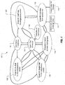
- FIG. 1 represents a schematic of reconfiguration management tool 101.
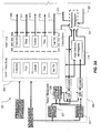
- Figures 2A and 2B represent a schematic of reconfigurable flight control system 201 which utilizes reconfiguration management tool 101.
- reconfiguration management tool 101 is configured for determining whether reconfiguration is necessary based upon at least a quantity of failures.
- a "no failure" event 103 requires no reconfiguration.
- failure may be at least an actuator failure or a sensor failure.
- other situations on the aircraft, other than an actuator or sensor failure may produce failure type scenarios which could trigger fault/fail detection and prompt reconfiguration of the flight control laws.
- a single failure event 105 will not trigger reconfiguration of flight control laws because a single failure event 105 should not degrade the flight control authority of the aircraft enough to warrant reconfiguration.
- the aircraft flight controls may be such that a single failure event 105 would in fact degrade the flight control authority enough to warrant reconfiguration.
- a risk factor calculation tool 121 is employed. Risk factor calculation tool 121 is discussed in further detail in connection with Figure 3 .
- a fault/failure detection tool 111 is used to detect sensor/actuator failure on the aircraft. Fault/Failure detection tool 111 may be incorporated into reconfiguration management tool 101, or segregated out of reconfiguration management tool, as shown in Figures 2A and 2B .
- a validation/verification tool 113 is also used to verify and backup the readings from fault/failure detection tool 111.
- a selection event 109 involves the operation of actuators, as desired from actuator look-up table 117.
- a symmetric control actuator arrangement 115 is may also be used to position a symmetric actuator in the same position as the failed actuator, which is discussed in further detail herein.
- Control gain set changes tool 119 in conjunction with a fader system, is uniquely employed to smooth the reconfiguration process, which is also discussed further herein.
- Reconfiguration management tool 101 is incorporated into reconfigurable flight control system 201.
- Fault/failure detection tool 111 is shown in relationship with other functions within reconfigurable flight control system 201.
- Control Laws 203 are used to provide flight control inputs to an actuator mixing/mapping matrix 207.
- Control laws 203 are a software-implemented tool for controlling actuators 401 and in turn, the flight of aircraft 403.
- Line 209 represents a power actuator command from control laws 203 to actuator mixing/mapping matrix 207 in order to produce an aircraft response 223.
- line 211 represents a pitch actuator command
- line 213 represents a roll actuator command
- line 215 represents a yaw actuator command
- line 217 represents a nacelle tilt actuator command.
- Line 219 represents an input from reconfiguration management tool 101 to actuator mixing/mapping matrix 207.
- Line 221 represents an input from actuator mixing/mapping matrix 207 to reconfiguration management tool 101.
- a sensor management tool 205 is configured to function with a Kalman filter 225 in conjunction with aircraft sensors 227 in order to allow for aircraft response to be measured by fault detection and diagnosis tool 111. Unique advantages of reconfigurable flight control system 201 will become more evident as further discussed herein. Sensor management tool 205 provides input to reconfiguration management tool 101 in order to smooth any transient conditions that may otherwise occur during reconfiguration.
- Figure 3 represents a graph 301 with risk factor 121 as a function of control power level 303, which is an empirical representation of a control authority of the aircraft.
- Risk factor 121 ( ⁇ ) is one of the key elements in determination whether reconfiguration is necessary. Risk factor ( ⁇ ) is based upon a handling qualities criteria 305 degrading from Level I to Level III based on ADS-33-D-PRF in helicopter mode or MIL-F-8785C in "airplane mode.”
- Calculation of risk factor 121 (p) is also based upon the control power of individual aircraft control axis. For example, in "airplane mode", an outside panel or flap of left wing will affect the flight control power in two axes. One axis is the lateral function and the other axis is the longitudinal function.
- risk factor 121 in lateral function is zero.
- Calculation of risk factor 121 is based upon individual axes of individual aircraft actuators.
- the maximum risk factor value of each axis is 1, which means that the axis in question is 100% not recoverable.
- the value of the risk factor 121 (p) starts increasing when the total control authority drops below Level I requirement.
- the control authority on each axis for any airspeed is preferably pre-calculated and treated as a knowledge base in the software program. Calculation of risk factor 121 is preferably restlessly running when reconfiguration management tool 101 is operating.
- FIG 4 is another graphical schematic of reconfigurable flight control system 201.
- Aircraft 403 has aircraft actuators 401 and aircraft sensors 103.
- aircraft 403 is represented as a quad tilt rotor 501.
- reconfigurable flight control system 201 may be fully implemented on aircraft 403 other than quad tilt rotor 501.
- Figure 20 illustrates a conventional tiltrotor 2001 which may employ reconfigurable flight control system 201.
- Other aircraft, including tandem rotorcraft, and even conventional rotorcraft with can benefit from the system of the present application.
- Quad tilt rotor 501 is depicted having a first and a second rotatable rotor 503a and 503b on a forward wing 507 and a third and a fourth rotatable rotor 505a and 505b on an aft wing 509. Additionally, quad tilt rotor 501 has a fuselage 511 and a landing gear 513.
- Figure 5 illustrates quad tilt rotor 501 in a "helicopter mode", in which rotors 503a, 503b, 505a, and 505b are directed approximately 90 degrees, or in an otherwise predominately vertical position.
- Figure 6 illustrates quad tilt rotor 501 in an "airplane mode", in which rotors 503a, 503b, 505a, and 505b are directed at approximately 0 degrees, or in an otherwise predominately horizontal position.
- Flight control features of quad tilt rotor 501 will be discussed further herein with regards to reconfigurable flight control system 201. It should be fully appreciated the system of the present application may be fully implemented on aircraft 403 other than quad tilt rotor 501.
- Aircraft sensors 227 are used in part to provide input to reconfiguration management tool 101 and fault/failure detection tool 111. Sensor values and statuses from aircraft sensors 227 also provide input to fault detection and diagnosis tool 105. Examples of aircraft sensors 227 include: global positions satellite systems (GPS), Inertial Navigations Systems (INS), gyros, attitude sensors, accelerometers, pressure sensors, air data computers (ADC), engine sensors, and rotor torque sensors, to name a few. Multiple sensors 227 may be used to provide redundancy in case a primary sensor 227 malfunctions. Though aircraft sensors 227 are depicted as a symbolic box in Figures 5 and 6 , it should be appreciated that sensors 227 are preferably deployed throughout aircraft 403 so as to best take measurements and provide data.
- GPS global positions satellite systems
- INS Inertial Navigations Systems
- gyros attitude sensors
- accelerometers pressure sensors
- ADC air data computers
- engine sensors and rotor torque sensors
- Aircraft actuators 401 will be described herein in the context of quad tilt rotor 501; however, it should be appreciated that the discussion herein regarding aircraft actuators 401 is applicable to an aircraft with features similar and different than that of quad tilt rotor 501, such as conventional tilt rotor aircraft 2001 shown in Figure 20 .
- aircraft actuators 401 should be interpreted generally to be any control surface, wing, engine, rotor, swashplate, flap, etc, that can contribute and dictate the flight path of aircraft 403.
- Each rotor 503a, 503b, 505a, and 505b has a swashplate (not shown) for producing a collective input, a lateral flapping input, and a forward/aft (F/A) flapping input.
- each rotor 503a, 503b, 505a, and 505b is capable of rotating between a "helicopter mode", wherein the rotors is generally vertical, and an "airplane mode", in which the rotors are generally horizontal.
- quad tilt rotor 501 has control surfaces, such as wings 507 and 509 and flaps 515a, 515b, 517a, and 517b.
- Figures 4A-4C represent a chart 401 listing of exemplary actuators 401 on quad tilt rotor 501. Actuators 401 that are non-moveable, such as the non-moveable portions of wings 507 and 509, are identified as N/A (non-actuatable) in Figures 7A-7C .
- "helicopter mode" of quad tilt rotor 501 is when quad tilt rotor 501 has its rotors 503a, 503b, 505a, and 505b at an angle between 80 and 90 degrees, while flying at airspeeds less than 80 knots, and a wing flap setting higher than 40 degrees.
- "airplane mode” of quad tilt rotor 501 is when quad tilt rotor 501 has its rotors 503a, 503b, 505a, and 505b at an angle of approximately 0 degrees while flying at airspeeds greater than 200 knots.
- "Conversion mode" of quad tilt rotor 501 is any flight mode between "helicopter mode” and "airplane mode”.
- Figure 8 illustrates a graph 801 showing the relationship between "helicopter mode", "airplane mode”, and “conversion mode” as a function of rotor tilt angle and airspeed.
- Figures 9-14 illustrate aerodynamic effects of operating certain actuators 401 of quad tilt rotor 501, while in "helicopter mode” and "airplane mode". It should first be noted that the quad tilt rotor 501 has the capability to differentiate collective power (DCP) so as to operate collective pitch the rotor blades of one rotor more or less than any other rotor so as to produce a desired reactionary force upon quad tilt rotor 501.
- DCP collective power
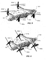
- Figure 9 illustrates a pitching up control axis of quad tilt rotor 501 while in "airplane mode.”
- Forward flaps 515a and 515b are actuated down, while aft flaps 517a and 517b are actuated up, thereby producing a pitching up control axis of quad tilt rotor 501 while in airplane mode.
- flaps 515a, 515b, 517a, and 517b are each comprised of multiple flaps, each individual flap being capable of being actuated individually or in conjunction with other flaps.
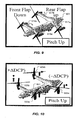
- Figure 10 illustrates a pitching up control axis of quad tilt rotor 501 employing differentiate collective power (DCP) while in "helicopter mode.”
- Swashplate actuators within rotors 503a, 503b, 505a, and 505b are actuated so as to produce a higher amount of thrust in the forward rotors 503a and 503b than within the aft rotors 505a and 505b, thereby producing a pitching up result of quad tilt rotor 501 while in "helicopter mode.”
- Figure 11 illustrates a rolling control axis of quad tilt rotor 501 while in "airplane mode.”
- Left flaps 515a and 517a are actuated up, while right flaps 515b and 517b are actuated down, thereby producing a left roll of quad tilt rotor 501 while in "airplane mode.”
- left flaps 515a and 517a can be actuated down, while right flaps 515b and 517b are actuated up, thereby producing a right roll of quad tilt rotor 501 while in "airplane mode.”
- Figure 12 illustrates a rolling control axis of quad tilt rotor 501 employing differentiate collective power (DCP) and lateral flapping, while in "helicopter mode.”
- Swashplate actuators within rotors 503a, 503b, 505a, and 505b are actuated so as to produce a higher amount of thrust in right rotors 503b and 505b than within left rotors 503a and 505a, thereby producing a roll left of quad tilt rotor 501 while in "helicopter mode.”
- swashplate actuators within right rotors 503b and 505b produce a cyclic lateral flapping upward
- swashplate actuators in left rotors 503a and 505a produce a cyclic lateral flapping downward.
- a roll to the right can be produced by performing the opposite functions that were used to achieve a roll to the left.
- Figure 13 illustrates a yawing control axis by employing differentiate collective power (DCP), while quad tilt rotor 501 is in "airplane mode.”
- Swashplate actuators within rotors 503a, 503b, 505a, and 505b are actuated so as to produce a higher amount of thrust in the right rotors 503b and 505b than within the left rotors 503a and 505a, thereby producing a yaw left of quad tilt rotor 501 while in "airplane mode.”
- swashplate actuators within rotors 503a, 503b, 505a, and 505b can be actuated so as to produce a higher amount of thrust in the left rotors 503a and 505a than within the right rotors 505b and 505b, thereby producing a yaw right of quad tilt rotor 501 while in "airplane mode.”
- Figure 14 illustrates a yawing control axis by employing cyclic lateral and longitudinal flapping, while quad tilt rotor 501 is in "helicopter mode.”
- Swashplate actuators within the right rotors 503b and 505b produce a cyclic lateral flapping upward and a forward longitudinal flapping
- swashplate actuators in left rotors 503a and 505a produce a cyclic lateral flapping downward and a reverse longitudinal flapping in order to produce a yaw to the left while quad tilt rotor 501 is in "helicopter mode.”
- a yaw to the right can be produced by performing the opposite functions that were used to achieve a yaw to the left.
- differential nacelle tilt angles for controlling yaw moments is reserved as a redundant/reserve control in actuator mixing/mapping matrix 207 of reconfigurable flight control system 201.
- primary controls of quad tilt rotor 501 in "airplane mode” are summarized in chart 1601 of Figure 16 . Forward speed in "airplane mode” is controlled by a throttle setting. It should also be noted that RPM of the rotors is reduced from approximately 397 to 333 before the rotors reach airplane mode position.
- Quad tilt rotor 501 Redundancies in the control axis (pitch, roll, and yaw) of quad tilt rotor 501 in helicopter mode allow for greater variety in reconfiguration of flight control laws 203.
- the variety of usable flight control laws can better appreciated when comparing quad tilt rotor 501 to the flight control system for general rotorcraft.
- quad tilt rotor 501 has rotors 503a, 503b, 505a, and 505b with cyclic capabilities, then quad tilt rotor 501 can fly using typical helicopter flight control laws when in low airspeed "helicopter mode.”
- Quad tilt rotor 501 can also use helicopter flight control laws indicative of a tandem rotorcraft.
- a typical tandem rotorcraft has a fuselage with a front rotor and a rear rotor, both rotors being mounted to the fuselage.
- the rotors on a tandem rotorcraft are considered to be of the same power set in the flight control laws.
- Quad tilt rotor 501 can also use helicopter flight control laws indicative of a conventional tiltrotor aircraft, such as conventional tiltrotor aircraft 2001 having two articulated rotors 2003a and 2003b on each end of a wing 2005, as shown in Figure 20 .
- the helicopter mode flight control laws can be indicative of a conventional helicopter, a tandem rotorcraft, a conventional tiltrotor aircraft, or any combination of the three.
- Reconfigurable flight control system 201 of the present application utilizes a combination of conventional tiltrotor flight control laws and tandem rotorcraft flight control laws for flight control laws 203.
- Flight control laws 203 utilize control actuator contribution from one set of primary main control surfaces as a dominator and reserves redundant or secondary main control surfaces for balance and reconfiguration. If the primary or dominator main control fails, flight control laws 203 is automatically reconfigured by reconfiguration management tool 201 so as to employ the use of redundant control actuators.
- Redundancies in the control axis (pitch, roll, and yaw) of quad tilt rotor 501 in "airplane mode" allow for greater variety in reconfiguration of flight control laws. For example, because yaw control in airplane mode is controlled by DCP of left and right rotors, then yaw can be achieve by a thrust difference between the left and right sides. Since there are four rotors, there are four redundancies in regard to controlling quad tilt rotor 109 in the yaw control axis. Pitch control (or elevation) of quad tilt rotor 501 can be obtained by the difference between front wing flaps 515a and 515b, and aft wing flaps 517a and 517b.
- each set of flaps 515a, 515b, 517a, and 517b are actually comprised of three or more small panels, each small panel being independently subject to actuation.
- pitch axis control of quad tilt rotor 501 in "airplane mode.”
- Roll control of quad tilt rotor 501 can be obtained by the difference between left wing flaps 515a and 517a, and right wing flaps 515b and 517b.
- Another method is to fix the left flaps 515a and 217a, while actuating the right wing flaps 515b and 517b.
- each set of flaps 515a, 515b, 517a, and 517b are actually comprised of three or more small panels, each small panel being independently subject to actuation.
- Such uncertainties typically include aerodynamics with more than five sources, such as: 1) fuselage/empennage/anti-torque/stabilizer interactions, 2) control actuator delays/couplings/fault or failure, 3) sensor management error/fault or battle damage, 4) estimation of incompressible drag (I/D) coefficient, and,5) outside wind effect.
- Kalman filter 225 within sensor management tool 205 is utilized so that a single sensor failure in the aircraft will not cause any flight quality difference.
- Kalman filter provides only a slight downgrade in flight performance if multiple sensors were to fail.
- One objective in using passive actuator failure protection through the use of Kalman filter 225 is to reduce sensitivities from uncertainties.
- Another objective is to associate Kalman filter 225 with minimum available sensors in order to estimate full state variables so that sensor failure mode can be protected. In such a manner, Kalman filter 225 interprets data from flight control sensors on the aircraft.
- Kalman filter 225 and control laws 203 consider fundamental sources of 1) aerodynamics of the aircraft, 2) flight mechanics of the aircraft, 3) control power coefficient changes due to aerodynamics, 4) center of gravity shifting, 5) wind disturbances, and 6) aerodynamic ground effect and building effect (from urban flight).
- Robust control laws 203 and estimations are employed to achieve certain objectives.
- a first objective is that robust control laws and estimations automatically compute all phase margins and gain margins on any speeds to help consolidate the control laws.
- a second objective is to ensure the efficiency of control input during the entire flight envelope using a minimum energy function/maximum performance requirement.
- a third objective is to help reduction of the disturbance affections from aerodynamic interaction by aircraft structures and controls.
- a fourth objective is to reduce the noise level of the aircraft by ensuring the control amplitudes are small during maneuvers.
- a fifth objective is to allow the pilot to stabilize the aircraft in the event of multiple sensors failing.
- a sixth objective is for the stabilization of SCAS control mode (inner loop), which is inherently not stable.
- a seventh objective is to make the aircraft as robust as possible so that any sudden wind changes will not affect flight characteristics.
- An eighth objective is to prevent the need for logic switches in the cockpit in order to avoid confusion and simplify flight switch logic design.
- a ninth objective is to prevent changes in aircraft gross weight and center of gravity from affecting the flight characteristics.
- One purpose of the system of the present application is to robustly construct reconfiguration control system 201 so as to minimize negative results of reconfiguration during a maneuver of quad tilt rotor 501.
- Undesirable transient conditions may occur when the aircraft actuators 401 are repositioned during reconfiguration. Transient conditions may be harmful to aircraft 403 and to occupants of aircraft 403.
- Reconfigurable control system 201 acts to limit the occurrence of transients, which are harmful rapid changes in actuators 401 resulting sudden flight disturbances. Transients may induce the saturation of amplitude and/or rate limits in aircraft actuators 401 as well as damage aircraft system components. As such, there exists considerable motivation to limit and manage an occurrence of a transient situation.
- actuators 401 have multiple input/output systems. Identifiable conditions of actuators 401 are: 1) a fault free period, 2) a transient period during reconfiguration, 3) reconfiguration during a maneuver mode, and 4) steady state flight after reconfiguration.
- an actuator 401 fails such as a flap 515a
- actuator 401 can either remain at its failed position or retract back to its neutral position.
- Control position sensors 227 are configured to detect whether the actuator 401 was able to retract back to its neutral position or whether actuator 401 remained at its failed position.
- fader 1803 is used to reduce harmful transients during reconfiguration.
- Input cross-fading methods involve introducing fade block installation in front of the input side; as such, when reconfiguration starts, the input from feedback will be slowly incremented in order to avoid higher amplitude feedback from the input side.
- Output cross-fading methods involves introducing fade block installation on the output side of the actuator; as such, when reconfiguration starts, the output signal will start from its original value and slowly convert failed actuators to new reconfiguration actuators.
- Quad tilt rotor 501 has symmetric actuators 401 between the left and right sides, as well symmetric actuators 401 on forward and aft portions of the aircraft.
- symmetric control surface arrangement is hereby presented.
- a primary focus of symmetric control surface arrangement is to detect the failed actuator and actuate a symmetrically opposite non-failed actuator in the same position as the failed actuator in order to provide aerodynamic stability to the quad tilt rotor 501.
- This seamless reconfiguration of actuators 401 can be described as a "trim” and "sync" process.
- the "trimming" of the actuators is the symmetric balancing of the positions of the actuators 401 together for lateral and longitudinal control balancing.
- the “syncing” of the actuators is the locking of the actuators 401 in their “trimmed” positions.
- This symmetric control surface arrangement is preferably located within reconfiguration management tool 101, shown in Figure 1 . It should be appreciated that symmetric control surface arrangement acts to limit and manage an occurrence of a transient situation, as well as provide an efficient means for reconfiguring control laws 203.
- Control actuator mixing/mapping matrix 207 can take several forms.
- One objective of control actuator mixing/mapping matrix 207 is to safely transfer authority from any failed actuators 401 to back-up actuators 401 during reconfiguring while reducing the possibility of a large reconfiguration transient.
- schematic 2001 illustrates how output fader 1803 is employed to achieve reconfiguration transient reduction.
- mapping rules When it has been determined that reconfiguration is necessary, then an account of the healthy actuators is necessary. Management of these healthy actuators that can be employed for reconfiguration is managed by a set of mapping rules. These mapping rules then become logical management software design so as to determine a set of mapping routes that can be used when a set of particular actuator or component failure occurs.
- control actuator mixing/mapping matrix 207 provides that capability to first mix the usage of actuators.
- An example of mixing actuators would be to control lateral axis of the aircraft using 80% DCP and 20% flaps.
- the mapping function within control actuator mixing/mapping matrix 207 provides the capability to continuously re-map or change the percentages of the actuators being used, such as using 85% DCP and 15% flaps in order to provide a lateral control axis for the aircraft.
- control actuator mixing/mapping matrix 207 provides collective mixing, pitch mixing, lateral mixing, yaw mixing, and nacelle (rotor) tilt mixing.
- Control actuator mixing/mapping matrix 207 also uses a fader in the mixing process in order to smooth transients, or any destabilization in flight control due to a jump in actuator reconfiguration.
- Predetermination of this triggering event is achieved by an infinity state flow technique to switch the necessary protection for reconfiguration design. Timing, delay, and reconfirming the event can all be included in this infinity state flow logic.
- a selection of an appropriate new and healthy actuator 401 occurs when each triggering event occurs. Pre-calculation of the appropriate healthy actuator 401 for each triggering event shall be carefully predetermined. It shall be insured that after transforming to new actuator set, the performance of aircraft 501 shall maintain reliability and safety in flight. The control power authority related to risk factor or degraded ratio is employed to minimize the risk of reconfiguring the flight controls.
- control actuator mixing/mapping matrix 207 is used to make reconfiguration successful and safe. Each step, from integration of the trigger event to the mapping of the new actuator set, is interpreted with caution. At the final mapping step, the healthy actuators will remain unchanged. The new actuator movement will preferably start from its current trim point and all actuators will reach there desired position, either laterally or longitudinally.
- the primary objective for introducing redundancy and fault tolerance is to increase the reliability and safety of a controlled system.
- Safety is the ability of a system to keep from causing danger to human life, equipment or environment.
- Reliability is the ability of a system or component to perform a required function correctly over a given period of time under a given set of fault conditions.
- Control re-configurability assesses the system ability to allow performance restoration in the presence of faults.
- the system of the present application provides many significant advantages over non-reconfigurable flight control system. Occurrence of a failure situation on aircraft is potentially catastrophic; however, a reconfigurable flight control system acts to reduce a pilot's burdens by reducing the pilot's responsibilities while allowing the pilot to maintain their flight skill so as to bring the aircraft home safely. This functionality acts to save lives and aircraft.
- the system of the present application provides significant advantages, including: (1) providing individual axis flight control technology; (2) using a combination of tandem and conventional tilt-rotor flight control laws; (3) using gain scheduling to achieve Handling Qualities Level I; (4) providing a Kalman filter for protection against sensor failure; and (5) providing robust control to protect against uncertainties; (6) providing fault and failure detection with validation and verification; (7) providing fader function in order to make input/output switching smoother; (8) reduction of transient occurrence during reconfiguration; (9) development of symmetric control surface arrangement technique; (10) providing control authority in risk factor design; (11) providing smooth performance upon sensor or actuator failure; (12) providing multi-layer table look-up for reconfiguration with gain-rescheduling; and (13) integration of reconfigurable flight control laws of each control axis.
Landscapes
- Engineering & Computer Science (AREA)
- Physics & Mathematics (AREA)
- General Physics & Mathematics (AREA)
- Automation & Control Theory (AREA)
- Aviation & Aerospace Engineering (AREA)
- Radar, Positioning & Navigation (AREA)
- Remote Sensing (AREA)
- Chemical & Material Sciences (AREA)
- Chemical Kinetics & Catalysis (AREA)
- Mechanical Engineering (AREA)
- Traffic Control Systems (AREA)
- Feedback Control In General (AREA)
Description
- The system of the present application relates in general to the field of flight control for aircraft. In particular, the system relates to apparatus and methods for using reconfigurable flight control laws to operate an aircraft during sensor and actuator failure.
-
US 3,665,173 discloses a computer system of the standby redundancy type including three active logic modules and at least one spare module, characterized by the provision of triple modular redundancy means for correcting and locating the failure of a first one of said active logic modules, in combination with sparing means for reconfiguring the system to by-pass the faulty module and to substitute the spare module therefor. The provision of means for reintroducing the first module into the system upon the detection of failure of another active module is also disclosed. -
US 4,260,942 discloses an apparatus and a related method for detecting failures of control elements, such as skewed-axis reaction wheels with closed-loop speed control, used in satellite attitude control systems, and for compensating for such failures and thereby maintaining continuity of operation. The apparatus includes a wheel loop model for simulating operation of each of the reaction wheels and speed control loops in the satellite, and for deriving an estimated wheel speed from a command speed for each wheel. By comparing the estimated speed of each wheel with the corresponding actual or observed speed, the apparatus determines whether a failure was occurred in the wheel, or in its control loop. Upon detection of such a failure, the apparatus disconnects driving power from the failed wheel, modifies the corresponding wheel loop model to reflect disconnection of power, and reconfigures a distribution matrix in such a manner that a set of desired momentum commands with respect to the vehicle axes is properly redistributed among the remaining reaction wheels. Compensation is also made for the momentum contributions of failed wheels that continue to spin after being powered down. - The novel features believed characteristic of the system of the present application are set forth in the appended claims. However, the system itself, as well as, a preferred mode of use, and further objectives and advantages thereof, will best be understood by reference to the hollowing detailed description when read in conjunction with the accompanying drawings, wherein:
-
Figure 1 is a reconfiguration management tool according to the preferred embodiment of the present application; -
Figures 2A and2B represent a continuous schematic of reconfigurable flight control system according the preferred embodiment of the present application; -
Figure 3 is a graphical representation of risk factor versus control power level; -
Figure 4 is a schematic representation of reconfigurable flight control system; -
Figure 5 is a perspective view of the quad tilt rotor aircraft, while in airplane mode, having the reconfigurable flight control system according the preferred embodiment of the present application; -
Figure 6 is a perspective view of the quad tilt rotor aircraft, while in airplane mode, having the reconfigurable flight control system according the preferred embodiment of the present application; -
Figures 7A-7C represent a listing of exemplary actuators on the quad tilt rotor; -
Figure 8 is graph showing the relationship between helicopter mode, airplane mode, and conversion mode as a function of rotor tilt angle and airspeed; -
Figure 9 is a perspective view of the quad tilt rotor aircraft, while in airplane mode, with a pitch up control axis; -
Figure 10 is a perspective view of the quad tilt rotor aircraft, while in helicopter mode, with a pitch up control axis; -
Figure 11 is a perspective view of the quad tilt rotor aircraft, while in airplane mode, with a roll left control axis; -
Figure 12 is a perspective view of the quad tilt rotor aircraft, while in helicopter mode, with a roll left control axis; -
Figure 13 is a perspective view of the quad tilt rotor aircraft, while in airplane mode, with a yaw left control axis; -
Figure 14 is a perspective view of the quad tilt rotor aircraft, while in helicopter mode, with a yaw left control axis; -
Figure 15 is chart summarizing the primary controls of the quad tilt rotor while in helicopter mode; -
Figure 16 is chart summarizing the primary controls of the quad tilt rotor while in airplane mode; -
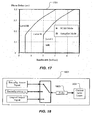
Figure 17 is a graphical representation of SCAS mode and autopilot (Automatic control) mode as a function of bandwidth and phase delay; -
Figure 18 is a schematic representation of the use of a fader in conjunction with flight control laws; -
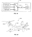
Figure 19 is a schematic representation of the use of a fader in conjunction with a mixing/mapping matrix; and -
Figure 20 is a perspective view of a conventional tiltrotor according to an alternative embodiment. - While the system of the present application is susceptible to various modifications and alternative forms, specific embodiments thereof have been shown by way of example in the drawings and are herein described in detail. It should be understood, however, that the description herein of specific embodiments is not intended to limit the system to the particular forms disclosed, but on the contrary, the intention is to cover all modifications, equivalents, and alternatives falling within the scope of the present application as defined by the appended claims.
- In accordance with the invention as defined by the appended claims there is provided a reconfigurable flight control system, an aircraft and a method of automatically reconfiguring flight control of an aircraft.
- Illustrative embodiments of the system of the present application are described below. In the interest of clarity, not all features of an actual implementation are described in this specification. It will of course be appreciated that in the development of any such actual embodiment, numerous implementation-specific decisions must be made to achieve the developer's specific goals, such as compliance with system-related and business-related constraints, which will vary from one implementation to another. Moreover, it will be appreciated that such a development effort might be complex and time-consuming but would nevertheless be a routine undertaking for those of ordinary skill in the art having the benefit of this disclosure.
- In the specification, reference may be made to the spatial relationships between various components and to the spatial orientation of various aspects of components as the devices are depicted in the attached drawings. However, as will be recognized by those skilled in the art after a complete reading of the present application, the devices, members, apparatuses, etc. described herein may be positioned in any desired orientation. Thus, the use of terms such as "above," "below," "upper," "lower," or other like terms to describe a spatial relationship between various components or to describe the spatial orientation of aspects of such components should be understood to describe a relative relationship between the components or a spatial orientation of aspects of such components, respectively, as the device described herein may be oriented in any desired direction.
- An aircraft during flight is susceptible to a variety of failure scenarios that can potentially be life threatening for the crew and passengers on board, as well as destructive to the aircraft itself. Examples of failure scenarios are: engine failure, control actuator failure, control surface damage from in flight collision with an object, battle damage sustained to a military aircraft, and sensor failure, to name a few. Because most modern day aircraft are controlled using a computer system with flight control laws, a failure scenario mentioned above can quickly result in catastrophic situation do to the flight control laws not being reconfigurable in such a scenario. As a simplified example, if a multi-engine aircraft were to lose an engine during flight, and if the flight control laws were not reconfigurable, then the aircraft may not be able to survive the incident even though the aircraft potentially could have used alternate aircraft actuators to compensate for the loss off an engine and therefore maintain control of the aircraft. Reconfigurable flight control laws are desirable on all aircraft; however, aircraft having multiple and/or redundant flight control actuators are more attractive for implementation of a reconfigurable flight control system. It should be appreciated that the reconfigurable flight control system disclosed herein can be implemented on a variety of aircraft.
- One aspect of the present application is the use of a
reconfiguration management tool 101 in order to dictate reconfiguration of flight controls law in a reconfigurableflight control system 201.Figure 1 represents a schematic ofreconfiguration management tool 101.Figures 2A and2B represent a schematic of reconfigurableflight control system 201 which utilizesreconfiguration management tool 101. - Referring to
Figure 1 ,reconfiguration management tool 101 is configured for determining whether reconfiguration is necessary based upon at least a quantity of failures. In the preferred embodiment, a "no failure"event 103 requires no reconfiguration. It should be appreciated that the term failure may be at least an actuator failure or a sensor failure. In addition, other situations on the aircraft, other than an actuator or sensor failure, may produce failure type scenarios which could trigger fault/fail detection and prompt reconfiguration of the flight control laws. In the preferred embodiment, asingle failure event 105 will not trigger reconfiguration of flight control laws because asingle failure event 105 should not degrade the flight control authority of the aircraft enough to warrant reconfiguration. However, in some embodiments the aircraft flight controls may be such that asingle failure event 105 would in fact degrade the flight control authority enough to warrant reconfiguration. In order for the system to automatically decide whether reconfiguration is necessary, a riskfactor calculation tool 121 is employed. Riskfactor calculation tool 121 is discussed in further detail in connection withFigure 3 . It should be appreciated that a fault/failure detection tool 111 is used to detect sensor/actuator failure on the aircraft. Fault/Failure detection tool 111 may be incorporated intoreconfiguration management tool 101, or segregated out of reconfiguration management tool, as shown inFigures 2A and2B . A validation/verification tool 113 is also used to verify and backup the readings from fault/failure detection tool 111. In the preferred embodiment, detection of amultiple failure event 107 by fault/failure detection tool 111 warrants reconfiguration of flight controls in order to regain control authority. Aselection event 109 involves the operation of actuators, as desired from actuator look-up table 117. A symmetriccontrol actuator arrangement 115 is may also be used to position a symmetric actuator in the same position as the failed actuator, which is discussed in further detail herein. Control gain setchanges tool 119, in conjunction with a fader system, is uniquely employed to smooth the reconfiguration process, which is also discussed further herein. - Now referring to
Figures 2A-2B , illustrated is a continuous schematic of reconfigurableflight control system 201.Reconfiguration management tool 101 is incorporated into reconfigurableflight control system 201. Fault/failure detection tool 111 is shown in relationship with other functions within reconfigurableflight control system 201.Control Laws 203 are used to provide flight control inputs to an actuator mixing/mapping matrix 207.Control laws 203 are a software-implemented tool for controllingactuators 401 and in turn, the flight ofaircraft 403.Line 209 represents a power actuator command fromcontrol laws 203 to actuator mixing/mapping matrix 207 in order to produce anaircraft response 223. Similarly,line 211 represents a pitch actuator command,line 213 represents a roll actuator command,line 215 represents a yaw actuator command, andline 217 represents a nacelle tilt actuator command.Line 219 represents an input fromreconfiguration management tool 101 to actuator mixing/mapping matrix 207.Line 221 represents an input from actuator mixing/mapping matrix 207 toreconfiguration management tool 101. Asensor management tool 205 is configured to function with aKalman filter 225 in conjunction withaircraft sensors 227 in order to allow for aircraft response to be measured by fault detection anddiagnosis tool 111. Unique advantages of reconfigurableflight control system 201 will become more evident as further discussed herein.Sensor management tool 205 provides input toreconfiguration management tool 101 in order to smooth any transient conditions that may otherwise occur during reconfiguration. -
Figure 3 represents agraph 301 withrisk factor 121 as a function ofcontrol power level 303, which is an empirical representation of a control authority of the aircraft. Risk factor 121 (ρ) is one of the key elements in determination whether reconfiguration is necessary. Risk factor (ρ) is based upon ahandling qualities criteria 305 degrading from Level I to Level III based on ADS-33-D-PRF in helicopter mode or MIL-F-8785C in "airplane mode." Calculation of risk factor 121 (p) is also based upon the control power of individual aircraft control axis. For example, in "airplane mode", an outside panel or flap of left wing will affect the flight control power in two axes. One axis is the lateral function and the other axis is the longitudinal function. During the control power calculation, this panel will not drop the system out of Level I in lateral function in any airspeed mode. Therefore,risk factor 121 in lateral function is zero. Similarly, therisk factor 121 for each axis is determined and thetotal risk factor 121 can be represented by the following equation:
- Calculation of
risk factor 121 is based upon individual axes of individual aircraft actuators. The maximum risk factor value of each axis is 1, which means that the axis in question is 100% not recoverable. Based on individual actuators contributing to the total control authority of the axis, the value of the risk factor 121 (p) starts increasing when the total control authority drops below Level I requirement. The control authority on each axis for any airspeed is preferably pre-calculated and treated as a knowledge base in the software program. Calculation ofrisk factor 121 is preferably restlessly running whenreconfiguration management tool 101 is operating. - Referring to
Figure 4 , which is another graphical schematic of reconfigurableflight control system 201.Aircraft 403 hasaircraft actuators 401 andaircraft sensors 103. For purposes of providing an exemplary application of reconfigurableflight control system 201,aircraft 403 is represented as aquad tilt rotor 501. It should be fully appreciated that reconfigurableflight control system 201 may be fully implemented onaircraft 403 other thanquad tilt rotor 501. For example,Figure 20 illustrates aconventional tiltrotor 2001 which may employ reconfigurableflight control system 201. Other aircraft, including tandem rotorcraft, and even conventional rotorcraft with can benefit from the system of the present application. - Referring now to
Figures 5 and 6 ,Quad tilt rotor 501 is depicted having a first and a secondrotatable rotor forward wing 507 and a third and a fourthrotatable rotor aft wing 509. Additionally,quad tilt rotor 501 has afuselage 511 and alanding gear 513.Figure 5 illustratesquad tilt rotor 501 in a "helicopter mode", in whichrotors Figure 6 illustratesquad tilt rotor 501 in an "airplane mode", in whichrotors quad tilt rotor 501 will be discussed further herein with regards to reconfigurableflight control system 201. It should be fully appreciated the system of the present application may be fully implemented onaircraft 403 other thanquad tilt rotor 501. -
Aircraft sensors 227 are used in part to provide input toreconfiguration management tool 101 and fault/failure detection tool 111. Sensor values and statuses fromaircraft sensors 227 also provide input to fault detection anddiagnosis tool 105. Examples ofaircraft sensors 227 include: global positions satellite systems (GPS), Inertial Navigations Systems (INS), gyros, attitude sensors, accelerometers, pressure sensors, air data computers (ADC), engine sensors, and rotor torque sensors, to name a few.Multiple sensors 227 may be used to provide redundancy in case aprimary sensor 227 malfunctions. Thoughaircraft sensors 227 are depicted as a symbolic box inFigures 5 and 6 , it should be appreciated thatsensors 227 are preferably deployed throughoutaircraft 403 so as to best take measurements and provide data. -
Aircraft actuators 401 will be described herein in the context ofquad tilt rotor 501; however, it should be appreciated that the discussion herein regardingaircraft actuators 401 is applicable to an aircraft with features similar and different than that ofquad tilt rotor 501, such as conventionaltilt rotor aircraft 2001 shown inFigure 20 . For purposes of this discussion,aircraft actuators 401 should be interpreted generally to be any control surface, wing, engine, rotor, swashplate, flap, etc, that can contribute and dictate the flight path ofaircraft 403. Eachrotor rotor quad tilt rotor 501 has control surfaces, such aswings flaps Figures 4A-4C represent achart 401 listing ofexemplary actuators 401 onquad tilt rotor 501.Actuators 401 that are non-moveable, such as the non-moveable portions ofwings Figures 7A-7C . - In general, "helicopter mode" of
quad tilt rotor 501 is whenquad tilt rotor 501 has itsrotors quad tilt rotor 501 is whenquad tilt rotor 501 has itsrotors quad tilt rotor 501 is any flight mode between "helicopter mode" and "airplane mode".Figure 8 illustrates agraph 801 showing the relationship between "helicopter mode", "airplane mode", and "conversion mode" as a function of rotor tilt angle and airspeed. -
Figures 9-14 illustrate aerodynamic effects of operatingcertain actuators 401 ofquad tilt rotor 501, while in "helicopter mode" and "airplane mode". It should first be noted that thequad tilt rotor 501 has the capability to differentiate collective power (DCP) so as to operate collective pitch the rotor blades of one rotor more or less than any other rotor so as to produce a desired reactionary force uponquad tilt rotor 501. -
Figure 9 illustrates a pitching up control axis ofquad tilt rotor 501 while in "airplane mode." Forward flaps 515a and 515b are actuated down, whileaft flaps quad tilt rotor 501 while in airplane mode. It should be appreciated thatflaps -
Figure 10 illustrates a pitching up control axis ofquad tilt rotor 501 employing differentiate collective power (DCP) while in "helicopter mode." Swashplate actuators , within rotors 503a, 503b, 505a, and 505b are actuated so as to produce a higher amount of thrust in theforward rotors aft rotors quad tilt rotor 501 while in "helicopter mode." -
Figure 11 illustrates a rolling control axis ofquad tilt rotor 501 while in "airplane mode."Left flaps right flaps quad tilt rotor 501 while in "airplane mode." Similarly, leftflaps right flaps quad tilt rotor 501 while in "airplane mode." -
Figure 12 illustrates a rolling control axis ofquad tilt rotor 501 employing differentiate collective power (DCP) and lateral flapping, while in "helicopter mode." Swashplate actuators withinrotors right rotors left rotors quad tilt rotor 501 while in "helicopter mode." In order to supplement the roll left produced by employing DCP, swashplate actuators withinright rotors left rotors -
Figure 13 illustrates a yawing control axis by employing differentiate collective power (DCP), whilequad tilt rotor 501 is in "airplane mode." Swashplate actuators withinrotors right rotors left rotors quad tilt rotor 501 while in "airplane mode." Similarly, swashplate actuators withinrotors left rotors right rotors quad tilt rotor 501 while in "airplane mode." -
Figure 14 illustrates a yawing control axis by employing cyclic lateral and longitudinal flapping, whilequad tilt rotor 501 is in "helicopter mode." Swashplate actuators within theright rotors left rotors quad tilt rotor 501 is in "helicopter mode." Similarly, a yaw to the right can be produced by performing the opposite functions that were used to achieve a yaw to the left. - Primary controls of
quad tilt rotor 501 in "helicopter mode" are summarized in achart 1501 inFigure 15 . With the exception of vertical control from rotor collective responses, all other three axis (pitch, roll, and yaw) having redundancy from either DCP or rotor flapping of F/A (forward/aft) axis or lateral axis. It should be noted that it is desired to use differential nacelle tilt angles to offset yawing moments in the event of a failure condition. It is not desirable to use differential nacelle tilt angle as a primary control because the response time of rotating the nacelles is too slow. As such, the use of differential nacelle tilt angles for controlling yaw moments is reserved as a redundant/reserve control in actuator mixing/mapping matrix 207 of reconfigurableflight control system 201. Similarly, primary controls ofquad tilt rotor 501 in "airplane mode" are summarized inchart 1601 ofFigure 16 . Forward speed in "airplane mode" is controlled by a throttle setting. It should also be noted that RPM of the rotors is reduced from approximately 397 to 333 before the rotors reach airplane mode position. - Redundancies in the control axis (pitch, roll, and yaw) of
quad tilt rotor 501 in helicopter mode allow for greater variety in reconfiguration offlight control laws 203. The variety of usable flight control laws can better appreciated when comparingquad tilt rotor 501 to the flight control system for general rotorcraft. In regards to flight control laws for helicopter mode, becausequad tilt rotor 501 hasrotors quad tilt rotor 501 can fly using typical helicopter flight control laws when in low airspeed "helicopter mode."Quad tilt rotor 501 can also use helicopter flight control laws indicative of a tandem rotorcraft. A typical tandem rotorcraft has a fuselage with a front rotor and a rear rotor, both rotors being mounted to the fuselage. The rotors on a tandem rotorcraft are considered to be of the same power set in the flight control laws.Quad tilt rotor 501 can also use helicopter flight control laws indicative of a conventional tiltrotor aircraft, such asconventional tiltrotor aircraft 2001 having two articulatedrotors wing 2005, as shown inFigure 20 . As such, the helicopter mode flight control laws can be indicative of a conventional helicopter, a tandem rotorcraft, a conventional tiltrotor aircraft, or any combination of the three. Additionally, the aforementioned helicopter flight control laws can be used during the transition mode between "helicopter mode" and "airplane mode." Reconfigurableflight control system 201 of the present application utilizes a combination of conventional tiltrotor flight control laws and tandem rotorcraft flight control laws forflight control laws 203.Flight control laws 203 utilize control actuator contribution from one set of primary main control surfaces as a dominator and reserves redundant or secondary main control surfaces for balance and reconfiguration. If the primary or dominator main control fails,flight control laws 203 is automatically reconfigured byreconfiguration management tool 201 so as to employ the use of redundant control actuators. - Redundancies in the control axis (pitch, roll, and yaw) of
quad tilt rotor 501 in "airplane mode" allow for greater variety in reconfiguration of flight control laws. For example, because yaw control in airplane mode is controlled by DCP of left and right rotors, then yaw can be achieve by a thrust difference between the left and right sides. Since there are four rotors, there are four redundancies in regard to controllingquad tilt rotor 109 in the yaw control axis. Pitch control (or elevation) ofquad tilt rotor 501 can be obtained by the difference betweenfront wing flaps aft wing flaps front wing flaps aft wing flaps front wing flaps aft wing flaps wing flaps flaps quad tilt rotor 501 in "airplane mode." Roll control ofquad tilt rotor 501 can be obtained by the difference betweenleft wing flaps left flaps 515a and 217a, while actuating the right wing flaps 515b and 517b. Similarly, another method is to fix the right wing flaps 515b and 517b, while actuating theleft wing flaps flaps quad tilt rotor 501 in "airplane mode." In order for reconfigurableflight control system 201 to be robust, it must take advantage all of the available aforementioned redundancies, as well as take into account all types of possible failures. - Robustness of is achieved in reconfigurable
flight control system 201 in part by consideration of a multitude of uncertainties within the aircraft model. Such uncertainties typically include aerodynamics with more than five sources, such as: 1) fuselage/empennage/anti-torque/stabilizer interactions, 2) control actuator delays/couplings/fault or failure, 3) sensor management error/fault or battle damage, 4) estimation of incompressible drag (I/D) coefficient, and,5) outside wind effect. - With regards to sensor failure protection and disturbance attenuation, a
Kalman filter 225 withinsensor management tool 205 is utilized so that a single sensor failure in the aircraft will not cause any flight quality difference. In addition, Kalman filter provides only a slight downgrade in flight performance if multiple sensors were to fail. One objective in using passive actuator failure protection through the use ofKalman filter 225 is to reduce sensitivities from uncertainties. Another objective is to associateKalman filter 225 with minimum available sensors in order to estimate full state variables so that sensor failure mode can be protected. In such a manner,Kalman filter 225 interprets data from flight control sensors on the aircraft.Kalman filter 225 andcontrol laws 203 consider fundamental sources of 1) aerodynamics of the aircraft, 2) flight mechanics of the aircraft, 3) control power coefficient changes due to aerodynamics, 4) center of gravity shifting, 5) wind disturbances, and 6) aerodynamic ground effect and building effect (from urban flight).Robust control laws 203 and estimations are employed to achieve certain objectives. A first objective is that robust control laws and estimations automatically compute all phase margins and gain margins on any speeds to help consolidate the control laws. A second objective is to ensure the efficiency of control input during the entire flight envelope using a minimum energy function/maximum performance requirement. A third objective is to help reduction of the disturbance affections from aerodynamic interaction by aircraft structures and controls. A fourth objective is to reduce the noise level of the aircraft by ensuring the control amplitudes are small during maneuvers. A fifth objective is to allow the pilot to stabilize the aircraft in the event of multiple sensors failing. A sixth objective is for the stabilization of SCAS control mode (inner loop), which is inherently not stable. A seventh objective is to make the aircraft as robust as possible so that any sudden wind changes will not affect flight characteristics. An eighth objective is to prevent the need for logic switches in the cockpit in order to avoid confusion and simplify flight switch logic design. A ninth objective is to prevent changes in aircraft gross weight and center of gravity from affecting the flight characteristics. - One purpose of the system of the present application is to robustly construct
reconfiguration control system 201 so as to minimize negative results of reconfiguration during a maneuver ofquad tilt rotor 501. Undesirable transient conditions may occur when theaircraft actuators 401 are repositioned during reconfiguration. Transient conditions may be harmful toaircraft 403 and to occupants ofaircraft 403.Reconfigurable control system 201 acts to limit the occurrence of transients, which are harmful rapid changes inactuators 401 resulting sudden flight disturbances. Transients may induce the saturation of amplitude and/or rate limits inaircraft actuators 401 as well as damage aircraft system components. As such, there exists considerable motivation to limit and manage an occurrence of a transient situation. One challenge in management of transient situations is in the management of actuators for different conditions whenactuators 401 have multiple input/output systems. Identifiable conditions ofactuators 401 are: 1) a fault free period, 2) a transient period during reconfiguration, 3) reconfiguration during a maneuver mode, and 4) steady state flight after reconfiguration. When anactuator 401 fails, such as aflap 515a,actuator 401 can either remain at its failed position or retract back to its neutral position.Control position sensors 227 are configured to detect whether theactuator 401 was able to retract back to its neutral position or whetheractuator 401 remained at its failed position. - Referring to
Figure 18 , in schematic 1801, input and output fading methods are represented asfader 1803. As discussed herein,fader 1803 is used to reduce harmful transients during reconfiguration. Input cross-fading methods involve introducing fade block installation in front of the input side; as such, when reconfiguration starts, the input from feedback will be slowly incremented in order to avoid higher amplitude feedback from the input side. Output cross-fading methods involves introducing fade block installation on the output side of the actuator; as such, when reconfiguration starts, the output signal will start from its original value and slowly convert failed actuators to new reconfiguration actuators. - In addition to the use of input and output cross-fading methods, symmetric control surface arrangement technique is hereby introduced.
Quad tilt rotor 501 hassymmetric actuators 401 between the left and right sides, as wellsymmetric actuators 401 on forward and aft portions of the aircraft. As such, symmetric control surface arrangement is hereby presented. A primary focus of symmetric control surface arrangement is to detect the failed actuator and actuate a symmetrically opposite non-failed actuator in the same position as the failed actuator in order to provide aerodynamic stability to thequad tilt rotor 501. This seamless reconfiguration ofactuators 401 can be described as a "trim" and "sync" process. The "trimming" of the actuators is the symmetric balancing of the positions of theactuators 401 together for lateral and longitudinal control balancing. The "syncing" of the actuators is the locking of theactuators 401 in their "trimmed" positions. This symmetric control surface arrangement is preferably located withinreconfiguration management tool 101, shown inFigure 1 . It should be appreciated that symmetric control surface arrangement acts to limit and manage an occurrence of a transient situation, as well as provide an efficient means for reconfiguringcontrol laws 203. - Control actuator mixing/
mapping matrix 207, shown inFigure 2B , can take several forms. One objective of control actuator mixing/mapping matrix 207 is to safely transfer authority from any failedactuators 401 to back-upactuators 401 during reconfiguring while reducing the possibility of a large reconfiguration transient. As shown inFigure 20 , schematic 2001 illustrates howoutput fader 1803 is employed to achieve reconfiguration transient reduction. - When it has been determined that reconfiguration is necessary, then an account of the healthy actuators is necessary. Management of these healthy actuators that can be employed for reconfiguration is managed by a set of mapping rules. These mapping rules then become logical management software design so as to determine a set of mapping routes that can be used when a set of particular actuator or component failure occurs.
- For example, if one or more actuators failed and it was determined that reconfiguration was necessary, control actuator mixing/
mapping matrix 207 provides that capability to first mix the usage of actuators. An example of mixing actuators would be to control lateral axis of the aircraft using 80% DCP and 20% flaps. The mapping function within control actuator mixing/mapping matrix 207 provides the capability to continuously re-map or change the percentages of the actuators being used, such as using 85% DCP and 15% flaps in order to provide a lateral control axis for the aircraft. As shown inFigure 2B , control actuator mixing/mapping matrix 207 provides collective mixing, pitch mixing, lateral mixing, yaw mixing, and nacelle (rotor) tilt mixing. Control actuator mixing/mapping matrix 207 also uses a fader in the mixing process in order to smooth transients, or any destabilization in flight control due to a jump in actuator reconfiguration. - It is also preferable to predetermine the events that will trigger a need for reconfiguration. Predetermination of this triggering event is achieved by an infinity state flow technique to switch the necessary protection for reconfiguration design. Timing, delay, and reconfirming the event can all be included in this infinity state flow logic.
- Additionally, a selection of an appropriate new and
healthy actuator 401 occurs when each triggering event occurs. Pre-calculation of the appropriatehealthy actuator 401 for each triggering event shall be carefully predetermined. It shall be insured that after transforming to new actuator set, the performance ofaircraft 501 shall maintain reliability and safety in flight. The control power authority related to risk factor or degraded ratio is employed to minimize the risk of reconfiguring the flight controls. - Lastly, employment of control actuator mixing/
mapping matrix 207 is used to make reconfiguration successful and safe. Each step, from integration of the trigger event to the mapping of the new actuator set, is interpreted with caution. At the final mapping step, the healthy actuators will remain unchanged. The new actuator movement will preferably start from its current trim point and all actuators will reach there desired position, either laterally or longitudinally. - The primary objective for introducing redundancy and fault tolerance is to increase the reliability and safety of a controlled system. Safety is the ability of a system to keep from causing danger to human life, equipment or environment. Reliability is the ability of a system or component to perform a required function correctly over a given period of time under a given set of fault conditions. Control re-configurability assesses the system ability to allow performance restoration in the presence of faults. By exploiting analytical redundancy and applying fault diagnosis and fault-tolerant control techniques, the primary objective is to introduce a way to increase a system's safety and reliability.
- The system of the present application provides many significant advantages over non-reconfigurable flight control system. Occurrence of a failure situation on aircraft is potentially catastrophic; however, a reconfigurable flight control system acts to reduce a pilot's burdens by reducing the pilot's responsibilities while allowing the pilot to maintain their flight skill so as to bring the aircraft home safely. This functionality acts to save lives and aircraft.
- The system of the present application provides significant advantages, including: (1) providing individual axis flight control technology; (2) using a combination of tandem and conventional tilt-rotor flight control laws; (3) using gain scheduling to achieve Handling Qualities Level I; (4) providing a Kalman filter for protection against sensor failure; and (5) providing robust control to protect against uncertainties; (6) providing fault and failure detection with validation and verification; (7) providing fader function in order to make input/output switching smoother; (8) reduction of transient occurrence during reconfiguration; (9) development of symmetric control surface arrangement technique; (10) providing control authority in risk factor design; (11) providing smooth performance upon sensor or actuator failure; (12) providing multi-layer table look-up for reconfiguration with gain-rescheduling; and (13) integration of reconfigurable flight control laws of each control axis.
- It is apparent that a system with significant advantages has been described and illustrated. Although the system of the present application is shown in a limited number of forms, it is not limited to just these forms, but is amenable to various changes and modifications.
Claims (17)
- A reconfigurable flight control system (201) for reconfiguring flight control of an aircraft during a failure, the aircraft having flight control actuators (401) and sensors (227), the reconfigurable flight control system comprising:a control law (203) that is software-implemented and configured to automatically send flight control data to a mixing/mapping matrix (207);a reconfiguration management tool (101) configured to communicate with the mixing/mapping matrix (207) in order to safely transfer authority from a failed actuator to a back-up actuator;wherein the reconfiguration management toots comprises;a risk factor tool for calculating a risk factor, the risk factor being used for determining whether reconfiguration is necessary;wherein the risk factor takes into consideration a control power level, the control power level being an empirical representation of a control authority of the aircraft; anda sensor management tool (205) for providing input to the reconfiguration management tool (101) in order to smooth any transient conditions that may occur during reconfiguration;wherein the mixing/mapping matrix (207) is configured to use a combination of actuators (401) in order to achieve a desired aircraft response and configured to receive an information from the reconfiguration management tool (101) and to use the information for continuously remapping involvement of the actuators (401) of the aircraft; andwherein the continuously remapping of the actuators (401) of the aircraft entails continuously changing the percentages of usage of the actuators (801) in achieving a desired aircraft response.
- The reconfigurable flight control system (201) according to claim 1, wherein the reconfiguration management tool (101) further comprises:an authority for dictating a symmetric control actuator arrangement so as to position a non-failed actuator in a same position as a failed actuator, the non-failed actuator and the failed actuator being symmetric actuators such that symmetric positioning of the non-failed actuator and the failed actuator provides aerodynamic stability to the aircraft.
- The reconfigurable flight control system (201) according to claim 1, wherein the reconfiguration management tool (101) further comprises:a fault/fail detection tool for detecting a failure of at least one of the flight control sensors and actuators.
- The reconfigurable flight control system (201) according to claim 1, wherein the reconfiguration management tool (101) is configured for determining whether reconfiguration is necessary based upon a quantity of failures.
- The reconfigurable flight control system (201) according to claim 1, wherein the smoothing any transient conditions that may occur during reconfiguration by the sensor management tool involves the employment of a fader (1803), the fader being used to gradually convert positioning of at least one failed actuator and positioning of at least one reconfigured actuator.
- The reconfigurable flight control system (201) according to claim 5, wherein the fader (1803) is configured to prevent a high amplitude feedback in front of an input side by implementation of a fade block installation.
- The reconfigurable flight control system (201) according to claim 1, wherein the sensor management tool (101) further comprises:a Kalman filter (225) for interpreting a data from the flight control sensors (227) on the aircraft.
- The reconfigurable flight control system according to claim 1, wherein the sensor management tool is configured to interpret data from the sensors on the aircraft, and provide the interpreted data to a fault/failure detection tool (111) and the reconfiguration management tool (101).
- The reconfigurable flight control system (201) according to claim 1, wherein the mixing/mapping matrix is configured to dictate the use of a differentiate collective power and a left and right aircraft flap differential, in order to achieve an aircraft yawing control of the aircraft.
- The reconfigurable flight control system (201) according to claim 1, wherein the aircraft is a quad tilt rotor.
- The reconfigurable flight control system (201) according to claim 1, wherein the aircraft is a tilt rotor aircraft.
- An aircraft (501) comprising:a fuselage having a forward wing (507) and an aft wing (509);a first rotor (503a) rotatably attached to a left side of the forward wing (507) a second rotor (503b) rotatably attached to a right side of the forward wing (507);a third rotor (503c) rotatably attached to a left side of the aft wing (509);a fourth rotor (503d) rotatably attached to a right side of the aft wing (509);at least one left forward flap (515a) and at least one right forward flap (515b) on the forward wing (507);at least one left aft flap (517a) and at least one right aft flap (517b) on the aft wing (509); anda reconfigurable flight control system (201) according to one of the preceding claims for selectively reconfiguring involvement of the first rotor, the second rotor, the third rotor, the fourth rotor, the at least one left forward flap, the at least one right forward flap, the at least one left aft flap, and the at least one right aft flap, during a failure of any of the rotors and the flaps;wherein the aircraft (501) is configured for flying in an airplane mode wherein the first (503a), second (503b), third (503c), and fourth (503d) rotors are rotated to be in a generally horizontal position;wherein the aircraft (501) is configured for flying in a helicopter mode wherein the first (503a), second (503b), third (503c), and further rotors are rotated to be in a generally horizontal position.
- The aircraft (501) according to claim 12, wherein the reconfigurable flight control system is configured to generate a yawing control of the aircraft while in the airplane mode by selectively differentiating a collective power in the first, second, third, and fourth rotors, in any combination so as to produce a desired differential in thrust between the left side and right side of the aircraft.
- The aircraft (501) according to claim 12, wherein the reconfigurable flight control system is configured to generate a pitching control of the aircraft while in the airplane mode by selectively actuating the left forward flap (515a), the right forward flap (515b), the left aft flap (517a), and the right aft flap (517b) in any combination so as to produce a desired differential of lift between the forward wing (507) and the aft wing (509) of the aircraft.
- The aircraft (501) according to claim 12, wherein the reconfigurable flight control system is configured to selectively trim and sync a healthy actuator to a same position to that of a failed actuator, when the healthy actuator and the failed actuator are of symmetric positions on the aircraft.
- A method of automatically reconfiguring flight control of an aircraft, comprising:detecting a failure of an actuator;determining whether reconfiguration is necessary based upon a risk factor;seamlessly transferring flight control authority from a failed actuator to a back-up actuator;managing the transfer of flight control authority to a back-up actuator with a sensor management tool so as to smooth any transient conditions that may otherwise occur; andmixing and mapping the use of actuators by continuously changing the percentage usage of each actuator on the aircraft;wherein the risk factor takes into consideration a control power level, the control power level being an empirical representation of a control authority of the aircraft.
- The method according to claim 16, further comprising:implementing a symmetric control actuator arrangement so as to position a non- failed actuator in a same position as a failed actuator, the non-failed actuator and the failed actuator being symmetric actuators such that symmetric positioning of the non- failed actuator and the failed actuator provides aerodynamic stability to the aircraft.
Priority Applications (1)
| Application Number | Priority Date | Filing Date | Title |
|---|---|---|---|
| DE9840570T DE09840570T1 (en) | 2008-10-03 | 2009-10-05 | PROCESS AND DEVICE FOR AIRPLANE SENSOR AND ACTUATION ERROR PROTECTION USING RECONFIGURABLE AIR CONTROL GUIDELINES |
Applications Claiming Priority (2)
| Application Number | Priority Date | Filing Date | Title |
|---|---|---|---|
| US10263008P | 2008-10-03 | 2008-10-03 | |
| PCT/US2009/059548 WO2010096104A1 (en) | 2008-10-03 | 2009-10-05 | Method and apparatus for aircraft sensor and actuator failure protection using reconfigurable flight control laws |
Publications (3)
| Publication Number | Publication Date |
|---|---|
| EP2342609A1 EP2342609A1 (en) | 2011-07-13 |
| EP2342609A4 EP2342609A4 (en) | 2014-03-26 |
| EP2342609B1 true EP2342609B1 (en) | 2015-03-04 |
Family
ID=42634148
Family Applications (1)
| Application Number | Title | Priority Date | Filing Date |
|---|---|---|---|
| EP09840570.7A Active EP2342609B1 (en) | 2008-10-03 | 2009-10-05 | Method and apparatus for aircraft sensor and actuator failure protection using reconfigurable flight control laws |
Country Status (5)
| Country | Link |
|---|---|
| US (4) | US8523102B2 (en) |
| EP (1) | EP2342609B1 (en) |
| CA (1) | CA2738818C (en) |
| DE (1) | DE09840570T1 (en) |
| WO (1) | WO2010096104A1 (en) |
Cited By (1)
| Publication number | Priority date | Publication date | Assignee | Title |
|---|---|---|---|---|
| CN112198817A (en) * | 2020-09-23 | 2021-01-08 | 深圳市领峰电动智能科技有限公司 | UAV control method, device, equipment, UAV and medium |
Families Citing this family (70)
| Publication number | Priority date | Publication date | Assignee | Title |
|---|---|---|---|---|
| EP2342609B1 (en) | 2008-10-03 | 2015-03-04 | Bell Helicopter Textron Inc. | Method and apparatus for aircraft sensor and actuator failure protection using reconfigurable flight control laws |
| US20110001020A1 (en) * | 2009-07-02 | 2011-01-06 | Pavol Forgac | Quad tilt rotor aerial vehicle with stoppable rotors |
| FR2960680B1 (en) * | 2010-05-28 | 2013-05-17 | Airbus Operations Sas | ON-BOARD AIRCRAFT SYSTEM |
| US8899488B2 (en) | 2011-05-31 | 2014-12-02 | United Technologies Corporation | RFID tag system |
| EP2745180A4 (en) | 2011-08-16 | 2015-09-02 | Unmanned Innovation Inc | MODULAR FLIGHT MANAGEMENT SYSTEM INCORPORATING AN AUTOMATIC PILOT |
| US9354635B2 (en) | 2012-06-05 | 2016-05-31 | Textron Innovations Inc. | Takeoff/landing touchdown protection management system |
| US8720258B2 (en) * | 2012-09-28 | 2014-05-13 | United Technologies Corporation | Model based engine inlet condition estimation |
| CN103072688B (en) * | 2013-01-22 | 2016-06-08 | 西安交通大学 | Can be verted quadrotor |
| US9037315B2 (en) * | 2013-06-06 | 2015-05-19 | Raytheon Company | Air vehicle control system and method |
| FR3007131B1 (en) * | 2013-06-14 | 2015-12-11 | Thales Sa | METHOD AND DEVICE FOR DIAGNOSING LOSS OF CONTROL OF AN AIRCRAFT |
| USD707614S1 (en) * | 2013-08-05 | 2014-06-24 | Rosemount Aerospace Inc. | Fuselage for a quad-rotor convertible aircraft |
| CN103693194B (en) * | 2013-12-17 | 2015-11-18 | 南京航空航天大学 | One can be verted quadrotor |
| US9682767B2 (en) | 2013-12-20 | 2017-06-20 | Bell Helicopter Textron Inc. | Collective pitch integration with control power management system |
| AT515677B1 (en) * | 2014-02-04 | 2015-11-15 | Koch Richard | drive system |
| US10267669B2 (en) | 2014-03-26 | 2019-04-23 | Sikorsky Aircraft Corporation | Estimation of gross weight and center-of-gravity |
| US9870004B2 (en) | 2014-05-21 | 2018-01-16 | Bell Helicopter Textron Inc. | High authority stability and control augmentation system |
| US10282896B1 (en) * | 2014-06-10 | 2019-05-07 | The Boeing Company | Model based analysis of a three-dimensional zone in an aircraft |
| US10329013B2 (en) | 2014-09-25 | 2019-06-25 | Sikorsky Aircraft Corporation | Steady state differential roll moment control with automated differential lateral control |
| US9754496B2 (en) | 2014-09-30 | 2017-09-05 | Elwha Llc | System and method for management of airspace for unmanned aircraft |
| CN104503428B (en) * | 2014-11-25 | 2017-09-15 | 中国民航大学 | A kind of anti-interference time-varying method for diagnosing faults of civil aircraft flight control system |
| US20160272310A1 (en) * | 2014-12-04 | 2016-09-22 | Elwha Llc | Reconfigurable unmanned aircraft system |
| FR3030058B1 (en) | 2014-12-11 | 2016-12-09 | Airbus Helicopters | REDUNDANT DEVICE FOR STEERING SENSORS FOR ROTATING CAR AIRCRAFT |
| US9464958B2 (en) * | 2015-01-16 | 2016-10-11 | Bell Helicopter Textron Inc. | Dynamic center of gravity determination |
| FR3035978A1 (en) * | 2015-05-04 | 2016-11-11 | Airbus Helicopters | GIRAVION CONTROL SYSTEM, ASSOCIATED GIRAVION AND CORRESPONDING CONTROL METHOD |
| US10043402B1 (en) * | 2015-09-04 | 2018-08-07 | Rockwell Collins, Inc. | Flight path cross check |
| CN105253330B (en) * | 2015-10-30 | 2017-04-05 | 中国空间技术研究院 | A kind of information fusion GEO satellite control system menu-type design method based on optimization |
| FR3044634B1 (en) | 2015-12-08 | 2017-12-22 | Airbus Helicopters | METHOD AND DEVICE FOR CONTROLLING AN AIRCRAFT |
| CN105955299B (en) * | 2016-06-08 | 2018-12-21 | 北京宇航系统工程研究所 | A kind of restructural observing and controlling, navigation, flight control integral system and reconstructing method |
| US10370099B2 (en) | 2016-10-18 | 2019-08-06 | Kitty Hawk Corporation | Online optimization-based flight control system |
| KR102385014B1 (en) * | 2016-12-22 | 2022-04-12 | 키티 호크 코포레이션 | Distributed flight control system |
| US9908616B1 (en) | 2017-05-12 | 2018-03-06 | Kitty Hawk Corporation | Geometry-based flight control system |
| GB2563242B (en) | 2017-06-07 | 2020-01-29 | Ge Aviat Systems Ltd | A method and system for enabling component monitoring redundancy in a digital network of intelligent sensing devices |
| US10902387B2 (en) * | 2017-08-25 | 2021-01-26 | The Boeing Company | Aircraft digital event ledger |
| US10112727B1 (en) * | 2017-08-29 | 2018-10-30 | Kitty Hawk Corporation | Actuator monitoring system using inertial sensors |
| RU2697634C2 (en) * | 2017-10-18 | 2019-08-15 | Федеральное государственное казенное военное образовательное учреждение высшего образования "Военный учебно-научный центр Военно-воздушных сил "Военно-воздушная академия имени профессора Н.Е. Жуковского и Ю.А. Гагарина" (г. Воронеж) Министерства обороны Российской Федерации | Control method of multisectional rudder of aircraft |
| US10696391B2 (en) | 2017-11-16 | 2020-06-30 | Textron Innovations Inc. | Extended range quad tiltrotor aircraft |
| US10752352B2 (en) | 2017-12-07 | 2020-08-25 | Textron Innovations Inc. | Dual rotor propulsion systems for tiltrotor aircraft |
| US10843792B2 (en) * | 2018-02-01 | 2020-11-24 | Hamilton Sundstrand Corporation | Autonomous reconfiguration of a multi-redundant actuator control system |
| GB201806277D0 (en) * | 2018-04-17 | 2018-05-30 | Flugauto Holding Ltd | Vertical take-off and landing vehicle |
| US10513341B2 (en) * | 2018-04-27 | 2019-12-24 | Wing Aviation Llc | Thrust allocation for aerial vehicle |
| JP7130064B2 (en) | 2018-06-01 | 2022-09-02 | ジョビー エアロ,インコーポレイテッド | Aircraft noise abatement system and method |
| US10710741B2 (en) | 2018-07-02 | 2020-07-14 | Joby Aero, Inc. | System and method for airspeed determination |
| EP3853736B1 (en) | 2018-09-17 | 2025-10-22 | Joby Aero, Inc. | Aircraft control system |
| EP3891067B1 (en) | 2018-12-07 | 2024-01-17 | Joby Aero, Inc. | Aircraft control system and method |
| JP7401545B2 (en) | 2018-12-07 | 2023-12-19 | ジョビー エアロ インク | Rotor blades and their design methods |
| EP3899427B1 (en) | 2018-12-19 | 2025-09-03 | Joby Aero, Inc. | Vehicle navigation system |
| DE102019202241A1 (en) | 2019-02-19 | 2020-08-20 | BEE appliance GmbH | Method for controlling a multi-rotor aircraft for vertical take-off and landing as well as multi-rotor aircraft |
| US11099238B2 (en) * | 2019-03-27 | 2021-08-24 | General Electric Company | Distributed control modules with built-in tests and control-preserving fault responses |
| CN109946971B (en) * | 2019-04-04 | 2021-09-24 | 南京航空航天大学 | A smooth switching control method for the transition section of a tilt-rotor UAV |
| DE102019205152A1 (en) * | 2019-04-10 | 2020-10-15 | Rolls-Royce Deutschland Ltd & Co Kg | Electric propulsion system for an aircraft with minimal yaw moment |
| US11230384B2 (en) | 2019-04-23 | 2022-01-25 | Joby Aero, Inc. | Vehicle cabin thermal management system and method |
| CN114041229B (en) | 2019-04-23 | 2023-06-16 | 杰欧比飞行有限公司 | Battery thermal management system and method |
| EP3792184B1 (en) * | 2019-09-10 | 2025-12-24 | Volocopter Technologies GmbH | Method of controlling an actuator system and aircraft using said method |
| US11262750B2 (en) | 2019-09-27 | 2022-03-01 | Textron Innovations Inc. | System and method for controlling tiltrotor aircraft |
| EP3862835B1 (en) * | 2020-02-10 | 2023-10-25 | Volocopter GmbH | Method and system for monitoring a condition of a vtol-aircraft |
| EP3889727B1 (en) * | 2020-03-30 | 2024-04-03 | Volocopter GmbH | Method of controlling an aircraft, flight control device for an aircraft, and aircraft with such flight control device |
| CN111806728B (en) * | 2020-06-04 | 2021-10-29 | 南京邮电大学 | A fault-tolerant control method for spacecraft multi-agent attitude synchronization with actuator saturation |
| US11673649B2 (en) | 2020-06-05 | 2023-06-13 | Joby Aero, Inc. | Aircraft control system and method |
| US11548662B2 (en) * | 2020-06-17 | 2023-01-10 | The Boeing Company | Aircraft deployable sensor system |
| US11840351B2 (en) | 2021-04-05 | 2023-12-12 | Beta Air, Llc | Aircraft for self-neutralizing flight |
| CN113359794B (en) * | 2021-06-04 | 2022-12-20 | 北京三快在线科技有限公司 | Unmanned aerial vehicle control method and device, medium, electronic device and unmanned aerial vehicle |
| US11435761B1 (en) | 2021-07-23 | 2022-09-06 | Beta Air, Llc | System and method for distributed flight control system for an electric vehicle |
| CN113625763A (en) * | 2021-08-30 | 2021-11-09 | 北京三快在线科技有限公司 | Unmanned aerial vehicle control method and device, medium, electronic device and unmanned aerial vehicle |
| US11465734B1 (en) | 2021-09-16 | 2022-10-11 | Beta Air, Llc | Systems and methods for distrubuted flight controllers for redundancy for an electric aircraft |
| US11427305B1 (en) * | 2021-09-16 | 2022-08-30 | Beta Air, Llc | Methods and systems for flight control for managing actuators for an electric aircraft |
| CN114035543B (en) * | 2021-11-05 | 2023-12-12 | 中国空气动力研究与发展中心空天技术研究所 | Self-repairing control method under damaged state of airplane |
| US11784710B2 (en) * | 2022-03-10 | 2023-10-10 | The Aerospace Corporation | Satellite orientation system |
| CN116224955A (en) * | 2022-12-29 | 2023-06-06 | 兰州飞行控制有限责任公司 | A method, device, computer equipment and medium for monitoring communication |
| CN116841278B (en) * | 2023-06-30 | 2026-01-09 | 西北工业大学 | A method for diagnosing aircraft wing surface faults based on unscented Kalman filter estimation |
| US20250093849A1 (en) * | 2023-09-15 | 2025-03-20 | Rtx Corporation | Assembly control with authentication of control system |
Family Cites Families (10)
| Publication number | Priority date | Publication date | Assignee | Title |
|---|---|---|---|---|
| US3665173A (en) | 1968-09-03 | 1972-05-23 | Ibm | Triple modular redundancy/sparing |
| US4260942A (en) * | 1978-04-17 | 1981-04-07 | Trw Inc. | Failure detection and correction system for redundant control elements |
| US5678786A (en) | 1995-12-06 | 1997-10-21 | Mcdonnell Douglas Helicopter Co. | Reconfigurable helicopter flight control system |
| USD453317S1 (en) * | 2000-12-01 | 2002-02-05 | Bell Helicopter Textron Inc. | Quad tiltrotor |
| US6622972B2 (en) * | 2001-10-31 | 2003-09-23 | The Boeing Company | Method and system for in-flight fault monitoring of flight control actuators |
| US8050780B2 (en) * | 2001-11-06 | 2011-11-01 | Claude Tessier | Apparatus and method for controlling a force-activated controller |
| CA2585105C (en) * | 2004-11-08 | 2015-04-21 | Bell Helicopter Textron Inc. | Flight control system having a three control loop design |
| CA2637331A1 (en) * | 2006-01-17 | 2007-07-26 | Gulfstream Aerospace Corporation | System and method for an integrated backup control system |
| US20110184593A1 (en) * | 2006-04-19 | 2011-07-28 | Swope John M | System for facilitating control of an aircraft |
| EP2342609B1 (en) | 2008-10-03 | 2015-03-04 | Bell Helicopter Textron Inc. | Method and apparatus for aircraft sensor and actuator failure protection using reconfigurable flight control laws |
-
2009
- 2009-10-05 EP EP09840570.7A patent/EP2342609B1/en active Active
- 2009-10-05 WO PCT/US2009/059548 patent/WO2010096104A1/en not_active Ceased
- 2009-10-05 DE DE9840570T patent/DE09840570T1/en active Pending
- 2009-10-05 US US13/121,458 patent/US8523102B2/en active Active
- 2009-10-05 CA CA2738818A patent/CA2738818C/en active Active
-
2013
- 2013-09-03 US US14/017,129 patent/US8763950B2/en active Active
-
2014
- 2014-07-01 US US14/321,443 patent/US9701404B2/en active Active
-
2017
- 2017-07-11 US US15/646,680 patent/US10183743B2/en active Active
Cited By (2)
| Publication number | Priority date | Publication date | Assignee | Title |
|---|---|---|---|---|
| CN112198817A (en) * | 2020-09-23 | 2021-01-08 | 深圳市领峰电动智能科技有限公司 | UAV control method, device, equipment, UAV and medium |
| CN112198817B (en) * | 2020-09-23 | 2022-07-12 | 峰飞航空科技(昆山)有限公司 | Unmanned aerial vehicle control method, device, equipment, unmanned aerial vehicle and medium |
Also Published As
| Publication number | Publication date |
|---|---|
| US20140316615A1 (en) | 2014-10-23 |
| US8763950B2 (en) | 2014-07-01 |
| US10183743B2 (en) | 2019-01-22 |
| EP2342609A1 (en) | 2011-07-13 |
| US20110180656A1 (en) | 2011-07-28 |
| WO2010096104A1 (en) | 2010-08-26 |
| CA2738818C (en) | 2015-04-28 |
| US8523102B2 (en) | 2013-09-03 |
| DE09840570T1 (en) | 2011-12-01 |
| US20180093762A1 (en) | 2018-04-05 |
| CA2738818A1 (en) | 2010-08-26 |
| US9701404B2 (en) | 2017-07-11 |
| US20140005862A1 (en) | 2014-01-02 |
| EP2342609A4 (en) | 2014-03-26 |
Similar Documents
| Publication | Publication Date | Title |
|---|---|---|
| CA2738818C (en) | Method and apparatus for aircraft sensor and actuator failure protection using reconfigurable flight control laws | |
| EP2374714A2 (en) | Distributed fly-by-wire system | |
| US8855837B2 (en) | Altitude and acceleration command altitude hold algorithm for rotorcraft with large center of gravity range | |
| US11247768B2 (en) | Flight control system for an aircraft | |
| US20110168851A1 (en) | Automatic trim system for fly-by-wire aircraft with unique trim controllers | |
| EP3715991B1 (en) | Method for monitoring the pilot control trim of a rotorcraft and detecting a trim failure | |
| US8185255B2 (en) | Robust control effector allocation | |
| JP2009523658A (en) | Apparatus and method for backup control of a distributed flight control system | |
| US11117653B2 (en) | System and method for tactile cueing through rotorcraft pilot controls using variable friction and force gradient | |
| Murch | A flight control system architecture for the NASA AirSTAR flight test infrastructure | |
| US9567091B2 (en) | System and method for maximizing aircraft safe landing capability during one engine inoperative operation | |
| Kang et al. | Development of flight control system and troubleshooting on flight test of a tilt-rotor unmanned aerial vehicle | |
| CN118795759B (en) | Layered architecture fault tolerance method and device for flight control system of aircraft | |
| CN114740897A (en) | Flight control method, flight control system and aircraft | |
| Keller et al. | Aircraft flight envelope determination using upset detection and physical modeling methods | |
| Bendixen et al. | Digital active control system for load alleviation for the Lockheed L-1011 | |
| Schlautmann et al. | Run-Time Assurance Based Flight Control System Architecture for a Hybrid Fly-By-Wire Light Sport Aircraft | |
| Baggi et al. | Hierarchical dynamic control allocation for over-actuated aircraft: Methodology and flight tests on a scaled-down model | |
| Šegvić et al. | A proposal for a Fully Distributed Flight Control System design | |
| Rajendran et al. | Fault tolerant control of a small helicopter with Tail Rotor Failures in hovering mode | |
| Litt et al. | Piloted Evaluation of a Fault Recovery System for an Aircraft with Distributed Electric Propulsion | |
| Palmer | Airbus Flight Control Laws: The Reconfiguration Laws | |
| Morgan | Boeing B-777 Avionics Architecture | |
| Larson | AFTI/F-111 MAW flight control system and redundancy management description | |
| Griswold | Integrated flight and propulsion control system design for a business jet |
Legal Events
| Date | Code | Title | Description |
|---|---|---|---|
| PUAI | Public reference made under article 153(3) epc to a published international application that has entered the european phase |
Free format text: ORIGINAL CODE: 0009012 |
|
| 17P | Request for examination filed |
Effective date: 20110329 |
|
| AK | Designated contracting states |
Kind code of ref document: A1 Designated state(s): AT BE BG CH CY CZ DE DK EE ES FI FR GB GR HR HU IE IS IT LI LT LU LV MC MK MT NL NO PL PT RO SE SI SK SM TR |
|
| AX | Request for extension of the european patent |
Extension state: AL BA RS |
|
| EL | Fr: translation of claims filed | ||
| REG | Reference to a national code |
Ref country code: DE Ref legal event code: R210 Effective date: 20111201 Ref country code: DE Ref legal event code: R210 Ref document number: 602009029868 Country of ref document: DE Effective date: 20111201 |
|
| DAX | Request for extension of the european patent (deleted) | ||
| A4 | Supplementary search report drawn up and despatched |
Effective date: 20140221 |
|
| RIC1 | Information provided on ipc code assigned before grant |
Ipc: G05D 1/08 20060101ALI20140217BHEP Ipc: B64C 19/00 20060101ALI20140217BHEP Ipc: G05B 19/042 20060101ALI20140217BHEP Ipc: G05B 23/02 20060101ALI20140217BHEP Ipc: G05D 1/00 20060101AFI20140217BHEP |
|
| RIC1 | Information provided on ipc code assigned before grant |
Ipc: G05D 1/00 20060101AFI20140828BHEP Ipc: G05B 19/042 20060101ALI20140828BHEP Ipc: B64C 19/00 20060101ALI20140828BHEP Ipc: G05B 23/02 20060101ALI20140828BHEP Ipc: G05D 1/08 20060101ALI20140828BHEP |
|
| GRAP | Despatch of communication of intention to grant a patent |
Free format text: ORIGINAL CODE: EPIDOSNIGR1 |
|
| INTG | Intention to grant announced |
Effective date: 20141215 |
|
| GRAS | Grant fee paid |
Free format text: ORIGINAL CODE: EPIDOSNIGR3 |
|
| GRAA | (expected) grant |
Free format text: ORIGINAL CODE: 0009210 |
|
| AK | Designated contracting states |
Kind code of ref document: B1 Designated state(s): AT BE BG CH CY CZ DE DK EE ES FI FR GB GR HR HU IE IS IT LI LT LU LV MC MK MT NL NO PL PT RO SE SI SK SM TR |
|
| REG | Reference to a national code |
Ref country code: GB Ref legal event code: FG4D |
|
| REG | Reference to a national code |
Ref country code: CH Ref legal event code: EP |
|
| REG | Reference to a national code |
Ref country code: IE Ref legal event code: FG4D |
|
| REG | Reference to a national code |
Ref country code: AT Ref legal event code: REF Ref document number: 714375 Country of ref document: AT Kind code of ref document: T Effective date: 20150415 |
|
| REG | Reference to a national code |
Ref country code: DE Ref legal event code: R096 Ref document number: 602009029868 Country of ref document: DE Effective date: 20150416 |
|
| REG | Reference to a national code |
Ref country code: AT Ref legal event code: MK05 Ref document number: 714375 Country of ref document: AT Kind code of ref document: T Effective date: 20150304 Ref country code: NL Ref legal event code: VDEP Effective date: 20150304 |
|
| PG25 | Lapsed in a contracting state [announced via postgrant information from national office to epo] |
Ref country code: HR Free format text: LAPSE BECAUSE OF FAILURE TO SUBMIT A TRANSLATION OF THE DESCRIPTION OR TO PAY THE FEE WITHIN THE PRESCRIBED TIME-LIMIT Effective date: 20150304 Ref country code: LT Free format text: LAPSE BECAUSE OF FAILURE TO SUBMIT A TRANSLATION OF THE DESCRIPTION OR TO PAY THE FEE WITHIN THE PRESCRIBED TIME-LIMIT Effective date: 20150304 Ref country code: ES Free format text: LAPSE BECAUSE OF FAILURE TO SUBMIT A TRANSLATION OF THE DESCRIPTION OR TO PAY THE FEE WITHIN THE PRESCRIBED TIME-LIMIT Effective date: 20150304 Ref country code: NO Free format text: LAPSE BECAUSE OF FAILURE TO SUBMIT A TRANSLATION OF THE DESCRIPTION OR TO PAY THE FEE WITHIN THE PRESCRIBED TIME-LIMIT Effective date: 20150604 Ref country code: FI Free format text: LAPSE BECAUSE OF FAILURE TO SUBMIT A TRANSLATION OF THE DESCRIPTION OR TO PAY THE FEE WITHIN THE PRESCRIBED TIME-LIMIT Effective date: 20150304 Ref country code: SE Free format text: LAPSE BECAUSE OF FAILURE TO SUBMIT A TRANSLATION OF THE DESCRIPTION OR TO PAY THE FEE WITHIN THE PRESCRIBED TIME-LIMIT Effective date: 20150304 |
|
| REG | Reference to a national code |
Ref country code: LT Ref legal event code: MG4D |
|
| PG25 | Lapsed in a contracting state [announced via postgrant information from national office to epo] |
Ref country code: GR Free format text: LAPSE BECAUSE OF FAILURE TO SUBMIT A TRANSLATION OF THE DESCRIPTION OR TO PAY THE FEE WITHIN THE PRESCRIBED TIME-LIMIT Effective date: 20150605 Ref country code: LV Free format text: LAPSE BECAUSE OF FAILURE TO SUBMIT A TRANSLATION OF THE DESCRIPTION OR TO PAY THE FEE WITHIN THE PRESCRIBED TIME-LIMIT Effective date: 20150304 Ref country code: AT Free format text: LAPSE BECAUSE OF FAILURE TO SUBMIT A TRANSLATION OF THE DESCRIPTION OR TO PAY THE FEE WITHIN THE PRESCRIBED TIME-LIMIT Effective date: 20150304 |
|
| PG25 | Lapsed in a contracting state [announced via postgrant information from national office to epo] |
Ref country code: NL Free format text: LAPSE BECAUSE OF FAILURE TO SUBMIT A TRANSLATION OF THE DESCRIPTION OR TO PAY THE FEE WITHIN THE PRESCRIBED TIME-LIMIT Effective date: 20150304 |
|
| REG | Reference to a national code |
Ref country code: FR Ref legal event code: PLFP Year of fee payment: 7 |
|
| PG25 | Lapsed in a contracting state [announced via postgrant information from national office to epo] |
Ref country code: PT Free format text: LAPSE BECAUSE OF FAILURE TO SUBMIT A TRANSLATION OF THE DESCRIPTION OR TO PAY THE FEE WITHIN THE PRESCRIBED TIME-LIMIT Effective date: 20150706 Ref country code: EE Free format text: LAPSE BECAUSE OF FAILURE TO SUBMIT A TRANSLATION OF THE DESCRIPTION OR TO PAY THE FEE WITHIN THE PRESCRIBED TIME-LIMIT Effective date: 20150304 Ref country code: CZ Free format text: LAPSE BECAUSE OF FAILURE TO SUBMIT A TRANSLATION OF THE DESCRIPTION OR TO PAY THE FEE WITHIN THE PRESCRIBED TIME-LIMIT Effective date: 20150304 Ref country code: RO Free format text: LAPSE BECAUSE OF FAILURE TO SUBMIT A TRANSLATION OF THE DESCRIPTION OR TO PAY THE FEE WITHIN THE PRESCRIBED TIME-LIMIT Effective date: 20150304 Ref country code: SK Free format text: LAPSE BECAUSE OF FAILURE TO SUBMIT A TRANSLATION OF THE DESCRIPTION OR TO PAY THE FEE WITHIN THE PRESCRIBED TIME-LIMIT Effective date: 20150304 |
|
| PG25 | Lapsed in a contracting state [announced via postgrant information from national office to epo] |
Ref country code: IS Free format text: LAPSE BECAUSE OF FAILURE TO SUBMIT A TRANSLATION OF THE DESCRIPTION OR TO PAY THE FEE WITHIN THE PRESCRIBED TIME-LIMIT Effective date: 20150704 Ref country code: PL Free format text: LAPSE BECAUSE OF FAILURE TO SUBMIT A TRANSLATION OF THE DESCRIPTION OR TO PAY THE FEE WITHIN THE PRESCRIBED TIME-LIMIT Effective date: 20150304 |
|
| REG | Reference to a national code |
Ref country code: DE Ref legal event code: R097 Ref document number: 602009029868 Country of ref document: DE |
|
| PLBE | No opposition filed within time limit |
Free format text: ORIGINAL CODE: 0009261 |
|
| STAA | Information on the status of an ep patent application or granted ep patent |
Free format text: STATUS: NO OPPOSITION FILED WITHIN TIME LIMIT |
|
| PG25 | Lapsed in a contracting state [announced via postgrant information from national office to epo] |
Ref country code: DK Free format text: LAPSE BECAUSE OF FAILURE TO SUBMIT A TRANSLATION OF THE DESCRIPTION OR TO PAY THE FEE WITHIN THE PRESCRIBED TIME-LIMIT Effective date: 20150304 |
|
| 26N | No opposition filed |
Effective date: 20151207 |
|
| PG25 | Lapsed in a contracting state [announced via postgrant information from national office to epo] |
Ref country code: SI Free format text: LAPSE BECAUSE OF FAILURE TO SUBMIT A TRANSLATION OF THE DESCRIPTION OR TO PAY THE FEE WITHIN THE PRESCRIBED TIME-LIMIT Effective date: 20150304 |
|
| PG25 | Lapsed in a contracting state [announced via postgrant information from national office to epo] |
Ref country code: LU Free format text: LAPSE BECAUSE OF FAILURE TO SUBMIT A TRANSLATION OF THE DESCRIPTION OR TO PAY THE FEE WITHIN THE PRESCRIBED TIME-LIMIT Effective date: 20151005 |
|
| REG | Reference to a national code |
Ref country code: CH Ref legal event code: PL |
|
| PG25 | Lapsed in a contracting state [announced via postgrant information from national office to epo] |
Ref country code: MC Free format text: LAPSE BECAUSE OF FAILURE TO SUBMIT A TRANSLATION OF THE DESCRIPTION OR TO PAY THE FEE WITHIN THE PRESCRIBED TIME-LIMIT Effective date: 20150304 |
|
| REG | Reference to a national code |
Ref country code: IE Ref legal event code: MM4A |
|
| PG25 | Lapsed in a contracting state [announced via postgrant information from national office to epo] |
Ref country code: CH Free format text: LAPSE BECAUSE OF NON-PAYMENT OF DUE FEES Effective date: 20151031 Ref country code: LI Free format text: LAPSE BECAUSE OF NON-PAYMENT OF DUE FEES Effective date: 20151031 |
|
| PG25 | Lapsed in a contracting state [announced via postgrant information from national office to epo] |
Ref country code: BE Free format text: LAPSE BECAUSE OF FAILURE TO SUBMIT A TRANSLATION OF THE DESCRIPTION OR TO PAY THE FEE WITHIN THE PRESCRIBED TIME-LIMIT Effective date: 20150304 |
|
| REG | Reference to a national code |
Ref country code: FR Ref legal event code: PLFP Year of fee payment: 8 |
|
| PG25 | Lapsed in a contracting state [announced via postgrant information from national office to epo] |
Ref country code: IE Free format text: LAPSE BECAUSE OF NON-PAYMENT OF DUE FEES Effective date: 20151005 |
|
| PG25 | Lapsed in a contracting state [announced via postgrant information from national office to epo] |
Ref country code: HU Free format text: LAPSE BECAUSE OF FAILURE TO SUBMIT A TRANSLATION OF THE DESCRIPTION OR TO PAY THE FEE WITHIN THE PRESCRIBED TIME-LIMIT; INVALID AB INITIO Effective date: 20091005 Ref country code: SM Free format text: LAPSE BECAUSE OF FAILURE TO SUBMIT A TRANSLATION OF THE DESCRIPTION OR TO PAY THE FEE WITHIN THE PRESCRIBED TIME-LIMIT Effective date: 20150304 Ref country code: BG Free format text: LAPSE BECAUSE OF FAILURE TO SUBMIT A TRANSLATION OF THE DESCRIPTION OR TO PAY THE FEE WITHIN THE PRESCRIBED TIME-LIMIT Effective date: 20150304 |
|
| PG25 | Lapsed in a contracting state [announced via postgrant information from national office to epo] |
Ref country code: CY Free format text: LAPSE BECAUSE OF FAILURE TO SUBMIT A TRANSLATION OF THE DESCRIPTION OR TO PAY THE FEE WITHIN THE PRESCRIBED TIME-LIMIT Effective date: 20150304 |
|
| PG25 | Lapsed in a contracting state [announced via postgrant information from national office to epo] |
Ref country code: MT Free format text: LAPSE BECAUSE OF FAILURE TO SUBMIT A TRANSLATION OF THE DESCRIPTION OR TO PAY THE FEE WITHIN THE PRESCRIBED TIME-LIMIT Effective date: 20150304 Ref country code: TR Free format text: LAPSE BECAUSE OF FAILURE TO SUBMIT A TRANSLATION OF THE DESCRIPTION OR TO PAY THE FEE WITHIN THE PRESCRIBED TIME-LIMIT Effective date: 20150304 |
|
| REG | Reference to a national code |
Ref country code: FR Ref legal event code: PLFP Year of fee payment: 9 |
|
| PG25 | Lapsed in a contracting state [announced via postgrant information from national office to epo] |
Ref country code: MK Free format text: LAPSE BECAUSE OF FAILURE TO SUBMIT A TRANSLATION OF THE DESCRIPTION OR TO PAY THE FEE WITHIN THE PRESCRIBED TIME-LIMIT Effective date: 20150304 |
|
| REG | Reference to a national code |
Ref country code: FR Ref legal event code: PLFP Year of fee payment: 10 |
|
| P01 | Opt-out of the competence of the unified patent court (upc) registered |
Effective date: 20230602 |
|
| PGFP | Annual fee paid to national office [announced via postgrant information from national office to epo] |
Ref country code: DE Payment date: 20251029 Year of fee payment: 17 |
|
| PGFP | Annual fee paid to national office [announced via postgrant information from national office to epo] |
Ref country code: GB Payment date: 20251027 Year of fee payment: 17 |
|
| PGFP | Annual fee paid to national office [announced via postgrant information from national office to epo] |
Ref country code: IT Payment date: 20251021 Year of fee payment: 17 |
|
| PGFP | Annual fee paid to national office [announced via postgrant information from national office to epo] |
Ref country code: FR Payment date: 20251027 Year of fee payment: 17 |