EP2341650A1 - Transfer of a synchronization message through a packet radio network - Google Patents
Transfer of a synchronization message through a packet radio network Download PDFInfo
- Publication number
- EP2341650A1 EP2341650A1 EP10305006A EP10305006A EP2341650A1 EP 2341650 A1 EP2341650 A1 EP 2341650A1 EP 10305006 A EP10305006 A EP 10305006A EP 10305006 A EP10305006 A EP 10305006A EP 2341650 A1 EP2341650 A1 EP 2341650A1
- Authority
- EP
- European Patent Office
- Prior art keywords
- node
- ingress
- timestamp
- egress
- clock signal
- Prior art date
- Legal status (The legal status is an assumption and is not a legal conclusion. Google has not performed a legal analysis and makes no representation as to the accuracy of the status listed.)
- Granted
Links
- 238000012546 transfer Methods 0.000 title claims description 17
- 238000000034 method Methods 0.000 claims abstract description 33
- 238000004891 communication Methods 0.000 claims description 23
- 239000000872 buffer Substances 0.000 claims description 19
- 238000012545 processing Methods 0.000 claims description 13
- 238000012937 correction Methods 0.000 description 8
- 239000000284 extract Substances 0.000 description 5
- 230000002093 peripheral effect Effects 0.000 description 3
- 230000000644 propagated effect Effects 0.000 description 3
- 238000010586 diagram Methods 0.000 description 2
- 230000000694 effects Effects 0.000 description 2
- 238000005259 measurement Methods 0.000 description 2
- 238000011084 recovery Methods 0.000 description 2
- 230000007423 decrease Effects 0.000 description 1
- 230000003111 delayed effect Effects 0.000 description 1
- 238000012423 maintenance Methods 0.000 description 1
- 230000000116 mitigating effect Effects 0.000 description 1
- 230000000630 rising effect Effects 0.000 description 1
- 230000001360 synchronised effect Effects 0.000 description 1
Images



Classifications
-
- H—ELECTRICITY
- H04—ELECTRIC COMMUNICATION TECHNIQUE
- H04J—MULTIPLEX COMMUNICATION
- H04J3/00—Time-division multiplex systems
- H04J3/02—Details
- H04J3/06—Synchronising arrangements
- H04J3/0635—Clock or time synchronisation in a network
- H04J3/0638—Clock or time synchronisation among nodes; Internode synchronisation
- H04J3/0658—Clock or time synchronisation among packet nodes
- H04J3/0661—Clock or time synchronisation among packet nodes using timestamps
- H04J3/0667—Bidirectional timestamps, e.g. NTP or PTP for compensation of clock drift and for compensation of propagation delays
Definitions
- the present invention generally relates to the field of radio communication networks.
- the present invention relates to transfer of a synchronization message through a packet radio network.
- two or more nodes may synchronize each other according to a master-slave scheme by exchanging synchronization messages.
- the synchronization messages allow one or more slave nodes to synchronize the frequency of their local clock and/or the time of the day (i.e. hours, minutes, seconds and possible fractions of seconds) of their local clock to a master node.
- network protocols are known implementing the synchronization, such as the IEEE 1588 TM -2008 protocol which is defined in document " IEEE Standard for a Precision Clock Synchronization Protocol for Networked Measurements and Control Systems” by IEEE Instrumentation and Measurements Society, July 24, 2008 .
- the master node sends a Sync message to a slave node and generates a first timestamp t1 indicating the time at which the master node sends the Sync message.
- the first timestamp t1 is sent to the slave node within the Sync message itself or within a Follow-Up message that the master node sends to the slave node after the Sync message.
- the slave node receives the Sync message and generates a second timestamp t2 indicating the time at which the slave node receives the Sync message.
- the slave node then sends to the master node a Delay_Req message and generates a third timestamp t3 indicating the time at which the slave node sends such message.
- the master node receives the Delay_Req message and generates a fourth timestamp t4 indicating the time at which it receives such message and in turn sends to the slave node the fourth timestamp t4 within a Delay_Resp message.
- the four timestamps t1, t2, t3, t4 are available at the slave node.
- the above described message exchange is typically periodically repeated.
- the slave node is able to synchronize the frequency and the time of the day of its local clock to those of the master node local clock.
- the slave node adjusts the frequency of its local clock by using a frequency factor equal to the ratio of the difference between two successive second timestamps t2 to the difference between two successive first timestamps t1.
- the synchronization messages sent by the master (slave) node are received at the slave (master) node with a delay due to the message propagation on the links and to the message residence within the intermediate nodes.
- delay is affected by not predictable variations which are mainly due to the fact that the residence time of the synchronization messages within the intermediate nodes varies in a not predictable way according to the traffic conditions inside the packet-switched network.
- the greater the variations of the synchronization message delay the lower the accuracy of the synchronization recovery by the slave node.
- the traffic on the link connecting the master node and the slave node is typically asymmetric.
- this difference varies in a not predictable way.
- the IEEE 1588 TM -2008 protocol provides for implementing a "transparent clock” mechanism (see chapter 6, paragraph 6.5.4 of the document cited above) at the nodes of the packet-switched network.
- This mechanism provides for measuring, at a node receiving a IEEE 1588 TM -2008 protocol message, a residence time of such message within the node. The residence time is written in a Correction Field of the synchronization message header.
- each network node comprised in the synchronization message path computes the residence time of the synchronization message and updates the Correction Field by suitably incrementing the value contained therein.
- the slave node receives the synchronization message and, according to the value contained in the Correction Field, adjusts the value of the timestamp carried by the synchronization message.
- the above described IEEE 1588 TM -2008 protocol can be used in a radio mobile access system comprising a radio network controller, a number of base stations and a backhauling wireless network connecting the radio network controller and the base stations.
- the base stations (which act as slave nodes) synchronize to the radio network controller (which acts as master node) by exchanging the above described messages through the backhauling wireless network.
- the radio network controller and the base stations comprise dedicated apparatuses configured to act as master node and slave nodes, respectively.
- the transparent clock mechanism allows to consider the delay accumulated by the synchronization message and to reduce accordingly the effect of the delay variation due to the message residence within the nodes.
- the transparent clock mechanism requires that all the packet-switched network nodes are equipped with hardware and/or software resources configured to support such mechanism. This disadvantageously leads to high costs for the mechanism implementation, as it is necessary to modify all the network nodes. Moreover, this way, all the network nodes have a more complex structure. This disadvantageously leads to increasing the maintenance costs of the network.
- each node must compute the residence time and write it in the Correction Field at the time at which the synchronization message is forwarded to the next node, i.e. at the output physical interface of the node.
- the output physical interface of the node is a radio physical interface.
- This radio interface typically comprises functional blocks (e.g. scrambler, encoder, interleaver, modem, etc.) that are transparent and agnostic with respect to the Correction Field and the time stamps carried by the synchronization messages, since they merely act at the radio physical layer.
- the Correction Field is written before the synchronization message is processed by the radio interface. This disadvantageously implies that the residence time written in the Correction Field does not take into account the variable delay introduced by processing of the synchronization messages at the radio interface.
- the inventors have addressed the problem of providing a method for transferring a synchronization message through a wireless packet-switched communication network which overcomes the aforesaid drawbacks.
- the inventors have addressed the problem of providing a method for transferring a synchronization message through a wireless packet-switched communication network, allowing the slave node to recover the synchronization in a reliable and accurate way and, at the same time, requiring a lower amount of additional resources at the nodes of the packet-switched network with respect to the amount required for implementing the known transparent clock mechanism.
- the present invention provides a method for transferring a synchronization message from a master node to a slave node through a packet-switched network, the method comprising the steps of:
- step b) comprises receiving the reference clock signal, processing the reference clock signal for generating a first local clock signal having a first period, and providing an ingress time counter counting a number of periods of the first local clock signal
- step c) comprises receiving the reference clock signal, processing the reference clock signal for generating a second local clock signal having a second period, and providing an egress time counter counting a number of periods of the second local clock signal, the first period being substantially equal to the second period.
- step b) generating comprises reading a first current value of the ingress time counter and generating the ingress timestamp having the first current value
- step c) generating comprises reading a second current value of the egress time counter and generating the egress timestamp having the second current value.
- counting a number of periods of the first local clock signal is started at a first starting time
- counting a number of periods of the second local clock signal is started at a second starting time, a difference between the first starting time and the second starting time being equal to an offset between the ingress time counter and the egress time counter.
- the method further comprises a step, which is performed substantially in parallel to steps b) and c), of reducing or cancelling the offset.
- the step of reducing or cancelling the offset comprises providing the ingress node and the egress node with a global positioning system time-of-the-day information.
- the step of reducing or cancelling the offset comprises exchanging at least one alignment message between the ingress node and an intermediate node of the packet-switched network adjacent to the ingress node.
- step a) further comprises providing the reference clock signal to an intermediate node of the packet switched network, the method further comprising, at the intermediate node:
- the step of exchanging at least one alignment message between the ingress node and the intermediate node comprises cyclically repeating the following sub-steps:
- sending comprises encapsulating the synchronization message and the ingress timestamp in a transfer message
- receiving comprises extracting the synchronization message and the ingress timestamp from the transfer message
- step b) sending comprises inserting the ingress timestamp in a body of the synchronization message
- step c) receiving comprises extracting the ingress timestamp from the body of the synchronization message.
- step c) sending comprises writing the transit time in an adjusting field of a header of the synchronization message.
- the present invention provides a communication system comprising a packet-switched network, a master node and a slave node, the packet-switched network comprising an ingress node connected to the master node and an egress node connected to the slave node, the communication system further comprising a synchronization source apparatus cooperating with the packet-switched network, wherein:
- the synchronization source apparatus is a node of the packet-switched network or an apparatus cooperating with the packet-switched network.
- the ingress node comprises an ingress local oscillator and an ingress time counter connected to the ingress local oscillator, wherein the ingress local oscillator is configured to receive the reference clock signal and to process the reference clock signal for generating a first local clock signal having a first period, and wherein the ingress time counter is configured to count a number of periods of the first local clock signal, and the egress node comprises an egress local oscillator and an egress time counter connected to the egress local oscillator, wherein the egress local oscillator is configured to receive the reference clock signal and to process the reference clock signal for generating a second local clock signal having a second period, and wherein the egress time counter is configured to count a number of periods of the second local clock signal.
- Figure 1 schematically shows a communication system CS, comprising a master node MN, a slave node SN and a packet-switched network PN connecting the master node MN and the slave node SN.
- the communication system CS further comprises a synchronization source apparatus SSA.
- the synchronization source apparatus SSA may be a node of the packet-switched network PN or an external apparatus cooperating with the packet-switched network PN and connected to one or more nodes of the packet-switched network PN.
- the communication system CS can be a radio mobile access system.
- the master node MN is, for example, a radio network controller (RNC) node
- the slave node SN is a radio base station
- the packet-switched network PN is a wireless backhauling network.
- the slave node SN is configured to synchronize its local clock frequency and/or its local clock time of the day to the master node MN.
- the master node MN and the slave node SN are preferably configured to exchange synchronization messages through the packet-switched network PN according to a network protocol implementing the synchronization, such as for example, the IEEE 1588 TM -2008 protocol cited above.
- the packet-switched network PN preferably comprises an ingress node IN, an egress node EN and one or mode intermediate nodes (not shown in Figure 1 ).
- the ingress node IN is a peripheral node which is connected to the master node MN through an ingress link IL and the egress node EN is a peripheral node which is connected to the slave node SN through an egress link EL.
- the packet-switched network PN is for example a wireless Ethernet network.
- both the ingress link IL and the egress link EL are bi-directional links.
- both the ingress link IL and the egress link EL are wired links.
- the ingress link IL and the egress link EL may be replaced by two further communication networks by means of which the ingress node IN and the egress node EN are connected to the master node MN and slave node SN, respectively.
- the ingress node IN is configured to receive from the master node MN synchronization messages through the ingress link IL and to forward such synchronization messages to one of the intermediate nodes of the packet-switched network PN. Moreover, the ingress node IN is configured to receive synchronization messages from one or more intermediate nodes of the packet-switched network PN and to forward such synchronization messages to the master node MN through the ingress link IL.
- the egress node is configured to receive synchronization messages from one or more intermediate nodes of the packet-switched network PN and to forward such synchronization messages to the slave node SN through the egress link EL.
- the egress node EN is configured to receive from the slave node SN synchronization messages through the egress link EL and to forward such synchronization messages to one of the intermediate nodes of the packet-switched network PN.
- the ingress node IN comprises an ingress local clock IC and an ingress synchronization interface ISI connected to the ingress local clock IC.
- the ingress local clock IC comprises an ingress local oscillator ILO and an ingress time counter TCI connected to the ingress local oscillator ILO.
- the egress node EN preferably comprises an egress local clock EC and an egress synchronization interface ESI, connected to the egress local clock EC.
- the egress local clock EC comprises an egress local oscillator ELO and an egress time counter TCE connected to the egress local oscillator ELO.
- the synchronization source apparatus SSA is preferably configured to generate a reference clock signal, that is propagated across the packet-switched network PN so that at least the ingress local oscillator ILO and to the egress local oscillator ELO of the ingress node IN and of the egress node EN, respectively, receive it. More preferably, the local oscillators of all the nodes of the packet-switched network PN receive the reference clock signal.
- the ingress local oscillator ILO and the egress local oscillator ELO are adapted for processing the reference clock signal in order to generate respective clock signals having periods cpl and cpE.
- the periods cpl and cpE are preferably substantially equal.
- the periods cpl and cpE are preferably equal to a fraction of a second, for example few nanoseconds.
- the ingress time counter TCI is configured to count the number of periods of the clock signal of the ingress local oscillator ILO, starting from a starting time stI.
- the egress time counter TCE is configured to count the number of periods of the clock signal of the egress local oscillator ELO starting from a starting time stE.
- Figure 2 schematically shows the values of the ingress time counter TCI and of the egress time counter TCE as a function of time.
- the values of each of the ingress time counter TCI and the egress time counter TCE as a function of time are schematically represented, for sake of simplicity, by respective monotonic rising and piecewise constant curves. Such curves represent the number of the clock signal periods which are counted starting from the starting time stI or stE. At each period cpl or cpE, this number is incremented by one.
- the two curves corresponding to the ingress time counter TCI and the egress time counter TCE are substantially parallel. If the starting times stI and stE are different, the ingress time counter TCI and the egress time counter TCE are misaligned in time by an offset TO. Since the periods cpl and cpE are substantially equal, the offset TO is substantially constant and it is substantially equal to stE-stI.
- the ingress synchronization interface ISI and the egress synchronization interface ESI are preferably hardware and/or software modules adapted for processing the synchronization messages received by the ingress node IN and the egress node EN, respectively, as it will be explained in greater detail herein after.
- the master node MN generates a synchronization message SM in order to send a timestamp to the slave node SN.
- FIG 3a shows the format of the synchronization message SM.
- the synchronization message SM preferably comprises a header H-SM and a body B-SM.
- the header H-SM preferably comprises an adjusting field AF suitable for containing a transit time, as it will be explained in greater detail herein after.
- the body B-SM preferably comprises the timestamp.
- the synchronization message SM is a IEEE 1588 TM - 2008 protocol message.
- the adjusting field AF is the Correction Field defined by to IEEE 1588 TM -2008 protocol.
- the synchronization message SM can be a Sync or Follow-Up message carrying the first timestamp t1, as it is shown in Figure 3a by way of example.
- the synchronization message SM can be a Delay_Resp message carrying the fourth timestamp t4.
- the master node MN sends the synchronization message SM to the ingress node IN of the packet-switched network PN through the ingress link IL.
- the ingress synchronization interface ISI of the ingress node IN reads the current value t1* of the ingress time counter TCI and generates an ingress timestamp having the value t1*.
- the delay between the time at which the synchronization message SM is received at the ingress node IN and the time at which the ingress timestamp with the value t1* is generated can advantageously be estimated a priori or is negligible.
- the ingress synchronization interface ISI preferably encapsulates the synchronization message SM in a transfer message SM' which further comprises the ingress timestamp with the value t1*.
- the format of the transfer message SM' is shown in Figure 3b .
- the ingress timestamp with the value t1* may be inserted into the body B-SM of the synchronization message SM.
- the synchronization message SM comprises a frame check sequence
- this frame check sequence is recalculated after the ingress timestamp with the value t1* has been inserted into the body B-SM.
- the ingress node IN sends the transfer message SM' which, through the intermediate nodes of the packet-switched network PN, reaches the egress node EN of the packet-switched network PN.
- each of the intermediate nodes receives the transfer message SM' from the preceding intermediate node and forwards it to the next intermediate node without performing any processing of the ingress timestamp with the value t1*.
- the egress synchronization interface ESI When the egress node EN receives the transfer message SM', the egress synchronization interface ESI preferably reads the ingress timestamp with the value t1*, extracts the synchronization message SM and terminates the transfer message SM'. The egress synchronization interface ESI then preferably reads the current value t2* of the output of the egress time counter TCE and generates an egress timestamp with the value t2*. Then it computes a transit time TT as the difference between such egress timestamp and the ingress timestamp, i.e. the difference t2*-t1*, and writes this difference in the adjusting field AF of the header H-SM of the synchronization message SM.
- the egress node EN sends the synchronization message SM to the slave node SN through the egress link EL. It is to be noticed that, since the egress link EL is wired, the delay between the time at which the egress timestamp with the value t2* is generated and the time at which the synchronization message SM is sent by the egress node EN may be advantageously estimated a priori or is negligible.
- the transit time TT depends both on the actual transit time TTE (i.e. the time interval elapsed between the time at which the synchronization message SM has been received by the ingress node IN and the time at which the synchronization message SM has been sent by the egress node EN) and on the offset TO between the egress time counter TCE and the ingress time counter TCI.
- the transit time TT is substantially equal to the difference between the actual transit time TTE and the offset TO.
- the offset TO is positive since the egress time counter TCE is delayed with respect to the ingress time counter TCI. Therefore, in this situation, the transit time TT which is computed by the egress node EN is lower that the actual transit time TTE.
- the slave node SN When the slave node SN receives the synchronization message SM, it preferably reads both the synchronization information contained therein (i.e. the timestamp t1) and the content of the adjusting field AF which contains the transit time TT. Thus, preferably, the slave node SN uses the transit time TT to adjust the value of the timestamp t1 so as to synchronize the frequency of its local clock to the frequency of the local clock of the master node MN. This operation is similar to the operation defined in the IEEE 1588 TM -2008 protocol, and it does not fall within the scope of the present invention.
- the slave node SN is nevertheless able to accurately synchronize the frequency of its local clock to the frequency of the local clock of the master node MN.
- the slave node SN uses a frequency factor which depends on the difference between two successive first timestamps t1 "-t1' received from the master node MN.
- the slave node SN receives a synchronization message (similar to the message SM) comprising the first timestamp t1' and a first transit time TT', and a successive synchronization message (similar to the message SM) comprising a successive first timestamp t1" and a second transit time TT".
- the slave node SN preferably adjusts the values of the two first timestamps t1" and t1' by subtracting from each of them the respective transit time TT" and TT'. Since, as mentioned above, each of the first and second transit times TT" and TT' comprises the offset TO, which is substantially equal for TT" and TT', the difference between the adjusted values of the two first timestamps t1" and t1' does not depend on the offset TO.
- the method described above allows considering the delay that each synchronization message experiences when it passes through the packet-switched network PN and thus mitigating the effect of the delay variation experienced by messages through the packet-switched network PN. This allows the slave node SN to reliably and accurately recover the frequency synchronization of its local clock.
- transferring the synchronization message as described above requires that only the ingress node IN and the egress node EN of the packet-switched network PN are provided with the respective ingress synchronization interface ISI and the respective egress synchronization interface ESI.
- This advantageously implies that the above described transferring of synchronization messages through the packet-switched network PN is implemented by adding to the packet-switched network PN an amount of resources which is lower than the amount required to implement the known transparent clock mechanism.
- FIG. 4 shows a communication system CS' according to a second embodiment of the present invention.
- the communication system CS' is substantially equal to the communication system CS, except for the fact that the packet-switched network PN is substituted by a packet-switched network PN'.
- the packet-switched network PN' is substantially equal to the packet-switched network PN, except for the fact that an intermediate (i.e. not peripheral) node N1 thereof has similar structure with respect to the ingress node IN and the egress node EN. More preferably, each intermediate node of the packet-switched network PN' has similar structure with respect to the ingress node IN and the egress node EN.
- the intermediate node N1 preferably comprises an intermediate local clock C1 and an intermediate synchronization interface SI1 connected to the intermediate local clock C1.
- the intermediate local clock C1 comprises an intermediate local oscillator LO1 and an intermediate time counter TC1 connected to the intermediate local oscillator LO1.
- the synchronization source apparatus SSA is configured to provide the reference clock signal also to the intermediate local oscillator LO1 of the intermediate node N1, possibly through other nodes of the packet-switched network PN'. More preferably, the synchronization source apparatus SSA is configured to distribute the reference clock signal to all the nodes of the packet-switched network PN.
- the intermediate local oscillator LO1 is preferably adapted for processing the reference clock signal in order to generate a clock signal with a period cp1 substantially equal to the periods cpl and cpE.
- the intermediate time counter TC1 is configured to count the number of periods of the clock signal of the intermediate local oscillator LO1 starting from a starting time st1 generally different from the starting times stI and stE from which the ingress time counter TCI and the egress time counter TCE start.
- the ingress node IN, the intermediate node N1 and the egress node EN two by two exchange alignment messages in order to reduce or even cancel the offset between the respective time counters TCI, TC1 and TCE.
- one of the time counters TCI, TC1, TCE is chosen as reference time counter and the offset of the other two with respect to the reference time counter is reduced.
- the reference time counter is the ingress time counter TCI.
- the offset between the egress time counter TCE and the ingress time counter TCI is TO, which has an initial value equal to stE-stI.
- TO' is the offset between the intermediate time counter TC1 and the ingress time counter TCI, which has an initial value equal to st1-stI.
- the ingress node IN and the intermediate node N1 preferably set a bi-directional exchange of alignment messages thanks to which the intermediate node N1 reduces the offset of its time counter TC1 with respect to the ingress time counter TC1.
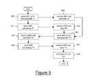
- FIG. 5 schematically shows the exchange of alignment messages mentioned above.
- the exchange of alignment messages between the ingress node IN and the intermediate node N1 preferably comprises the flowing steps: 500) the ingress synchronization interface ISI generates a timestamp T1 equal to the current value of the ingress time counter TCI and the ingress node IN preferably sends a first alignment message AM1.
- the first alignment message AM1 comprises the timestamp T1 (this option is not shown in Figure 5 ); 501) if first alignment message AM1 does not comprise the timestamp T1, the ingress node IN preferably sends a second alignment message AM2 containing the timestamp T1 to the intermediate node N1; 502) the intermediate node N1 preferably receives the first alignment message AM1 and, substantially at the same time, the intermediate synchronization interface SI1 generates a timestamp T2 equal to the current value of the intermediate time counter TC1.
- the intermediate synchronization interface SI1 further extracts the timestamp T1 from the first alignment message AM1 (option not shown in Figure 5 ); 503) if first alignment message AM1 does not comprise the timestamp T1, the intermediate node N1 preferably receives the second alignment message AM2 and the intermediate synchronization interface SI1 extracts the timestamp T1 from the second alignment message AM2; 504) the intermediate node N1 preferably sends a third alignment message AM3 to the ingress node IN and, substantially at the same time, the intermediate synchronization interface SI1 generates a timestamp T3 equal to the current value of the intermediate time counter TC1; 505) the ingress node IN preferably receives the third alignment message AM3 and, substantially at the same time, the ingress synchronization interface ISI generates a timestamp T4 equal to the current value of the ingress time counter TCI; 506) the ingress node IN preferably sends to the intermediate node N1 a fourth
- the steps 500-508 are periodically repeated.
- a lower repetition period advantageously allows reducing the final offset between the intermediate time counter TC1 and the ingress time counter TCI.
- the steps 500-508 are repeated not periodically.
- the average one-way delay is written in a FIFO buffer having size N.
- the offset is written in a further FIFO buffer having the same size N.
- the FIFO buffer is partially full. After N repetitions, the FIFO buffer is completely full.
- steps 500-508 are repeated for the N+1-th time, a new average one-way delay DN+1 is written in the FIFO buffer and the average one-way delay D1 written first in the FIFO buffer is removed.
- the intermediate node N1 Each time a new value of the average one-way delay is written in the FIFO buffer, the intermediate node N1 preferably determines a minimum delay D* amongst the average one-way delay values currently contained in the FIFO buffer. Then, the intermediate node N1 determines an offset TO* corresponding to the minimum delay D*. Then, the intermediate node N1 uses the offset value TO* in order to reduce the offset between the intermediate time counter TC1 and the ingress time counter TCI.
- the offset TO* thus determined is advantageously the nearest, amongst the values currently stored in the further FIFO buffer, to the actual offset TO'.
- the more similar the average one-way delay computed according to the equation [1] is to the delay actually accumulated in the one-way direction the more accurate the estimate of the offset between the intermediate time counter TC1 and the ingress time counter TCI is.
- this is more likely to happen when the traffic on the link between the intermediate node N1 and the ingress node IN is low, i.e. when the delay is a minimum.
- the packet-switched network PN is intrinsically symmetric (i.e. the capacity of each link is the same in both directions). This guarantees that the minimum delay is also symmetric, i.e. it is the same in both directions.
- the intermediate node N1 preferably sums the value of the offset TO* to the current value of the intermediate time counter TC1, as shown in Figure 6 . If the offset TO* is equal to the actual offset TO' (i.e. st1-stI), this operation allows aligning the intermediate time counter TC1 and the ingress time counter TCI. If, on the contrary, as shown on Figure 6 , the offset TO* is different from the actual offset TO' (i.e. st1-stI), this operation allows anyway reducing (but not cancelling) the offset between the intermediate time counter TC1 and the ingress time counter TCI.
- the offset TO* is equal to the actual offset TO' (i.e. st1-stI)
- this operation allows anyway reducing (but not cancelling) the offset between the intermediate time counter TC1 and the ingress time counter TCI.
- the offset can be further reduced.
- the offset thus decreases in time and, with a not predictable number of repetitions of steps 500-508, it can be cancelled so that the intermediate time counter TC1 and the ingress time counter TCI are aligned.
- the intermediate node N1 and the egress node EN preferably set a bi-directional exchange of alignment messages thanks to which the egress node EN reduces the offset between the egress time counter TCE and the intermediate time counter TC1.
- the messages exchange and the successive processing of their content by the egress node EN is identical to what has been described above with reference to Figure 5 . Therefore, a detailed description will not be repeated here.
- the intermediate time counter TC1 and the egress time counter TCE gradually reduce their offset with respect to the ingress time counter TCI and, within a not predictable time interval, they can align with respect to the ingress time counter TCI.
- the ingress node IN may decide to restart the alignment procedure and accordingly send to the nodes that are aligning their time counters with it suitable commands to reset their FIFO buffers and their further FIFO buffers.
- the ingress node IN preferably sends to the intermediate node N1 (for instance embedded in one of the alignment messages exchanged with the intermediate node N1) a command to restart the alignment procedure.
- the intermediate node N1 preferably propagates this command to the egress node EN within one of the alignment messages exchanged with the egress node EN.
- the command is propagated node by node from the ingress node IN through the whole packet-switched network PN'.
- the command to restart the alignment procedure may be manually input by an operator at a node (either the ingress node IN or a further node) of the packet-switched network PN'.
- the command is then propagated by the node receiving the manual command to the nodes that are trying to align their time counters to the time counter of that node.
- the master node MN sends a synchronization message SM (e.g. a Sync message containing a first timestamp t1 according to the IEEE 1588 TM -2008 protocol) to the ingress node IN of the packet-switched network PN' through the ingress link IL.
- a synchronization message SM e.g. a Sync message containing a first timestamp t1 according to the IEEE 1588 TM -2008 protocol
- the intermediate time counter TC1 and the egress time counter TCE are aligned with respect to the ingress time counter TCI.
- the ingress synchronization interface ISI of the ingress node IN reads the current value t1* of the ingress time counter TCI and generates an ingress timestamp with the value t1*.
- the ingress synchronization interface ISI preferably encapsulates the synchronization message SM in a transfer message SM' which further comprises the timestamp with the value t1*.
- the ingress node IN sends the transfer message SM' which, through the intermediate node N1, reaches the egress node EN of the packet-switched network PN'.
- the intermediate node N1 receives the transfer message SM' from the ingress node IN and forwards it to the egress node EN without performing any processing of the ingress timestamp with the value t1*.
- the egress synchronization interface ESI When the egress node EN receives the transfer message SM', the egress synchronization interface ESI preferably reads the ingress timestamp with the value t1*, extracts the synchronization message SM and terminates the transfer message SM'. The egress synchronization interface ESI then preferably reads the current value t2* of the output of the egress time counter TCE and generates an egress timestamp with the value t2*. Then it computes a transit time TT as the difference between such egress timestamp and the ingress timestamp, i.e. the difference t2*-t1*, and writes this difference in the adjusting field AF of the header H-SM of the synchronization message SM.
- the transit time TT according to this second embodiment is substantially equal to the actual transit time TTE (i.e. the time interval elapsed between the time at which the synchronization message SM has been received by the ingress node IN and the time at which the synchronization message SM has been sent by the egress node EN), since the offset TO between the egress time counter TCE and the ingress time counter TCI is zero.
- the offset TO between the egress time counter TCE and the ingress time counter TCI is not zero, it is anyway lower than the initial value stE-stI thanks to the exchanges of alignment messages described above.
- the slave node SN When the slave node SN receives the synchronization message SM, it preferably reads both the synchronization information contained in it (i.e.. the timestamp t1) and the content of the adjusting field AF which contains the transit time TT. Then, preferably, the slave node SN uses the transit time TT to adjust the value of the timestamp t1 so as to synchronize the frequency and the time of the day of its local clock to the master node MN. This operation will not be described here in greater detail since it is similar to the operation defined by the IEEE 1588 TM -2008 protocol, and it does not fall within the scope of the present invention.
- the accuracy of the time of the day synchronization depends on the period of the reference clock signal generated by the synchronization source apparatus SSA. For example, if the period of this signal is of the order of nanoseconds, the time of the local clock of the slave node SN can be synchronized to the local clock of the master node MN with a resolution of the order of nanoseconds.
- the slave node SN is able to reliably and accurately synchronize both the frequency and the time of the day to the master node MN.
- the implementation of the offset reduction at the nodes of the packet-switched network PN' requires a lower amount of hardware and/or software resources than the implementation of the known transparent clock mechanism described above.
- the alignment messages advantageously may have smaller dimensions than the synchronization messages used to implement the transparent clock mechanism.
- the bandwidth required for the implementation of the offset reduction is thus advantageously lower than the bandwidth required to implement message exchange required for implementing the transparent clock mechanism according to the known IEEE 1588 TM -2008.
- the ingress node IN and the egress node EN are preferably provided with respective GPS (Global Positioning System) receivers suitable for receiving a GPS time-of-the-day information.
- GPS Global Positioning System
- the ingress node IN and the egress node EN may use this GPS time-of-the-day information for aligning their time counters TCI and TCE, respectively. In this case, therefore, the above alignment procedure implemented by exchanging alignment messages is not required.
Landscapes
- Engineering & Computer Science (AREA)
- Computer Networks & Wireless Communication (AREA)
- Signal Processing (AREA)
- Synchronisation In Digital Transmission Systems (AREA)
- Data Exchanges In Wide-Area Networks (AREA)
- Mobile Radio Communication Systems (AREA)
Abstract
Description
- The present invention generally relates to the field of radio communication networks. In particular, the present invention relates to transfer of a synchronization message through a packet radio network.
- In a packet-switched communication network, two or more nodes may synchronize each other according to a master-slave scheme by exchanging synchronization messages. In particular, the synchronization messages allow one or more slave nodes to synchronize the frequency of their local clock and/or the time of the day (i.e. hours, minutes, seconds and possible fractions of seconds) of their local clock to a master node.
- For a packet-switched communication network, for example an Ethernet network, network protocols are known implementing the synchronization, such as the IEEE 1588™-2008 protocol which is defined in document "IEEE Standard for a Precision Clock Synchronization Protocol for Networked Measurements and Control Systems" by IEEE Instrumentation and Measurements Society, July 24, 2008.
- According to IEEE 1588™-2008 protocol (see document cited above, chapter 6, paragraph 6.6.3, pp. 32-34), the master node sends a Sync message to a slave node and generates a first timestamp t1 indicating the time at which the master node sends the Sync message. The first timestamp t1 is sent to the slave node within the Sync message itself or within a Follow-Up message that the master node sends to the slave node after the Sync message. The slave node in turn receives the Sync message and generates a second timestamp t2 indicating the time at which the slave node receives the Sync message. The slave node then sends to the master node a Delay_Req message and generates a third timestamp t3 indicating the time at which the slave node sends such message. The master node receives the Delay_Req message and generates a fourth timestamp t4 indicating the time at which it receives such message and in turn sends to the slave node the fourth timestamp t4 within a Delay_Resp message.
- At the end of the messages exchange described above, the four timestamps t1, t2, t3, t4 are available at the slave node. The above described message exchange is typically periodically repeated. By using one or more of the four timestamps t1, t2, t3, t4, the slave node is able to synchronize the frequency and the time of the day of its local clock to those of the master node local clock.
- In particular, according to IEEE 1588™-2008 protocol (see the document cited above, chapter 12, paragraph 12.1.2, pp. 122-123), the slave node adjusts the frequency of its local clock by using a frequency factor equal to the ratio of the difference between two successive second timestamps t2 to the difference between two successive first timestamps t1.
- Typically, the synchronization messages sent by the master (slave) node are received at the slave (master) node with a delay due to the message propagation on the links and to the message residence within the intermediate nodes. Such delay is affected by not predictable variations which are mainly due to the fact that the residence time of the synchronization messages within the intermediate nodes varies in a not predictable way according to the traffic conditions inside the packet-switched network. The greater the variations of the synchronization message delay, the lower the accuracy of the synchronization recovery by the slave node.
- On the other hand, the traffic on the link connecting the master node and the slave node is typically asymmetric. This means that the delay that the synchronization messages experience in the master-to-slave direction is different from the delay that the synchronization messages experience in the slave-to-master direction. The higher the difference of the message delay in the directions master-to-slave and slave-to-master, the lower the accuracy of the time of the day recovery by the slave node. Moreover, also this difference varies in a not predictable way.
- The IEEE 1588™-2008 protocol provides for implementing a "transparent clock" mechanism (see chapter 6, paragraph 6.5.4 of the document cited above) at the nodes of the packet-switched network. This mechanism provides for measuring, at a node receiving a IEEE 1588™-2008 protocol message, a residence time of such message within the node. The residence time is written in a Correction Field of the synchronization message header. In order to estimate the overall delay of the synchronization message, each network node comprised in the synchronization message path computes the residence time of the synchronization message and updates the Correction Field by suitably incrementing the value contained therein. The slave node receives the synchronization message and, according to the value contained in the Correction Field, adjusts the value of the timestamp carried by the synchronization message.
- The above described IEEE 1588™-2008 protocol can be used in a radio mobile access system comprising a radio network controller, a number of base stations and a backhauling wireless network connecting the radio network controller and the base stations. In this scenario, the base stations (which act as slave nodes) synchronize to the radio network controller (which acts as master node) by exchanging the above described messages through the backhauling wireless network. More particularly, the radio network controller and the base stations comprise dedicated apparatuses configured to act as master node and slave nodes, respectively.
- The inventors have noticed that the transparent clock mechanism allows to consider the delay accumulated by the synchronization message and to reduce accordingly the effect of the delay variation due to the message residence within the nodes.
- However, disadvantageously, the transparent clock mechanism requires that all the packet-switched network nodes are equipped with hardware and/or software resources configured to support such mechanism. This disadvantageously leads to high costs for the mechanism implementation, as it is necessary to modify all the network nodes. Moreover, this way, all the network nodes have a more complex structure. This disadvantageously leads to increasing the maintenance costs of the network.
- Furthermore, as mentioned above, according to the transparent clock mechanism, each node must compute the residence time and write it in the Correction Field at the time at which the synchronization message is forwarded to the next node, i.e. at the output physical interface of the node. If the packet-switched network is a wireless packet-switched network, the output physical interface of the node is a radio physical interface. This radio interface typically comprises functional blocks (e.g. scrambler, encoder, interleaver, modem, etc.) that are transparent and agnostic with respect to the Correction Field and the time stamps carried by the synchronization messages, since they merely act at the radio physical layer. Disadvantageously, the Correction Field is written before the synchronization message is processed by the radio interface. This disadvantageously implies that the residence time written in the Correction Field does not take into account the variable delay introduced by processing of the synchronization messages at the radio interface.
- Accordingly, the inventors have addressed the problem of providing a method for transferring a synchronization message through a wireless packet-switched communication network which overcomes the aforesaid drawbacks.
- In particular, the inventors have addressed the problem of providing a method for transferring a synchronization message through a wireless packet-switched communication network, allowing the slave node to recover the synchronization in a reliable and accurate way and, at the same time, requiring a lower amount of additional resources at the nodes of the packet-switched network with respect to the amount required for implementing the known transparent clock mechanism.
- According to a first aspect, the present invention provides a method for transferring a synchronization message from a master node to a slave node through a packet-switched network, the method comprising the steps of:
- a) providing a reference clock signal to an ingress node and to an egress node of the packet-switched network;
- b) at the ingress node, receiving the synchronization message from the master node, generating an ingress timestamp based on the reference clock signal, and sending the synchronization message with the ingress timestamp to the egress node; and
- c) at the egress node, receiving the synchronization message and the ingress timestamp, generating an egress timestamp based on the reference clock signal, computing a transit time as a difference between the egress timestamp and the ingress timestamp and sending the synchronization message and the transit time to the slave node.
- Preferably, step b) comprises receiving the reference clock signal, processing the reference clock signal for generating a first local clock signal having a first period, and providing an ingress time counter counting a number of periods of the first local clock signal, and step c) comprises receiving the reference clock signal, processing the reference clock signal for generating a second local clock signal having a second period, and providing an egress time counter counting a number of periods of the second local clock signal, the first period being substantially equal to the second period.
- Preferably, in step b), generating comprises reading a first current value of the ingress time counter and generating the ingress timestamp having the first current value, and in step c), generating comprises reading a second current value of the egress time counter and generating the egress timestamp having the second current value.
- Preferably, counting a number of periods of the first local clock signal is started at a first starting time, and counting a number of periods of the second local clock signal is started at a second starting time, a difference between the first starting time and the second starting time being equal to an offset between the ingress time counter and the egress time counter.
- Preferably, the method further comprises a step, which is performed substantially in parallel to steps b) and c), of reducing or cancelling the offset.
- According to first advantageous variants, the step of reducing or cancelling the offset comprises providing the ingress node and the egress node with a global positioning system time-of-the-day information.
- According to second advantageous variants, the step of reducing or cancelling the offset comprises exchanging at least one alignment message between the ingress node and an intermediate node of the packet-switched network adjacent to the ingress node.
- Preferably, according to these second advantageous variants, step a) further comprises providing the reference clock signal to an intermediate node of the packet switched network, the method further comprising, at the intermediate node:
- receiving the reference clock signal;
- processing the reference clock signal for generating a third local clock signal having a third period, the third period being substantially equal to the first period and the second period;
- providing an intermediate time counter counting a number of periods of the third local clock signal, the counting being started at a third starting time, a difference between the third starting time and the first starting time being equal to a further offset between the intermediate time counter and the ingress time counter.
- Preferably, the step of exchanging at least one alignment message between the ingress node and the intermediate node comprises cyclically repeating the following sub-steps:
- at the ingress node, generating a first timestamp T1 equal to a third current value of the ingress time counter and sending a first alignment message to the intermediate node;
- at the ingress node, sending a second alignment message containing the first timestamp T1 to the intermediate node;
- at the intermediate node, upon reception of the first alignment message, generating a second timestamp T2 equal to a fourth current value of the intermediate time counter and, upon reception of the second alignment message, extracting the first timestamp T1 from the second alignment message;
- at the intermediate node, sending a third alignment message to the ingress node and, substantially at the same time, generating a third timestamp T3 equal to a fifth current value of the intermediate time counter;
- at the ingress node, upon reception of the third alignment message, generating a fourth timestamp T4 equal to a sixth current value of the ingress time counter, and sending to the intermediate node a fourth alignment message comprising the fourth timestamp T4;
- at the intermediate node, upon reception of the fourth alignment message, extracting the fourth timestamp T4 from the fourth alignment message and computing an average one-way delay D1 by means of the following equation:

and a still further offset TO1 by means of the following equation:
- at the intermediate node, writing the average one-way delay D1 in a FIFO buffer having size N, and writing the still further offset T01 in a further FIFO buffer having the size N;
- at the intermediate node, determining a minimum delay D* in the FIFO buffer, and determining a corresponding offset TO* corresponding to the minimum delay D* in the further FIFO buffer; and
- at the intermediate node, using the corresponding offset TO* in order to reduce the further offset between the intermediate time counter and the ingress time counter.
- Preferably, in step b), sending comprises encapsulating the synchronization message and the ingress timestamp in a transfer message, and in step c) receiving comprises extracting the synchronization message and the ingress timestamp from the transfer message.
- Preferably, in step b) sending comprises inserting the ingress timestamp in a body of the synchronization message, and in step c) receiving comprises extracting the ingress timestamp from the body of the synchronization message.
- Preferably, in step c) sending comprises writing the transit time in an adjusting field of a header of the synchronization message.
- According to a second aspect, the present invention provides a communication system comprising a packet-switched network, a master node and a slave node, the packet-switched network comprising an ingress node connected to the master node and an egress node connected to the slave node, the communication system further comprising a synchronization source apparatus cooperating with the packet-switched network, wherein:
- the synchronization source apparatus is configured to provide a reference clock signal to the ingress node and to the egress node;
- the master node is configured to transmit a synchronization message to the slave node through the ingress node and the egress node;
- the ingress node is configured to receive the synchronization message from the master node, to generate an ingress timestamp based on the reference clock signal, and to send the synchronization message with the ingress timestamp to the egress node; and
- the egress node is configured to receive the synchronization message and the ingress timestamp from the ingress node, to generate an egress timestamp based on the reference clock signal, to compute a transit time as a difference between the egress timestamp and the ingress timestamp and to send the synchronization message and the transit time to the slave node.
- Preferably, the synchronization source apparatus is a node of the packet-switched network or an apparatus cooperating with the packet-switched network.
- Preferably, the ingress node comprises an ingress local oscillator and an ingress time counter connected to the ingress local oscillator, wherein the ingress local oscillator is configured to receive the reference clock signal and to process the reference clock signal for generating a first local clock signal having a first period, and wherein the ingress time counter is configured to count a number of periods of the first local clock signal, and the egress node comprises an egress local oscillator and an egress time counter connected to the egress local oscillator, wherein the egress local oscillator is configured to receive the reference clock signal and to process the reference clock signal for generating a second local clock signal having a second period, and wherein the egress time counter is configured to count a number of periods of the second local clock signal.
- Embodiments of the invention will be better understood by reading the following detailed description, given by way of example and not of limitation, to be read with reference to the accompanying drawings, wherein:
-
Figure 1 schematically shows a communication system comprising a master node, a slave node and a wireless packet-switched network, according to a first embodiment of the present invention; -
Figure 2 is a schematic time diagram of the time counters at the ingress node and the egress node of the wireless packet-switched network; -
Figures 3a, 3b and 3c schematically show the format of the synchronization messages sent by the master node to the slave node according to an advantageous variant of the present invention; -
Figure 4 schematically shows a communication system comprising a master node, a slave node and a wireless packet-switched network, according to a second embodiment of the present invention; -
Figure 5 is a flow chart of the messages exchange between the ingress node and an intermediate node of the packet-switched network ofFigure 4 , according to the second embodiment of the present invention; and -
Figure 6 is a schematic time diagram of the time counters at the ingress node and at the intermediate node of the packet-switched network ofFigure 4 , according to the second embodiment of the present invention. -
Figure 1 schematically shows a communication system CS, comprising a master node MN, a slave node SN and a packet-switched network PN connecting the master node MN and the slave node SN. The communication system CS further comprises a synchronization source apparatus SSA. The synchronization source apparatus SSA may be a node of the packet-switched network PN or an external apparatus cooperating with the packet-switched network PN and connected to one or more nodes of the packet-switched network PN. - For example, the communication system CS can be a radio mobile access system. In such a case, the master node MN is, for example, a radio network controller (RNC) node, the slave node SN is a radio base station and the packet-switched network PN is a wireless backhauling network.
- The slave node SN is configured to synchronize its local clock frequency and/or its local clock time of the day to the master node MN. In particular, the master node MN and the slave node SN are preferably configured to exchange synchronization messages through the packet-switched network PN according to a network protocol implementing the synchronization, such as for example, the IEEE 1588™-2008 protocol cited above.
- The packet-switched network PN preferably comprises an ingress node IN, an egress node EN and one or mode intermediate nodes (not shown in
Figure 1 ). The ingress node IN is a peripheral node which is connected to the master node MN through an ingress link IL and the egress node EN is a peripheral node which is connected to the slave node SN through an egress link EL. The packet-switched network PN is for example a wireless Ethernet network. - Preferably, both the ingress link IL and the egress link EL are bi-directional links. Preferably, both the ingress link IL and the egress link EL are wired links. Further, according to a variant not shown in the drawings, the ingress link IL and the egress link EL may be replaced by two further communication networks by means of which the ingress node IN and the egress node EN are connected to the master node MN and slave node SN, respectively.
- Preferably, the ingress node IN is configured to receive from the master node MN synchronization messages through the ingress link IL and to forward such synchronization messages to one of the intermediate nodes of the packet-switched network PN. Moreover, the ingress node IN is configured to receive synchronization messages from one or more intermediate nodes of the packet-switched network PN and to forward such synchronization messages to the master node MN through the ingress link IL.
- Preferably, the egress node is configured to receive synchronization messages from one or more intermediate nodes of the packet-switched network PN and to forward such synchronization messages to the slave node SN through the egress link EL. Moreover, the egress node EN is configured to receive from the slave node SN synchronization messages through the egress link EL and to forward such synchronization messages to one of the intermediate nodes of the packet-switched network PN.
- According to preferred embodiments of the present invention, the ingress node IN comprises an ingress local clock IC and an ingress synchronization interface ISI connected to the ingress local clock IC. In turn, the ingress local clock IC comprises an ingress local oscillator ILO and an ingress time counter TCI connected to the ingress local oscillator ILO. The egress node EN preferably comprises an egress local clock EC and an egress synchronization interface ESI, connected to the egress local clock EC. In turn, the egress local clock EC comprises an egress local oscillator ELO and an egress time counter TCE connected to the egress local oscillator ELO.
- The synchronization source apparatus SSA is preferably configured to generate a reference clock signal, that is propagated across the packet-switched network PN so that at least the ingress local oscillator ILO and to the egress local oscillator ELO of the ingress node IN and of the egress node EN, respectively, receive it. More preferably, the local oscillators of all the nodes of the packet-switched network PN receive the reference clock signal.
- Preferably, the ingress local oscillator ILO and the egress local oscillator ELO are adapted for processing the reference clock signal in order to generate respective clock signals having periods cpl and cpE. The periods cpl and cpE are preferably substantially equal. The periods cpl and cpE are preferably equal to a fraction of a second, for example few nanoseconds.
- Preferably, the ingress time counter TCI is configured to count the number of periods of the clock signal of the ingress local oscillator ILO, starting from a starting time stI. Likewise, the egress time counter TCE is configured to count the number of periods of the clock signal of the egress local oscillator ELO starting from a starting time stE.
-
Figure 2 schematically shows the values of the ingress time counter TCI and of the egress time counter TCE as a function of time. The values of each of the ingress time counter TCI and the egress time counter TCE as a function of time are schematically represented, for sake of simplicity, by respective monotonic rising and piecewise constant curves. Such curves represent the number of the clock signal periods which are counted starting from the starting time stI or stE. At each period cpl or cpE, this number is incremented by one. - Since, as mentioned above, the periods cpl and cpE are substantially equal, in
Figure 2 the two curves corresponding to the ingress time counter TCI and the egress time counter TCE are substantially parallel. If the starting times stI and stE are different, the ingress time counter TCI and the egress time counter TCE are misaligned in time by an offset TO. Since the periods cpl and cpE are substantially equal, the offset TO is substantially constant and it is substantially equal to stE-stI. - The ingress synchronization interface ISI and the egress synchronization interface ESI are preferably hardware and/or software modules adapted for processing the synchronization messages received by the ingress node IN and the egress node EN, respectively, as it will be explained in greater detail herein after.
- With reference to
Figure 1 , herein after the operation of the communication system CS will be described in detail. For sake of simplicity, only the case in which a synchronization message is sent from the master node MN to the slave node SN will be considered. However, this is not limiting since the operation of the communication system CS in the opposite direction is the same. - It is assumed, for example, that the master node MN generates a synchronization message SM in order to send a timestamp to the slave node SN.
-
Figure 3a shows the format of the synchronization message SM. The synchronization message SM preferably comprises a header H-SM and a body B-SM. The header H-SM preferably comprises an adjusting field AF suitable for containing a transit time, as it will be explained in greater detail herein after. The body B-SM preferably comprises the timestamp. Preferably, the synchronization message SM is a IEEE 1588™ -2008 protocol message. In this case, preferably, the adjusting field AF is the Correction Field defined by to IEEE 1588™-2008 protocol. For example, the synchronization message SM can be a Sync or Follow-Up message carrying the first timestamp t1, as it is shown inFigure 3a by way of example. Alternatively, the synchronization message SM can be a Delay_Resp message carrying the fourth timestamp t4. - As shown in
Figure 1 , the master node MN sends the synchronization message SM to the ingress node IN of the packet-switched network PN through the ingress link IL. Preferably, when the synchronization message SM reaches the ingress node IN, the ingress synchronization interface ISI of the ingress node IN reads the current value t1* of the ingress time counter TCI and generates an ingress timestamp having the value t1*. It is to be noticed that, since the ingress link IL is wired, the delay between the time at which the synchronization message SM is received at the ingress node IN and the time at which the ingress timestamp with the value t1* is generated can advantageously be estimated a priori or is negligible. - At this time, the ingress synchronization interface ISI preferably encapsulates the synchronization message SM in a transfer message SM' which further comprises the ingress timestamp with the value t1*. The format of the transfer message SM' is shown in
Figure 3b . Alternatively, the ingress timestamp with the value t1* may be inserted into the body B-SM of the synchronization message SM. In case the synchronization message SM comprises a frame check sequence, this frame check sequence is recalculated after the ingress timestamp with the value t1* has been inserted into the body B-SM. - Next, the ingress node IN sends the transfer message SM' which, through the intermediate nodes of the packet-switched network PN, reaches the egress node EN of the packet-switched network PN. Preferably, each of the intermediate nodes receives the transfer message SM' from the preceding intermediate node and forwards it to the next intermediate node without performing any processing of the ingress timestamp with the value t1*.
- When the egress node EN receives the transfer message SM', the egress synchronization interface ESI preferably reads the ingress timestamp with the value t1*, extracts the synchronization message SM and terminates the transfer message SM'. The egress synchronization interface ESI then preferably reads the current value t2* of the output of the egress time counter TCE and generates an egress timestamp with the value t2*. Then it computes a transit time TT as the difference between such egress timestamp and the ingress timestamp, i.e. the difference t2*-t1*, and writes this difference in the adjusting field AF of the header H-SM of the synchronization message SM. Next, the egress node EN sends the synchronization message SM to the slave node SN through the egress link EL. It is to be noticed that, since the egress link EL is wired, the delay between the time at which the egress timestamp with the value t2* is generated and the time at which the synchronization message SM is sent by the egress node EN may be advantageously estimated a priori or is negligible.
- As shown in
Figure 2 , the transit time TT depends both on the actual transit time TTE (i.e. the time interval elapsed between the time at which the synchronization message SM has been received by the ingress node IN and the time at which the synchronization message SM has been sent by the egress node EN) and on the offset TO between the egress time counter TCE and the ingress time counter TCI. In particular, the transit time TT is substantially equal to the difference between the actual transit time TTE and the offset TO. InFigure 2 , for example, the offset TO is positive since the egress time counter TCE is delayed with respect to the ingress time counter TCI. Therefore, in this situation, the transit time TT which is computed by the egress node EN is lower that the actual transit time TTE. - When the slave node SN receives the synchronization message SM, it preferably reads both the synchronization information contained therein (i.e. the timestamp t1) and the content of the adjusting field AF which contains the transit time TT. Thus, preferably, the slave node SN uses the transit time TT to adjust the value of the timestamp t1 so as to synchronize the frequency of its local clock to the frequency of the local clock of the master node MN. This operation is similar to the operation defined in the IEEE 1588™-2008 protocol, and it does not fall within the scope of the present invention.
- Advantageously, even of the transit time TT is not equal to the actual transit time TTE, the slave node SN is nevertheless able to accurately synchronize the frequency of its local clock to the frequency of the local clock of the master node MN.
- Indeed, as described above, in order to synchronize the frequency of its local clock, the slave node SN uses a frequency factor which depends on the difference between two successive first timestamps t1 "-t1' received from the master node MN. According to the first embodiment of the present invention, the slave node SN receives a synchronization message (similar to the message SM) comprising the first timestamp t1' and a first transit time TT', and a successive synchronization message (similar to the message SM) comprising a successive first timestamp t1" and a second transit time TT". The slave node SN preferably adjusts the values of the two first timestamps t1" and t1' by subtracting from each of them the respective transit time TT" and TT'. Since, as mentioned above, each of the first and second transit times TT" and TT' comprises the offset TO, which is substantially equal for TT" and TT', the difference between the adjusted values of the two first timestamps t1" and t1' does not depend on the offset TO.
- Therefore, advantageously, the method described above allows considering the delay that each synchronization message experiences when it passes through the packet-switched network PN and thus mitigating the effect of the delay variation experienced by messages through the packet-switched network PN. This allows the slave node SN to reliably and accurately recover the frequency synchronization of its local clock.
- Finally, advantageously, transferring the synchronization message as described above requires that only the ingress node IN and the egress node EN of the packet-switched network PN are provided with the respective ingress synchronization interface ISI and the respective egress synchronization interface ESI. This advantageously implies that the above described transferring of synchronization messages through the packet-switched network PN is implemented by adding to the packet-switched network PN an amount of resources which is lower than the amount required to implement the known transparent clock mechanism.
-
Figure 4 shows a communication system CS' according to a second embodiment of the present invention. The communication system CS' is substantially equal to the communication system CS, except for the fact that the packet-switched network PN is substituted by a packet-switched network PN'. The packet-switched network PN', in turn, is substantially equal to the packet-switched network PN, except for the fact that an intermediate (i.e. not peripheral) node N1 thereof has similar structure with respect to the ingress node IN and the egress node EN. More preferably, each intermediate node of the packet-switched network PN' has similar structure with respect to the ingress node IN and the egress node EN. - In particular, the intermediate node N1 preferably comprises an intermediate local clock C1 and an intermediate synchronization interface SI1 connected to the intermediate local clock C1. In turn, the intermediate local clock C1 comprises an intermediate local oscillator LO1 and an intermediate time counter TC1 connected to the intermediate local oscillator LO1. Preferably, in the communication system CS' of
Figure 4 , the synchronization source apparatus SSA is configured to provide the reference clock signal also to the intermediate local oscillator LO1 of the intermediate node N1, possibly through other nodes of the packet-switched network PN'. More preferably, the synchronization source apparatus SSA is configured to distribute the reference clock signal to all the nodes of the packet-switched network PN. The intermediate local oscillator LO1 is preferably adapted for processing the reference clock signal in order to generate a clock signal with a period cp1 substantially equal to the periods cpl and cpE. Preferably, the intermediate time counter TC1 is configured to count the number of periods of the clock signal of the intermediate local oscillator LO1 starting from a starting time st1 generally different from the starting times stI and stE from which the ingress time counter TCI and the egress time counter TCE start. - According to the second embodiment of the present invention, the ingress node IN, the intermediate node N1 and the egress node EN two by two exchange alignment messages in order to reduce or even cancel the offset between the respective time counters TCI, TC1 and TCE. In particular, to this purpose, one of the time counters TCI, TC1, TCE is chosen as reference time counter and the offset of the other two with respect to the reference time counter is reduced.
- With reference to
Figure 4 , it is assumed that, for example, the reference time counter is the ingress time counter TCI. As mentioned above, the offset between the egress time counter TCE and the ingress time counter TCI is TO, which has an initial value equal to stE-stI. It is further assumed that TO' is the offset between the intermediate time counter TC1 and the ingress time counter TCI, which has an initial value equal to st1-stI. - The ingress node IN and the intermediate node N1 preferably set a bi-directional exchange of alignment messages thanks to which the intermediate node N1 reduces the offset of its time counter TC1 with respect to the ingress time counter TC1.
-
Figure 5 schematically shows the exchange of alignment messages mentioned above. The exchange of alignment messages between the ingress node IN and the intermediate node N1 preferably comprises the flowing steps: 500) the ingress synchronization interface ISI generates a timestamp T1 equal to the current value of the ingress time counter TCI and the ingress node IN preferably sends a first alignment message AM1. Optionally, the first alignment message AM1 comprises the timestamp T1 (this option is not shown inFigure 5 );
501) if first alignment message AM1 does not comprise the timestamp T1, the ingress node IN preferably sends a second alignment message AM2 containing the timestamp T1 to the intermediate node N1;
502) the intermediate node N1 preferably receives the first alignment message AM1 and, substantially at the same time, the intermediate synchronization interface SI1 generates a timestamp T2 equal to the current value of the intermediate time counter TC1. If the first alignment message AM1 comprises the timestamp T1, duringstep 502 the intermediate synchronization interface SI1 further extracts the timestamp T1 from the first alignment message AM1 (option not shown inFigure 5 );
503) if first alignment message AM1 does not comprise the timestamp T1, the intermediate node N1 preferably receives the second alignment message AM2 and the intermediate synchronization interface SI1 extracts the timestamp T1 from the second alignment message AM2;
504) the intermediate node N1 preferably sends a third alignment message AM3 to the ingress node IN and, substantially at the same time, the intermediate synchronization interface SI1 generates a timestamp T3 equal to the current value of the intermediate time counter TC1;
505) the ingress node IN preferably receives the third alignment message AM3 and, substantially at the same time, the ingress synchronization interface ISI generates a timestamp T4 equal to the current value of the ingress time counter TCI;
506) the ingress node IN preferably sends to the intermediate node N1 a fourth alignment message AM4 comprising the timestamp T4;
507) the intermediate node N1 receives the fourth alignment message AM4 and the intermediate synchronization interface SI1 extracts the timestamp T4 from the fourth alignment message AM4;
508) the intermediate node N1 preferably computes an average one-way delay D1 by means of the following equation:
and an offset TO1 by means of the following equation:
- Preferably, the steps 500-508 are periodically repeated. A lower repetition period advantageously allows reducing the final offset between the intermediate time counter TC1 and the ingress time counter TCI. Alternatively, the steps 500-508 are repeated not periodically.
- At each repetition, the average one-way delay is written in a FIFO buffer having size N. Correspondingly, the offset is written in a further FIFO buffer having the same size N. When less than N repetitions have been performed, the FIFO buffer is partially full. After N repetitions, the FIFO buffer is completely full. Preferably, when steps 500-508 are repeated for the N+1-th time, a new average one-way delay DN+1 is written in the FIFO buffer and the average one-way delay D1 written first in the FIFO buffer is removed.
- Each time a new value of the average one-way delay is written in the FIFO buffer, the intermediate node N1 preferably determines a minimum delay D* amongst the average one-way delay values currently contained in the FIFO buffer. Then, the intermediate node N1 determines an offset TO* corresponding to the minimum delay D*. Then, the intermediate node N1 uses the offset value TO* in order to reduce the offset between the intermediate time counter TC1 and the ingress time counter TCI.
- The offset TO* thus determined is advantageously the nearest, amongst the values currently stored in the further FIFO buffer, to the actual offset TO'. Indeed, as it can be observed in the above equation [2], the more similar the average one-way delay computed according to the equation [1] is to the delay actually accumulated in the one-way direction, the more accurate the estimate of the offset between the intermediate time counter TC1 and the ingress time counter TCI is. However, this is more likely to happen when the traffic on the link between the intermediate node N1 and the ingress node IN is low, i.e. when the delay is a minimum. It is to be noticed that the packet-switched network PN is intrinsically symmetric (i.e. the capacity of each link is the same in both directions). This guarantees that the minimum delay is also symmetric, i.e. it is the same in both directions.
- Then, the intermediate node N1 preferably sums the value of the offset TO* to the current value of the intermediate time counter TC1, as shown in
Figure 6 . If the offset TO* is equal to the actual offset TO' (i.e. st1-stI), this operation allows aligning the intermediate time counter TC1 and the ingress time counter TCI. If, on the contrary, as shown onFigure 6 , the offset TO* is different from the actual offset TO' (i.e. st1-stI), this operation allows anyway reducing (but not cancelling) the offset between the intermediate time counter TC1 and the ingress time counter TCI. - At each successive repetition of steps 500-508, the offset can be further reduced. The offset thus decreases in time and, with a not predictable number of repetitions of steps 500-508, it can be cancelled so that the intermediate time counter TC1 and the ingress time counter TCI are aligned.
- Next, the intermediate node N1 and the egress node EN preferably set a bi-directional exchange of alignment messages thanks to which the egress node EN reduces the offset between the egress time counter TCE and the intermediate time counter TC1. The messages exchange and the successive processing of their content by the egress node EN is identical to what has been described above with reference to
Figure 5 . Therefore, a detailed description will not be repeated here. - As a result of the exchanges of alignment messages described above, the intermediate time counter TC1 and the egress time counter TCE gradually reduce their offset with respect to the ingress time counter TCI and, within a not predictable time interval, they can align with respect to the ingress time counter TCI.
- Preferably, the ingress node IN may decide to restart the alignment procedure and accordingly send to the nodes that are aligning their time counters with it suitable commands to reset their FIFO buffers and their further FIFO buffers. In this case, the ingress node IN preferably sends to the intermediate node N1 (for instance embedded in one of the alignment messages exchanged with the intermediate node N1) a command to restart the alignment procedure. The intermediate node N1 preferably propagates this command to the egress node EN within one of the alignment messages exchanged with the egress node EN. In case all the nodes of the packet-switched network PN' are configured for supporting the above alignment procedure, the command is propagated node by node from the ingress node IN through the whole packet-switched network PN'. According to a further advantageous variant, the command to restart the alignment procedure may be manually input by an operator at a node (either the ingress node IN or a further node) of the packet-switched network PN'. In this case, preferably, the command is then propagated by the node receiving the manual command to the nodes that are trying to align their time counters to the time counter of that node.
- With reference to
Figure 4 , it is assumed now that the master node MN sends a synchronization message SM (e.g. a Sync message containing a first timestamp t1 according to the IEEE 1588™-2008 protocol) to the ingress node IN of the packet-switched network PN' through the ingress link IL. For sake of simplicity, it is assumed that, when the synchronization message SM is sent, the intermediate time counter TC1 and the egress time counter TCE are aligned with respect to the ingress time counter TCI. - Preferably, when the synchronization message SM reaches the ingress node IN, the ingress synchronization interface ISI of the ingress node IN reads the current value t1* of the ingress time counter TCI and generates an ingress timestamp with the value t1*.
- At this time, the ingress synchronization interface ISI preferably encapsulates the synchronization message SM in a transfer message SM' which further comprises the timestamp with the value t1*.
- Next the ingress node IN sends the transfer message SM' which, through the intermediate node N1, reaches the egress node EN of the packet-switched network PN'. Preferably, the intermediate node N1 receives the transfer message SM' from the ingress node IN and forwards it to the egress node EN without performing any processing of the ingress timestamp with the value t1*.
- When the egress node EN receives the transfer message SM', the egress synchronization interface ESI preferably reads the ingress timestamp with the value t1*, extracts the synchronization message SM and terminates the transfer message SM'. The egress synchronization interface ESI then preferably reads the current value t2* of the output of the egress time counter TCE and generates an egress timestamp with the value t2*. Then it computes a transit time TT as the difference between such egress timestamp and the ingress timestamp, i.e. the difference t2*-t1*, and writes this difference in the adjusting field AF of the header H-SM of the synchronization message SM.
- Advantageously, the transit time TT according to this second embodiment is substantially equal to the actual transit time TTE (i.e. the time interval elapsed between the time at which the synchronization message SM has been received by the ingress node IN and the time at which the synchronization message SM has been sent by the egress node EN), since the offset TO between the egress time counter TCE and the ingress time counter TCI is zero. In any case, even if the offset TO between the egress time counter TCE and the ingress time counter TCI is not zero, it is anyway lower than the initial value stE-stI thanks to the exchanges of alignment messages described above.
- When the slave node SN receives the synchronization message SM, it preferably reads both the synchronization information contained in it (i.e.. the timestamp t1) and the content of the adjusting field AF which contains the transit time TT. Then, preferably, the slave node SN uses the transit time TT to adjust the value of the timestamp t1 so as to synchronize the frequency and the time of the day of its local clock to the master node MN. This operation will not be described here in greater detail since it is similar to the operation defined by the IEEE 1588™-2008 protocol, and it does not fall within the scope of the present invention.
- The accuracy of the time of the day synchronization depends on the period of the reference clock signal generated by the synchronization source apparatus SSA. For example, if the period of this signal is of the order of nanoseconds, the time of the local clock of the slave node SN can be synchronized to the local clock of the master node MN with a resolution of the order of nanoseconds.
- Therefore, advantageously, according to this second embodiment, the slave node SN is able to reliably and accurately synchronize both the frequency and the time of the day to the master node MN.
- In
Figure 4 , for sake of simplicity, it has been assumed that only the intermediate node N1 is configured to implement the reduction of the offset of its time counter with respect to the reference time counter. However, preferably, all the nodes of the packet-switched network PN' are configured to implement the offset reduction. This advantageously allows to "propagate" in cascade the reduction of the offset of the time counters with respect to the reference time counter through the entire packet-switched network PN'. - Advantageously, the implementation of the offset reduction at the nodes of the packet-switched network PN' requires a lower amount of hardware and/or software resources than the implementation of the known transparent clock mechanism described above. Indeed, the alignment messages advantageously may have smaller dimensions than the synchronization messages used to implement the transparent clock mechanism. The bandwidth required for the implementation of the offset reduction is thus advantageously lower than the bandwidth required to implement message exchange required for implementing the transparent clock mechanism according to the known IEEE 1588™-2008.
- According to advantageous variants not shown in the drawings, the ingress node IN and the egress node EN are preferably provided with respective GPS (Global Positioning System) receivers suitable for receiving a GPS time-of-the-day information. Advantageously, the ingress node IN and the egress node EN may use this GPS time-of-the-day information for aligning their time counters TCI and TCE, respectively. In this case, therefore, the above alignment procedure implemented by exchanging alignment messages is not required.
Claims (15)
- A method for transferring a synchronization message (SM) from a master node (MN) to a slave node (SN) through a packet-switched network (PN, PN'), said method comprising the steps of:a) providing a reference clock signal to an ingress node (IN) and to an egress node (EN) of said packet-switched network (PN);b) at said ingress node (IN), receiving said synchronization message (SM) from said master node (MN), generating an ingress timestamp (t1*) based on said reference clock signal, and sending said synchronization message (SM) with said ingress timestamp (t1*) to said egress node (EN); andc) at said egress node (EN), receiving said synchronization message (SM) and said ingress timestamp (t1*), generating an egress timestamp (t2*) based on said reference clock signal, computing a transit time (TT) as a difference between said egress timestamp (t2*) and said ingress timestamp (t1*) and sending said synchronization message (SM) and said transit time (TT) to said slave node (SN).
- The method according to claim 1, wherein:- said step b) comprises receiving said reference clock signal, processing said reference clock signal for generating a first local clock signal having a first period (cpI), and providing an ingress time counter (TCI) counting a number of periods of said first local clock signal; and- said step c) comprises receiving said reference clock signal, processing said reference clock signal for generating a second local clock signal having a second period (cpE), and providing an egress time counter (TCE) counting a number of periods of said second local clock signal, said first period (cpI) being substantially equal to said second period (cpE).
- The method according to claim 2, wherein:- in said step b), said generating comprises reading a first current value (t1*) of said ingress time counter (TCI) and generating said ingress timestamp (t1*) having said first current value (t1*); and- in said step c), said generating comprises reading a second current value (t2*) of said egress time counter (TCE) and generating said egress timestamp (t2*) having said second current value (t2*).
- The method according to claim 2 or 3, wherein:- said counting a number of periods of said first local clock signal is started at a first starting time (stI); and- said counting a number of periods of said second local clock signal is started at a second starting time (stE),
a difference between said first starting time (stI) and said second starting time (stE) being equal to an offset (TO) between said ingress time counter (TCI) and said egress time counter (TCE). - The method according to claim 4, wherein said method further comprises a step, which is performed substantially in parallel to said steps b) and c), of reducing or cancelling said offset (TO).
- The method according to claim 5, wherein said step of reducing or cancelling said offset (TO) comprises providing said ingress node (IN) and said egress node (EN) with a global positioning system time-of-the-day information.
- The method according to claim 5, wherein said step of reducing or cancelling said offset (TO) comprises exchanging at least one alignment message between said ingress node (IN) and an intermediate node (N1) of said packet-switched network (PN) adjacent to said ingress node (IN).
- The method according to claim 7, wherein step a) further comprises providing said reference clock signal to an intermediate node (N1) of said packet switched network (PN), said method further comprising, at said intermediate node (N1):- receiving said reference clock signal;- processing said reference clock signal for generating a third local clock signal having a third period (cp1), said third period (cp1) being substantially equal to said first period (cpI) and said second period (cpE); and- providing an intermediate time counter (TC1) counting a number of periods of said third local clock signal, said counting being started at a third starting time (st1), a difference between said third starting time (st1) and said first starting time (stI) being equal to a further offset (TO') between said intermediate time counter (TC1) and said ingress time counter (TCI).
- The method according to claim 8, wherein said step of exchanging at least one alignment message between said ingress node (IN) and said intermediate node (N1) comprises cyclically repeating the following sub-steps:- at said ingress node (IN), generating a first timestamp T1 equal to a third current value of said ingress time counter (TCI) and sending a first alignment message (AM1) to said intermediate node (N1);- at said ingress node (IN), sending a second alignment message (AM2) containing said first timestamp T1 to said intermediate node (N1);- at said intermediate node (N1), upon reception of said first alignment message (AM1), generating a second timestamp T2 equal to a fourth current value of said intermediate time counter (TC1) and, upon reception of said second alignment message (AM2), extracting said first timestamp T1 from said second alignment message (AM2);- at said intermediate node (N1), sending a third alignment message (AM3) to said ingress node (IN) and, substantially at the same time, generating a third timestamp T3 equal to a fifth current value of said intermediate time counter (TC1);- at said ingress node (IN), upon reception of said third alignment message (AM3), generating a fourth timestamp T4 equal to a sixth current value of said ingress time counter (TCI), and sending to said intermediate node (N1) a fourth alignment message (AM4) comprising said fourth timestamp T4;- at said intermediate node (N1), upon reception of said fourth alignment message (AM4), extracting said fourth timestamp T4 from said fourth alignment message (AM4) and computing an average one-way delay D1 by means of the following equation:

and a still further offset TO1 by means of the following equation: - at said intermediate node (N1), writing said average one-way delay D1 in a FIFO buffer having size N, and writing said still further offset TO1 in a further FIFO buffer having said size N;- at said intermediate node (N1), determining a minimum delay D* in the FIFO buffer, and determining a corresponding offset TO* corresponding to said minimum delay D* in said further FIFO buffer; and- at said intermediate node (N1), using said corresponding offset TO* in order to reduce said further offset (TO') between said intermediate time counter (TC1) and said ingress time counter (TCI).
 - The method according to any of the preceding claims, wherein:- in said step b), said sending comprises encapsulating said synchronization message (SM) and said ingress timestamp (t1*) in a transfer message (SM'); and- in said step c), said receiving comprises extracting said synchronization message (SM) and said ingress timestamp (t1*) from said transfer message (SM').
- The method according to any of claims 1 to 9, wherein:- in said step b), said sending comprises inserting said ingress timestamp (t1*) in a body (B-SM) of said synchronization message (SM); and- in said step c), said receiving comprises extracting said ingress timestamp (t1*) from said body (B-SM) of said synchronization message (SM).
- The method according to any of the preceding claims, wherein in said step c), said sending comprises writing said transit time (TT) in an adjusting field (AF) of a header (H-SM) of said synchronization message (SM).
- A communication system (CS) comprising a packet-switched network (PN,
PN'), a master node (MN) and a slave node (SN), said packet-switched network (PN) comprising an ingress node (IN) connected to said master node (MN) and an egress node (EN) connected to said slave node (SN), said communication system (CS) further comprising a synchronization source apparatus (SSA) cooperating with said packet-switched network (PN), wherein:- said synchronization source apparatus (SSA) is configured to provide a reference clock signal to said ingress node (IN) and to said egress node (EN);- said master node (MN) is configured to transmit a synchronization message (SM) to said slave node (SN) through said ingress node (IN) and said egress node (EN);- said ingress node (IN) is configured to receive said synchronization message (SM) from said master node (MN), to generate an ingress timestamp (t1*) based on said reference clock signal, and to send said synchronization message (SM) with said ingress timestamp (t1*) to said egress node (EN); and- said egress node (EN) is configured to receive said synchronization message (SM) and said ingress timestamp (t1*) from said ingress node (IN), to generate an egress timestamp (t2*) based on said reference clock signal, to compute a transit time (TT) as a difference between said egress timestamp (t2*) and said ingress timestamp (t1*) and to send said synchronization message (SM) and said transit time (TT) to said slave node (SN). - The communication system (CS) according to claim 13, wherein said
synchronization source apparatus (SSA) is a node of said packet-switched network (PN) or an apparatus cooperating with said packet-switched network (PN). - The communication system (CS) according to claim 13 or 14, wherein:- said ingress node (IN) comprises an ingress local oscillator (ILO) and an ingress time counter (TCI) connected to said ingress local oscillator (ILO), wherein said ingress local oscillator (ILO) is configured to receive said reference clock signal and to process said reference clock signal for generating a first local clock signal having a first period (cpl), and wherein said ingress time counter (TCI) is configured to count a number of periods of said first local clock signal; and- said egress node (EN) comprises an egress local oscillator (ELO) and an egress time counter (TCE) connected to said egress local oscillator (ELO), wherein said egress local oscillator (ELO) is configured to receive said reference clock signal and to process said reference clock signal for generating a second local clock signal having a second period (cpE), and wherein said egress time counter (TCE) is configured to count a number of periods of said second local clock signal.
Priority Applications (4)
| Application Number | Priority Date | Filing Date | Title |
|---|---|---|---|
| EP10305006A EP2341650B1 (en) | 2010-01-05 | 2010-01-05 | Transfer of a synchronization message through a packet radio network |
| PL10305006T PL2341650T3 (en) | 2010-01-05 | 2010-01-05 | Transfer of a synchronization message through a packet radio network |
| ES10305006T ES2384220T3 (en) | 2010-01-05 | 2010-01-05 | Transfer of a synchronization message via a packet radio network |
| AT10305006T ATE550839T1 (en) | 2010-01-05 | 2010-01-05 | TRANSMISSION OF A SYNCHRONIZATION MESSAGE THROUGH A PACKET RADIO NETWORK |
Applications Claiming Priority (1)
| Application Number | Priority Date | Filing Date | Title |
|---|---|---|---|
| EP10305006A EP2341650B1 (en) | 2010-01-05 | 2010-01-05 | Transfer of a synchronization message through a packet radio network |
Publications (2)
| Publication Number | Publication Date |
|---|---|
| EP2341650A1 true EP2341650A1 (en) | 2011-07-06 |
| EP2341650B1 EP2341650B1 (en) | 2012-03-21 |
Family
ID=42153851
Family Applications (1)
| Application Number | Title | Priority Date | Filing Date |
|---|---|---|---|
| EP10305006A Not-in-force EP2341650B1 (en) | 2010-01-05 | 2010-01-05 | Transfer of a synchronization message through a packet radio network |
Country Status (4)
| Country | Link |
|---|---|
| EP (1) | EP2341650B1 (en) |
| AT (1) | ATE550839T1 (en) |
| ES (1) | ES2384220T3 (en) |
| PL (1) | PL2341650T3 (en) |
Cited By (8)
| Publication number | Priority date | Publication date | Assignee | Title |
|---|---|---|---|---|
| CN102957528A (en) * | 2011-08-26 | 2013-03-06 | 中兴通讯股份有限公司 | Synchronizing method and synchronizing system for traversing third-party synchronous network |
| WO2013091202A1 (en) * | 2011-12-21 | 2013-06-27 | 华为技术有限公司 | Synchronization method, device and system |
| EP2847921A4 (en) * | 2012-05-11 | 2015-10-07 | Vitesse Semiconductor Corp | TIME SYNCHRONIZATION FOR NETWORKS HAVING RADIO LINKS |
| CN111698076A (en) * | 2020-06-03 | 2020-09-22 | 河北工业大学 | Accurate communication synchronization method and system based on time compensation |
| CN113141225A (en) * | 2020-01-20 | 2021-07-20 | 中国移动通信集团山东有限公司 | Time synchronization method, device, storage medium and terminal |
| US11418421B2 (en) * | 2018-06-04 | 2022-08-16 | Nippon Telegraph And Telephone Corporation | Measurement system and measurement method |
| CN114079557B (en) * | 2020-08-19 | 2024-04-23 | 智邦科技股份有限公司 | Network device |
| WO2024121492A1 (en) * | 2022-12-09 | 2024-06-13 | Safran | Method for compensating for a delay in a data-transmission network based on the tdma protocol |
Citations (2)
| Publication number | Priority date | Publication date | Assignee | Title |
|---|---|---|---|---|
| US20050058159A1 (en) * | 2003-09-11 | 2005-03-17 | Chapman John T. | System for synchronizing circuitry in an access network |
| US20050207387A1 (en) * | 2004-02-09 | 2005-09-22 | Semtech Corporation | Method and apparatus for aligning time references when separated by an unreliable data packet network |
-
2010
- 2010-01-05 EP EP10305006A patent/EP2341650B1/en not_active Not-in-force
- 2010-01-05 AT AT10305006T patent/ATE550839T1/en active
- 2010-01-05 PL PL10305006T patent/PL2341650T3/en unknown
- 2010-01-05 ES ES10305006T patent/ES2384220T3/en active Active
Patent Citations (2)
| Publication number | Priority date | Publication date | Assignee | Title |
|---|---|---|---|---|
| US20050058159A1 (en) * | 2003-09-11 | 2005-03-17 | Chapman John T. | System for synchronizing circuitry in an access network |
| US20050207387A1 (en) * | 2004-02-09 | 2005-09-22 | Semtech Corporation | Method and apparatus for aligning time references when separated by an unreliable data packet network |
Non-Patent Citations (1)
| Title |
|---|
| "IEEE Standard for a Precision Clock Synchronization Protocol for Networked Measurements and Control Systems", 24 July 2008, IEEE INSTRUMENTATION AND MEASUREMENTS SOCIETY |
Cited By (15)
| Publication number | Priority date | Publication date | Assignee | Title |
|---|---|---|---|---|
| EP2750339A4 (en) * | 2011-08-26 | 2015-01-14 | Zte Corp | SYNCHRONIZATION METHOD AND SYSTEM FOR CROSSING THE SYNCHRONOUS NETWORK OF A THIRD PARTY |
| CN102957528A (en) * | 2011-08-26 | 2013-03-06 | 中兴通讯股份有限公司 | Synchronizing method and synchronizing system for traversing third-party synchronous network |
| CN102957528B (en) * | 2011-08-26 | 2018-03-02 | 中兴通讯股份有限公司 | Pass through the synchronous method and system of third party's synchronizing network |
| CN103597887B (en) * | 2011-12-21 | 2017-10-10 | 华为技术有限公司 | A kind of synchronous method, equipment and system |
| WO2013091202A1 (en) * | 2011-12-21 | 2013-06-27 | 华为技术有限公司 | Synchronization method, device and system |
| US9179429B2 (en) | 2011-12-21 | 2015-11-03 | Huawei Technologies Co., Ltd. | Synchronization method, device, and system |
| EP2847921A4 (en) * | 2012-05-11 | 2015-10-07 | Vitesse Semiconductor Corp | TIME SYNCHRONIZATION FOR NETWORKS HAVING RADIO LINKS |
| US9426762B2 (en) | 2012-05-11 | 2016-08-23 | Microsemi Communications, Inc. | Timing synchronization for networks with radio links |
| US11418421B2 (en) * | 2018-06-04 | 2022-08-16 | Nippon Telegraph And Telephone Corporation | Measurement system and measurement method |
| CN113141225A (en) * | 2020-01-20 | 2021-07-20 | 中国移动通信集团山东有限公司 | Time synchronization method, device, storage medium and terminal |
| CN111698076A (en) * | 2020-06-03 | 2020-09-22 | 河北工业大学 | Accurate communication synchronization method and system based on time compensation |
| CN111698076B (en) * | 2020-06-03 | 2023-05-30 | 河北工业大学 | A precise communication synchronization method and system based on time compensation |
| CN114079557B (en) * | 2020-08-19 | 2024-04-23 | 智邦科技股份有限公司 | Network device |
| WO2024121492A1 (en) * | 2022-12-09 | 2024-06-13 | Safran | Method for compensating for a delay in a data-transmission network based on the tdma protocol |
| FR3143241A1 (en) * | 2022-12-09 | 2024-06-14 | Safran | Delay compensation method in a data transmission network based on the TDMA protocol |
Also Published As
| Publication number | Publication date |
|---|---|
| ES2384220T3 (en) | 2012-07-02 |
| EP2341650B1 (en) | 2012-03-21 |
| PL2341650T3 (en) | 2013-04-30 |
| ATE550839T1 (en) | 2012-04-15 |
Similar Documents
| Publication | Publication Date | Title |
|---|---|---|
| EP2341650B1 (en) | Transfer of a synchronization message through a packet radio network | |
| US8982897B2 (en) | Data block output apparatus, communication system, data block output method, and communication method | |
| KR102031268B1 (en) | Method and apparatus for communicating time information between time-aware devices | |
| KR101749202B1 (en) | Method, apparatus, and system for generating timestamp | |
| US9178637B2 (en) | Method and devices for synchronization using linear programming | |
| US8081663B2 (en) | Time synchronization method and relay apparatus | |
| US9548831B2 (en) | Synchronizing system, synchronizing method, first synchronizing device, second synchronizing device, and computer program | |
| EP2572462B1 (en) | Optimizing timing packet transport | |
| EP2381622A1 (en) | Update of a cumulative residence time of a packet in a packet-switched communication network | |
| CN105187148B (en) | A kind of network clock synchronization system and method based on ARM | |
| US20170064661A1 (en) | Base station system, radio device and method | |
| US20150295702A1 (en) | Synchronization apparatus, synchronization system, radio communication apparatus and synchronization method | |
| US9806876B2 (en) | Method and apparatus for compensating synchronization timing in a distributed timing network | |
| EP2448168A1 (en) | Method and system for bearing time synchronization protocol in optical transport network | |
| US12204291B2 (en) | Time transmission correction device, time transmission system, and delay measurement method | |
| CN103001758A (en) | Method for transmitting synchronization information in a communication network | |
| WO2015125439A1 (en) | Communication system, wireless communication apparatus, and wireless communication method | |
| CN103546268A (en) | Method and device for compensating system time | |
| US20230328675A1 (en) | Transmission Management | |
| EP2209239B1 (en) | Method and arrangement for adjustment of a clock signal | |
| WO2017071276A1 (en) | Relay systems air interface time synchronization method and device | |
| WO2020154199A1 (en) | Systems and methods for testing time distribution | |
| US9497018B2 (en) | Relay device, communication system and relay method | |
| US20130132554A1 (en) | Method and device for processing data on a connection between two nodes of a communication network | |
| EP3080933B1 (en) | Method and devices for synchronization using linear programming |
Legal Events
| Date | Code | Title | Description |
|---|---|---|---|
| PUAI | Public reference made under article 153(3) epc to a published international application that has entered the european phase |
Free format text: ORIGINAL CODE: 0009012 |
|
| 17P | Request for examination filed |
Effective date: 20100929 |
|
| AK | Designated contracting states |
Kind code of ref document: A1 Designated state(s): AT BE BG CH CY CZ DE DK EE ES FI FR GB GR HR HU IE IS IT LI LT LU LV MC MK MT NL NO PL PT RO SE SI SK SM TR |
|
| AX | Request for extension of the european patent |
Extension state: AL BA RS |
|
| GRAP | Despatch of communication of intention to grant a patent |
Free format text: ORIGINAL CODE: EPIDOSNIGR1 |
|
| GRAS | Grant fee paid |
Free format text: ORIGINAL CODE: EPIDOSNIGR3 |
|
| GRAA | (expected) grant |
Free format text: ORIGINAL CODE: 0009210 |
|
| RAP1 | Party data changed (applicant data changed or rights of an application transferred) |
Owner name: POLITECNICO DI MILANO Owner name: ALCATEL LUCENT |
|
| AK | Designated contracting states |
Kind code of ref document: B1 Designated state(s): AT BE BG CH CY CZ DE DK EE ES FI FR GB GR HR HU IE IS IT LI LT LU LV MC MK MT NL NO PL PT RO SE SI SK SM TR |
|
| REG | Reference to a national code |
Ref country code: GB Ref legal event code: FG4D |
|
| REG | Reference to a national code |
Ref country code: CH Ref legal event code: EP |
|
| REG | Reference to a national code |
Ref country code: IE Ref legal event code: FG4D |
|
| REG | Reference to a national code |
Ref country code: AT Ref legal event code: REF Ref document number: 550839 Country of ref document: AT Kind code of ref document: T Effective date: 20120415 |
|
| REG | Reference to a national code |
Ref country code: DE Ref legal event code: R096 Ref document number: 602010001132 Country of ref document: DE Effective date: 20120516 |
|
| REG | Reference to a national code |
Ref country code: NL Ref legal event code: T3 |
|
| REG | Reference to a national code |
Ref country code: ES Ref legal event code: FG2A Ref document number: 2384220 Country of ref document: ES Kind code of ref document: T3 Effective date: 20120702 |
|
| PG25 | Lapsed in a contracting state [announced via postgrant information from national office to epo] |
Ref country code: HR Free format text: LAPSE BECAUSE OF FAILURE TO SUBMIT A TRANSLATION OF THE DESCRIPTION OR TO PAY THE FEE WITHIN THE PRESCRIBED TIME-LIMIT Effective date: 20120321 Ref country code: LT Free format text: LAPSE BECAUSE OF FAILURE TO SUBMIT A TRANSLATION OF THE DESCRIPTION OR TO PAY THE FEE WITHIN THE PRESCRIBED TIME-LIMIT Effective date: 20120321 Ref country code: NO Free format text: LAPSE BECAUSE OF FAILURE TO SUBMIT A TRANSLATION OF THE DESCRIPTION OR TO PAY THE FEE WITHIN THE PRESCRIBED TIME-LIMIT Effective date: 20120621 |
|
| RAP2 | Party data changed (patent owner data changed or rights of a patent transferred) |
Owner name: ALCATEL LUCENT |
|
| LTIE | Lt: invalidation of european patent or patent extension |
Effective date: 20120321 |
|
| PG25 | Lapsed in a contracting state [announced via postgrant information from national office to epo] |
Ref country code: GR Free format text: LAPSE BECAUSE OF FAILURE TO SUBMIT A TRANSLATION OF THE DESCRIPTION OR TO PAY THE FEE WITHIN THE PRESCRIBED TIME-LIMIT Effective date: 20120622 Ref country code: FI Free format text: LAPSE BECAUSE OF FAILURE TO SUBMIT A TRANSLATION OF THE DESCRIPTION OR TO PAY THE FEE WITHIN THE PRESCRIBED TIME-LIMIT Effective date: 20120321 Ref country code: LV Free format text: LAPSE BECAUSE OF FAILURE TO SUBMIT A TRANSLATION OF THE DESCRIPTION OR TO PAY THE FEE WITHIN THE PRESCRIBED TIME-LIMIT Effective date: 20120321 |
|
| REG | Reference to a national code |
Ref country code: AT Ref legal event code: MK05 Ref document number: 550839 Country of ref document: AT Kind code of ref document: T Effective date: 20120321 |
|
| PG25 | Lapsed in a contracting state [announced via postgrant information from national office to epo] |
Ref country code: CY Free format text: LAPSE BECAUSE OF FAILURE TO SUBMIT A TRANSLATION OF THE DESCRIPTION OR TO PAY THE FEE WITHIN THE PRESCRIBED TIME-LIMIT Effective date: 20120321 |
|
| PG25 | Lapsed in a contracting state [announced via postgrant information from national office to epo] |
Ref country code: RO Free format text: LAPSE BECAUSE OF FAILURE TO SUBMIT A TRANSLATION OF THE DESCRIPTION OR TO PAY THE FEE WITHIN THE PRESCRIBED TIME-LIMIT Effective date: 20120321 Ref country code: SE Free format text: LAPSE BECAUSE OF FAILURE TO SUBMIT A TRANSLATION OF THE DESCRIPTION OR TO PAY THE FEE WITHIN THE PRESCRIBED TIME-LIMIT Effective date: 20120321 Ref country code: IS Free format text: LAPSE BECAUSE OF FAILURE TO SUBMIT A TRANSLATION OF THE DESCRIPTION OR TO PAY THE FEE WITHIN THE PRESCRIBED TIME-LIMIT Effective date: 20120721 Ref country code: EE Free format text: LAPSE BECAUSE OF FAILURE TO SUBMIT A TRANSLATION OF THE DESCRIPTION OR TO PAY THE FEE WITHIN THE PRESCRIBED TIME-LIMIT Effective date: 20120321 Ref country code: SI Free format text: LAPSE BECAUSE OF FAILURE TO SUBMIT A TRANSLATION OF THE DESCRIPTION OR TO PAY THE FEE WITHIN THE PRESCRIBED TIME-LIMIT Effective date: 20120321 Ref country code: CZ Free format text: LAPSE BECAUSE OF FAILURE TO SUBMIT A TRANSLATION OF THE DESCRIPTION OR TO PAY THE FEE WITHIN THE PRESCRIBED TIME-LIMIT Effective date: 20120321 Ref country code: BE Free format text: LAPSE BECAUSE OF FAILURE TO SUBMIT A TRANSLATION OF THE DESCRIPTION OR TO PAY THE FEE WITHIN THE PRESCRIBED TIME-LIMIT Effective date: 20120321 |
|
| PG25 | Lapsed in a contracting state [announced via postgrant information from national office to epo] |
Ref country code: PT Free format text: LAPSE BECAUSE OF FAILURE TO SUBMIT A TRANSLATION OF THE DESCRIPTION OR TO PAY THE FEE WITHIN THE PRESCRIBED TIME-LIMIT Effective date: 20120723 Ref country code: SK Free format text: LAPSE BECAUSE OF FAILURE TO SUBMIT A TRANSLATION OF THE DESCRIPTION OR TO PAY THE FEE WITHIN THE PRESCRIBED TIME-LIMIT Effective date: 20120321 |
|
| REG | Reference to a national code |
Ref country code: DE Ref legal event code: R081 Ref document number: 602010001132 Country of ref document: DE Owner name: ALCATEL LUCENT, FR Free format text: FORMER OWNERS: ALCATEL LUCENT, PARIS, FR; POLITECNICO DI MILANO, MAILAND/MILANO, IT Effective date: 20121012 Ref country code: DE Ref legal event code: R081 Ref document number: 602010001132 Country of ref document: DE Owner name: ALCATEL LUCENT, FR Free format text: FORMER OWNER: ALCATEL LUCENT, POLITECNICO DI MILANO, , IT Effective date: 20121012 |
|
| REG | Reference to a national code |
Ref country code: GB Ref legal event code: 732E Free format text: REGISTERED BETWEEN 20121129 AND 20121205 |
|
| REG | Reference to a national code |
Ref country code: GB Ref legal event code: 732E Free format text: REGISTERED BETWEEN 20121206 AND 20121212 |
|
| PLBE | No opposition filed within time limit |
Free format text: ORIGINAL CODE: 0009261 |
|
| STAA | Information on the status of an ep patent application or granted ep patent |
Free format text: STATUS: NO OPPOSITION FILED WITHIN TIME LIMIT |
|
| PG25 | Lapsed in a contracting state [announced via postgrant information from national office to epo] |
Ref country code: AT Free format text: LAPSE BECAUSE OF FAILURE TO SUBMIT A TRANSLATION OF THE DESCRIPTION OR TO PAY THE FEE WITHIN THE PRESCRIBED TIME-LIMIT Effective date: 20120321 Ref country code: DK Free format text: LAPSE BECAUSE OF FAILURE TO SUBMIT A TRANSLATION OF THE DESCRIPTION OR TO PAY THE FEE WITHIN THE PRESCRIBED TIME-LIMIT Effective date: 20120321 |
|
| 26N | No opposition filed |
Effective date: 20130102 |
|
| REG | Reference to a national code |
Ref country code: NL Ref legal event code: SD Effective date: 20130311 |
|
| REG | Reference to a national code |
Ref country code: DE Ref legal event code: R097 Ref document number: 602010001132 Country of ref document: DE Effective date: 20130102 |
|
| REG | Reference to a national code |
Ref country code: PL Ref legal event code: T3 |
|
| PG25 | Lapsed in a contracting state [announced via postgrant information from national office to epo] |
Ref country code: BG Free format text: LAPSE BECAUSE OF FAILURE TO SUBMIT A TRANSLATION OF THE DESCRIPTION OR TO PAY THE FEE WITHIN THE PRESCRIBED TIME-LIMIT Effective date: 20120621 |
|
| PG25 | Lapsed in a contracting state [announced via postgrant information from national office to epo] |
Ref country code: MC Free format text: LAPSE BECAUSE OF NON-PAYMENT OF DUE FEES Effective date: 20130131 |
|
| REG | Reference to a national code |
Ref country code: IE Ref legal event code: MM4A Ref country code: GB Ref legal event code: 732E Free format text: REGISTERED BETWEEN 20130926 AND 20131002 |
|
| REG | Reference to a national code |
Ref country code: FR Ref legal event code: GC Effective date: 20131018 |
|
| PG25 | Lapsed in a contracting state [announced via postgrant information from national office to epo] |
Ref country code: IE Free format text: LAPSE BECAUSE OF NON-PAYMENT OF DUE FEES Effective date: 20130105 |
|
| PG25 | Lapsed in a contracting state [announced via postgrant information from national office to epo] |
Ref country code: MT Free format text: LAPSE BECAUSE OF FAILURE TO SUBMIT A TRANSLATION OF THE DESCRIPTION OR TO PAY THE FEE WITHIN THE PRESCRIBED TIME-LIMIT Effective date: 20120321 |
|
| REG | Reference to a national code |
Ref country code: CH Ref legal event code: PCOW Free format text: NEW ADDRESS: PIAZZA LEONARDO DA VINCI, 32, 20133 MILANO (IT) $ ALCATEL LUCENT, 148/152 ROUTE DE LA REINE, 92100 BOULOGNE-BILLANCOURT (FR) |
|
| REG | Reference to a national code |
Ref country code: CH Ref legal event code: PL |
|
| PG25 | Lapsed in a contracting state [announced via postgrant information from national office to epo] |
Ref country code: LI Free format text: LAPSE BECAUSE OF NON-PAYMENT OF DUE FEES Effective date: 20140131 Ref country code: CH Free format text: LAPSE BECAUSE OF NON-PAYMENT OF DUE FEES Effective date: 20140131 |
|
| REG | Reference to a national code |
Ref country code: FR Ref legal event code: RG Effective date: 20141016 |
|
| REG | Reference to a national code |
Ref country code: FR Ref legal event code: PLFP Year of fee payment: 6 |
|
| PG25 | Lapsed in a contracting state [announced via postgrant information from national office to epo] |
Ref country code: SM Free format text: LAPSE BECAUSE OF FAILURE TO SUBMIT A TRANSLATION OF THE DESCRIPTION OR TO PAY THE FEE WITHIN THE PRESCRIBED TIME-LIMIT Effective date: 20120321 |
|
| PG25 | Lapsed in a contracting state [announced via postgrant information from national office to epo] |
Ref country code: TR Free format text: LAPSE BECAUSE OF FAILURE TO SUBMIT A TRANSLATION OF THE DESCRIPTION OR TO PAY THE FEE WITHIN THE PRESCRIBED TIME-LIMIT Effective date: 20120321 |
|
| PG25 | Lapsed in a contracting state [announced via postgrant information from national office to epo] |
Ref country code: LU Free format text: LAPSE BECAUSE OF NON-PAYMENT OF DUE FEES Effective date: 20130105 Ref country code: MK Free format text: LAPSE BECAUSE OF FAILURE TO SUBMIT A TRANSLATION OF THE DESCRIPTION OR TO PAY THE FEE WITHIN THE PRESCRIBED TIME-LIMIT Effective date: 20120321 Ref country code: HU Free format text: LAPSE BECAUSE OF FAILURE TO SUBMIT A TRANSLATION OF THE DESCRIPTION OR TO PAY THE FEE WITHIN THE PRESCRIBED TIME-LIMIT; INVALID AB INITIO Effective date: 20100105 |
|
| REG | Reference to a national code |
Ref country code: FR Ref legal event code: PLFP Year of fee payment: 7 |
|
| REG | Reference to a national code |
Ref country code: FR Ref legal event code: PLFP Year of fee payment: 8 |
|
| REG | Reference to a national code |
Ref country code: FR Ref legal event code: PLFP Year of fee payment: 9 |
|
| PGFP | Annual fee paid to national office [announced via postgrant information from national office to epo] |
Ref country code: PL Payment date: 20181213 Year of fee payment: 10 |
|
| PGFP | Annual fee paid to national office [announced via postgrant information from national office to epo] |
Ref country code: FR Payment date: 20181213 Year of fee payment: 10 |
|
| PGFP | Annual fee paid to national office [announced via postgrant information from national office to epo] |
Ref country code: IT Payment date: 20190121 Year of fee payment: 10 Ref country code: DE Payment date: 20181228 Year of fee payment: 10 Ref country code: ES Payment date: 20190201 Year of fee payment: 10 Ref country code: NL Payment date: 20190116 Year of fee payment: 10 Ref country code: GB Payment date: 20190102 Year of fee payment: 10 |
|
| REG | Reference to a national code |
Ref country code: DE Ref legal event code: R119 Ref document number: 602010001132 Country of ref document: DE |
|
| REG | Reference to a national code |
Ref country code: NL Ref legal event code: MM Effective date: 20200201 |
|
| GBPC | Gb: european patent ceased through non-payment of renewal fee |
Effective date: 20200105 |
|
| PG25 | Lapsed in a contracting state [announced via postgrant information from national office to epo] |
Ref country code: GB Free format text: LAPSE BECAUSE OF NON-PAYMENT OF DUE FEES Effective date: 20200105 Ref country code: DE Free format text: LAPSE BECAUSE OF NON-PAYMENT OF DUE FEES Effective date: 20200801 Ref country code: FR Free format text: LAPSE BECAUSE OF NON-PAYMENT OF DUE FEES Effective date: 20200131 Ref country code: NL Free format text: LAPSE BECAUSE OF NON-PAYMENT OF DUE FEES Effective date: 20200201 |
|
| PG25 | Lapsed in a contracting state [announced via postgrant information from national office to epo] |
Ref country code: IT Free format text: LAPSE BECAUSE OF NON-PAYMENT OF DUE FEES Effective date: 20200105 |
|
| REG | Reference to a national code |
Ref country code: ES Ref legal event code: FD2A Effective date: 20210602 |
|
| PG25 | Lapsed in a contracting state [announced via postgrant information from national office to epo] |
Ref country code: ES Free format text: LAPSE BECAUSE OF NON-PAYMENT OF DUE FEES Effective date: 20200106 |
|
| PG25 | Lapsed in a contracting state [announced via postgrant information from national office to epo] |
Ref country code: PL Free format text: LAPSE BECAUSE OF NON-PAYMENT OF DUE FEES Effective date: 20200105 |