EP2341598A1 - A modular energy storage device for a high voltage electrical power system - Google Patents
A modular energy storage device for a high voltage electrical power system Download PDFInfo
- Publication number
- EP2341598A1 EP2341598A1 EP10191561A EP10191561A EP2341598A1 EP 2341598 A1 EP2341598 A1 EP 2341598A1 EP 10191561 A EP10191561 A EP 10191561A EP 10191561 A EP10191561 A EP 10191561A EP 2341598 A1 EP2341598 A1 EP 2341598A1
- Authority
- EP
- European Patent Office
- Prior art keywords
- conductor
- energy storage
- modules
- storage device
- module
- Prior art date
- Legal status (The legal status is an assumption and is not a legal conclusion. Google has not performed a legal analysis and makes no representation as to the accuracy of the status listed.)
- Granted
Links
Images
Classifications
-
- H—ELECTRICITY
- H01—ELECTRIC ELEMENTS
- H01M—PROCESSES OR MEANS, e.g. BATTERIES, FOR THE DIRECT CONVERSION OF CHEMICAL ENERGY INTO ELECTRICAL ENERGY
- H01M6/00—Primary cells; Manufacture thereof
- H01M6/42—Grouping of primary cells into batteries
-
- H—ELECTRICITY
- H02—GENERATION; CONVERSION OR DISTRIBUTION OF ELECTRIC POWER
- H02J—ELECTRIC POWER NETWORKS; CIRCUIT ARRANGEMENTS OR SYSTEMS FOR SUPPLYING OR DISTRIBUTING ELECTRIC POWER; SYSTEMS FOR STORING ELECTRIC ENERGY
- H02J7/00—Circuit arrangements for charging or discharging batteries or for supplying loads from batteries
-
- H—ELECTRICITY
- H01—ELECTRIC ELEMENTS
- H01M—PROCESSES OR MEANS, e.g. BATTERIES, FOR THE DIRECT CONVERSION OF CHEMICAL ENERGY INTO ELECTRICAL ENERGY
- H01M50/00—Constructional details or processes of manufacture of the non-active parts of electrochemical cells other than fuel cells, e.g. hybrid cells
- H01M50/50—Current conducting connections for cells or batteries
-
- H—ELECTRICITY
- H01—ELECTRIC ELEMENTS
- H01M—PROCESSES OR MEANS, e.g. BATTERIES, FOR THE DIRECT CONVERSION OF CHEMICAL ENERGY INTO ELECTRICAL ENERGY
- H01M50/00—Constructional details or processes of manufacture of the non-active parts of electrochemical cells other than fuel cells, e.g. hybrid cells
- H01M50/50—Current conducting connections for cells or batteries
- H01M50/502—Interconnectors for connecting terminals of adjacent batteries; Interconnectors for connecting cells outside a battery casing
- H01M50/503—Interconnectors for connecting terminals of adjacent batteries; Interconnectors for connecting cells outside a battery casing characterised by the shape of the interconnectors
-
- H—ELECTRICITY
- H01—ELECTRIC ELEMENTS
- H01M—PROCESSES OR MEANS, e.g. BATTERIES, FOR THE DIRECT CONVERSION OF CHEMICAL ENERGY INTO ELECTRICAL ENERGY
- H01M50/00—Constructional details or processes of manufacture of the non-active parts of electrochemical cells other than fuel cells, e.g. hybrid cells
- H01M50/50—Current conducting connections for cells or batteries
- H01M50/502—Interconnectors for connecting terminals of adjacent batteries; Interconnectors for connecting cells outside a battery casing
- H01M50/509—Interconnectors for connecting terminals of adjacent batteries; Interconnectors for connecting cells outside a battery casing characterised by the type of connection, e.g. mixed connections
- H01M50/51—Connection only in series
-
- H—ELECTRICITY
- H01—ELECTRIC ELEMENTS
- H01M—PROCESSES OR MEANS, e.g. BATTERIES, FOR THE DIRECT CONVERSION OF CHEMICAL ENERGY INTO ELECTRICAL ENERGY
- H01M50/00—Constructional details or processes of manufacture of the non-active parts of electrochemical cells other than fuel cells, e.g. hybrid cells
- H01M50/50—Current conducting connections for cells or batteries
- H01M50/502—Interconnectors for connecting terminals of adjacent batteries; Interconnectors for connecting cells outside a battery casing
- H01M50/521—Interconnectors for connecting terminals of adjacent batteries; Interconnectors for connecting cells outside a battery casing characterised by the material
- H01M50/522—Inorganic material
-
- H—ELECTRICITY
- H01—ELECTRIC ELEMENTS
- H01M—PROCESSES OR MEANS, e.g. BATTERIES, FOR THE DIRECT CONVERSION OF CHEMICAL ENERGY INTO ELECTRICAL ENERGY
- H01M8/00—Fuel cells; Manufacture thereof
- H01M8/02—Details
- H01M8/0202—Collectors; Separators, e.g. bipolar separators; Interconnectors
- H01M8/0247—Collectors; Separators, e.g. bipolar separators; Interconnectors characterised by the form
-
- H—ELECTRICITY
- H01—ELECTRIC ELEMENTS
- H01M—PROCESSES OR MEANS, e.g. BATTERIES, FOR THE DIRECT CONVERSION OF CHEMICAL ENERGY INTO ELECTRICAL ENERGY
- H01M8/00—Fuel cells; Manufacture thereof
- H01M8/24—Grouping of fuel cells, e.g. stacking of fuel cells
- H01M8/2465—Details of groupings of fuel cells
-
- H—ELECTRICITY
- H02—GENERATION; CONVERSION OR DISTRIBUTION OF ELECTRIC POWER
- H02M—APPARATUS FOR CONVERSION BETWEEN AC AND AC, BETWEEN AC AND DC, OR BETWEEN DC AND DC, AND FOR USE WITH MAINS OR SIMILAR POWER SUPPLY SYSTEMS; CONVERSION OF DC OR AC INPUT POWER INTO SURGE OUTPUT POWER; CONTROL OR REGULATION THEREOF
- H02M1/00—Details of apparatus for conversion
- H02M1/32—Means for protecting converters other than automatic disconnection
-
- H—ELECTRICITY
- H01—ELECTRIC ELEMENTS
- H01M—PROCESSES OR MEANS, e.g. BATTERIES, FOR THE DIRECT CONVERSION OF CHEMICAL ENERGY INTO ELECTRICAL ENERGY
- H01M2250/00—Fuel cells for particular applications; Specific features of fuel cell system
- H01M2250/10—Fuel cells in stationary systems, e.g. emergency power source in plant
-
- Y—GENERAL TAGGING OF NEW TECHNOLOGICAL DEVELOPMENTS; GENERAL TAGGING OF CROSS-SECTIONAL TECHNOLOGIES SPANNING OVER SEVERAL SECTIONS OF THE IPC; TECHNICAL SUBJECTS COVERED BY FORMER USPC CROSS-REFERENCE ART COLLECTIONS [XRACs] AND DIGESTS
- Y02—TECHNOLOGIES OR APPLICATIONS FOR MITIGATION OR ADAPTATION AGAINST CLIMATE CHANGE
- Y02B—CLIMATE CHANGE MITIGATION TECHNOLOGIES RELATED TO BUILDINGS, e.g. HOUSING, HOUSE APPLIANCES OR RELATED END-USER APPLICATIONS
- Y02B90/00—Enabling technologies or technologies with a potential or indirect contribution to GHG emissions mitigation
- Y02B90/10—Applications of fuel cells in buildings
-
- Y—GENERAL TAGGING OF NEW TECHNOLOGICAL DEVELOPMENTS; GENERAL TAGGING OF CROSS-SECTIONAL TECHNOLOGIES SPANNING OVER SEVERAL SECTIONS OF THE IPC; TECHNICAL SUBJECTS COVERED BY FORMER USPC CROSS-REFERENCE ART COLLECTIONS [XRACs] AND DIGESTS
- Y02—TECHNOLOGIES OR APPLICATIONS FOR MITIGATION OR ADAPTATION AGAINST CLIMATE CHANGE
- Y02E—REDUCTION OF GREENHOUSE GAS [GHG] EMISSIONS, RELATED TO ENERGY GENERATION, TRANSMISSION OR DISTRIBUTION
- Y02E60/00—Enabling technologies; Technologies with a potential or indirect contribution to GHG emissions mitigation
- Y02E60/30—Hydrogen technology
- Y02E60/50—Fuel cells
Definitions
- the present invention relates to a modular energy storage device for a high voltage electrical power system comprising at least one dc power-source unit enclosed in a container.
- a high voltage electrical power system should be understood an electrical system within the range of 3 kV and upwards, preferably in the range of 10 kV and upwards.
- energy storage device should be understood dc power source members connected in series to be within the range of 3 kV and upwards.
- One or more energy storage devices connected in parallel can for example be connected to the electrical power system via a power apparatus capable of controlling reactive power and/or active power. Examples of power apparatus are a power compensator and an uninterruptible power supply (UPS).
- UPS uninterruptible power supply
- a STATCOM comprises a voltage source converter (VSC) having an AC side connected to a high voltage electrical power system and a DC side connected to a temporary electric power storage means such as capacitors.
- VSC voltage source converter
- the STATCOM can supply reactive power to or absorb reactive power from the transmission line.
- Another concept is to connect a dc power source to a compact STATCOM, and thus being able to perform active power compensation.
- the construction may be used e.g. as a spinning reserve and for compensating for fluctuating energy levels in the power system.
- the dc power source is a high voltage battery. Since the power apparatus is connected to the ac voltage of the high voltage electrical power system, a large number of battery cells have to be connected in series to match the dc voltage of the power apparatus. Moreover, to obtain a desired amount of electric energy (duration of active power) of the energy storage, a number of strings including a plurality of battery cells could be connected in parallel.
- the first conductor and the batteries themselves are typically placed at a distance to the second conductor. Since the conductors often consists of non-isolated metal bus bars this safe distance is important to prevent an accidental and contemporaneous contact of the conductors.
- the power apparatus has to be protected. Consequently, two switches are provided in each string to disconnect the string in case the converter, a string, or a part of the string is short-circuited.
- One switch is able to disconnect the string from the positive dc rail of the converter and the other switch is able to disconnect the string from the negative dc rail of the converter.
- Each of the switches has to be rated for the entire converter voltage to be capable of protecting the power apparatus.
- a solid-state switch is an electronic switch that, unlike a mechanical breaker, contains no moving parts. There is a desire on the market to be able to exchange the mechanical ac circuit breakers with solid-state switches as proposed in WO/2009/152849 where solid-state switches are distributed among the dc power-source units.
- high voltage power applications require large electric bus bar constructions that inevitably lead to high loop inductance.
- the loop inductance acts as a limiter of the current derivative (di/dt) during switching transitions. Since the turn-off of solid-state switches is much faster than the turn-off of mechanical breakers, large loop inductance implies high energy storage in the electric bus bar constructions and during fast interruption this energy will appear as a voltage spike across the switch (see equation 1 & 2). This voltage spike will have fatal effects and destroy the switches.
- E L 1 2 ⁇ LI 2
- V switch L ⁇ di dt
- a known solution to reduce high voltage spikes across circuit breakers is to use additional equipment such as different kinds of snubber circuits and varistors connected to the breaker. Such additional equipment is however costly.
- this object is achieved by a modular energy storage device as defined in claim 1.
- the modular energy storage device for a high voltage electrical power system is characterized in that it comprises at least two modules connected in series, each module including at least one dc power-source unit enclosed in a container and a positive and a negative terminal, and the device further comprising a positive and a negative pole, a first and a second conductor arranged to form a current path between the positive and negative poles, the first conductor including a plurality of conductor parts connected to the terminals of the modules to provide a series connection of the modules, a first module of the series connection of the modules being connected to one of the poles, and the second conductor is connected between a last module in the series connection of modules and the other pole, wherein the first and second conductors are arranged to pass through the containers in parallel such that a current flows through the first conductor in a first direction and through the second conductor in a second direction opposite to the first direction.
- An advantage with the modular energy storage device according to the invention is that by arranging the first and second conductor to pass through the containers in parallel, the distance between the conductors will be reduced leading to a reduced loop inductance and hence a reduced voltage spike will appear across the switch when the energy storage device is disconnected (see equation 2). As a result the rating of the disconnecting solid-state switch can be reduced.
- a further advantage is a minimised need for snubber circuits and varistors, the ratings of which at least can be significantly decreased. Additional advantages are that the energy storage device is compact, modular and has a flexible design.
- a dc power-source unit is meant a plurality of series- and/or parallel-connected dc power source members.
- a dc power source member is meant a small entity capable of providing dc power, such as a battery cell, a photovoltaic cell, a fuel cell, a flywheel or a super capacitor. Different types of dc power source members could also be combined in the dc power source.
- At least one of the conductors comprises an insulated cable.
- An advantage with the use of an insulated cable is that electrical insulation of the conductor is automatically achieved. Hence the conductors can be placed with a very short distance to each other or even surface to surface in order to minimise the loop inductance of the energy storage device. Additionally, the insulation between the conductor and the container will be improved. A further advantage is that the degree of safety increases since the cable insulation prevents a person from having accidental contact with the conductor.
- both conductors comprise an insulated cable.
- An advantage with the use of insulated cables is that electrical insulation of the conductors is automatically achieved. Hence the conductors can be placed with a very short distance to each other or even surface to surface in order to minimise the loop inductance of the energy storage device. Moreover, the insulation between the conductors and the container will be improved. An additional advantage is that less isolation is required when both the conductors comprise an isolated cable.
- the first conductor comprises a metal tube, in the following denoted tube, surrounding the second conductor.
- the second conductor is a cable.
- the second conductor comprises a second tube arranged with the envelope surface at a distance from the tube of the first conductor such that an electrical isolation is achieved between the tubes.
- each module provides DC voltage at 1-10 kV, preferably between 2 and 5 kV or approximately 3 kV.
- the energy storage device can be dimensioned for voltages between 10 kV and 100 kV, or even more than 100 kV.
- each battery unit provides between 50 and 1000 volts, such as more than 100 volts and/or lower than 500 volts, especially between 150 and 350 volts or approximately 250 volts. Twelve 250-volt battery units create a module voltage of 3 kV.
- Each module includes preferably more than three battery units, such as more than five or seven units, or more than ten units, such as twelve battery units or more.
- the distance between the envelope surfaces of the first and second conductor does not exceed 20 cm.
- One or more energy storage devices connected in parallel can for example be connected to the electrical power system via a power apparatus capable of controlling reactive power and/or active power.
- a power apparatus capable of controlling reactive power and/or active power.
- Examples of power apparatus are a power compensator and an uninterruptible power supply (UPS).
- UPS uninterruptible power supply
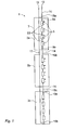
- FIG. 1 shows a modular energy storage device 1 for a high voltage electrical power system according to a first embodiment of the invention.
- High voltage electrical power systems can be networks for transmission or distribution of electrical energy as well as industries, hospitals and such.
- the same reference numerals are used throughout the figures for same or corresponding parts.
- the modular energy storage device includes two or more modules connected in series.
- the storage device 1 shown in figure 1 has three modules 3a-c. However, the number of module can be less or more than three.
- Each module 3a-c includes at least one dc power-source unit 5 enclosed in a container 7 and a positive 9a 10a and a negative 9b 10b terminal. The number of dc power-source units may vary.
- the device 1 further includes a positive 12 and a negative 11 pole, a first conductor 14 in the form of an insulated cable including a plurality of insulated cable parts 15a-c connected to the terminals 9a-b 10a-b of the modules 3a-c to provide a series connection of the modules 3a-c, and a second conductor 17 in the form of an insulated cable connected to the negative terminal 10b of the last module 3c in the series connection of modules 3a-c.
- the second conductor 17 can be connected to the positive terminal 9a of the first module 3a in the series connection of modules 3a-c.
- Series equipment devices such as switches (not shown) and dc power-source units 5 are connected in series with conductor parts 23 in the form of insulated cables thereby closing a current path between the positive 12 and negative 11 pole through the first 14 and second insulated cable 17.
- the first 14 and second 17 insulated cables are arranged to pass through the containers 7 in parallel such that a current flows through the first insulated cable 14 in a first direction and through the second insulated cable 17 in a second direction opposite to the first direction.
- High voltage insulated cables are suitable for this purpose.
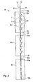
- FIG. 2 shows a modular energy storage device 40 for a high voltage electrical power system according to a second embodiment of the invention.
- the storage device 40 includes a first conductor 30 in the form of a conducting tube 30 which comprises a plurality of tube parts 16a-c connected to the terminals 9a-b 10a-b of the modules 4a-c to provide a series connection of the modules 4a-c, and a second conductor 17 connected to the negative terminal 10b of the last module 4c in the series connection of modules 4a-c.
- the second conductor 17 can be connected to the positive terminal 9a of the first module 3a in the series connection of modules 4a-c.
- the second conductor 17 is enclosed in the first conductor 30.
- the first tube 30 further comprises a plurality of tube parts 6 which interconnects the series equipment devices such as switches (not shown) and the dc power source units 5 thereby closing a current path between the positive 12 and negative 11 pole through the first 30 and second conductor 17.
- the first tube 30 and second conductor 17 are arranged to pass through the containers 7 in parallel such that a current flows through the first tube 30 in a first direction and through the second conductor 17 in a second direction opposite to the first direction.
- the second conductor 17 includes in one embodiment a metal tube. Suitable material for the tubes are copper, aluminium or the like. In another embodiment the second conductor 17 includes an insulated cable.
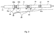
- Figure 3 shows a part of the first tube 30 and the second conductor 17 which is enclosed in the first tube 30.
- the figure shows the tube part 16a which connects the first module 4a to the positive pole (not shown in figure 3 ) and the tube part 16b which connects the first module 4a to the second module 4b. Between said tube parts 16a-b another tube part 6 is shown.
- This tube part 6 interconnects the series equipment devices such as switches and dc power source units 5 (not shown in figure 3 ) thereby closing the current path of the energy storage device.
- Tap-off devices 22a-b are used to connect the series equipment devices to the first tube 30.
- the tube part 16b which connects the first 4a and second 4b modules includes two tube parts 33-34 and the connector 21.
- the second conductor 17 is a metal tube and in another embodiment the second conductor 17 is a an insulated cable.
Landscapes
- Chemical & Material Sciences (AREA)
- Chemical Kinetics & Catalysis (AREA)
- Electrochemistry (AREA)
- General Chemical & Material Sciences (AREA)
- Engineering & Computer Science (AREA)
- Manufacturing & Machinery (AREA)
- Power Engineering (AREA)
- Inorganic Chemistry (AREA)
- Life Sciences & Earth Sciences (AREA)
- Sustainable Development (AREA)
- Sustainable Energy (AREA)
- Charge And Discharge Circuits For Batteries Or The Like (AREA)
Abstract
Description
- The present invention relates to a modular energy storage device for a high voltage electrical power system comprising at least one dc power-source unit enclosed in a container. By a high voltage electrical power system should be understood an electrical system within the range of 3 kV and upwards, preferably in the range of 10 kV and upwards. By energy storage device should be understood dc power source members connected in series to be within the range of 3 kV and upwards. One or more energy storage devices connected in parallel can for example be connected to the electrical power system via a power apparatus capable of controlling reactive power and/or active power. Examples of power apparatus are a power compensator and an uninterruptible power supply (UPS).
- Within flexible alternating current transmission systems (FACTS) a plurality of control apparatus are known. One such FACTS apparatus is a static compensator (STATCOM). A STATCOM comprises a voltage source converter (VSC) having an AC side connected to a high voltage electrical power system and a DC side connected to a temporary electric power storage means such as capacitors. The STATCOM can supply reactive power to or absorb reactive power from the transmission line.
- As opposed to the STATCOM, which only compensate for reactive power, another concept is to connect a dc power source to a compact STATCOM, and thus being able to perform active power compensation. The construction may be used e.g. as a spinning reserve and for compensating for fluctuating energy levels in the power system.
- Today the dc power source is a high voltage battery. Since the power apparatus is connected to the ac voltage of the high voltage electrical power system, a large number of battery cells have to be connected in series to match the dc voltage of the power apparatus. Moreover, to obtain a desired amount of electric energy (duration of active power) of the energy storage, a number of strings including a plurality of battery cells could be connected in parallel. The first conductor and the batteries themselves are typically placed at a distance to the second conductor. Since the conductors often consists of non-isolated metal bus bars this safe distance is important to prevent an accidental and contemporaneous contact of the conductors.
- Furthermore, in case of a fault, such as a short-circuit, the power apparatus has to be protected. Consequently, two switches are provided in each string to disconnect the string in case the converter, a string, or a part of the string is short-circuited. One switch is able to disconnect the string from the positive dc rail of the converter and the other switch is able to disconnect the string from the negative dc rail of the converter. Each of the switches has to be rated for the entire converter voltage to be capable of protecting the power apparatus.
- Up to now, mechanical dc circuit breakers have been used as switches for connection and disconnection of the strings. However, the availability of dc circuit breakers is limited and the ratings of these breakers are considerably low and less than the required voltage ratings in high voltage electrical power systems. To overcome this problem mechanical ac circuit breakers with some additional circuitry, such as a resonance circuit connected in parallel with the ac circuit breaker, have been used.
- A solid-state switch is an electronic switch that, unlike a mechanical breaker, contains no moving parts. There is a desire on the market to be able to exchange the mechanical ac circuit breakers with solid-state switches as proposed in
WO/2009/152849 where solid-state switches are distributed among the dc power-source units. However, high voltage power applications require large electric bus bar constructions that inevitably lead to high loop inductance. The loop inductance acts as a limiter of the current derivative (di/dt) during switching transitions. Since the turn-off of solid-state switches is much faster than the turn-off of mechanical breakers, large loop inductance implies high energy storage in the electric bus bar constructions and during fast interruption this energy will appear as a voltage spike across the switch (seeequation 1 & 2). This voltage spike will have fatal effects and destroy the switches.

- A known solution to reduce high voltage spikes across circuit breakers is to use additional equipment such as different kinds of snubber circuits and varistors connected to the breaker. Such additional equipment is however costly.
- It is an object of the invention to overcome or at least alleviate the above-mentioned problems. In particular, it is an object of the invention to provide an improved energy storage device for a high voltage electrical power system.
- According to one aspect of the invention this object is achieved by a modular energy storage device as defined in
claim 1. - The modular energy storage device for a high voltage electrical power system according to the invention is characterized in that it comprises at least two modules connected in series, each module including at least one dc power-source unit enclosed in a container and a positive and a negative terminal, and the device further comprising a positive and a negative pole, a first and a second conductor arranged to form a current path between the positive and negative poles, the first conductor including a plurality of conductor parts connected to the terminals of the modules to provide a series connection of the modules, a first module of the series connection of the modules being connected to one of the poles, and the second conductor is connected between a last module in the series connection of modules and the other pole, wherein the first and second conductors are arranged to pass through the containers in parallel such that a current flows through the first conductor in a first direction and through the second conductor in a second direction opposite to the first direction.
- An advantage with the modular energy storage device according to the invention is that by arranging the first and second conductor to pass through the containers in parallel, the distance between the conductors will be reduced leading to a reduced loop inductance and hence a reduced voltage spike will appear across the switch when the energy storage device is disconnected (see equation 2). As a result the rating of the disconnecting solid-state switch can be reduced. A further advantage is a minimised need for snubber circuits and varistors, the ratings of which at least can be significantly decreased. Additional advantages are that the energy storage device is compact, modular and has a flexible design.
- With a dc power-source unit is meant a plurality of series- and/or parallel-connected dc power source members. With a dc power source member is meant a small entity capable of providing dc power, such as a battery cell, a photovoltaic cell, a fuel cell, a flywheel or a super capacitor. Different types of dc power source members could also be combined in the dc power source.
- In an embodiment of the invention, at least one of the conductors comprises an insulated cable. An advantage with the use of an insulated cable is that electrical insulation of the conductor is automatically achieved. Hence the conductors can be placed with a very short distance to each other or even surface to surface in order to minimise the loop inductance of the energy storage device. Additionally, the insulation between the conductor and the container will be improved. A further advantage is that the degree of safety increases since the cable insulation prevents a person from having accidental contact with the conductor.
- In an embodiment of the invention both conductors comprise an insulated cable. An advantage with the use of insulated cables is that electrical insulation of the conductors is automatically achieved. Hence the conductors can be placed with a very short distance to each other or even surface to surface in order to minimise the loop inductance of the energy storage device. Moreover, the insulation between the conductors and the container will be improved. An additional advantage is that less isolation is required when both the conductors comprise an isolated cable.
- In an embodiment of the invention the first conductor comprises a metal tube, in the following denoted tube, surrounding the second conductor. For example, the second conductor is a cable. An advantage with this embodiment is that the loop inductance will be even smaller compared with parallel conductors. Accordingly, the snubber circuit ratings, the varistor ratings and the solid-state switch ratings can be further reduced. This embodiment also minimises the risk of module short-circuits due to the fact that the second conductor is enclosed by the first conductor. This solution also provides for an easy installation procedure where a standard insulated high voltage cable easily can be pushed through the tube to form the return path of the current.
- In an embodiment of the invention the second conductor comprises a second tube arranged with the envelope surface at a distance from the tube of the first conductor such that an electrical isolation is achieved between the tubes. One advantage with this embodiment is that the copper utilization is minimised.
- In an embodiment, each module provides DC voltage at 1-10 kV, preferably between 2 and 5 kV or approximately 3 kV. The energy storage device can be dimensioned for voltages between 10 kV and 100 kV, or even more than 100 kV. In an embodiment each battery unit provides between 50 and 1000 volts, such as more than 100 volts and/or lower than 500 volts, especially between 150 and 350 volts or approximately 250 volts. Twelve 250-volt battery units create a module voltage of 3 kV. Each module includes preferably more than three battery units, such as more than five or seven units, or more than ten units, such as twelve battery units or more.
- In an embodiment of the invention the distance between the envelope surfaces of the first and second conductor does not exceed 20 cm.
- One or more energy storage devices connected in parallel can for example be connected to the electrical power system via a power apparatus capable of controlling reactive power and/or active power. Examples of power apparatus are a power compensator and an uninterruptible power supply (UPS).
- The present invention will be more fully described by way of example with reference to the accompanying drawings in which:
-
Figure 1 shows a schematic figure of a first embodiment in accordance with the invention, -
Figure 2 shows a schematic figure of a second embodiment in accordance with the invention, -
Figure 3 shows a first and second conductor of the second embodiment in more detail. -
Figure 1 shows a modularenergy storage device 1 for a high voltage electrical power system according to a first embodiment of the invention. High voltage electrical power systems can be networks for transmission or distribution of electrical energy as well as industries, hospitals and such. The same reference numerals are used throughout the figures for same or corresponding parts. The modular energy storage device includes two or more modules connected in series. Thestorage device 1 shown infigure 1 has threemodules 3a-c. However, the number of module can be less or more than three. Eachmodule 3a-c includes at least one dc power-source unit 5 enclosed in a container 7 and apositive 9a 10a and anegative 9b 10b terminal. The number of dc power-source units may vary. Thedevice 1 further includes a positive 12 and a negative 11 pole, afirst conductor 14 in the form of an insulated cable including a plurality ofinsulated cable parts 15a-c connected to theterminals 9a-b 10a-b of themodules 3a-c to provide a series connection of themodules 3a-c, and asecond conductor 17 in the form of an insulated cable connected to thenegative terminal 10b of the last module 3c in the series connection ofmodules 3a-c. Alternatively, thesecond conductor 17 can be connected to thepositive terminal 9a of thefirst module 3a in the series connection ofmodules 3a-c. Series equipment devices such as switches (not shown) and dc power-source units 5 are connected in series withconductor parts 23 in the form of insulated cables thereby closing a current path between the positive 12 and negative 11 pole through the first 14 and secondinsulated cable 17. The first 14 and second 17 insulated cables are arranged to pass through the containers 7 in parallel such that a current flows through the firstinsulated cable 14 in a first direction and through the secondinsulated cable 17 in a second direction opposite to the first direction. High voltage insulated cables are suitable for this purpose. -
Figure 2 shows a modularenergy storage device 40 for a high voltage electrical power system according to a second embodiment of the invention. Thestorage device 40 includes afirst conductor 30 in the form of a conductingtube 30 which comprises a plurality of tube parts 16a-c connected to theterminals 9a-b 10a-b of themodules 4a-c to provide a series connection of themodules 4a-c, and asecond conductor 17 connected to thenegative terminal 10b of thelast module 4c in the series connection ofmodules 4a-c. Alternatively, thesecond conductor 17 can be connected to thepositive terminal 9a of thefirst module 3a in the series connection ofmodules 4a-c. Thesecond conductor 17 is enclosed in thefirst conductor 30. Thefirst tube 30 further comprises a plurality oftube parts 6 which interconnects the series equipment devices such as switches (not shown) and the dcpower source units 5 thereby closing a current path between the positive 12 and negative 11 pole through the first 30 andsecond conductor 17. Thefirst tube 30 andsecond conductor 17 are arranged to pass through the containers 7 in parallel such that a current flows through thefirst tube 30 in a first direction and through thesecond conductor 17 in a second direction opposite to the first direction. Thesecond conductor 17 includes in one embodiment a metal tube. Suitable material for the tubes are copper, aluminium or the like. In another embodiment thesecond conductor 17 includes an insulated cable. -
Figure 3 shows a part of thefirst tube 30 and thesecond conductor 17 which is enclosed in thefirst tube 30. The figure shows the tube part 16a which connects thefirst module 4a to the positive pole (not shown infigure 3 ) and thetube part 16b which connects thefirst module 4a to thesecond module 4b. Between said tube parts 16a-b anothertube part 6 is shown. Thistube part 6 interconnects the series equipment devices such as switches and dc power source units 5 (not shown infigure 3 ) thereby closing the current path of the energy storage device. There may beseveral tube parts 6 depending on the number of series equipment devices. Tap-offdevices 22a-b are used to connect the series equipment devices to thefirst tube 30. Between the two corresponding tap-offdevices 22a-b an insulatingspacer 20 of a non-conducting material is placed in order to not short-circuit the series equipment device. The series-connection of two modules is achieved by aconnector 21 of a conducting material such as copper or aluminium. Accordingly, thetube part 16b which connects the first 4a and second 4b modules includes two tube parts 33-34 and theconnector 21. In one embodiment thesecond conductor 17 is a metal tube and in another embodiment thesecond conductor 17 is a an insulated cable.
Claims (6)
- A modular energy storage device (1, 40) for a high voltage electrical power system comprising at least two modules (3a-c, 4a-c) connected in series, each module (3a-c, 4a-c) including at least one dc power-source unit (5) enclosed in a container (7) and a positive (9a, 10a) and a negative (9b, 10b) terminal, and the device further comprising a positive (12) and a negative (11) pole, a first (14, 30) and a second (17) conductor arranged to form a current path between the positive (9a, 10a) and negative (9b, 10b) poles, the first conductor (14, 30) including a plurality of conductor parts (23) connected to the terminals (9a-b, 10a-b) of the modules to provide a series connection of the modules (3a-c, 4a-c), a first module (3a, 3c, 4a, 4c) of the series connection of the modules being connected to one of the poles (11-12), and the second conductor (17) is connected between a last module (3c, 3a, 4c, 4a) in the series connection of modules and the other pole (11-12), characterized in that the first (14, 30) and second (17) conductors are arranged to pass through the containers (7) in parallel such that a current flows through the first conductor (14, 30) in a first direction and through the second conductor (17) in a second direction opposite to the first direction.
- The energy storage device according to claim 1, characterised in that the second conductor (17) comprises an insulated cable.
- The energy storage device according to claim 1 or 2, characterised in that the first conductor (14, 30) comprises an insulated cable.
- The energy storage device according to claim 1 or 2, characterised in that the first conductor (30) comprises a metal tube surrounding the second conductor.
- The energy storage device according to claim 4 characterised in that the second conductor (17) comprises a second metal tube arranged with the envelope surface at a distance from the metal tube of the first conductor (30) such that an electrical isolation is achieved between the tubes.
- The energy storage device according to any of claims 1-3, characterised in that the distance between the envelope surfaces of the first (14, 30) and second (17) conductor does not exceed 20 cm.
Priority Applications (1)
| Application Number | Priority Date | Filing Date | Title |
|---|---|---|---|
| EP10191561A EP2341598B1 (en) | 2009-12-30 | 2010-11-17 | A modular energy storage device for a high voltage electrical power system |
Applications Claiming Priority (2)
| Application Number | Priority Date | Filing Date | Title |
|---|---|---|---|
| PCT/EP2009/068038 WO2011079871A1 (en) | 2009-12-30 | 2009-12-30 | A modular energy storage device for a high voltage electrical power system |
| EP10191561A EP2341598B1 (en) | 2009-12-30 | 2010-11-17 | A modular energy storage device for a high voltage electrical power system |
Publications (2)
| Publication Number | Publication Date |
|---|---|
| EP2341598A1 true EP2341598A1 (en) | 2011-07-06 |
| EP2341598B1 EP2341598B1 (en) | 2012-07-25 |
Family
ID=42670435
Family Applications (1)
| Application Number | Title | Priority Date | Filing Date |
|---|---|---|---|
| EP10191561A Not-in-force EP2341598B1 (en) | 2009-12-30 | 2010-11-17 | A modular energy storage device for a high voltage electrical power system |
Country Status (6)
| Country | Link |
|---|---|
| US (1) | US8633614B2 (en) |
| EP (1) | EP2341598B1 (en) |
| KR (1) | KR20120099112A (en) |
| CN (1) | CN102118065B (en) |
| CA (1) | CA2721633A1 (en) |
| WO (1) | WO2011079871A1 (en) |
Families Citing this family (5)
| Publication number | Priority date | Publication date | Assignee | Title |
|---|---|---|---|---|
| US9331482B2 (en) | 2012-11-02 | 2016-05-03 | North Carolina State University | Static synchronous compensator systems and related methods |
| WO2014204649A1 (en) * | 2013-06-18 | 2014-12-24 | Rocketship, Inc. | Battery management system |
| WO2015024584A1 (en) * | 2013-08-20 | 2015-02-26 | Widex A/S | Hearing aid having a classifier |
| US12289850B2 (en) | 2021-02-12 | 2025-04-29 | Gary Barbosa | Modular electrical equipment storage assembly |
| KR102717209B1 (en) * | 2022-06-20 | 2024-10-15 | 주식회사 이랜텍 | Wire harness with variable number of connections |
Citations (3)
| Publication number | Priority date | Publication date | Assignee | Title |
|---|---|---|---|---|
| US5744936A (en) * | 1993-01-29 | 1998-04-28 | Canon Kabushiki Kaisha | Electric power accumulating apparatus and electric power system |
| US7304872B1 (en) * | 2004-09-24 | 2007-12-04 | Field Metrics, Inc. | Power supply |
| WO2009152849A1 (en) * | 2008-06-17 | 2009-12-23 | Abb Research Ltd | A power apparatus for a high voltage electrical power system |
Family Cites Families (1)
| Publication number | Priority date | Publication date | Assignee | Title |
|---|---|---|---|---|
| US20040201365A1 (en) * | 2001-04-05 | 2004-10-14 | Electrovaya Inc. | Energy storage device for loads having variable power rates |
-
2009
- 2009-12-30 WO PCT/EP2009/068038 patent/WO2011079871A1/en not_active Ceased
- 2009-12-30 KR KR1020127017100A patent/KR20120099112A/en not_active Abandoned
- 2009-12-30 CA CA2721633A patent/CA2721633A1/en not_active Abandoned
-
2010
- 2010-11-17 EP EP10191561A patent/EP2341598B1/en not_active Not-in-force
- 2010-11-22 US US12/951,906 patent/US8633614B2/en not_active Expired - Fee Related
- 2010-12-02 CN CN201010579971.8A patent/CN102118065B/en not_active Expired - Fee Related
Patent Citations (3)
| Publication number | Priority date | Publication date | Assignee | Title |
|---|---|---|---|---|
| US5744936A (en) * | 1993-01-29 | 1998-04-28 | Canon Kabushiki Kaisha | Electric power accumulating apparatus and electric power system |
| US7304872B1 (en) * | 2004-09-24 | 2007-12-04 | Field Metrics, Inc. | Power supply |
| WO2009152849A1 (en) * | 2008-06-17 | 2009-12-23 | Abb Research Ltd | A power apparatus for a high voltage electrical power system |
Also Published As
| Publication number | Publication date |
|---|---|
| CN102118065A (en) | 2011-07-06 |
| US8633614B2 (en) | 2014-01-21 |
| US20110159349A1 (en) | 2011-06-30 |
| KR20120099112A (en) | 2012-09-06 |
| EP2341598B1 (en) | 2012-07-25 |
| WO2011079871A1 (en) | 2011-07-07 |
| CN102118065B (en) | 2015-07-15 |
| CA2721633A1 (en) | 2011-06-30 |
Similar Documents
| Publication | Publication Date | Title |
|---|---|---|
| TWI508443B (en) | Method for controlling and supervising DC power supply and DC power supply for high-voltage power equipment and method of using DC power supply | |
| KR20100124829A (en) | Voltage source converter | |
| EP2341598B1 (en) | A modular energy storage device for a high voltage electrical power system | |
| EP3568914B1 (en) | Power supply system and method | |
| CN101258670A (en) | Device for electric energy transmission | |
| US8198750B2 (en) | Battery unit arrangement for high voltage applications, connector and disconnector arrangement and method | |
| CN115940114A (en) | A DC Power Supply System with Fixed Output Voltage | |
| EP3547472A1 (en) | Submodule | |
| US20220320870A1 (en) | Direct current power supply system, photovoltaic system, energy storage system, and optical storage system | |
| Deroualle et al. | Supercapacitors for enabling mechanical circuit breakers in shipboard zonal secondary dc-grids | |
| US20240405522A1 (en) | Solution preventing permanent deformation in an arc fault event or short circuit event | |
| Noritake et al. | Overcurrent protection for high voltage direct current (HVDC) distribution systems | |
| CN223181187U (en) | Be applied to many batteries in outdoor rack device that converges | |
| Soni et al. | Simulation analysis to investigate reasons for failure of neutral grounding reactor | |
| US20240282499A1 (en) | Transformer for data center | |
| EP4701041A1 (en) | Energy storage valve sub-module, energy storage valve, and energy storage station | |
| EP4657691A1 (en) | Electrical circuit and method for the connection of multiple dc sources to an electrical network | |
| US20240282513A1 (en) | Power supply system and power supply method for data center | |
| EP4672539A1 (en) | ENERGY STORAGE DEVICES FOR HIGH-VOLTAGE DC TRANSMISSION SYSTEMS (HVDC) | |
| Ding et al. | Design of a 12 MJ capacitor bank of the pulsed high magnetic field facility at HUST, Wuhan, China | |
| CN121693836A (en) | Converter system for an electric metal heating furnace system | |
| FI20225629A1 (en) | A power system construction |
Legal Events
| Date | Code | Title | Description |
|---|---|---|---|
| PUAI | Public reference made under article 153(3) epc to a published international application that has entered the european phase |
Free format text: ORIGINAL CODE: 0009012 |
|
| AK | Designated contracting states |
Kind code of ref document: A1 Designated state(s): AL AT BE BG CH CY CZ DE DK EE ES FI FR GB GR HR HU IE IS IT LI LT LU LV MC MK MT NL NO PL PT RO RS SE SI SK SM TR |
|
| AX | Request for extension of the european patent |
Extension state: BA ME |
|
| 17P | Request for examination filed |
Effective date: 20120109 |
|
| RIC1 | Information provided on ipc code assigned before grant |
Ipc: H02M 1/32 20070101ALI20120306BHEP Ipc: H02J 7/00 20060101AFI20120306BHEP |
|
| GRAP | Despatch of communication of intention to grant a patent |
Free format text: ORIGINAL CODE: EPIDOSNIGR1 |
|
| GRAS | Grant fee paid |
Free format text: ORIGINAL CODE: EPIDOSNIGR3 |
|
| GRAA | (expected) grant |
Free format text: ORIGINAL CODE: 0009210 |
|
| AK | Designated contracting states |
Kind code of ref document: B1 Designated state(s): AL AT BE BG CH CY CZ DE DK EE ES FI FR GB GR HR HU IE IS IT LI LT LU LV MC MK MT NL NO PL PT RO RS SE SI SK SM TR |
|
| REG | Reference to a national code |
Ref country code: GB Ref legal event code: FG4D |
|
| REG | Reference to a national code |
Ref country code: CH Ref legal event code: EP |
|
| REG | Reference to a national code |
Ref country code: AT Ref legal event code: REF Ref document number: 568042 Country of ref document: AT Kind code of ref document: T Effective date: 20120815 Ref country code: IE Ref legal event code: FG4D |
|
| REG | Reference to a national code |
Ref country code: DE Ref legal event code: R096 Ref document number: 602010002294 Country of ref document: DE Effective date: 20120920 |
|
| REG | Reference to a national code |
Ref country code: SE Ref legal event code: TRGR |
|
| REG | Reference to a national code |
Ref country code: NL Ref legal event code: VDEP Effective date: 20120725 |
|
| REG | Reference to a national code |
Ref country code: AT Ref legal event code: MK05 Ref document number: 568042 Country of ref document: AT Kind code of ref document: T Effective date: 20120725 |
|
| REG | Reference to a national code |
Ref country code: LT Ref legal event code: MG4D Effective date: 20120725 |
|
| PG25 | Lapsed in a contracting state [announced via postgrant information from national office to epo] |
Ref country code: NO Free format text: LAPSE BECAUSE OF FAILURE TO SUBMIT A TRANSLATION OF THE DESCRIPTION OR TO PAY THE FEE WITHIN THE PRESCRIBED TIME-LIMIT Effective date: 20121025 Ref country code: BE Free format text: LAPSE BECAUSE OF FAILURE TO SUBMIT A TRANSLATION OF THE DESCRIPTION OR TO PAY THE FEE WITHIN THE PRESCRIBED TIME-LIMIT Effective date: 20120725 Ref country code: HR Free format text: LAPSE BECAUSE OF FAILURE TO SUBMIT A TRANSLATION OF THE DESCRIPTION OR TO PAY THE FEE WITHIN THE PRESCRIBED TIME-LIMIT Effective date: 20120725 Ref country code: FI Free format text: LAPSE BECAUSE OF FAILURE TO SUBMIT A TRANSLATION OF THE DESCRIPTION OR TO PAY THE FEE WITHIN THE PRESCRIBED TIME-LIMIT Effective date: 20120725 Ref country code: IS Free format text: LAPSE BECAUSE OF FAILURE TO SUBMIT A TRANSLATION OF THE DESCRIPTION OR TO PAY THE FEE WITHIN THE PRESCRIBED TIME-LIMIT Effective date: 20121125 Ref country code: CY Free format text: LAPSE BECAUSE OF FAILURE TO SUBMIT A TRANSLATION OF THE DESCRIPTION OR TO PAY THE FEE WITHIN THE PRESCRIBED TIME-LIMIT Effective date: 20120725 Ref country code: LT Free format text: LAPSE BECAUSE OF FAILURE TO SUBMIT A TRANSLATION OF THE DESCRIPTION OR TO PAY THE FEE WITHIN THE PRESCRIBED TIME-LIMIT Effective date: 20120725 Ref country code: AT Free format text: LAPSE BECAUSE OF FAILURE TO SUBMIT A TRANSLATION OF THE DESCRIPTION OR TO PAY THE FEE WITHIN THE PRESCRIBED TIME-LIMIT Effective date: 20120725 |
|
| PG25 | Lapsed in a contracting state [announced via postgrant information from national office to epo] |
Ref country code: LV Free format text: LAPSE BECAUSE OF FAILURE TO SUBMIT A TRANSLATION OF THE DESCRIPTION OR TO PAY THE FEE WITHIN THE PRESCRIBED TIME-LIMIT Effective date: 20120725 Ref country code: SI Free format text: LAPSE BECAUSE OF FAILURE TO SUBMIT A TRANSLATION OF THE DESCRIPTION OR TO PAY THE FEE WITHIN THE PRESCRIBED TIME-LIMIT Effective date: 20120725 Ref country code: GR Free format text: LAPSE BECAUSE OF FAILURE TO SUBMIT A TRANSLATION OF THE DESCRIPTION OR TO PAY THE FEE WITHIN THE PRESCRIBED TIME-LIMIT Effective date: 20121026 Ref country code: PT Free format text: LAPSE BECAUSE OF FAILURE TO SUBMIT A TRANSLATION OF THE DESCRIPTION OR TO PAY THE FEE WITHIN THE PRESCRIBED TIME-LIMIT Effective date: 20121126 Ref country code: PL Free format text: LAPSE BECAUSE OF FAILURE TO SUBMIT A TRANSLATION OF THE DESCRIPTION OR TO PAY THE FEE WITHIN THE PRESCRIBED TIME-LIMIT Effective date: 20120725 |
|
| PG25 | Lapsed in a contracting state [announced via postgrant information from national office to epo] |
Ref country code: NL Free format text: LAPSE BECAUSE OF FAILURE TO SUBMIT A TRANSLATION OF THE DESCRIPTION OR TO PAY THE FEE WITHIN THE PRESCRIBED TIME-LIMIT Effective date: 20120725 |
|
| PG25 | Lapsed in a contracting state [announced via postgrant information from national office to epo] |
Ref country code: EE Free format text: LAPSE BECAUSE OF FAILURE TO SUBMIT A TRANSLATION OF THE DESCRIPTION OR TO PAY THE FEE WITHIN THE PRESCRIBED TIME-LIMIT Effective date: 20120725 Ref country code: RO Free format text: LAPSE BECAUSE OF FAILURE TO SUBMIT A TRANSLATION OF THE DESCRIPTION OR TO PAY THE FEE WITHIN THE PRESCRIBED TIME-LIMIT Effective date: 20120725 Ref country code: CZ Free format text: LAPSE BECAUSE OF FAILURE TO SUBMIT A TRANSLATION OF THE DESCRIPTION OR TO PAY THE FEE WITHIN THE PRESCRIBED TIME-LIMIT Effective date: 20120725 Ref country code: DK Free format text: LAPSE BECAUSE OF FAILURE TO SUBMIT A TRANSLATION OF THE DESCRIPTION OR TO PAY THE FEE WITHIN THE PRESCRIBED TIME-LIMIT Effective date: 20120725 |
|
| PG25 | Lapsed in a contracting state [announced via postgrant information from national office to epo] |
Ref country code: SK Free format text: LAPSE BECAUSE OF FAILURE TO SUBMIT A TRANSLATION OF THE DESCRIPTION OR TO PAY THE FEE WITHIN THE PRESCRIBED TIME-LIMIT Effective date: 20120725 Ref country code: IT Free format text: LAPSE BECAUSE OF FAILURE TO SUBMIT A TRANSLATION OF THE DESCRIPTION OR TO PAY THE FEE WITHIN THE PRESCRIBED TIME-LIMIT Effective date: 20120725 |
|
| PLBE | No opposition filed within time limit |
Free format text: ORIGINAL CODE: 0009261 |
|
| STAA | Information on the status of an ep patent application or granted ep patent |
Free format text: STATUS: NO OPPOSITION FILED WITHIN TIME LIMIT |
|
| 26N | No opposition filed |
Effective date: 20130426 |
|
| PG25 | Lapsed in a contracting state [announced via postgrant information from national office to epo] |
Ref country code: RS Free format text: LAPSE BECAUSE OF FAILURE TO SUBMIT A TRANSLATION OF THE DESCRIPTION OR TO PAY THE FEE WITHIN THE PRESCRIBED TIME-LIMIT Effective date: 20120725 Ref country code: BG Free format text: LAPSE BECAUSE OF FAILURE TO SUBMIT A TRANSLATION OF THE DESCRIPTION OR TO PAY THE FEE WITHIN THE PRESCRIBED TIME-LIMIT Effective date: 20121025 |
|
| REG | Reference to a national code |
Ref country code: IE Ref legal event code: MM4A |
|
| REG | Reference to a national code |
Ref country code: DE Ref legal event code: R097 Ref document number: 602010002294 Country of ref document: DE Effective date: 20130426 |
|
| PG25 | Lapsed in a contracting state [announced via postgrant information from national office to epo] |
Ref country code: IE Free format text: LAPSE BECAUSE OF NON-PAYMENT OF DUE FEES Effective date: 20121117 Ref country code: ES Free format text: LAPSE BECAUSE OF FAILURE TO SUBMIT A TRANSLATION OF THE DESCRIPTION OR TO PAY THE FEE WITHIN THE PRESCRIBED TIME-LIMIT Effective date: 20121105 |
|
| PG25 | Lapsed in a contracting state [announced via postgrant information from national office to epo] |
Ref country code: AL Free format text: LAPSE BECAUSE OF FAILURE TO SUBMIT A TRANSLATION OF THE DESCRIPTION OR TO PAY THE FEE WITHIN THE PRESCRIBED TIME-LIMIT Effective date: 20120725 Ref country code: MT Free format text: LAPSE BECAUSE OF FAILURE TO SUBMIT A TRANSLATION OF THE DESCRIPTION OR TO PAY THE FEE WITHIN THE PRESCRIBED TIME-LIMIT Effective date: 20120725 |
|
| PG25 | Lapsed in a contracting state [announced via postgrant information from national office to epo] |
Ref country code: TR Free format text: LAPSE BECAUSE OF FAILURE TO SUBMIT A TRANSLATION OF THE DESCRIPTION OR TO PAY THE FEE WITHIN THE PRESCRIBED TIME-LIMIT Effective date: 20120725 Ref country code: MC Free format text: LAPSE BECAUSE OF NON-PAYMENT OF DUE FEES Effective date: 20121130 |
|
| PG25 | Lapsed in a contracting state [announced via postgrant information from national office to epo] |
Ref country code: LU Free format text: LAPSE BECAUSE OF NON-PAYMENT OF DUE FEES Effective date: 20121117 Ref country code: SM Free format text: LAPSE BECAUSE OF FAILURE TO SUBMIT A TRANSLATION OF THE DESCRIPTION OR TO PAY THE FEE WITHIN THE PRESCRIBED TIME-LIMIT Effective date: 20120725 |
|
| PG25 | Lapsed in a contracting state [announced via postgrant information from national office to epo] |
Ref country code: HU Free format text: LAPSE BECAUSE OF FAILURE TO SUBMIT A TRANSLATION OF THE DESCRIPTION OR TO PAY THE FEE WITHIN THE PRESCRIBED TIME-LIMIT Effective date: 20101117 |
|
| PGFP | Annual fee paid to national office [announced via postgrant information from national office to epo] |
Ref country code: SE Payment date: 20141119 Year of fee payment: 5 Ref country code: GB Payment date: 20141119 Year of fee payment: 5 Ref country code: FR Payment date: 20141119 Year of fee payment: 5 Ref country code: DE Payment date: 20141119 Year of fee payment: 5 |
|
| REG | Reference to a national code |
Ref country code: CH Ref legal event code: PL |
|
| PG25 | Lapsed in a contracting state [announced via postgrant information from national office to epo] |
Ref country code: MK Free format text: LAPSE BECAUSE OF FAILURE TO SUBMIT A TRANSLATION OF THE DESCRIPTION OR TO PAY THE FEE WITHIN THE PRESCRIBED TIME-LIMIT Effective date: 20120725 Ref country code: CH Free format text: LAPSE BECAUSE OF NON-PAYMENT OF DUE FEES Effective date: 20141130 Ref country code: LI Free format text: LAPSE BECAUSE OF NON-PAYMENT OF DUE FEES Effective date: 20141130 |
|
| REG | Reference to a national code |
Ref country code: DE Ref legal event code: R119 Ref document number: 602010002294 Country of ref document: DE |
|
| GBPC | Gb: european patent ceased through non-payment of renewal fee |
Effective date: 20151117 |
|
| REG | Reference to a national code |
Ref country code: FR Ref legal event code: ST Effective date: 20160729 |
|
| PG25 | Lapsed in a contracting state [announced via postgrant information from national office to epo] |
Ref country code: SE Free format text: LAPSE BECAUSE OF NON-PAYMENT OF DUE FEES Effective date: 20151118 |
|
| PG25 | Lapsed in a contracting state [announced via postgrant information from national office to epo] |
Ref country code: DE Free format text: LAPSE BECAUSE OF NON-PAYMENT OF DUE FEES Effective date: 20160601 Ref country code: GB Free format text: LAPSE BECAUSE OF NON-PAYMENT OF DUE FEES Effective date: 20151117 |
|
| PG25 | Lapsed in a contracting state [announced via postgrant information from national office to epo] |
Ref country code: FR Free format text: LAPSE BECAUSE OF NON-PAYMENT OF DUE FEES Effective date: 20151130 |