EP2341444A1 - Data recording apparatus and method - Google Patents
Data recording apparatus and method Download PDFInfo
- Publication number
- EP2341444A1 EP2341444A1 EP10194139A EP10194139A EP2341444A1 EP 2341444 A1 EP2341444 A1 EP 2341444A1 EP 10194139 A EP10194139 A EP 10194139A EP 10194139 A EP10194139 A EP 10194139A EP 2341444 A1 EP2341444 A1 EP 2341444A1
- Authority
- EP
- European Patent Office
- Prior art keywords
- menu
- recording medium
- memory card
- detects
- function setting
- Prior art date
- Legal status (The legal status is an assumption and is not a legal conclusion. Google has not performed a legal analysis and makes no representation as to the accuracy of the status listed.)
- Granted
Links
Images


Classifications
-
- G—PHYSICS
- G11—INFORMATION STORAGE
- G11B—INFORMATION STORAGE BASED ON RELATIVE MOVEMENT BETWEEN RECORD CARRIER AND TRANSDUCER
- G11B20/00—Signal processing not specific to the method of recording or reproducing; Circuits therefor
- G11B20/10—Digital recording or reproducing
-
- G—PHYSICS
- G06—COMPUTING OR CALCULATING; COUNTING
- G06F—ELECTRIC DIGITAL DATA PROCESSING
- G06F13/00—Interconnection of, or transfer of information or other signals between, memories, input/output devices or central processing units
- G06F13/38—Information transfer, e.g. on bus
- G06F13/382—Information transfer, e.g. on bus using universal interface adapter
- G06F13/385—Information transfer, e.g. on bus using universal interface adapter for adaptation of a particular data processing system to different peripheral devices
-
- G—PHYSICS
- G06—COMPUTING OR CALCULATING; COUNTING
- G06F—ELECTRIC DIGITAL DATA PROCESSING
- G06F3/00—Input arrangements for transferring data to be processed into a form capable of being handled by the computer; Output arrangements for transferring data from processing unit to output unit, e.g. interface arrangements
- G06F3/01—Input arrangements or combined input and output arrangements for interaction between user and computer
- G06F3/048—Interaction techniques based on graphical user interfaces [GUI]
- G06F3/0481—Interaction techniques based on graphical user interfaces [GUI] based on specific properties of the displayed interaction object or a metaphor-based environment, e.g. interaction with desktop elements like windows or icons, or assisted by a cursor's changing behaviour or appearance
- G06F3/0482—Interaction with lists of selectable items, e.g. menus
-
- H—ELECTRICITY
- H04—ELECTRIC COMMUNICATION TECHNIQUE
- H04N—PICTORIAL COMMUNICATION, e.g. TELEVISION
- H04N5/00—Details of television systems
- H04N5/76—Television signal recording
- H04N5/765—Interface circuits between an apparatus for recording and another apparatus
- H04N5/77—Interface circuits between an apparatus for recording and another apparatus between a recording apparatus and a television camera
- H04N5/772—Interface circuits between an apparatus for recording and another apparatus between a recording apparatus and a television camera the recording apparatus and the television camera being placed in the same enclosure
Definitions
- the present invention relates to a data recording apparatus and method of recording information in a detachable(removable) recording medium such as a memory card.
- a semiconductor memory card is used as a recording medium for a digital camera.
- Many digital camera users transfer an image file obtained by image sensing from a memory card to a storage device such as the hard disk drive (HDD) of a personal computer (PC).
- HDD hard disk drive
- PC personal computer
- a memory card (to be referred to as a communication memory card hereinafter) having a wireless communication function is known to solve this problem.
- the communication memory cards include a memory card that automatically transfers, by wireless communication, image file that is obtained, to an external storage device designated in advance.
- Some communication memory cards start transmitting radio waves concurrently with attachment to a host device.
- wireless transmission is limited, for example, in a hospital, airplane, or region in which use of wireless devices is not authorized, it is necessary to prohibit wireless transmission before powering on the device.
- Japanese Patent Laid-Open No. 2007-311956 (to be referred to as patent reference 1 hereinafter) has proposed an invention to power on a portable communication terminal while simultaneously pressing a plurality of operation switches so as to limit wireless transmission from the terminal.
- the method of patent reference 1 requires the user to cumbersomely press the plurality of operation switches for each power-on.
- menu setting may prohibit wireless transmission from the memory card.
- an operation menu to disable wireless transmission needs to be operable even without card attachment.
- the operability may be poor for a user who uses no communication memory card. Contrivance is necessary for performing operations concerning the communication memory card while maintaining the menu operability in case of disuse of the communication memory card.
- any arrangement to solve the problems has not been proposed yet.
- a data recording apparatus capable of detachably attaching a storage medium having a predetermined function and a storage medium that does not have the predetermined function, and providing an operation menu concerning the predetermined function without loss of operability for a user, and a method thereof.
- the present invention in its first aspect provides a data recording apparatus as specified in claims 1 to 8.
- the present invention in its second aspect provides a data recording method as specified in claims 9 to 14.
- the present invention in its third aspect provides a computer program as specified in claim 15.
- a program can be provided by itself or carried by a carrier medium.
- the carrier medium may be a recording or other storage medium.
- the carrier medium may also be a transmission medium.
- the transmission medium may be a signal.
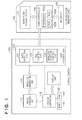
- Fig. 1 is a block diagram showing an example of the arrangement of a digital camera according to embodiments
- Figs. 2A to 2D are views for explaining a user interface switching timing according to the embodiments.
- Figs. 3A to 3D are views showing examples of user interface display according to the embodiments.
- Fig. 4 is a flowchart illustrating menu switching processing according to the first embodiment
- Fig. 5 is a flowchart illustrating menu switching processing according to the second embodiment
- Fig. 6 is a flowchart illustrating menu switching processing according to the third embodiment.
- Fig. 7 is a flowchart illustrating menu switching processing according to the fourth embodiment.
- a digital camera which controls the display state of a wireless function setting menu in accordance with the type information of an attached memory card.
- Fig. 1 is a block diagram showing an example of the arrangements of a digital camera 100 and a communication memory card 160 according to the first embodiment.
- the communication memory card 160 is attached to the digital camera 100 in the block diagram
- a general memory card without the automatic transfer function (to be referred to as a general memory card hereinafter) can also be attached to the digital camera 100. That is, the digital camera 100 has a memory slot capable of receiving a communication memory card or general memory card serving as a recording medium.
- An image sensing unit 110 includes an image sensor and an optical system (neither are shown). An optical image formed on the imaging plane of the image sensor via the optical system is converted into an electrical signal to obtain image data, thereby performing image sensing.
- An image file generation unit 120 generates an image file of the image sensed by the image sensing unit 110.
- a card control unit 130 writes the image file generated by the image file generation unit 120 in a memory card.
- a card detection unit 131 detects card attachment to the memory slot, and also transmits a command to obtain memory card information to the attached memory card so as to detect, based on received information, the type of attached card.
- the card control unit 130 also includes a file control unit 132 which controls a file to be generated for write in the memory card, and a wireless function control unit 133 which selectively validates or invalidates the wireless communication function when a communication memory card is attached.
- a system controller 140 is connected to a ROM 141 and a RAM 142, and executes various kinds of processing in the digital camera 100 in accordance with control programs stored in the ROM 141.
- a display unit 150 is formed from, for example, a liquid crystal display device and used to display various kinds of information such as system information, a reproduced image of a recorded image, and a menu concerning wireless function setting. The user can input various kinds of operations using an operation unit (not shown) and an operation menu displayed on the display unit 150 so as to transmit instructions to the system controller 140.
- the communication memory card 160 includes a NAND flash memory device 161, card controller 162, and RF circuit 163.
- the card controller 162 Upon receiving a write command from the card control unit 130 of the digital camera 100 serving as a host, the card controller 162 writes an image file in the NAND flash memory device 161 serving as a storage device.
- the card controller 162 also periodically monitors written files.
- the card controller 162 transfers the image file to an external storage device by wireless communication via the RF circuit 163.
- the card controller 162 includes a processor 162a, ROM 162b, and RAM 162c.
- the processor 162a executes various kinds of programs stored in the ROM 162b, thereby executing each processing in the communication memory card 160.
- control of the digital camera 100 may be done by a piece of hardware. Alternatively, a plurality of pieces of hardware may share the processing to control the entire apparatus. This also applies to control of the communication memory card 160.
- Fig. 2A is a view showing the switching timing of the wireless communication function setting menu display state according to the memory card attachment state in the digital camera of the first embodiment.
- the upper line of Fig. 2A indicates the state and type of a memory card attached to the card control unit 130, and the lower line indicates the display state of the wireless function setting menu in a menu list.
- the wireless function setting menu is set in a nondisplay state (before a timing 202).
- the nondisplay state e.g.
- a wireless function setting tab/menu is grayed out or deactivated), that is, the invalid state of the wireless function setting menu is maintained (the section between the timings 202 and 203). Even after the memory card is detached (timing 203), the nondisplay state of the wireless function setting menu is maintained, and the wireless function setting menu remains invalid (the section between the timings 203 and 204).
- the wireless function setting menu changes to the display state, that is, the valid state (the section between the timings 204 and 205). Even after the communication memory card 160 is detached (timing 205), the display state (valid state) of the wireless function setting menu is maintained (the section between the timings 205 and 206). Upon detecting attachment of a general memory card (timing 206), the wireless function setting menu changes to the nondisplay state again.
- Figs. 3A, 3B, and 3C are views showing examples of an operation menu according to the embodiment.
- an operation environment using the operation menu as shown in Figs. 3A to 3C is provided to the user.
- Fig. 3A is a view showing an example of menu display on the display unit 150 when the wireless function setting menu is not displayed.
- Fig. 3B is a view showing an example of menu display on the display unit 150 when a wireless function setting menu 301 is displayed.
- the wireless function setting menu changes to the display state, the wireless function setting menu 301 is added to the menu list displayed by selecting a tab 311, as shown in Fig. 3B .
- a window 302 to be used to switch the wireless function setting is displayed, as shown in Fig. 3C , so as to set "on/off" of the wireless function. If “off” is set on this window, the wireless function control unit 133 shifts to a mode to prohibit transmission of any radio wave from the communication memory card 160. Hence, the user who uses the digital camera and the communication memory card 160 in a place where wireless transmission is prohibited can set the wireless function to "off".
- Fig. 4 is a flowchart illustrating valid/invalid switching processing of the wireless function setting menu by the system controller 140.
- the card detection unit 131 Upon detecting attachment of a memory card (S401), the card detection unit 131 obtains type information of the memory card (S402). The system controller 140 determines based on the type information obtained by the card detection unit 131 whether the attached memory card is a communication memory card (S403). If it is a communication memory card, the system controller 140 validates the wireless function setting menu 301 (S404). If NO in step S403, the system controller 140 invalidates the wireless function setting menu 301 (S405).
- validating the wireless function setting menu 301 means that when the menu list is displayed by selecting the tab 311 or the like, the wireless function setting menu 301 is displayed so as to be selectable by a user operation. Invalidating the wireless function setting menu 301 means that when the menu list is displayed, the wireless function setting menu 301 is not displayed so as to be unselectable by a user operation. Note that in this embodiment, the menu is not displayed in the invalid state. However, the present invention is not limited to this. For example, the menu may be grayed out.
- the display state of the wireless function setting menu is switched in accordance with the type of attached memory card. Even when the memory card is detached, the display state of the wireless function setting menu is held. Note that a memory function of holding the menu state is provided in the wireless function control unit 133 and configured to be nonvolatile even when the system is powered off.
- the operation menu concerning wireless communication function setting is validated during the period of attachment of a recording medium (for example, communication memory card 160) having a wireless communication function is being detected.
- the operation menu concerning wireless communication function setting is invalidated on condition of not only the simple detached state of the recording medium with the wireless communication function but also detection of occurrence of a specific event. That is, the operation menu concerning wireless communication function setting changes to the nondisplay state when a predetermined event (in the first embodiment, attachment of a general memory card without the communication function) is detected in a state in which the recording medium having the wireless communication function is not attached.
- the display state of the wireless function setting menu is controlled in accordance with the type of previously attached memory card.
- the wireless function setting menu is displayed even when the memory card is temporarily detached.
- the wireless function setting menu is always nondisplayed, and the operability is prevented from being poor due to unnecessary menu display.
- the wireless function setting menu is not displayed only during a period a general memory card is attached.
- the arrangements of a digital camera 100 and a communication memory card 160 of the second embodiment are the same as in the first embodiment ( Fig. 1 ), and an illustration and description thereof will be omitted.
- Fig. 2B is a view showing the switching timing of the wireless communication function setting menu display state according to the memory card attachment state in the digital camera of the second embodiment.
- the upper line of Fig. 2B indicates the type of a memory card attached to a card control unit 130, and the lower line indicates the display state of the wireless function setting menu in a menu list.
- the wireless function setting menu is displayed in the initial state (before a timing 212).
- the wireless function setting menu changes to the nondisplay state (invalid state) (the section between the timings 212 and 213).
- the wireless function setting menu changes to the display state (valid state) (the section between the timings 213 and 214).
- the wireless function setting menu When attachment of the communication memory card 160 is detected (timing 214), the wireless function setting menu maintains the display state (valid state) (the section between the timings 214 and 215). Even after the communication memory card 160 is detached (timing 215), the display state (valid state) of the wireless function setting menu is maintained (the section between the timings 215 and 216). In the example shown in Fig. 2B , the wireless function setting menu is always displayed in the section between the timings 213 and 216. When a general memory card is attached, a wireless function setting menu 301 changes to the nondisplay state again (timing 216).
- Fig. 5 is a flowchart illustrating valid/invalid switching processing of the wireless function setting menu 301 by a system controller 140 according to the second embodiment.
- a card detection unit 131 Upon detecting attachment of a memory card (S501), a card detection unit 131 obtains type information of the memory card (S502). The system controller 140 determines based on the type information whether the attached memory card is a communication memory card (S503). Upon determining that it is a general memory card, the wireless function setting menu 301 is invalidated (S505). If card attachment is not detected, that is, a card detached state is detected in step S501, the system controller 140 validates the wireless function setting menu 301 (S507).
- step S503 the system controller 140 validates the wireless function setting menu 301 (S504). This is to cope with a situation that the general memory card is exchanged with the communication memory card 160 in a power-off state, and the digital camera 100 is then powered on.
- the period the wireless function setting menu is displayed in the second embodiment corresponds to the sum of the period defined in the first embodiment and the period the card detection unit 131 is detects the card detached state. That is, the wireless function setting menu is invalid only during the period a general memory card is attached.
- the memory function of holding the menu state during power-off is necessary. In the second embodiment, however, such a memory function is unnecessary.
- the wireless function setting menu is invalid, and the operability is prevented from being poor due to unnecessary menu display. If a user who uses a communication memory card moves to a place where the wireless function should be off, the valid state of the wireless function setting menu is maintained even after the memory card is detached. Hence, when the user changes the wireless function to off setting by the menu, and then attaches a communication memory card, it can be used as a simple memory card without transmitting any radio wave.
- the arrangement can also cope with a situation that the user wants to use a communication memory card as a simple memory card during use of a general memory card.
- the general memory card is detached for card exchange, and the wireless function setting menu is displayed at that point of time.
- the wireless function setting menu is displayed at that point of time.
- an explicit user instruction to invalidate a wireless function setting menu 301 is used as the above-described specific event. More specifically, in the third embodiment, until a communication memory card 160 is attached, the wireless function setting menu 301 is invalid. Once the communication memory card 160 is attached, the wireless function setting menu 301 is validated. When the wireless function setting menu 301 is valid, and no communication memory card is attached, an operation menu for returning the wireless function setting menu 301 to the nondisplay state is provided. Note that the arrangements of a digital camera 100 and the communication memory card 160 of the third embodiment are the same as in the first embodiment ( Fig. 1 ), and an illustration and description thereof will be omitted.
- Fig. 2C is a view showing the valid/invalid state switching timing of the communication function setting menu according to the memory card attachment state in the third embodiment.
- the upper line of Fig. 2C indicates the type of a memory card attached to a card control unit 130
- the intermediate line indicates the display state of the wireless function setting menu in a menu list
- the lower line indicates an erase menu display state upon selecting the wireless function setting menu.
- the wireless function setting menu 301 is not displayed (the section between timings 221 and 224).
- the wireless function setting menu is displayed.
- a wireless function setting menu erase menu 303 ( Fig. 3D ) is displayed, which serves as a menu for returning the wireless function setting menu 301 to the nondisplay state.
- Fig. 3B shows an example of menu display on a display unit 150 when the wireless function setting menu 301 is displayed.
- the wireless function setting menu 301 is displayed in the menu list, as shown in Fig. 3B .
- the operation window of the wireless function setting menu 301 includes the erase menu 303 to erase the wireless function setting menu 301. That is, when the user selects the wireless function setting menu 301 in Fig. 3B , a window for switching the setting ( Fig. 3D ) is presented to allow the user to select wireless function setting from "on/off/silent".
- the difference from Fig. 3C is that the erase menu 303 to instruct to erase the wireless function setting menu is added.
- the wireless function setting menu 301 is erased from the menu list so as to change the display to that in Fig. 3A .
- the window without the erase menu 303 is displayed, as shown in Fig. 3C .
- Fig. 6 is a flowchart illustrating valid/invalid switching processing of the wireless function setting menu 301 by the card control unit 130 and a system controller 140 according to the third embodiment.
- a card detection unit 131 Upon detecting attachment of a memory card (S601), a card detection unit 131 obtains type information of the memory card (S602). The system controller 140 determines based on the obtained type information whether the attached memory card is a communication memory card (S603). If it is a communication memory card, the wireless function setting menu 301 is validated (S604). Since the communication memory card is attached at this point of time, the system controller 140 invalidates the erase menu 303 to erase the wireless function setting menu 301 from the menu items (S608).
- the system controller 140 determines whether the wireless function setting menu 301 is valid (S606). If the wireless function setting menu 301 is invalid, the processing ends directly. On the other hand, upon determining in step S606 that the wireless function setting menu 301 is valid, the system controller 140 changes the above-described erase menu 303 to the valid state (S609). This allows to display the operation window additionally including the erase menu 303, as shown in Fig. 3D , when the user selects the wireless function setting menu 301. Upon detecting in this state that the user has selected the erase menu 303 (S610), the system controller 140 changes the wireless function setting menu 301 and the erase menu 303 to the invalid state (S611 and S612).
- the operation menu to erase the wireless function setting menu is invalidated and additionally displayed.
- the display state of the wireless function setting menu is switched in accordance with the type of attached memory card, as in the first embodiment. Even when the memory card is detached, the valid state of the wireless function setting menu is held.
- a memory function of holding information representing whether a communication memory card is attached is provided in a wireless function control unit 133 so that the stored contents are nonvolatile even when the system is powered off.
- the wireless function setting menu erase menu the state of the memory function is cleared to enable returning to the state before the communication memory card is attached for the first time.
- the wireless communication function setting menu is invalidated by the explicit user operation, a user-friendly user interface can be provided.
- a power-off operation is used as the above-described specific event. More specifically, in the fourth embodiment, a wireless function setting menu 301 is not displayed during a period after the system is powered on until a communication memory card 160 is attached. Once the communication memory card 160 is attached, the wireless function setting menu 301 maintains the display state until the system is powered off.
- the fourth embodiment is similar to the third embodiment, the implementation can be simplified because the menu display state needs not be held during the system power-off period.
- the block configuration is the same as that of the digital camera 100 of the first embodiment, and a description of the block diagram will not be repeated.
- Fig. 2D is a view showing the switching timing of the wireless communication function setting menu display state according to the type of memory card in a digital camera 100 of the fourth embodiment.
- the upper line of Fig. 2D indicates the type of a memory card attached to a card control unit 130
- the intermediate line indicates the display state of the wireless function setting menu 301 in a menu list
- the lower line indicates the power state of the system.
- the wireless function setting menu 301 is not displayed because no communication memory card is attached.
- the wireless function setting menu 301 maintains the nondisplay state (timings 232 and 233).
- the wireless function setting menu 301 is displayed. From then on, until the system is powered off (timing 237), the display state is maintained independently of the memory card attachment state (timings 234 to 237). When the system is powered off and then on next time, the wireless function setting menu 301 is not displayed (invalid) when executing initialization processing upon power-on (timing 238). Note that although not illustrated, when the power of the system changes from on to off (off to on) while the communication memory card is attached, the wireless function setting menu 301 is immediately displayed.
- Fig. 7 is a flowchart illustrating valid/invalid switching processing of the wireless function setting menu 301 by the card control unit 130 and a system controller 140 according to the fourth embodiment.
- the system controller 140 invalidates the wireless function setting menu 301 (S701, S702). Note that initialization processing is to be performed first after the system is powered off.
- a card detection unit 131 detects attachment of a memory card (S703), and obtains type information of the memory card (S704).
- the system controller 140 determines whether the attached memory card is a communication memory card (S705). If it is a communication memory card, the wireless function setting menu 301 is validated (S706).
- the processing ends.
- display of the wireless function setting menu starts at the timing of attachment of a communication memory card.
- Display of the wireless function setting menu ends at the execution timing of initialization processing upon powering on the system after power-off.
- the wireless function setting menu is not displayed before a communication memory card is attached for the first time.
- a communication memory card may be attached for the first time in a place where wireless transmission is prohibited.
- the system may be activated under a setting that prohibits wireless transmission by default (that is, automatically) if a communication memory card is attached in the nondisplay state of the wireless function setting menu.
- the system is preferably configured to immediately start the menu to enable the wireless communication function.
- one card slot is provided.
- the present invention is also applicable to a system having a plurality of card slots.
- the valid/invalid state of the wireless function setting menu is switched for each card slot, and the processing described in each embodiment is performed for each card slot.
- the determination in step S403 of the first embodiment is changed to "does any card slot have a communication memory card attached?" so as to generally determine the states of the plurality of card slots.
- the wireless function setting menu is validated.
- an independent wireless function setting menu may be provided for each card slot. This function is implemented by interpedently (independently) executing, for each card slot, the control associated with the wireless function setting menu of the above-described embodiments.
- a communication memory card having a communication function is applied as a first storage medium having a predetermined function
- a general memory card is applied as a second storage medium that does not have the predetermined function.
- the present invention is not limited to this.
- a memory card having a specific image processing function may be used as the first storage medium
- a memory card that does not have the specific image processing function may be used as the second storage medium.
- aspects of the present invention can also be realized by a computer of a system or apparatus (or devices such as a CPU or MPU) that reads out and executes a program recorded on a memory device to perform the functions of the above-described embodiment(s), and by a method, the steps of which are performed by a computer of a system or apparatus by, for example, reading out and executing a program recorded on a memory device to perform the functions of the above-described embodiment(s).
- the program is provided to the computer for example via a network or from a recording medium of various types serving as the memory device (for example, computer-readable storage medium).
Landscapes
- Engineering & Computer Science (AREA)
- Theoretical Computer Science (AREA)
- General Engineering & Computer Science (AREA)
- Signal Processing (AREA)
- Physics & Mathematics (AREA)
- General Physics & Mathematics (AREA)
- Multimedia (AREA)
- Human Computer Interaction (AREA)
- Studio Devices (AREA)
- Digital Computer Display Output (AREA)
- Television Signal Processing For Recording (AREA)
Abstract
Description
- The present invention relates to a data recording apparatus and method of recording information in a detachable(removable) recording medium such as a memory card.
- Generally, a semiconductor memory card is used as a recording medium for a digital camera. Many digital camera users transfer an image file obtained by image sensing from a memory card to a storage device such as the hard disk drive (HDD) of a personal computer (PC). However, this file transfer operation is cumbersome because it is attended with operations of connecting a cable and designating the storage destination directory every time. A memory card (to be referred to as a communication memory card hereinafter) having a wireless communication function is known to solve this problem. The communication memory cards include a memory card that automatically transfers, by wireless communication, image file that is obtained, to an external storage device designated in advance.
- Some communication memory cards start transmitting radio waves concurrently with attachment to a host device. However, where wireless transmission is limited, for example, in a hospital, airplane, or region in which use of wireless devices is not authorized, it is necessary to prohibit wireless transmission before powering on the device. To cope with this, Japanese Patent Laid-Open No.
2007-311956 patent reference 1 hereinafter) has proposed an invention to power on a portable communication terminal while simultaneously pressing a plurality of operation switches so as to limit wireless transmission from the terminal. - However, the method of
patent reference 1 requires the user to cumbersomely press the plurality of operation switches for each power-on. To prevent this, menu setting may prohibit wireless transmission from the memory card. In this case, to prohibit wireless transmission in advance, an operation menu to disable wireless transmission needs to be operable even without card attachment. On the other hand, if the menu concerning the communication memory card is always displayed, the operability may be poor for a user who uses no communication memory card. Contrivance is necessary for performing operations concerning the communication memory card while maintaining the menu operability in case of disuse of the communication memory card. However, any arrangement to solve the problems has not been proposed yet. - The present invention has been made in consideration of the above-described problems, and according to one aspect of the invention, there is provided a data recording apparatus capable of detachably attaching a storage medium having a predetermined function and a storage medium that does not have the predetermined function, and providing an operation menu concerning the predetermined function without loss of operability for a user, and a method thereof.
- The present invention in its first aspect provides a data recording apparatus as specified in
claims 1 to 8. - The present invention in its second aspect provides a data recording method as specified in claims 9 to 14.
- The present invention in its third aspect provides a computer program as specified in claim 15. Such a program can be provided by itself or carried by a carrier medium. The carrier medium may be a recording or other storage medium. The carrier medium may also be a transmission medium. The transmission medium may be a signal.
- Further features of the present invention will become apparent from the following description of exemplary embodiments with reference to the attached drawings.
-
Fig. 1 is a block diagram showing an example of the arrangement of a digital camera according to embodiments; -
Figs. 2A to 2D are views for explaining a user interface switching timing according to the embodiments; -
Figs. 3A to 3D are views showing examples of user interface display according to the embodiments; -
Fig. 4 is a flowchart illustrating menu switching processing according to the first embodiment; -
Fig. 5 is a flowchart illustrating menu switching processing according to the second embodiment; -
Fig. 6 is a flowchart illustrating menu switching processing according to the third embodiment; and -
Fig. 7 is a flowchart illustrating menu switching processing according to the fourth embodiment. - The embodiments will now be described in detail with reference to the accompanying drawings while exemplifying a digital camera as a recording apparatus according to the present invention.
- In the first embodiment, as a data recording apparatus for writing data in a detachable recording medium, a digital camera will be described, which controls the display state of a wireless function setting menu in accordance with the type information of an attached memory card.
-
Fig. 1 is a block diagram showing an example of the arrangements of adigital camera 100 and acommunication memory card 160 according to the first embodiment. Note that although thecommunication memory card 160 is attached to thedigital camera 100 in the block diagram, a general memory card without the automatic transfer function (to be referred to as a general memory card hereinafter) can also be attached to thedigital camera 100. That is, thedigital camera 100 has a memory slot capable of receiving a communication memory card or general memory card serving as a recording medium. - An
image sensing unit 110 includes an image sensor and an optical system (neither are shown). An optical image formed on the imaging plane of the image sensor via the optical system is converted into an electrical signal to obtain image data, thereby performing image sensing. An imagefile generation unit 120 generates an image file of the image sensed by theimage sensing unit 110. Acard control unit 130 writes the image file generated by the imagefile generation unit 120 in a memory card. In thecard control unit 130, acard detection unit 131 detects card attachment to the memory slot, and also transmits a command to obtain memory card information to the attached memory card so as to detect, based on received information, the type of attached card. Thecard control unit 130 also includes afile control unit 132 which controls a file to be generated for write in the memory card, and a wirelessfunction control unit 133 which selectively validates or invalidates the wireless communication function when a communication memory card is attached. - A
system controller 140 is connected to a ROM 141 and aRAM 142, and executes various kinds of processing in thedigital camera 100 in accordance with control programs stored in the ROM 141. Adisplay unit 150 is formed from, for example, a liquid crystal display device and used to display various kinds of information such as system information, a reproduced image of a recorded image, and a menu concerning wireless function setting. The user can input various kinds of operations using an operation unit (not shown) and an operation menu displayed on thedisplay unit 150 so as to transmit instructions to thesystem controller 140. - The
communication memory card 160 includes a NANDflash memory device 161,card controller 162, andRF circuit 163. Upon receiving a write command from thecard control unit 130 of thedigital camera 100 serving as a host, thecard controller 162 writes an image file in the NANDflash memory device 161 serving as a storage device. Thecard controller 162 also periodically monitors written files. Upon detecting image file write from thefile control unit 132, thecard controller 162 transfers the image file to an external storage device by wireless communication via theRF circuit 163. Note that thecard controller 162 includes aprocessor 162a,ROM 162b, andRAM 162c. Theprocessor 162a executes various kinds of programs stored in theROM 162b, thereby executing each processing in thecommunication memory card 160. - Note that control of the
digital camera 100 may be done by a piece of hardware. Alternatively, a plurality of pieces of hardware may share the processing to control the entire apparatus. This also applies to control of thecommunication memory card 160. -
Fig. 2A is a view showing the switching timing of the wireless communication function setting menu display state according to the memory card attachment state in the digital camera of the first embodiment. The upper line ofFig. 2A indicates the state and type of a memory card attached to thecard control unit 130, and the lower line indicates the display state of the wireless function setting menu in a menu list. Upon shipping the digital camera from the factory, the wireless function setting menu is set in a nondisplay state (before a timing 202). When thecard detection unit 131 detects attachment of a general memory card (timing 202), the nondisplay state (e.g. a wireless function setting tab/menu is grayed out or deactivated), that is, the invalid state of the wireless function setting menu is maintained (the section between thetimings 202 and 203). Even after the memory card is detached (timing 203), the nondisplay state of the wireless function setting menu is maintained, and the wireless function setting menu remains invalid (the section between thetimings 203 and 204). - When the
card detection unit 131 detects attachment of the communication memory card 160 (timing 204), the wireless function setting menu changes to the display state, that is, the valid state (the section between thetimings 204 and 205). Even after thecommunication memory card 160 is detached (timing 205), the display state (valid state) of the wireless function setting menu is maintained (the section between thetimings 205 and 206). Upon detecting attachment of a general memory card (timing 206), the wireless function setting menu changes to the nondisplay state again. -
Figs. 3A, 3B, and 3C are views showing examples of an operation menu according to the embodiment. In this embodiment, an operation environment using the operation menu as shown inFigs. 3A to 3C is provided to the user.Fig. 3A is a view showing an example of menu display on thedisplay unit 150 when the wireless function setting menu is not displayed.Fig. 3B is a view showing an example of menu display on thedisplay unit 150 when a wireless function setting menu 301 is displayed. When the wireless function setting menu changes to the display state, the wireless function setting menu 301 is added to the menu list displayed by selecting atab 311, as shown inFig. 3B . When the user selects the wireless function setting menu 301, awindow 302 to be used to switch the wireless function setting is displayed, as shown inFig. 3C , so as to set "on/off" of the wireless function. If "off" is set on this window, the wirelessfunction control unit 133 shifts to a mode to prohibit transmission of any radio wave from thecommunication memory card 160. Hence, the user who uses the digital camera and thecommunication memory card 160 in a place where wireless transmission is prohibited can set the wireless function to "off". -
Fig. 4 is a flowchart illustrating valid/invalid switching processing of the wireless function setting menu by thesystem controller 140. Upon detecting attachment of a memory card (S401), thecard detection unit 131 obtains type information of the memory card (S402). Thesystem controller 140 determines based on the type information obtained by thecard detection unit 131 whether the attached memory card is a communication memory card (S403). If it is a communication memory card, thesystem controller 140 validates the wireless function setting menu 301 (S404). If NO in step S403, thesystem controller 140 invalidates the wireless function setting menu 301 (S405). Note that validating the wireless function setting menu 301 means that when the menu list is displayed by selecting thetab 311 or the like, the wireless function setting menu 301 is displayed so as to be selectable by a user operation. Invalidating the wireless function setting menu 301 means that when the menu list is displayed, the wireless function setting menu 301 is not displayed so as to be unselectable by a user operation. Note that in this embodiment, the menu is not displayed in the invalid state. However, the present invention is not limited to this. For example, the menu may be grayed out. - As described above, in the first embodiment, the display state of the wireless function setting menu is switched in accordance with the type of attached memory card. Even when the memory card is detached, the display state of the wireless function setting menu is held. Note that a memory function of holding the menu state is provided in the wireless
function control unit 133 and configured to be nonvolatile even when the system is powered off. - As described above, in the first embodiment, the operation menu concerning wireless communication function setting is validated during the period of attachment of a recording medium (for example, communication memory card 160) having a wireless communication function is being detected. After validated, the operation menu concerning wireless communication function setting is invalidated on condition of not only the simple detached state of the recording medium with the wireless communication function but also detection of occurrence of a specific event. That is, the operation menu concerning wireless communication function setting changes to the nondisplay state when a predetermined event (in the first embodiment, attachment of a general memory card without the communication function) is detected in a state in which the recording medium having the wireless communication function is not attached.
- According to the above-described first embodiment, the display state of the wireless function setting menu is controlled in accordance with the type of previously attached memory card. Hence, if a user who uses a communication memory card moves to a place where the wireless function should be off, the wireless function setting menu is displayed even when the memory card is temporarily detached. When the user changes the wireless function to off setting by the menu, and then attaches a communication memory card, it can be used as a simple memory card without transmitting any radio wave. For a user who does not use a communication memory card, the wireless function setting menu is always nondisplayed, and the operability is prevented from being poor due to unnecessary menu display.
- In the second embodiment, an arrangement will be described, which not only performs valid/invalid switching of the wireless function setting menu according to the first embodiment but also displays (validates) the wireless function setting menu even upon detecting the detached state of a memory card. That is, in the second embodiment, the wireless function setting menu is not displayed only during a period a general memory card is attached. Note that the arrangements of a
digital camera 100 and acommunication memory card 160 of the second embodiment are the same as in the first embodiment (Fig. 1 ), and an illustration and description thereof will be omitted. -
Fig. 2B is a view showing the switching timing of the wireless communication function setting menu display state according to the memory card attachment state in the digital camera of the second embodiment. The upper line ofFig. 2B indicates the type of a memory card attached to acard control unit 130, and the lower line indicates the display state of the wireless function setting menu in a menu list. In the second embodiment, the wireless function setting menu is displayed in the initial state (before a timing 212). When attachment of a general memory card is detected (timing 212), the wireless function setting menu changes to the nondisplay state (invalid state) (the section between thetimings 212 and 213). When the memory card is detached, and the detached state of the memory card is detected (timing 213), the wireless function setting menu changes to the display state (valid state) (the section between the timings 213 and 214). - When attachment of the
communication memory card 160 is detected (timing 214), the wireless function setting menu maintains the display state (valid state) (the section between thetimings 214 and 215). Even after thecommunication memory card 160 is detached (timing 215), the display state (valid state) of the wireless function setting menu is maintained (the section between thetimings 215 and 216). In the example shown inFig. 2B , the wireless function setting menu is always displayed in the section between thetimings 213 and 216. When a general memory card is attached, a wireless function setting menu 301 changes to the nondisplay state again (timing 216). -
Fig. 5 is a flowchart illustrating valid/invalid switching processing of the wireless function setting menu 301 by asystem controller 140 according to the second embodiment. Upon detecting attachment of a memory card (S501), acard detection unit 131 obtains type information of the memory card (S502). Thesystem controller 140 determines based on the type information whether the attached memory card is a communication memory card (S503). Upon determining that it is a general memory card, the wireless function setting menu 301 is invalidated (S505). If card attachment is not detected, that is, a card detached state is detected in step S501, thesystem controller 140 validates the wireless function setting menu 301 (S507). Note that even when attachment of thecommunication memory card 160 is detected in step S503, thesystem controller 140 validates the wireless function setting menu 301 (S504). This is to cope with a situation that the general memory card is exchanged with thecommunication memory card 160 in a power-off state, and thedigital camera 100 is then powered on. - As described above, the period the wireless function setting menu is displayed in the second embodiment corresponds to the sum of the period defined in the first embodiment and the period the
card detection unit 131 is detects the card detached state. That is, the wireless function setting menu is invalid only during the period a general memory card is attached. In the first embodiment, the memory function of holding the menu state during power-off is necessary. In the second embodiment, however, such a memory function is unnecessary. - According to the above-described second embodiment, for a user who uses a general memory card, display of the wireless function setting menu is invalid, and the operability is prevented from being poor due to unnecessary menu display. If a user who uses a communication memory card moves to a place where the wireless function should be off, the valid state of the wireless function setting menu is maintained even after the memory card is detached. Hence, when the user changes the wireless function to off setting by the menu, and then attaches a communication memory card, it can be used as a simple memory card without transmitting any radio wave. The arrangement can also cope with a situation that the user wants to use a communication memory card as a simple memory card during use of a general memory card. In this case, the general memory card is detached for card exchange, and the wireless function setting menu is displayed at that point of time. Hence, when the user changes the wireless function to off setting, and then attaches a communication memory card, it can be used as a simple memory card without transmitting any radio wave.
- In the third embodiment, an explicit user instruction to invalidate a wireless function setting menu 301 is used as the above-described specific event. More specifically, in the third embodiment, until a
communication memory card 160 is attached, the wireless function setting menu 301 is invalid. Once thecommunication memory card 160 is attached, the wireless function setting menu 301 is validated. When the wireless function setting menu 301 is valid, and no communication memory card is attached, an operation menu for returning the wireless function setting menu 301 to the nondisplay state is provided. Note that the arrangements of adigital camera 100 and thecommunication memory card 160 of the third embodiment are the same as in the first embodiment (Fig. 1 ), and an illustration and description thereof will be omitted. -
Fig. 2C is a view showing the valid/invalid state switching timing of the communication function setting menu according to the memory card attachment state in the third embodiment. The upper line ofFig. 2C indicates the type of a memory card attached to acard control unit 130, the intermediate line indicates the display state of the wireless function setting menu in a menu list, and the lower line indicates an erase menu display state upon selecting the wireless function setting menu. - Until the
communication memory card 160 is attached (up to a timing 224), the wireless function setting menu 301 is not displayed (the section betweentimings 221 and 224). When thecommunication memory card 160 is attached (timing 224), the wireless function setting menu is displayed. When thecommunication memory card 160 is detached (timing 225), a wireless function setting menu erase menu 303 (Fig. 3D ) is displayed, which serves as a menu for returning the wireless function setting menu 301 to the nondisplay state. -
Fig. 3B shows an example of menu display on adisplay unit 150 when the wireless function setting menu 301 is displayed. Once thecommunication memory card 160 is attached, the wireless function setting menu 301 is displayed in the menu list, as shown inFig. 3B . When thecommunication memory card 160 is then detached, the operation window of the wireless function setting menu 301 includes the erasemenu 303 to erase the wireless function setting menu 301. That is, when the user selects the wireless function setting menu 301 inFig. 3B , a window for switching the setting (Fig. 3D ) is presented to allow the user to select wireless function setting from "on/off/silent". The difference fromFig. 3C is that the erasemenu 303 to instruct to erase the wireless function setting menu is added. When the user selects menu erase, the wireless function setting menu 301 is erased from the menu list so as to change the display to that inFig. 3A . Note that in this third embodiment, if the user selects the wireless function setting menu 301 while keeping the communication memory card attached, the window without the erasemenu 303 is displayed, as shown inFig. 3C . -
Fig. 6 is a flowchart illustrating valid/invalid switching processing of the wireless function setting menu 301 by thecard control unit 130 and asystem controller 140 according to the third embodiment. Upon detecting attachment of a memory card (S601), acard detection unit 131 obtains type information of the memory card (S602). Thesystem controller 140 determines based on the obtained type information whether the attached memory card is a communication memory card (S603). If it is a communication memory card, the wireless function setting menu 301 is validated (S604). Since the communication memory card is attached at this point of time, thesystem controller 140 invalidates the erasemenu 303 to erase the wireless function setting menu 301 from the menu items (S608). - If the attached memory card is a general memory card (NO in step S603), or no card is attached at all (NO in step S601), the
system controller 140 determines whether the wireless function setting menu 301 is valid (S606). If the wireless function setting menu 301 is invalid, the processing ends directly. On the other hand, upon determining in step S606 that the wireless function setting menu 301 is valid, thesystem controller 140 changes the above-described erasemenu 303 to the valid state (S609). This allows to display the operation window additionally including the erasemenu 303, as shown inFig. 3D , when the user selects the wireless function setting menu 301. Upon detecting in this state that the user has selected the erase menu 303 (S610), thesystem controller 140 changes the wireless function setting menu 301 and the erasemenu 303 to the invalid state (S611 and S612). - As described above, in the third embodiment, upon detecting the detached state of a communication memory card in the valid state of the wireless function setting menu, the operation menu to erase the wireless function setting menu is invalidated and additionally displayed. In the third embodiment, the display state of the wireless function setting menu is switched in accordance with the type of attached memory card, as in the first embodiment. Even when the memory card is detached, the valid state of the wireless function setting menu is held. Hence, a memory function of holding information representing whether a communication memory card is attached is provided in a wireless
function control unit 133 so that the stored contents are nonvolatile even when the system is powered off. When the user selects the wireless function setting menu erase menu, the state of the memory function is cleared to enable returning to the state before the communication memory card is attached for the first time. - According to the third embodiment, since the wireless communication function setting menu is invalidated by the explicit user operation, a user-friendly user interface can be provided.
- In the fourth embodiment, a power-off operation is used as the above-described specific event. More specifically, in the fourth embodiment, a wireless function setting menu 301 is not displayed during a period after the system is powered on until a
communication memory card 160 is attached. Once thecommunication memory card 160 is attached, the wireless function setting menu 301 maintains the display state until the system is powered off. Although the fourth embodiment is similar to the third embodiment, the implementation can be simplified because the menu display state needs not be held during the system power-off period. - In the fourth embodiment, the block configuration is the same as that of the
digital camera 100 of the first embodiment, and a description of the block diagram will not be repeated. -
Fig. 2D is a view showing the switching timing of the wireless communication function setting menu display state according to the type of memory card in adigital camera 100 of the fourth embodiment. The upper line ofFig. 2D indicates the type of a memory card attached to acard control unit 130, the intermediate line indicates the display state of the wireless function setting menu 301 in a menu list, and the lower line indicates the power state of the system. In the example shown inFig. 2D , when the system power changes from off to on (timing 231), the wireless function setting menu 301 is not displayed because no communication memory card is attached. Even when a general memory card is attached and detached, the wireless function setting menu 301 maintains the nondisplay state (timings 232 and 233). Once thecommunication memory card 160 is attached (timing 234), the wireless function setting menu 301 is displayed. From then on, until the system is powered off (timing 237), the display state is maintained independently of the memory card attachment state (timings 234 to 237). When the system is powered off and then on next time, the wireless function setting menu 301 is not displayed (invalid) when executing initialization processing upon power-on (timing 238). Note that although not illustrated, when the power of the system changes from on to off (off to on) while the communication memory card is attached, the wireless function setting menu 301 is immediately displayed. -
Fig. 7 is a flowchart illustrating valid/invalid switching processing of the wireless function setting menu 301 by thecard control unit 130 and asystem controller 140 according to the fourth embodiment. If initialization processing has not finished yet, thesystem controller 140 invalidates the wireless function setting menu 301 (S701, S702). Note that initialization processing is to be performed first after the system is powered off. When initialization processing has ended, acard detection unit 131 detects attachment of a memory card (S703), and obtains type information of the memory card (S704). Thesystem controller 140 determines whether the attached memory card is a communication memory card (S705). If it is a communication memory card, the wireless function setting menu 301 is validated (S706). On the other hand, upon determining that the attached memory card is a general memory card (NO in step S705), or card attachment is not detected (card detached state) (NO in step S703), the processing ends. - As described above, according to the fourth embodiment, display of the wireless function setting menu starts at the timing of attachment of a communication memory card. Display of the wireless function setting menu ends at the execution timing of initialization processing upon powering on the system after power-off.
- Note that in the first, third, and fourth embodiments, the wireless function setting menu is not displayed before a communication memory card is attached for the first time. A communication memory card may be attached for the first time in a place where wireless transmission is prohibited. To cope with such a scene, the system may be activated under a setting that prohibits wireless transmission by default (that is, automatically) if a communication memory card is attached in the nondisplay state of the wireless function setting menu. In this case, the system is preferably configured to immediately start the menu to enable the wireless communication function.
- Note that the above-described embodiments are mere examples of the present invention, and may be combined as needed.
- In the above-described embodiments, one card slot is provided. However, the present invention is also applicable to a system having a plurality of card slots. For example, the valid/invalid state of the wireless function setting menu is switched for each card slot, and the processing described in each embodiment is performed for each card slot. Alternatively, for example, the determination in step S403 of the first embodiment is changed to "does any card slot have a communication memory card attached?" so as to generally determine the states of the plurality of card slots. In this case, if at least one card slot has a communication memory card attached to it, the wireless function setting menu is validated. Otherwise, an independent wireless function setting menu may be provided for each card slot. This function is implemented by interpedently (independently) executing, for each card slot, the control associated with the wireless function setting menu of the above-described embodiments.
- As described above, according to the embodiments, it is possible to display the menu concerning the communication memory card without degrading the operability for the user.
- Note that in the above-described embodiments, a communication memory card having a communication function is applied as a first storage medium having a predetermined function, and a general memory card is applied as a second storage medium that does not have the predetermined function. However, the present invention is not limited to this. For example, a memory card having a specific image processing function may be used as the first storage medium, and a memory card that does not have the specific image processing function may be used as the second storage medium.
- Aspects of the present invention can also be realized by a computer of a system or apparatus (or devices such as a CPU or MPU) that reads out and executes a program recorded on a memory device to perform the functions of the above-described embodiment(s), and by a method, the steps of which are performed by a computer of a system or apparatus by, for example, reading out and executing a program recorded on a memory device to perform the functions of the above-described embodiment(s). For this purpose, the program is provided to the computer for example via a network or from a recording medium of various types serving as the memory device (for example, computer-readable storage medium).
- While the present invention has been described with reference to exemplary embodiments, it is to be understood that the invention is not limited to the disclosed exemplary embodiments. The scope of the following claims is to be accorded the broadest interpretation so as to encompass all such modifications and equivalent structures and functions.
Claims (15)
- A data recording apparatus (100) comprising:connection means (130) for connecting a recording medium, wherein the connection means is capable of connecting, as the recording medium, a first recording medium (160) having a predetermined function and a second recording medium that does not have the predetermined function;detection means (131) for detecting a connection status of the recording medium to the connection means; andcontrol means (140) for controlling a menu concerning setting of the predetermined function,wherein said control means (140) is configured, when said detection means detects (Fig. 2A) that the first recording medium (160) is connected to said connection means (130) or when said detection means detects (Fig. 2B) that the second recording medium is not connected to said connection means (130), to make the menu operable,wherein said control means (140) is configured, when the detection means detects that the first recording medium (160) is removed and then detects that a predetermined event has occurred, to make the menu inoperable, andwherein said control means is configured to maintain the menu in the operable state during a period from removal of the first recording medium (160) to detection of the predetermined event.
- The apparatus according to claim 1, wherein the predetermined event is connection of the second recording medium to the connection means, and wherein the control means is configured, when the detection means detects that the first recording medium is removed and then detects that the second recording medium is connected to said connection means as the predetermined event, to make the menu inoperable, and
wherein said control means is configured to maintain the menu in the operable state during a period from removal of the first recording medium to connection of the second recording medium to said connection means (Fig. 2B). - The apparatus according to claim 1, wherein the predetermined event is a user instruction to make the menu inoperable, and wherein the control means is configured, when the detection means detects that the first recording medium is removed and then detects the user instruction to make the menu inoperable as the predetermined event, to make the menu inoperable, and
wherein said control means is configured to maintain the menu in the operable state during a period from removal of the first recording medium to receipt of the user instruction to make the menu inoperable (Fig. 2C). - The apparatus according to claim 1, wherein the predetermined event is an apparatus power-off instruction, and wherein the control means is configured, when the detection means detects that the first recording medium is removed and then detects the apparatus power-off instruction as the predetermined event, to make the menu inoperable, and
wherein said control means is configured to maintain the menu in the operable state during a period from removal of the first recording medium to issuance of the apparatus power-off instruction (Fig. 2D). - The apparatus according to any preceding claim, further comprising a plurality of connection means, and
wherein said control means is configured to independently control a menu corresponding to each of said plurality of connection means. - The apparatus according to claim 1 or claim 2, wherein said control means is configured, if said detection means detects that the first recording medium (60) is removed and then detects that the second recording medium is connected to said connection means, to make the menu inoperable by graying out the menu.
- The apparatus according to claim 1 or claim 2, wherein said control means is configured, if said detection means detects that the first recording medium is removed and then detects that the second recording medium is connected to said connection means, to make the menu inoperable by setting the menu in a non-display state.
- The apparatus according to any preceding claim, wherein
the first recording medium (160) comprises wireless communication means, and
the predetermined function is a wireless communication function of the wireless communication means. - A method of controlling a data recording apparatus (100) including a connection means (130) configured to connect a recording medium, wherein the connection means is capable of connecting, as the recording medium, a first recording medium (160) having a predetermined function and a second recording medium that does not have the predetermined function, the method comprising the steps of:detecting (S401) a connection status of the recording medium to the connection means; andcontrolling a menu concerning setting of the predetermined function,wherein in the step of controlling the menu,
if the detecting step detects that the first recording medium (16) is connected to the connection means, the menu is made operable (S404),
if the detecting step detects that the first recording medium (160) is removed and then detects that a predetermined event has occurred, the menu is made inoperable (S405), and
the menu is maintained in the operable state during a period from removal of the first recording medium (160) to detection of the predetermined event. - The method of according to claim 9, wherein the predetermined event is any one of: connection of the second recording medium to the connection means, a user instruction to make the menu inoperable, and an apparatus power-off instruction.
- The method according to claim 9 or claim 10, wherein the data recording apparatus further includes a plurality of connection means, and
wherein the step of controlling the menu comprising controlling independently a menu corresponding to each of the plurality of connection means. - The method according to claim 9, wherein in the step of controlling the menu, if the detecting step detects that the first recording medium is removed and then detects that the second recording medium is connected to the connection means, control is performed to make the menu inoperable by graying out the menu.
- The method according to claim 9, wherein in the step of controlling the menu, if the detecting step detects that the first recording medium is removed and then detecting that the second recording medium is connected to the connection means, control is performed to make the menu inoperable by setting the menu in a non-display state.
- The method according to any one of claims 9 to 13, wherein
the first recording medium (160) includes wireless communication means, and
the predetermined function is a wireless communication function of the wireless communication means. - A computer-executable program which, when executed by a computer, causes the computer to carry out the method according to any one of claims 9 to 14.
Applications Claiming Priority (1)
| Application Number | Priority Date | Filing Date | Title |
|---|---|---|---|
| JP2009286963A JP5361695B2 (en) | 2009-12-17 | 2009-12-17 | Data recording apparatus and control method thereof |
Publications (2)
| Publication Number | Publication Date |
|---|---|
| EP2341444A1 true EP2341444A1 (en) | 2011-07-06 |
| EP2341444B1 EP2341444B1 (en) | 2013-08-07 |
Family
ID=43754705
Family Applications (1)
| Application Number | Title | Priority Date | Filing Date |
|---|---|---|---|
| EP10194139.1A Not-in-force EP2341444B1 (en) | 2009-12-17 | 2010-12-08 | Data recording apparatus and method |
Country Status (5)
| Country | Link |
|---|---|
| US (3) | US8225010B2 (en) |
| EP (1) | EP2341444B1 (en) |
| JP (1) | JP5361695B2 (en) |
| KR (1) | KR20110069703A (en) |
| CN (1) | CN102157172B (en) |
Families Citing this family (13)
| Publication number | Priority date | Publication date | Assignee | Title |
|---|---|---|---|---|
| JP2013025485A (en) * | 2011-07-19 | 2013-02-04 | Toshiba Corp | Semiconductor storage device |
| JP5762197B2 (en) * | 2011-07-27 | 2015-08-12 | キヤノン株式会社 | IMAGING DEVICE, ITS CONTROL METHOD, PROGRAM, AND STORAGE MEDIUM |
| US8386691B1 (en) * | 2011-08-19 | 2013-02-26 | Key Asic Inc. | Multimedia storage card system |
| JP5972115B2 (en) * | 2012-09-03 | 2016-08-17 | キヤノン株式会社 | Imaging apparatus, control method thereof, and program |
| JP6115127B2 (en) * | 2012-12-27 | 2017-04-19 | リコーイメージング株式会社 | Communication system for digital cameras and portable devices |
| JP6174868B2 (en) * | 2013-02-27 | 2017-08-02 | キヤノン株式会社 | Electronic device and control method thereof |
| JP6655875B2 (en) | 2014-12-22 | 2020-03-04 | キヤノン株式会社 | Data recording device, control method therefor, and program |
| JP6995607B2 (en) * | 2017-12-19 | 2022-01-14 | キヤノン株式会社 | Information processing equipment, control methods and programs for information processing equipment |
| JP7238087B2 (en) * | 2017-12-19 | 2023-03-13 | キヤノン株式会社 | JOB PROCESSING DEVICE, CONTROL METHOD AND PROGRAM FOR JOB PROCESSING DEVICE |
| JP6669216B2 (en) * | 2018-08-30 | 2020-03-18 | 株式会社Jvcケンウッド | Electronic equipment, operation method, program |
| JP2020149332A (en) * | 2019-03-13 | 2020-09-17 | 株式会社サテライトオフィス | Security browser application software |
| JP7482649B2 (en) * | 2020-02-28 | 2024-05-14 | キヤノン株式会社 | Imaging apparatus, device, control method, and program |
| JP2022068663A (en) * | 2020-10-22 | 2022-05-10 | キヤノン株式会社 | Imaging apparatus, information processing method, and program |
Citations (2)
| Publication number | Priority date | Publication date | Assignee | Title |
|---|---|---|---|---|
| EP1187450A2 (en) * | 2000-09-12 | 2002-03-13 | Canon Kabushiki Kaisha | Image pickup apparatus |
| JP2007311956A (en) | 2006-05-17 | 2007-11-29 | Nec Corp | Mobile communication terminal |
Family Cites Families (3)
| Publication number | Priority date | Publication date | Assignee | Title |
|---|---|---|---|---|
| JP4576553B2 (en) * | 2003-12-19 | 2010-11-10 | カシオ計算機株式会社 | Electronic dictionary device and electronic dictionary control program |
| US7930501B2 (en) * | 2004-04-23 | 2011-04-19 | Panasonic Corporation | Memory card, access device, and processing method of memory card |
| JP5304458B2 (en) * | 2009-06-11 | 2013-10-02 | 株式会社ニコン | Electronic camera |
-
2009
- 2009-12-17 JP JP2009286963A patent/JP5361695B2/en not_active Expired - Fee Related
-
2010
- 2010-12-02 KR KR1020100121774A patent/KR20110069703A/en not_active Ceased
- 2010-12-03 US US12/959,520 patent/US8225010B2/en not_active Expired - Fee Related
- 2010-12-08 EP EP10194139.1A patent/EP2341444B1/en not_active Not-in-force
- 2010-12-16 CN CN201010600082.5A patent/CN102157172B/en not_active Expired - Fee Related
-
2012
- 2012-06-15 US US13/524,801 patent/US8380890B2/en not_active Expired - Fee Related
-
2013
- 2013-01-23 US US13/747,837 patent/US8533371B2/en not_active Expired - Fee Related
Patent Citations (2)
| Publication number | Priority date | Publication date | Assignee | Title |
|---|---|---|---|---|
| EP1187450A2 (en) * | 2000-09-12 | 2002-03-13 | Canon Kabushiki Kaisha | Image pickup apparatus |
| JP2007311956A (en) | 2006-05-17 | 2007-11-29 | Nec Corp | Mobile communication terminal |
Non-Patent Citations (1)
| Title |
|---|
| ROB GALBRAITH: "Eye-Fi Collaborates with Nikon to introduce the 'EYE-FI Connected' NIKON D90 Digital SLR Camera", 27 August 2008 (2008-08-27), XP002629999, Retrieved from the Internet <URL:http://www.robgalbraith.com/bins/content_page.asp?cid=7-9314-9577> [retrieved on 20110325] * |
Also Published As
| Publication number | Publication date |
|---|---|
| US8380890B2 (en) | 2013-02-19 |
| US20130135497A1 (en) | 2013-05-30 |
| US8533371B2 (en) | 2013-09-10 |
| JP5361695B2 (en) | 2013-12-04 |
| CN102157172A (en) | 2011-08-17 |
| EP2341444B1 (en) | 2013-08-07 |
| US20110153874A1 (en) | 2011-06-23 |
| JP2011128910A (en) | 2011-06-30 |
| US8225010B2 (en) | 2012-07-17 |
| US20120260003A1 (en) | 2012-10-11 |
| CN102157172B (en) | 2015-03-04 |
| KR20110069703A (en) | 2011-06-23 |
Similar Documents
| Publication | Publication Date | Title |
|---|---|---|
| EP2341444B1 (en) | Data recording apparatus and method | |
| RU2628269C2 (en) | Device for information processing, method of controlling information processing device and data media | |
| US9203993B2 (en) | Display system and electronic device | |
| EP2894570B1 (en) | Information processing apparatus that suppresses power consumption and method for controlling the same, and storage medium | |
| JP5495762B2 (en) | Data processing apparatus and control method thereof | |
| JP2005184208A (en) | Image processing device | |
| JP2017104999A (en) | Information processing device, method for controlling the same and program | |
| US20160004482A1 (en) | Printing system, image processing apparatus, information processing apparatus, information processing method, and program | |
| US11122182B2 (en) | Information processing apparatus, storage medium, and control method with voice instruction to peform print settings operation | |
| JP2000137796A (en) | Information input system, control method thereof, and storage medium | |
| EP3995946A1 (en) | Information processing apparatus, method for controlling information processing, and storage medium | |
| JP5055098B2 (en) | Image display system, information processing apparatus, control method thereof, and program | |
| JP6366271B2 (en) | Information processing apparatus and control method of information processing apparatus | |
| JP2001142618A (en) | Image processing apparatus, method, storage medium and program element | |
| JP2004040370A (en) | Image processing apparatus, control method therefor, program and storage medium | |
| JP7191899B2 (en) | Information processing device and its control method | |
| US7644195B2 (en) | Host connectable device capable of selecting mode using menu displayed automatically upon connecting to host device and method thereof | |
| KR101446940B1 (en) | Digital image processing apparatus comprising the function of determining the class of USB host and the communicating method of the same | |
| JP2007034614A (en) | COMMUNICATION DEVICE AND ITS CONTROL METHOD | |
| JP2010009121A (en) | Data controller, control method, and program | |
| JP5619312B2 (en) | Data processing apparatus and control method thereof | |
| JP2007148930A (en) | Electronic device, electronic device control method, and computer program | |
| JP2004355135A (en) | Information processing device | |
| KR100594592B1 (en) | How to transfer video data of mobile communication terminal to USB drive | |
| JP2026028587A (en) | Electronic device, electronic device control method, and electronic device control program |
Legal Events
| Date | Code | Title | Description |
|---|---|---|---|
| PUAI | Public reference made under article 153(3) epc to a published international application that has entered the european phase |
Free format text: ORIGINAL CODE: 0009012 |
|
| AK | Designated contracting states |
Kind code of ref document: A1 Designated state(s): AL AT BE BG CH CY CZ DE DK EE ES FI FR GB GR HR HU IE IS IT LI LT LU LV MC MK MT NL NO PL PT RO RS SE SI SK SM TR |
|
| AX | Request for extension of the european patent |
Extension state: BA ME |
|
| 17P | Request for examination filed |
Effective date: 20120109 |
|
| GRAP | Despatch of communication of intention to grant a patent |
Free format text: ORIGINAL CODE: EPIDOSNIGR1 |
|
| GRAS | Grant fee paid |
Free format text: ORIGINAL CODE: EPIDOSNIGR3 |
|
| GRAA | (expected) grant |
Free format text: ORIGINAL CODE: 0009210 |
|
| AK | Designated contracting states |
Kind code of ref document: B1 Designated state(s): AL AT BE BG CH CY CZ DE DK EE ES FI FR GB GR HR HU IE IS IT LI LT LU LV MC MK MT NL NO PL PT RO RS SE SI SK SM TR |
|
| REG | Reference to a national code |
Ref country code: GB Ref legal event code: FG4D |
|
| REG | Reference to a national code |
Ref country code: AT Ref legal event code: REF Ref document number: 626031 Country of ref document: AT Kind code of ref document: T Effective date: 20130815 Ref country code: CH Ref legal event code: EP |
|
| REG | Reference to a national code |
Ref country code: IE Ref legal event code: FG4D |
|
| REG | Reference to a national code |
Ref country code: DE Ref legal event code: R096 Ref document number: 602010009167 Country of ref document: DE Effective date: 20131002 |
|
| REG | Reference to a national code |
Ref country code: AT Ref legal event code: MK05 Ref document number: 626031 Country of ref document: AT Kind code of ref document: T Effective date: 20130807 |
|
| REG | Reference to a national code |
Ref country code: NL Ref legal event code: VDEP Effective date: 20130807 |
|
| REG | Reference to a national code |
Ref country code: LT Ref legal event code: MG4D |
|
| PG25 | Lapsed in a contracting state [announced via postgrant information from national office to epo] |
Ref country code: PT Free format text: LAPSE BECAUSE OF FAILURE TO SUBMIT A TRANSLATION OF THE DESCRIPTION OR TO PAY THE FEE WITHIN THE PRESCRIBED TIME-LIMIT Effective date: 20131209 Ref country code: AT Free format text: LAPSE BECAUSE OF FAILURE TO SUBMIT A TRANSLATION OF THE DESCRIPTION OR TO PAY THE FEE WITHIN THE PRESCRIBED TIME-LIMIT Effective date: 20130807 Ref country code: NO Free format text: LAPSE BECAUSE OF FAILURE TO SUBMIT A TRANSLATION OF THE DESCRIPTION OR TO PAY THE FEE WITHIN THE PRESCRIBED TIME-LIMIT Effective date: 20131107 Ref country code: HR Free format text: LAPSE BECAUSE OF FAILURE TO SUBMIT A TRANSLATION OF THE DESCRIPTION OR TO PAY THE FEE WITHIN THE PRESCRIBED TIME-LIMIT Effective date: 20130807 Ref country code: SE Free format text: LAPSE BECAUSE OF FAILURE TO SUBMIT A TRANSLATION OF THE DESCRIPTION OR TO PAY THE FEE WITHIN THE PRESCRIBED TIME-LIMIT Effective date: 20130807 Ref country code: LT Free format text: LAPSE BECAUSE OF FAILURE TO SUBMIT A TRANSLATION OF THE DESCRIPTION OR TO PAY THE FEE WITHIN THE PRESCRIBED TIME-LIMIT Effective date: 20130807 Ref country code: IS Free format text: LAPSE BECAUSE OF FAILURE TO SUBMIT A TRANSLATION OF THE DESCRIPTION OR TO PAY THE FEE WITHIN THE PRESCRIBED TIME-LIMIT Effective date: 20131207 Ref country code: CY Free format text: LAPSE BECAUSE OF FAILURE TO SUBMIT A TRANSLATION OF THE DESCRIPTION OR TO PAY THE FEE WITHIN THE PRESCRIBED TIME-LIMIT Effective date: 20130724 |
|
| PG25 | Lapsed in a contracting state [announced via postgrant information from national office to epo] |
Ref country code: GR Free format text: LAPSE BECAUSE OF FAILURE TO SUBMIT A TRANSLATION OF THE DESCRIPTION OR TO PAY THE FEE WITHIN THE PRESCRIBED TIME-LIMIT Effective date: 20131108 Ref country code: BE Free format text: LAPSE BECAUSE OF FAILURE TO SUBMIT A TRANSLATION OF THE DESCRIPTION OR TO PAY THE FEE WITHIN THE PRESCRIBED TIME-LIMIT Effective date: 20130807 Ref country code: LV Free format text: LAPSE BECAUSE OF FAILURE TO SUBMIT A TRANSLATION OF THE DESCRIPTION OR TO PAY THE FEE WITHIN THE PRESCRIBED TIME-LIMIT Effective date: 20130807 Ref country code: PL Free format text: LAPSE BECAUSE OF FAILURE TO SUBMIT A TRANSLATION OF THE DESCRIPTION OR TO PAY THE FEE WITHIN THE PRESCRIBED TIME-LIMIT Effective date: 20130807 Ref country code: FI Free format text: LAPSE BECAUSE OF FAILURE TO SUBMIT A TRANSLATION OF THE DESCRIPTION OR TO PAY THE FEE WITHIN THE PRESCRIBED TIME-LIMIT Effective date: 20130807 Ref country code: SI Free format text: LAPSE BECAUSE OF FAILURE TO SUBMIT A TRANSLATION OF THE DESCRIPTION OR TO PAY THE FEE WITHIN THE PRESCRIBED TIME-LIMIT Effective date: 20130807 Ref country code: NL Free format text: LAPSE BECAUSE OF FAILURE TO SUBMIT A TRANSLATION OF THE DESCRIPTION OR TO PAY THE FEE WITHIN THE PRESCRIBED TIME-LIMIT Effective date: 20130807 |
|
| PG25 | Lapsed in a contracting state [announced via postgrant information from national office to epo] |
Ref country code: CY Free format text: LAPSE BECAUSE OF FAILURE TO SUBMIT A TRANSLATION OF THE DESCRIPTION OR TO PAY THE FEE WITHIN THE PRESCRIBED TIME-LIMIT Effective date: 20130807 |
|
| PG25 | Lapsed in a contracting state [announced via postgrant information from national office to epo] |
Ref country code: CZ Free format text: LAPSE BECAUSE OF FAILURE TO SUBMIT A TRANSLATION OF THE DESCRIPTION OR TO PAY THE FEE WITHIN THE PRESCRIBED TIME-LIMIT Effective date: 20130807 Ref country code: EE Free format text: LAPSE BECAUSE OF FAILURE TO SUBMIT A TRANSLATION OF THE DESCRIPTION OR TO PAY THE FEE WITHIN THE PRESCRIBED TIME-LIMIT Effective date: 20130807 Ref country code: SK Free format text: LAPSE BECAUSE OF FAILURE TO SUBMIT A TRANSLATION OF THE DESCRIPTION OR TO PAY THE FEE WITHIN THE PRESCRIBED TIME-LIMIT Effective date: 20130807 Ref country code: DK Free format text: LAPSE BECAUSE OF FAILURE TO SUBMIT A TRANSLATION OF THE DESCRIPTION OR TO PAY THE FEE WITHIN THE PRESCRIBED TIME-LIMIT Effective date: 20130807 Ref country code: RO Free format text: LAPSE BECAUSE OF FAILURE TO SUBMIT A TRANSLATION OF THE DESCRIPTION OR TO PAY THE FEE WITHIN THE PRESCRIBED TIME-LIMIT Effective date: 20130807 |
|
| PG25 | Lapsed in a contracting state [announced via postgrant information from national office to epo] |
Ref country code: IT Free format text: LAPSE BECAUSE OF FAILURE TO SUBMIT A TRANSLATION OF THE DESCRIPTION OR TO PAY THE FEE WITHIN THE PRESCRIBED TIME-LIMIT Effective date: 20130807 Ref country code: ES Free format text: LAPSE BECAUSE OF FAILURE TO SUBMIT A TRANSLATION OF THE DESCRIPTION OR TO PAY THE FEE WITHIN THE PRESCRIBED TIME-LIMIT Effective date: 20130807 |
|
| PLBE | No opposition filed within time limit |
Free format text: ORIGINAL CODE: 0009261 |
|
| STAA | Information on the status of an ep patent application or granted ep patent |
Free format text: STATUS: NO OPPOSITION FILED WITHIN TIME LIMIT |
|
| 26N | No opposition filed |
Effective date: 20140508 |
|
| REG | Reference to a national code |
Ref country code: DE Ref legal event code: R097 Ref document number: 602010009167 Country of ref document: DE Effective date: 20140508 |
|
| PG25 | Lapsed in a contracting state [announced via postgrant information from national office to epo] |
Ref country code: LU Free format text: LAPSE BECAUSE OF FAILURE TO SUBMIT A TRANSLATION OF THE DESCRIPTION OR TO PAY THE FEE WITHIN THE PRESCRIBED TIME-LIMIT Effective date: 20131208 Ref country code: MC Free format text: LAPSE BECAUSE OF FAILURE TO SUBMIT A TRANSLATION OF THE DESCRIPTION OR TO PAY THE FEE WITHIN THE PRESCRIBED TIME-LIMIT Effective date: 20130807 |
|
| REG | Reference to a national code |
Ref country code: IE Ref legal event code: MM4A |
|
| REG | Reference to a national code |
Ref country code: FR Ref legal event code: ST Effective date: 20140829 |
|
| PG25 | Lapsed in a contracting state [announced via postgrant information from national office to epo] |
Ref country code: IE Free format text: LAPSE BECAUSE OF NON-PAYMENT OF DUE FEES Effective date: 20131208 |
|
| PG25 | Lapsed in a contracting state [announced via postgrant information from national office to epo] |
Ref country code: FR Free format text: LAPSE BECAUSE OF NON-PAYMENT OF DUE FEES Effective date: 20131231 |
|
| PG25 | Lapsed in a contracting state [announced via postgrant information from national office to epo] |
Ref country code: SM Free format text: LAPSE BECAUSE OF FAILURE TO SUBMIT A TRANSLATION OF THE DESCRIPTION OR TO PAY THE FEE WITHIN THE PRESCRIBED TIME-LIMIT Effective date: 20130807 |
|
| PG25 | Lapsed in a contracting state [announced via postgrant information from national office to epo] |
Ref country code: TR Free format text: LAPSE BECAUSE OF FAILURE TO SUBMIT A TRANSLATION OF THE DESCRIPTION OR TO PAY THE FEE WITHIN THE PRESCRIBED TIME-LIMIT Effective date: 20130807 |
|
| PG25 | Lapsed in a contracting state [announced via postgrant information from national office to epo] |
Ref country code: BG Free format text: LAPSE BECAUSE OF FAILURE TO SUBMIT A TRANSLATION OF THE DESCRIPTION OR TO PAY THE FEE WITHIN THE PRESCRIBED TIME-LIMIT Effective date: 20130807 Ref country code: MK Free format text: LAPSE BECAUSE OF FAILURE TO SUBMIT A TRANSLATION OF THE DESCRIPTION OR TO PAY THE FEE WITHIN THE PRESCRIBED TIME-LIMIT Effective date: 20130807 Ref country code: HU Free format text: LAPSE BECAUSE OF FAILURE TO SUBMIT A TRANSLATION OF THE DESCRIPTION OR TO PAY THE FEE WITHIN THE PRESCRIBED TIME-LIMIT; INVALID AB INITIO Effective date: 20101208 Ref country code: RS Free format text: LAPSE BECAUSE OF FAILURE TO SUBMIT A TRANSLATION OF THE DESCRIPTION OR TO PAY THE FEE WITHIN THE PRESCRIBED TIME-LIMIT Effective date: 20131107 |
|
| REG | Reference to a national code |
Ref country code: CH Ref legal event code: PL |
|
| PG25 | Lapsed in a contracting state [announced via postgrant information from national office to epo] |
Ref country code: MT Free format text: LAPSE BECAUSE OF FAILURE TO SUBMIT A TRANSLATION OF THE DESCRIPTION OR TO PAY THE FEE WITHIN THE PRESCRIBED TIME-LIMIT Effective date: 20130807 |
|
| PG25 | Lapsed in a contracting state [announced via postgrant information from national office to epo] |
Ref country code: CH Free format text: LAPSE BECAUSE OF NON-PAYMENT OF DUE FEES Effective date: 20141231 Ref country code: LI Free format text: LAPSE BECAUSE OF NON-PAYMENT OF DUE FEES Effective date: 20141231 |
|
| PG25 | Lapsed in a contracting state [announced via postgrant information from national office to epo] |
Ref country code: AL Free format text: LAPSE BECAUSE OF FAILURE TO SUBMIT A TRANSLATION OF THE DESCRIPTION OR TO PAY THE FEE WITHIN THE PRESCRIBED TIME-LIMIT Effective date: 20130807 |
|
| PGFP | Annual fee paid to national office [announced via postgrant information from national office to epo] |
Ref country code: GB Payment date: 20181221 Year of fee payment: 9 |
|
| PGFP | Annual fee paid to national office [announced via postgrant information from national office to epo] |
Ref country code: DE Payment date: 20190228 Year of fee payment: 9 |
|
| REG | Reference to a national code |
Ref country code: DE Ref legal event code: R119 Ref document number: 602010009167 Country of ref document: DE |
|
| GBPC | Gb: european patent ceased through non-payment of renewal fee |
Effective date: 20191208 |
|
| PG25 | Lapsed in a contracting state [announced via postgrant information from national office to epo] |
Ref country code: GB Free format text: LAPSE BECAUSE OF NON-PAYMENT OF DUE FEES Effective date: 20191208 Ref country code: DE Free format text: LAPSE BECAUSE OF NON-PAYMENT OF DUE FEES Effective date: 20200701 |