EP2341364A2 - Adaptive clutter filtering method and ultrasound system for the same - Google Patents
Adaptive clutter filtering method and ultrasound system for the same Download PDFInfo
- Publication number
- EP2341364A2 EP2341364A2 EP10192788A EP10192788A EP2341364A2 EP 2341364 A2 EP2341364 A2 EP 2341364A2 EP 10192788 A EP10192788 A EP 10192788A EP 10192788 A EP10192788 A EP 10192788A EP 2341364 A2 EP2341364 A2 EP 2341364A2
- Authority
- EP
- European Patent Office
- Prior art keywords
- filter
- signals
- condition
- filters
- ultrasound
- Prior art date
- Legal status (The legal status is an assumption and is not a legal conclusion. Google has not performed a legal analysis and makes no representation as to the accuracy of the status listed.)
- Granted
Links
Images

Classifications
-
- G—PHYSICS
- G01—MEASURING; TESTING
- G01S—RADIO DIRECTION-FINDING; RADIO NAVIGATION; DETERMINING DISTANCE OR VELOCITY BY USE OF RADIO WAVES; LOCATING OR PRESENCE-DETECTING BY USE OF THE REFLECTION OR RERADIATION OF RADIO WAVES; ANALOGOUS ARRANGEMENTS USING OTHER WAVES
- G01S15/00—Systems using the reflection or reradiation of acoustic waves, e.g. sonar systems
- G01S15/88—Sonar systems specially adapted for specific applications
- G01S15/89—Sonar systems specially adapted for specific applications for mapping or imaging
- G01S15/8906—Short-range imaging systems; Acoustic microscope systems using pulse-echo techniques
- G01S15/8979—Combined Doppler and pulse-echo imaging systems
- G01S15/8981—Discriminating between fixed and moving objects or between objects moving at different speeds, e.g. wall clutter filter
-
- A—HUMAN NECESSITIES
- A61—MEDICAL OR VETERINARY SCIENCE; HYGIENE
- A61B—DIAGNOSIS; SURGERY; IDENTIFICATION
- A61B8/00—Diagnosis using ultrasonic, sonic or infrasonic waves
- A61B8/08—Clinical applications
- A61B8/0891—Clinical applications for diagnosis of blood vessels
-
- A—HUMAN NECESSITIES
- A61—MEDICAL OR VETERINARY SCIENCE; HYGIENE
- A61B—DIAGNOSIS; SURGERY; IDENTIFICATION
- A61B8/00—Diagnosis using ultrasonic, sonic or infrasonic waves
- A61B8/13—Tomography
- A61B8/14—Echo-tomography
-
- A—HUMAN NECESSITIES
- A61—MEDICAL OR VETERINARY SCIENCE; HYGIENE
- A61B—DIAGNOSIS; SURGERY; IDENTIFICATION
- A61B8/00—Diagnosis using ultrasonic, sonic or infrasonic waves
- A61B8/46—Ultrasonic, sonic or infrasonic diagnostic devices with special arrangements for interfacing with the operator or the patient
- A61B8/467—Ultrasonic, sonic or infrasonic diagnostic devices with special arrangements for interfacing with the operator or the patient characterised by special input means
-
- A—HUMAN NECESSITIES
- A61—MEDICAL OR VETERINARY SCIENCE; HYGIENE
- A61B—DIAGNOSIS; SURGERY; IDENTIFICATION
- A61B8/00—Diagnosis using ultrasonic, sonic or infrasonic waves
- A61B8/52—Devices using data or image processing specially adapted for diagnosis using ultrasonic, sonic or infrasonic waves
- A61B8/5207—Devices using data or image processing specially adapted for diagnosis using ultrasonic, sonic or infrasonic waves involving processing of raw data to produce diagnostic data, e.g. for generating an image
-
- A—HUMAN NECESSITIES
- A61—MEDICAL OR VETERINARY SCIENCE; HYGIENE
- A61B—DIAGNOSIS; SURGERY; IDENTIFICATION
- A61B8/00—Diagnosis using ultrasonic, sonic or infrasonic waves
- A61B8/52—Devices using data or image processing specially adapted for diagnosis using ultrasonic, sonic or infrasonic waves
- A61B8/5215—Devices using data or image processing specially adapted for diagnosis using ultrasonic, sonic or infrasonic waves involving processing of medical diagnostic data
-
- G—PHYSICS
- G01—MEASURING; TESTING
- G01S—RADIO DIRECTION-FINDING; RADIO NAVIGATION; DETERMINING DISTANCE OR VELOCITY BY USE OF RADIO WAVES; LOCATING OR PRESENCE-DETECTING BY USE OF THE REFLECTION OR RERADIATION OF RADIO WAVES; ANALOGOUS ARRANGEMENTS USING OTHER WAVES
- G01S15/00—Systems using the reflection or reradiation of acoustic waves, e.g. sonar systems
- G01S15/88—Sonar systems specially adapted for specific applications
- G01S15/89—Sonar systems specially adapted for specific applications for mapping or imaging
- G01S15/8906—Short-range imaging systems; Acoustic microscope systems using pulse-echo techniques
- G01S15/8979—Combined Doppler and pulse-echo imaging systems
-
- G—PHYSICS
- G01—MEASURING; TESTING
- G01S—RADIO DIRECTION-FINDING; RADIO NAVIGATION; DETERMINING DISTANCE OR VELOCITY BY USE OF RADIO WAVES; LOCATING OR PRESENCE-DETECTING BY USE OF THE REFLECTION OR RERADIATION OF RADIO WAVES; ANALOGOUS ARRANGEMENTS USING OTHER WAVES
- G01S7/00—Details of systems according to groups G01S13/00, G01S15/00, G01S17/00
- G01S7/52—Details of systems according to groups G01S13/00, G01S15/00, G01S17/00 of systems according to group G01S15/00
- G01S7/52017—Details of systems according to groups G01S13/00, G01S15/00, G01S17/00 of systems according to group G01S15/00 particularly adapted to short-range imaging
- G01S7/5205—Means for monitoring or calibrating
-
- G—PHYSICS
- G06—COMPUTING OR CALCULATING; COUNTING
- G06T—IMAGE DATA PROCESSING OR GENERATION, IN GENERAL
- G06T5/00—Image enhancement or restoration
-
- G—PHYSICS
- G06—COMPUTING OR CALCULATING; COUNTING
- G06T—IMAGE DATA PROCESSING OR GENERATION, IN GENERAL
- G06T7/00—Image analysis
- G06T7/0002—Inspection of images, e.g. flaw detection
- G06T7/0012—Biomedical image inspection
-
- A—HUMAN NECESSITIES
- A61—MEDICAL OR VETERINARY SCIENCE; HYGIENE
- A61B—DIAGNOSIS; SURGERY; IDENTIFICATION
- A61B8/00—Diagnosis using ultrasonic, sonic or infrasonic waves
-
- A—HUMAN NECESSITIES
- A61—MEDICAL OR VETERINARY SCIENCE; HYGIENE
- A61B—DIAGNOSIS; SURGERY; IDENTIFICATION
- A61B8/00—Diagnosis using ultrasonic, sonic or infrasonic waves
- A61B8/48—Diagnostic techniques
- A61B8/488—Diagnostic techniques involving Doppler signals
-
- G—PHYSICS
- G06—COMPUTING OR CALCULATING; COUNTING
- G06T—IMAGE DATA PROCESSING OR GENERATION, IN GENERAL
- G06T2207/00—Indexing scheme for image analysis or image enhancement
- G06T2207/10—Image acquisition modality
- G06T2207/10132—Ultrasound image
Definitions
- the present invention generally relates to ultrasound systems, and more particularly to an ultrasound system and method for adaptive clutter filtering.
- the ultrasound system has become an important and popular diagnostic tool due to its non-invasive and non-destructive nature.
- the ultrasound system can provide high dimensional real-time ultrasound images of inner parts of target objects without a surgical operation.
- the ultrasound system operates in various image modes such as a brightness mode, a Doppler mode and the like to acquire the ultrasound images for diagnosis.
- the ultrasound system can provide a color Doppler mode image that visualizes velocities of moving objects (e.g., blood flow, heart, etc.) or scattered objects.
- the color Doppler mode image includes a power mode image visualizing powers of Doppler signals as two-dimensional (2D) distribution and a velocity mode image visualizing velocities of the moving objects, which may be computed from the Doppler signals, as 2D distribution.
- the color Doppler mode image not only visualizes the blood flow in real time but also represents a status of the blood flow at a wide range from the blood flow of a high velocity in a large vessel to the blood flow of a low velocity in a small vessel.
- the Doppler signals includes low frequency signals (so-called clutter signals) due to motion of a cardiac wall or valve of a heart.
- the clutter signals can be an obstacle to accurately detecting velocities of the blood flow.
- the ultrasound system employs a clutter filter to remove the clutter signals.
- the clutter signals are typically distributed at the low frequency band and pure Doppler signals are typically distributed at a high frequency band.
- a high pass filter is used to extract the pure Doppler signals. Since the clutter signals have higher amplitude than the Doppler signals, it is required to use a high pass filter of good performance to extract the pure Doppler signals.
- an ultrasound system may include: a signal acquisition unit configured to transmit and receive ultrasound signals to and from a target object to output baseband IQ signals; a memory configured to store an error condition, a filter decision condition and information on at least two of filters for filtering the baseband IQ signals; a user interface configured to receive a filter selection condition for selecting at least two filters among a plurality of filters stored in the memory; and a processor configured to extract at least two of filters from the memory according to the filter selection condition and the error condition, decide a filter among the extracted at least two of filters and filter the baseband IQ signals by using filter coefficients of the decided filter.
- a method of implementing adaptive clutter filtering may comprise: transmitting and receiving ultrasound signals to and from a target object to output baseband IQ signals; receiving a filter selection condition for selecting at least two of filters among a plurality of filters stored in a memory, wherein the memory comprises the filter selection condition, an error condition and a filter decision condition; extracting at least two of filters from the memory according to the filter selection condition and the error condition; deciding a filter among the extracted at least two of filters based on the filter decision condition; and filtering the baseband IQ signals by using filter coefficients of the decided filter.
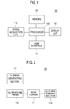
- FIG. 1 is a block diagram showing an illustrative embodiment of an ultrasound system.
- the ultrasound system 100 includes a signal acquisition unit 110, a memory 120, a user interface 130, a processor 140 and a display unit 150.
- the signal acquisition unit 110 transmits and receives ultrasound signals to and from a target object to thereby output baseband IQ signals to be used in forming frames.
- the frames include color Doppler mode image frames.
- FIG. 2 is a block diagram showing an illustrative embodiment of the signal acquisition unit 110.
- the signal acquisition unit 110 includes a transmit (Tx) signal generating section 111, an ultrasound probe 112 having a plurality of transducer elements (not shown), a beam former 113 and a IQ signal forming section 114.
- the Tx signal generating section 111 generates Tx signals.
- the Tx signal generating section 111 generates the Tx signals and apply delays to the Tx signals in consideration of distances between the respective transducer elements and focal points for acquiring ultrasound images indicative of the target object.
- the ultrasound images include the color Doppler mode image.
- the ultrasound probe 112 includes the plurality of transducer elements for reciprocally converting between electrical signals and ultrasound signals.
- the ultrasound probe 112 transmits ultrasound signals to the target object in response to the Tx signals provided from the Tx signal generating section 111.
- the ultrasound probe 112 receives ultrasound echo signals reflected from the target object to thereby output the received signals.
- the transmission and reception of the ultrasound signals are sequentially and iteratively carried out to form the received signals.
- the received signals are analog signals.
- the ultrasound probe 112 includes a three-dimensional mechanical probe, a 2D array probe and the like. However, it should be noted herein that the ultrasound probe 112 may not be limited thereto.
- the beam former 113 converts the received signals provided from the ultrasound probe 112 into digital signals.
- the beam former 113 applies delays to the digital signals in consideration of distances between the transducer elements and focal points to thereby output digital receive-focused signals.
- the IQ signal forming section 114 performs decimation on the digital receive-focused signals to thereby form the baseband IQ signal.
- the baseband IQ signal includes clutter signals due to reflection of the ultrasound signals from stationary or slowly moving tissues, Doppler signals due to the reflection of the ultrasound signals from blood flow, and noise signals.
- the decimation is a technique for reducing the number of samples of the baseband IQ signal.
- the memory 120 stores a plurality of filter coefficients of a plurality of filters for clutter filtering.
- the filter coefficients are determined and stored according to various storage conditions such as filter types, filter orders, ensemble numbers, cutoff frequencies, stopband attenuations, stopband widths, passband gains, passband ripples and the like.
- the ensemble numbers represent the number of transmission and reception of the ultrasound signals for acquiring the Doppler signals of a scanline.
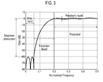
- FIG. 3 is a graph showing an example of a response curve of a high pass filter.
- the graph shows a stopband to be removed after the clutter filtering, a passband to be remained after the clutter filtering, a transition band between the stopband and the passband, a stopband attenuation indicative of a gain of the stopband and a passband ripple.
- the filter includes a finite impulse response (FIR) filter, an infinite impulse response (IIR) filter, and a regression filter and the like.
- FIR finite impulse response
- IIR infinite impulse response
- various initialization techniques are used to remove a transient state.
- the initialization techniques include zero, step, exponential, and projection initialization techniques and the like.
- the regression filter is classified into a polynomial regression filter, a sinusoidal regression filter and the like according to a basis function thereof.
- FIG. 4 is a schematic diagram showing an example of a filter table, which shows filters determined according to the ensemble number and the cutoff frequency at a stopband of 60dB.
- Filter_A is one of a 1st order projection-initialized IIR Butterworth filter to a 10th order projection-initialized IIR Butterworth filter
- Filter_B is one of a 1st order projection-initialized IIR Elliptic filter to a 10th order projection-initialized IIR Butterworth filter
- Filter_C is a modified polynomial regression filter
- the Filter_D is a modified sinusoidal regression filter.
- the filter types are not limited thereto. In one embodiment, it is possible to add a new filter to the filter table or delete a filter from the filter table.
- the memory 120 stores information on an error condition for determining filters that are matched corresponding to a filter selection condition.
- the error condition is indicative of a specific filter property and inputted through the user interface 130 when extracting filters from the filter table.
- the error condition includes a permissible matching range, e.g., +/- 10% with respect to the filter selection condition.
- the memory 120 stores information on filter decision condition for deciding one of the filters selected according to the filter selection condition and the error condition.
- the filter decision condition includes a condition for selecting a filter having the widest stopband, a condition for selecting a filter having the narrowest transitionband, a condition for selecting a filter having the best phase response and the like.
- the user interface 130 receives the filter selection condition for selecting at least two filters among a plurality of filters stored in the memory 120.
- the filter selection condition is a condition for selecting whole or partial filter coefficients stored in the memory 120.
- the filter selection condition is defined by specifying the ensemble number, the cutoff frequency, the stopband attenuation, the filter order, the passband ripple and the like.
- the ensemble number is in a range of 2-32
- the cutoff frequency is ranging from 0.05 Hz to 0.44 Hz
- the stopband attenuation is ranging from 40 dB to 100 dB
- the filter order is in a range of 1-10.
- the processor 140 extracts filters from the filter table stored in the memory 120 by using the filter selection condition and the error condition and decide a proper filter among the extracted filters by using the filter decision condition.
- the processor 140 filters the baseband IQ signals by using the filter coefficients of the decided filter to thereby extract the Doppler signals from the baseband IQ signals.
- the processor 140 forms the color Doppler mode image by using the extracted Doppler signals.
- the color Doppler mode image includes a power mode image that visualizes powers of Doppler signals as two-dimensional (2D) distribution and a velocity mode image that visualizes velocities of the moving objects, whose velocities are computed from the Doppler signals, as 2D distribution. Because the clutter signal included in the baseband IQ signal is mostly spread through low frequency band while the Doppler signal is spread through high frequency band, the processor 140 filters the baseband IQ signal by using a high pass filter to extract the Doppler signal.
- the display unit 150 displays the color Doppler mode image formed by the processor 140.
- the display unit 150 includes a cathode ray tube (CRT) display, a liquid crystal display (LCD), an organic light emitting diodes (OLED) display and the like.
- CTR cathode ray tube
- LCD liquid crystal display
- OLED organic light emitting diodes
- any reference in this specification to "one embodiment,” “an embodiment,” “example embodiment,” “illustrative embodiment,” etc. means that a particular feature, structure or characteristic described in connection with the embodiment is included in at least one embodiment of the present invention.
- the appearances of such phrases in various places in the specification are not necessarily all referring to the same embodiment.
Landscapes
- Engineering & Computer Science (AREA)
- Health & Medical Sciences (AREA)
- Life Sciences & Earth Sciences (AREA)
- Physics & Mathematics (AREA)
- Radar, Positioning & Navigation (AREA)
- Remote Sensing (AREA)
- General Health & Medical Sciences (AREA)
- Medical Informatics (AREA)
- Nuclear Medicine, Radiotherapy & Molecular Imaging (AREA)
- Radiology & Medical Imaging (AREA)
- General Physics & Mathematics (AREA)
- Biomedical Technology (AREA)
- Animal Behavior & Ethology (AREA)
- Veterinary Medicine (AREA)
- Biophysics (AREA)
- Pathology (AREA)
- Public Health (AREA)
- Heart & Thoracic Surgery (AREA)
- Molecular Biology (AREA)
- Surgery (AREA)
- Acoustics & Sound (AREA)
- Computer Networks & Wireless Communication (AREA)
- Computer Vision & Pattern Recognition (AREA)
- Theoretical Computer Science (AREA)
- Quality & Reliability (AREA)
- Vascular Medicine (AREA)
- Ultra Sonic Daignosis Equipment (AREA)
Abstract
Description
- The present application claims priority from Korean Patent Application No.
10-2009-0123845 filed on December 14. 2009 - The present invention generally relates to ultrasound systems, and more particularly to an ultrasound system and method for adaptive clutter filtering.
- An ultrasound system has become an important and popular diagnostic tool due to its non-invasive and non-destructive nature. The ultrasound system can provide high dimensional real-time ultrasound images of inner parts of target objects without a surgical operation. The ultrasound system operates in various image modes such as a brightness mode, a Doppler mode and the like to acquire the ultrasound images for diagnosis.
- In the Doppler mode, the ultrasound system can provide a color Doppler mode image that visualizes velocities of moving objects (e.g., blood flow, heart, etc.) or scattered objects. The color Doppler mode image includes a power mode image visualizing powers of Doppler signals as two-dimensional (2D) distribution and a velocity mode image visualizing velocities of the moving objects, which may be computed from the Doppler signals, as 2D distribution. The color Doppler mode image not only visualizes the blood flow in real time but also represents a status of the blood flow at a wide range from the blood flow of a high velocity in a large vessel to the blood flow of a low velocity in a small vessel.
- The Doppler signals includes low frequency signals (so-called clutter signals) due to motion of a cardiac wall or valve of a heart. The clutter signals can be an obstacle to accurately detecting velocities of the blood flow. Thus, the ultrasound system employs a clutter filter to remove the clutter signals.
- The clutter signals are typically distributed at the low frequency band and pure Doppler signals are typically distributed at a high frequency band. Thus, a high pass filter is used to extract the pure Doppler signals. Since the clutter signals have higher amplitude than the Doppler signals, it is required to use a high pass filter of good performance to extract the pure Doppler signals.
- An embodiment for adaptive clutter filtering is disclosed herein. In one embodiment, by way of non-limiting example, an ultrasound system may include: a signal acquisition unit configured to transmit and receive ultrasound signals to and from a target object to output baseband IQ signals; a memory configured to store an error condition, a filter decision condition and information on at least two of filters for filtering the baseband IQ signals; a user interface configured to receive a filter selection condition for selecting at least two filters among a plurality of filters stored in the memory; and a processor configured to extract at least two of filters from the memory according to the filter selection condition and the error condition, decide a filter among the extracted at least two of filters and filter the baseband IQ signals by using filter coefficients of the decided filter.
- In another embodiment, a method of implementing adaptive clutter filtering may comprise: transmitting and receiving ultrasound signals to and from a target object to output baseband IQ signals; receiving a filter selection condition for selecting at least two of filters among a plurality of filters stored in a memory, wherein the memory comprises the filter selection condition, an error condition and a filter decision condition; extracting at least two of filters from the memory according to the filter selection condition and the error condition; deciding a filter among the extracted at least two of filters based on the filter decision condition; and filtering the baseband IQ signals by using filter coefficients of the decided filter.
- This Summary is provided to introduce a selection of concepts in a simplified form that are further described below in the Detailed Description. This Summary is not intended to identify key or essential features of the claimed subject matter, nor is it intended to be used in determining the scope of the claimed subject matter.
-
- FIG. 1
- is a block diagram showing an illustrative embodiment of an ultrasound system.
- FIG. 2
- is a block diagram showing an illustrative embodiment of a signal acquisition unit in
FIG. 1 . - FIG. 3
- is a graph showing an example of a response curve of a high pass filter.
- FIG. 4
- is a schematic diagram showing an example of a filter table.
- This detailed description is provided with reference to the accompanying drawings. One of ordinary skill in the art may realize that the following description is illustrative only and is not in any way limiting. Other embodiments of the present invention may readily suggest themselves to such skilled persons having the benefit of this disclosure.
-
FIG. 1 is a block diagram showing an illustrative embodiment of an ultrasound system. As depicted therein, theultrasound system 100 includes asignal acquisition unit 110, amemory 120, auser interface 130, aprocessor 140 and adisplay unit 150. - The
signal acquisition unit 110 transmits and receives ultrasound signals to and from a target object to thereby output baseband IQ signals to be used in forming frames. The frames include color Doppler mode image frames. -
FIG. 2 is a block diagram showing an illustrative embodiment of thesignal acquisition unit 110. Thesignal acquisition unit 110 includes a transmit (Tx)signal generating section 111, anultrasound probe 112 having a plurality of transducer elements (not shown), a beam former 113 and a IQsignal forming section 114. - The Tx
signal generating section 111 generates Tx signals. The Txsignal generating section 111 generates the Tx signals and apply delays to the Tx signals in consideration of distances between the respective transducer elements and focal points for acquiring ultrasound images indicative of the target object. The ultrasound images include the color Doppler mode image. - The
ultrasound probe 112 includes the plurality of transducer elements for reciprocally converting between electrical signals and ultrasound signals. Theultrasound probe 112 transmits ultrasound signals to the target object in response to the Tx signals provided from the Txsignal generating section 111. Theultrasound probe 112 receives ultrasound echo signals reflected from the target object to thereby output the received signals. The transmission and reception of the ultrasound signals are sequentially and iteratively carried out to form the received signals. The received signals are analog signals. Theultrasound probe 112 includes a three-dimensional mechanical probe, a 2D array probe and the like. However, it should be noted herein that theultrasound probe 112 may not be limited thereto. - The beam former 113 converts the received signals provided from the
ultrasound probe 112 into digital signals. The beam former 113 applies delays to the digital signals in consideration of distances between the transducer elements and focal points to thereby output digital receive-focused signals. - The IQ
signal forming section 114 performs decimation on the digital receive-focused signals to thereby form the baseband IQ signal. The baseband IQ signal includes clutter signals due to reflection of the ultrasound signals from stationary or slowly moving tissues, Doppler signals due to the reflection of the ultrasound signals from blood flow, and noise signals. The decimation is a technique for reducing the number of samples of the baseband IQ signal. - Referring back to
FIG. 1 , thememory 120 stores a plurality of filter coefficients of a plurality of filters for clutter filtering. The filter coefficients are determined and stored according to various storage conditions such as filter types, filter orders, ensemble numbers, cutoff frequencies, stopband attenuations, stopband widths, passband gains, passband ripples and the like. The ensemble numbers represent the number of transmission and reception of the ultrasound signals for acquiring the Doppler signals of a scanline. -
FIG. 3 is a graph showing an example of a response curve of a high pass filter. The graph shows a stopband to be removed after the clutter filtering, a passband to be remained after the clutter filtering, a transition band between the stopband and the passband, a stopband attenuation indicative of a gain of the stopband and a passband ripple. The filter includes a finite impulse response (FIR) filter, an infinite impulse response (IIR) filter, and a regression filter and the like. In the case of using the IIR filter, various initialization techniques are used to remove a transient state. The initialization techniques include zero, step, exponential, and projection initialization techniques and the like. The regression filter is classified into a polynomial regression filter, a sinusoidal regression filter and the like according to a basis function thereof. -
FIG. 4 is a schematic diagram showing an example of a filter table, which shows filters determined according to the ensemble number and the cutoff frequency at a stopband of 60dB. In the filter table shown inFIG. 4 , Filter_A is one of a 1st order projection-initialized IIR Butterworth filter to a 10th order projection-initialized IIR Butterworth filter, Filter_B is one of a 1st order projection-initialized IIR Elliptic filter to a 10th order projection-initialized IIR Butterworth filter, Filter_C is a modified polynomial regression filter, and the Filter_D is a modified sinusoidal regression filter. But, the filter types are not limited thereto. In one embodiment, it is possible to add a new filter to the filter table or delete a filter from the filter table. - The
memory 120 stores information on an error condition for determining filters that are matched corresponding to a filter selection condition. The error condition is indicative of a specific filter property and inputted through theuser interface 130 when extracting filters from the filter table. In one embodiment, the error condition includes a permissible matching range, e.g., +/- 10% with respect to the filter selection condition. - Furthermore, the
memory 120 stores information on filter decision condition for deciding one of the filters selected according to the filter selection condition and the error condition. In one embodiment, the filter decision condition includes a condition for selecting a filter having the widest stopband, a condition for selecting a filter having the narrowest transitionband, a condition for selecting a filter having the best phase response and the like. - The
user interface 130 receives the filter selection condition for selecting at least two filters among a plurality of filters stored in thememory 120. The filter selection condition is a condition for selecting whole or partial filter coefficients stored in thememory 120. The filter selection condition is defined by specifying the ensemble number, the cutoff frequency, the stopband attenuation, the filter order, the passband ripple and the like. In one embodiment, the ensemble number is in a range of 2-32, the cutoff frequency is ranging from 0.05 Hz to 0.44 Hz, the stopband attenuation is ranging from 40 dB to 100 dB, and the filter order is in a range of 1-10. - The
processor 140 extracts filters from the filter table stored in thememory 120 by using the filter selection condition and the error condition and decide a proper filter among the extracted filters by using the filter decision condition. Theprocessor 140 filters the baseband IQ signals by using the filter coefficients of the decided filter to thereby extract the Doppler signals from the baseband IQ signals. Theprocessor 140 forms the color Doppler mode image by using the extracted Doppler signals. The color Doppler mode image includes a power mode image that visualizes powers of Doppler signals as two-dimensional (2D) distribution and a velocity mode image that visualizes velocities of the moving objects, whose velocities are computed from the Doppler signals, as 2D distribution. Because the clutter signal included in the baseband IQ signal is mostly spread through low frequency band while the Doppler signal is spread through high frequency band, theprocessor 140 filters the baseband IQ signal by using a high pass filter to extract the Doppler signal. - The
display unit 150 displays the color Doppler mode image formed by theprocessor 140. Thedisplay unit 150 includes a cathode ray tube (CRT) display, a liquid crystal display (LCD), an organic light emitting diodes (OLED) display and the like. - Any reference in this specification to "one embodiment," "an embodiment," "example embodiment," "illustrative embodiment," etc. means that a particular feature, structure or characteristic described in connection with the embodiment is included in at least one embodiment of the present invention. The appearances of such phrases in various places in the specification are not necessarily all referring to the same embodiment. Further, when a particular feature, structure or characteristic is described in connection with any embodiment, it is submitted that it is within the purview of one skilled in the art to affect such feature, structure or characteristic in connection with other embodiments.
- Although embodiments have been described with reference to a number of illustrative embodiments thereof, it should be understood that numerous other modifications and embodiments can be devised by those skilled in the art that will fall within the scope of the principles of this disclosure. More particularly, numerous variations and modifications are possible in the component parts and/or arrangements of the subject combination arrangement within the scope of the disclosure, the drawings and the appended claims. In addition to variations and modifications in the component parts and/or arrangements, alternative uses will also be apparent to those skilled in the art.
Claims (10)
- An ultrasound system, comprising:a signal acquisition unit configured to transmit and receive ultrasound signals to and from a target object to output baseband IQ signals;a memory configured to store an error condition, a filter decision condition and information on at least two of filters for filtering the baseband IQ signals;a user interface configured to receive a filter selection condition for selecting at least two filters among a plurality of filters stored in the memory; anda processor configured to extract at least two of filters from the memory according to the filter selection condition and the error condition, decide a filter among the extracted at least two of filters and filter the baseband IQ signals by using filter coefficients of the decided filter.
- The ultrasound system of Claim 1, wherein the signal acquisition unit comprises :a Tx signal generating section configured to generate Tx signals;a ultrasound probe configured to transmit ultrasound signals to the target object in response to the Tx signals and receive ultrasound echo signals reflected from the target object to output the received signals;a beam former configured to convert the received signals into digital signals and apply delays to the digital signals in consideration of distances between transducer elements and focal points to output digital receive-focused signals; anda IQ signal forming section configured to perform decimation on the digital receive-focused signals to form the baseband IQ signal.
- The ultrasound system of Claim 1, wherein the filter selection condition are defined by at least one of the ensemble number, the cutoff frequency, the stopband attenuation, the filter order and the passband ripple.
- The ultrasound system of Claim 1, wherein the error condition includes a permissible matching range with respect to the filter selection condition.
- The ultrasound system of Claim 1, wherein the filter decision condition includes one of a condition for selecting a filter having the widest stopband, a condition for selecting a filter having the narrowest transitionband and a condition for selecting a filter having the best phase response.
- An adaptive clutter filtering method comprising:transmitting and receiving ultrasound signals to and from a target object to output baseband IQ signals;receiving a filter selection condition for selecting at least two of filters among a plurality of filters stored in a memory, wherein the memory comprises the filter selection condition, an error condition and a filter decision condition;extracting at least two of filters from the memory according to the filter selection condition and the error condition;deciding a filter among the extracted at least two of filters based on the filter decision condition; andfiltering the baseband IQ signals by using filter coefficients of the decided filter.
- The method of Claim 6, wherein the transmitting and receiving ultrasound signals comprises:generating Tx signals;transmitting ultrasound signals to the target object in response to the Tx signals and receiving ultrasound echo signals reflected from the target object to output the received signals;converting the received signals into digital signals and applying delays to the digital signals in consideration of distances between transducer elements and focal points to output digital receive-focused signals; andperforming decimation on the digital receive-focused signals to form the baseband IQ signal.
- The method of Claim 6, wherein the filter selection condition are defined by at least one of the ensemble number, the cutoff frequency, the stopband attenuation, the filter order and the passband ripple.
- The method of Claim 6, wherein the error condition includes a permissible matching range with respect to the filter selection condition.
- The method of Claim 6, wherein the filter decision condition includes one of a condition for selecting a filter having the widest stopband, a condition for selecting a filter having the narrowest transitionband and a condition for selecting a filter having the best phase response.
Applications Claiming Priority (1)
| Application Number | Priority Date | Filing Date | Title |
|---|---|---|---|
| KR1020090123845A KR101175421B1 (en) | 2009-12-14 | 2009-12-14 | Adaptive clutter filtering method and ultrasound system for the same |
Publications (3)
| Publication Number | Publication Date |
|---|---|
| EP2341364A2 true EP2341364A2 (en) | 2011-07-06 |
| EP2341364A3 EP2341364A3 (en) | 2013-08-07 |
| EP2341364B1 EP2341364B1 (en) | 2017-11-01 |
Family
ID=43734021
Family Applications (1)
| Application Number | Title | Priority Date | Filing Date |
|---|---|---|---|
| EP10192788.7A Not-in-force EP2341364B1 (en) | 2009-12-14 | 2010-11-26 | Adaptive clutter filtering method and ultrasound system for the same |
Country Status (4)
| Country | Link |
|---|---|
| US (1) | US8870774B2 (en) |
| EP (1) | EP2341364B1 (en) |
| JP (1) | JP5671319B2 (en) |
| KR (1) | KR101175421B1 (en) |
Families Citing this family (4)
| Publication number | Priority date | Publication date | Assignee | Title |
|---|---|---|---|---|
| US9641866B2 (en) * | 2011-08-18 | 2017-05-02 | Qualcomm Incorporated | Applying partition-based filters |
| EP3352166B1 (en) * | 2017-01-19 | 2023-08-30 | Esaote S.p.A. | Systems and methods for distortion free multi beam ultrasound receive beamforming |
| US11300653B2 (en) * | 2019-07-11 | 2022-04-12 | University Corporation For Atmospheric Research | Frequency compensation for clutter filter bias to radar data |
| JP7848607B2 (en) * | 2022-06-17 | 2026-04-21 | コニカミノルタ株式会社 | Ultrasound diagnostic device, method for controlling the ultrasound diagnostic device, and control program for the ultrasound diagnostic device |
Family Cites Families (11)
| Publication number | Priority date | Publication date | Assignee | Title |
|---|---|---|---|---|
| US5524629A (en) * | 1994-11-02 | 1996-06-11 | General Electric Company | Color flow processor having adaptive wall filter |
| US5735797A (en) * | 1996-12-30 | 1998-04-07 | General Electric Company | Method and apparatus for combining topographic flow power imagery with a B-mode anatomical imagery |
| US6074348A (en) * | 1998-03-31 | 2000-06-13 | General Electric Company | Method and apparatus for enhanced flow imaging in B-mode ultrasound |
| US6210332B1 (en) * | 1998-03-31 | 2001-04-03 | General Electric Company | Method and apparatus for flow imaging using coded excitation |
| US6511426B1 (en) * | 1998-06-02 | 2003-01-28 | Acuson Corporation | Medical diagnostic ultrasound system and method for versatile processing |
| JPH11347035A (en) * | 1998-06-11 | 1999-12-21 | Hitachi Medical Corp | Ultrasonic diagnostic device |
| KR100352638B1 (en) | 1999-05-06 | 2002-09-18 | 주식회사 메디슨 | Clutter signal filtering method and apparatus for ultrasound color doppler system |
| US6689064B2 (en) * | 2001-06-22 | 2004-02-10 | Koninklijke Philips Electronics N.V. | Ultrasound clutter filter |
| US6663567B2 (en) * | 2002-03-19 | 2003-12-16 | Zonare Medical Systems, Inc. | System and method for post-processing ultrasound color doppler imaging |
| JP4359093B2 (en) * | 2003-07-08 | 2009-11-04 | パナソニック株式会社 | Ultrasonic diagnostic equipment |
| EP1671155A1 (en) | 2003-09-30 | 2006-06-21 | Koninklijke Philips Electronics N.V. | Clutter filtering with small ensemble lengths in ultrasound imaging |
-
2009
- 2009-12-14 KR KR1020090123845A patent/KR101175421B1/en active Active
-
2010
- 2010-11-26 EP EP10192788.7A patent/EP2341364B1/en not_active Not-in-force
- 2010-12-08 JP JP2010273767A patent/JP5671319B2/en not_active Expired - Fee Related
- 2010-12-10 US US12/965,499 patent/US8870774B2/en active Active
Non-Patent Citations (1)
| Title |
|---|
| None |
Also Published As
| Publication number | Publication date |
|---|---|
| EP2341364A3 (en) | 2013-08-07 |
| JP5671319B2 (en) | 2015-02-18 |
| KR101175421B1 (en) | 2012-08-20 |
| EP2341364B1 (en) | 2017-11-01 |
| KR20110067305A (en) | 2011-06-22 |
| US20110144489A1 (en) | 2011-06-16 |
| US8870774B2 (en) | 2014-10-28 |
| JP2011120909A (en) | 2011-06-23 |
Similar Documents
| Publication | Publication Date | Title |
|---|---|---|
| EP1188068B1 (en) | Method and apparatus for flash suppression in two-dimensional ultrasound imaging | |
| US8684934B2 (en) | Adaptively performing clutter filtering in an ultrasound system | |
| US6733455B2 (en) | System and method for adaptive clutter filtering in ultrasound color flow imaging | |
| EP2397867B1 (en) | Adaptive clutter filtering in an ultrasound system | |
| KR102041433B1 (en) | Sparkle artifact detection in ultrasound color flow | |
| CN105997148B (en) | Pulse Doppler ultrahigh spectral resolution imaging processing method and processing system | |
| EP2609871A1 (en) | Providing vector doppler image based on decision data in ultrasound system | |
| US9261485B2 (en) | Providing color doppler image based on qualification curve information in ultrasound system | |
| JP6188594B2 (en) | Ultrasonic diagnostic apparatus, image processing apparatus, and image processing method | |
| JP6305470B2 (en) | Improved Doppler imaging | |
| EP2609868A1 (en) | Providing user interface in ultrasound system | |
| US11154278B2 (en) | Ultrasound signal processing device, ultrasound diagnostic device, and ultrasound signal processing method for calculating blood flow and tissue information | |
| EP2610641B1 (en) | Ultrasound and system for forming a Doppler ultrasound image | |
| US8894581B2 (en) | Performing adaptive frame average process in ultrasound system | |
| US8705802B2 (en) | Providing a motion image in an ultrasound system | |
| EP2609866A1 (en) | Providing motion mode image in ultrasound system | |
| US8870774B2 (en) | Adaptive clutter filtering method and ultrasound system for the same | |
| JP4712931B2 (en) | Method and apparatus for optimal data mapping of power Doppler images | |
| EP2609869A1 (en) | Providing particle flow image in ultrasound system | |
| JP2007507271A (en) | Clutter filtering by small ensemble length in ultrasound imaging | |
| KR101221309B1 (en) | Ultrasound system and method for providing doppler mode image based on extrapolation | |
| EP2380498A1 (en) | Adaptive clutter filtering in an ultrasound system |
Legal Events
| Date | Code | Title | Description |
|---|---|---|---|
| PUAI | Public reference made under article 153(3) epc to a published international application that has entered the european phase |
Free format text: ORIGINAL CODE: 0009012 |
|
| AK | Designated contracting states |
Kind code of ref document: A2 Designated state(s): AL AT BE BG CH CY CZ DE DK EE ES FI FR GB GR HR HU IE IS IT LI LT LU LV MC MK MT NL NO PL PT RO RS SE SI SK SM TR |
|
| AX | Request for extension of the european patent |
Extension state: BA ME |
|
| PUAL | Search report despatched |
Free format text: ORIGINAL CODE: 0009013 |
|
| AK | Designated contracting states |
Kind code of ref document: A3 Designated state(s): AL AT BE BG CH CY CZ DE DK EE ES FI FR GB GR HR HU IE IS IT LI LT LU LV MC MK MT NL NO PL PT RO RS SE SI SK SM TR |
|
| AX | Request for extension of the european patent |
Extension state: BA ME |
|
| RIC1 | Information provided on ipc code assigned before grant |
Ipc: G01S 15/89 20060101ALI20130701BHEP Ipc: G01S 7/52 20060101AFI20130701BHEP |
|
| 17P | Request for examination filed |
Effective date: 20140206 |
|
| RBV | Designated contracting states (corrected) |
Designated state(s): AL AT BE BG CH CY CZ DE DK EE ES FI FR GB GR HR HU IE IS IT LI LT LU LV MC MK MT NL NO PL PT RO RS SE SI SK SM TR |
|
| 17Q | First examination report despatched |
Effective date: 20160928 |
|
| GRAP | Despatch of communication of intention to grant a patent |
Free format text: ORIGINAL CODE: EPIDOSNIGR1 |
|
| INTG | Intention to grant announced |
Effective date: 20170620 |
|
| RIN1 | Information on inventor provided before grant (corrected) |
Inventor name: KWAK, HAN Inventor name: LEE, JAE KEUN |
|
| GRAS | Grant fee paid |
Free format text: ORIGINAL CODE: EPIDOSNIGR3 |
|
| GRAA | (expected) grant |
Free format text: ORIGINAL CODE: 0009210 |
|
| AK | Designated contracting states |
Kind code of ref document: B1 Designated state(s): AL AT BE BG CH CY CZ DE DK EE ES FI FR GB GR HR HU IE IS IT LI LT LU LV MC MK MT NL NO PL PT RO RS SE SI SK SM TR |
|
| RAP1 | Party data changed (applicant data changed or rights of an application transferred) |
Owner name: SAMSUNG MEDISON CO., LTD. |
|
| REG | Reference to a national code |
Ref country code: GB Ref legal event code: FG4D |
|
| REG | Reference to a national code |
Ref country code: FR Ref legal event code: PLFP Year of fee payment: 8 |
|
| REG | Reference to a national code |
Ref country code: CH Ref legal event code: EP Ref country code: AT Ref legal event code: REF Ref document number: 942577 Country of ref document: AT Kind code of ref document: T Effective date: 20171115 |
|
| REG | Reference to a national code |
Ref country code: IE Ref legal event code: FG4D |
|
| REG | Reference to a national code |
Ref country code: DE Ref legal event code: R096 Ref document number: 602010046334 Country of ref document: DE |
|
| REG | Reference to a national code |
Ref country code: NL Ref legal event code: FP |
|
| REG | Reference to a national code |
Ref country code: LT Ref legal event code: MG4D |
|
| REG | Reference to a national code |
Ref country code: AT Ref legal event code: MK05 Ref document number: 942577 Country of ref document: AT Kind code of ref document: T Effective date: 20171101 |
|
| PG25 | Lapsed in a contracting state [announced via postgrant information from national office to epo] |
Ref country code: FI Free format text: LAPSE BECAUSE OF FAILURE TO SUBMIT A TRANSLATION OF THE DESCRIPTION OR TO PAY THE FEE WITHIN THE PRESCRIBED TIME-LIMIT Effective date: 20171101 Ref country code: NO Free format text: LAPSE BECAUSE OF FAILURE TO SUBMIT A TRANSLATION OF THE DESCRIPTION OR TO PAY THE FEE WITHIN THE PRESCRIBED TIME-LIMIT Effective date: 20180201 Ref country code: SE Free format text: LAPSE BECAUSE OF FAILURE TO SUBMIT A TRANSLATION OF THE DESCRIPTION OR TO PAY THE FEE WITHIN THE PRESCRIBED TIME-LIMIT Effective date: 20171101 Ref country code: ES Free format text: LAPSE BECAUSE OF FAILURE TO SUBMIT A TRANSLATION OF THE DESCRIPTION OR TO PAY THE FEE WITHIN THE PRESCRIBED TIME-LIMIT Effective date: 20171101 Ref country code: LT Free format text: LAPSE BECAUSE OF FAILURE TO SUBMIT A TRANSLATION OF THE DESCRIPTION OR TO PAY THE FEE WITHIN THE PRESCRIBED TIME-LIMIT Effective date: 20171101 |
|
| PG25 | Lapsed in a contracting state [announced via postgrant information from national office to epo] |
Ref country code: RS Free format text: LAPSE BECAUSE OF FAILURE TO SUBMIT A TRANSLATION OF THE DESCRIPTION OR TO PAY THE FEE WITHIN THE PRESCRIBED TIME-LIMIT Effective date: 20171101 Ref country code: BG Free format text: LAPSE BECAUSE OF FAILURE TO SUBMIT A TRANSLATION OF THE DESCRIPTION OR TO PAY THE FEE WITHIN THE PRESCRIBED TIME-LIMIT Effective date: 20180201 Ref country code: GR Free format text: LAPSE BECAUSE OF FAILURE TO SUBMIT A TRANSLATION OF THE DESCRIPTION OR TO PAY THE FEE WITHIN THE PRESCRIBED TIME-LIMIT Effective date: 20180202 Ref country code: HR Free format text: LAPSE BECAUSE OF FAILURE TO SUBMIT A TRANSLATION OF THE DESCRIPTION OR TO PAY THE FEE WITHIN THE PRESCRIBED TIME-LIMIT Effective date: 20171101 Ref country code: AT Free format text: LAPSE BECAUSE OF FAILURE TO SUBMIT A TRANSLATION OF THE DESCRIPTION OR TO PAY THE FEE WITHIN THE PRESCRIBED TIME-LIMIT Effective date: 20171101 Ref country code: IS Free format text: LAPSE BECAUSE OF FAILURE TO SUBMIT A TRANSLATION OF THE DESCRIPTION OR TO PAY THE FEE WITHIN THE PRESCRIBED TIME-LIMIT Effective date: 20180301 Ref country code: LV Free format text: LAPSE BECAUSE OF FAILURE TO SUBMIT A TRANSLATION OF THE DESCRIPTION OR TO PAY THE FEE WITHIN THE PRESCRIBED TIME-LIMIT Effective date: 20171101 |
|
| PG25 | Lapsed in a contracting state [announced via postgrant information from national office to epo] |
Ref country code: CZ Free format text: LAPSE BECAUSE OF FAILURE TO SUBMIT A TRANSLATION OF THE DESCRIPTION OR TO PAY THE FEE WITHIN THE PRESCRIBED TIME-LIMIT Effective date: 20171101 Ref country code: LI Free format text: LAPSE BECAUSE OF NON-PAYMENT OF DUE FEES Effective date: 20171130 Ref country code: CH Free format text: LAPSE BECAUSE OF NON-PAYMENT OF DUE FEES Effective date: 20171130 Ref country code: SK Free format text: LAPSE BECAUSE OF FAILURE TO SUBMIT A TRANSLATION OF THE DESCRIPTION OR TO PAY THE FEE WITHIN THE PRESCRIBED TIME-LIMIT Effective date: 20171101 Ref country code: DK Free format text: LAPSE BECAUSE OF FAILURE TO SUBMIT A TRANSLATION OF THE DESCRIPTION OR TO PAY THE FEE WITHIN THE PRESCRIBED TIME-LIMIT Effective date: 20171101 Ref country code: EE Free format text: LAPSE BECAUSE OF FAILURE TO SUBMIT A TRANSLATION OF THE DESCRIPTION OR TO PAY THE FEE WITHIN THE PRESCRIBED TIME-LIMIT Effective date: 20171101 Ref country code: CY Free format text: LAPSE BECAUSE OF FAILURE TO SUBMIT A TRANSLATION OF THE DESCRIPTION OR TO PAY THE FEE WITHIN THE PRESCRIBED TIME-LIMIT Effective date: 20171101 |
|
| REG | Reference to a national code |
Ref country code: DE Ref legal event code: R097 Ref document number: 602010046334 Country of ref document: DE |
|
| PG25 | Lapsed in a contracting state [announced via postgrant information from national office to epo] |
Ref country code: LU Free format text: LAPSE BECAUSE OF NON-PAYMENT OF DUE FEES Effective date: 20171126 Ref country code: SM Free format text: LAPSE BECAUSE OF FAILURE TO SUBMIT A TRANSLATION OF THE DESCRIPTION OR TO PAY THE FEE WITHIN THE PRESCRIBED TIME-LIMIT Effective date: 20171101 Ref country code: PL Free format text: LAPSE BECAUSE OF FAILURE TO SUBMIT A TRANSLATION OF THE DESCRIPTION OR TO PAY THE FEE WITHIN THE PRESCRIBED TIME-LIMIT Effective date: 20171101 Ref country code: RO Free format text: LAPSE BECAUSE OF FAILURE TO SUBMIT A TRANSLATION OF THE DESCRIPTION OR TO PAY THE FEE WITHIN THE PRESCRIBED TIME-LIMIT Effective date: 20171101 |
|
| REG | Reference to a national code |
Ref country code: BE Ref legal event code: MM Effective date: 20171130 |
|
| REG | Reference to a national code |
Ref country code: IE Ref legal event code: MM4A |
|
| PLBE | No opposition filed within time limit |
Free format text: ORIGINAL CODE: 0009261 |
|
| STAA | Information on the status of an ep patent application or granted ep patent |
Free format text: STATUS: NO OPPOSITION FILED WITHIN TIME LIMIT |
|
| PG25 | Lapsed in a contracting state [announced via postgrant information from national office to epo] |
Ref country code: MT Free format text: LAPSE BECAUSE OF NON-PAYMENT OF DUE FEES Effective date: 20171126 |
|
| REG | Reference to a national code |
Ref country code: FR Ref legal event code: PLFP Year of fee payment: 9 |
|
| 26N | No opposition filed |
Effective date: 20180802 |
|
| GBPC | Gb: european patent ceased through non-payment of renewal fee |
Effective date: 20180201 |
|
| PG25 | Lapsed in a contracting state [announced via postgrant information from national office to epo] |
Ref country code: IE Free format text: LAPSE BECAUSE OF NON-PAYMENT OF DUE FEES Effective date: 20171126 |
|
| PG25 | Lapsed in a contracting state [announced via postgrant information from national office to epo] |
Ref country code: SI Free format text: LAPSE BECAUSE OF FAILURE TO SUBMIT A TRANSLATION OF THE DESCRIPTION OR TO PAY THE FEE WITHIN THE PRESCRIBED TIME-LIMIT Effective date: 20171101 Ref country code: BE Free format text: LAPSE BECAUSE OF NON-PAYMENT OF DUE FEES Effective date: 20171130 |
|
| PG25 | Lapsed in a contracting state [announced via postgrant information from national office to epo] |
Ref country code: GB Free format text: LAPSE BECAUSE OF NON-PAYMENT OF DUE FEES Effective date: 20180201 |
|
| PG25 | Lapsed in a contracting state [announced via postgrant information from national office to epo] |
Ref country code: HU Free format text: LAPSE BECAUSE OF FAILURE TO SUBMIT A TRANSLATION OF THE DESCRIPTION OR TO PAY THE FEE WITHIN THE PRESCRIBED TIME-LIMIT; INVALID AB INITIO Effective date: 20101126 Ref country code: MC Free format text: LAPSE BECAUSE OF FAILURE TO SUBMIT A TRANSLATION OF THE DESCRIPTION OR TO PAY THE FEE WITHIN THE PRESCRIBED TIME-LIMIT Effective date: 20171101 |
|
| PG25 | Lapsed in a contracting state [announced via postgrant information from national office to epo] |
Ref country code: MK Free format text: LAPSE BECAUSE OF FAILURE TO SUBMIT A TRANSLATION OF THE DESCRIPTION OR TO PAY THE FEE WITHIN THE PRESCRIBED TIME-LIMIT Effective date: 20171101 |
|
| PGFP | Annual fee paid to national office [announced via postgrant information from national office to epo] |
Ref country code: NL Payment date: 20191007 Year of fee payment: 10 |
|
| PG25 | Lapsed in a contracting state [announced via postgrant information from national office to epo] |
Ref country code: TR Free format text: LAPSE BECAUSE OF FAILURE TO SUBMIT A TRANSLATION OF THE DESCRIPTION OR TO PAY THE FEE WITHIN THE PRESCRIBED TIME-LIMIT Effective date: 20171101 |
|
| PG25 | Lapsed in a contracting state [announced via postgrant information from national office to epo] |
Ref country code: PT Free format text: LAPSE BECAUSE OF FAILURE TO SUBMIT A TRANSLATION OF THE DESCRIPTION OR TO PAY THE FEE WITHIN THE PRESCRIBED TIME-LIMIT Effective date: 20171101 |
|
| PG25 | Lapsed in a contracting state [announced via postgrant information from national office to epo] |
Ref country code: AL Free format text: LAPSE BECAUSE OF FAILURE TO SUBMIT A TRANSLATION OF THE DESCRIPTION OR TO PAY THE FEE WITHIN THE PRESCRIBED TIME-LIMIT Effective date: 20171101 |
|
| REG | Reference to a national code |
Ref country code: NL Ref legal event code: MM Effective date: 20201201 |
|
| PG25 | Lapsed in a contracting state [announced via postgrant information from national office to epo] |
Ref country code: NL Free format text: LAPSE BECAUSE OF NON-PAYMENT OF DUE FEES Effective date: 20201201 |
|
| PGFP | Annual fee paid to national office [announced via postgrant information from national office to epo] |
Ref country code: IT Payment date: 20231009 Year of fee payment: 14 Ref country code: FR Payment date: 20231006 Year of fee payment: 14 Ref country code: DE Payment date: 20231005 Year of fee payment: 14 |
|
| REG | Reference to a national code |
Ref country code: DE Ref legal event code: R119 Ref document number: 602010046334 Country of ref document: DE |
|
| PG25 | Lapsed in a contracting state [announced via postgrant information from national office to epo] |
Ref country code: DE Free format text: LAPSE BECAUSE OF NON-PAYMENT OF DUE FEES Effective date: 20250603 |
|
| PG25 | Lapsed in a contracting state [announced via postgrant information from national office to epo] |
Ref country code: IT Free format text: LAPSE BECAUSE OF NON-PAYMENT OF DUE FEES Effective date: 20241126 |
|
| PG25 | Lapsed in a contracting state [announced via postgrant information from national office to epo] |
Ref country code: FR Free format text: LAPSE BECAUSE OF NON-PAYMENT OF DUE FEES Effective date: 20241130 |