EP2341231A2 - Frequency-tunable bracketless fluid manifold - Google Patents
Frequency-tunable bracketless fluid manifold Download PDFInfo
- Publication number
- EP2341231A2 EP2341231A2 EP10195954A EP10195954A EP2341231A2 EP 2341231 A2 EP2341231 A2 EP 2341231A2 EP 10195954 A EP10195954 A EP 10195954A EP 10195954 A EP10195954 A EP 10195954A EP 2341231 A2 EP2341231 A2 EP 2341231A2
- Authority
- EP
- European Patent Office
- Prior art keywords
- manifold
- fitting
- neck
- inner member
- coupling
- Prior art date
- Legal status (The legal status is an assumption and is not a legal conclusion. Google has not performed a legal analysis and makes no representation as to the accuracy of the status listed.)
- Withdrawn
Links
Images


Classifications
-
- F—MECHANICAL ENGINEERING; LIGHTING; HEATING; WEAPONS; BLASTING
- F01—MACHINES OR ENGINES IN GENERAL; ENGINE PLANTS IN GENERAL; STEAM ENGINES
- F01N—GAS-FLOW SILENCERS OR EXHAUST APPARATUS FOR MACHINES OR ENGINES IN GENERAL; GAS-FLOW SILENCERS OR EXHAUST APPARATUS FOR INTERNAL-COMBUSTION ENGINES
- F01N13/00—Exhaust or silencing apparatus characterised by constructional features
- F01N13/18—Construction facilitating manufacture, assembly, or disassembly
-
- F—MECHANICAL ENGINEERING; LIGHTING; HEATING; WEAPONS; BLASTING
- F02—COMBUSTION ENGINES; HOT-GAS OR COMBUSTION-PRODUCT ENGINE PLANTS
- F02C—GAS-TURBINE PLANTS; AIR INTAKES FOR JET-PROPULSION PLANTS; CONTROLLING FUEL SUPPLY IN AIR-BREATHING JET-PROPULSION PLANTS
- F02C7/00—Features, components parts, details or accessories, not provided for in, or of interest apart form groups F02C1/00 - F02C6/00; Air intakes for jet-propulsion plants
- F02C7/22—Fuel supply systems
- F02C7/222—Fuel flow conduits, e.g. manifolds
-
- F—MECHANICAL ENGINEERING; LIGHTING; HEATING; WEAPONS; BLASTING
- F05—INDEXING SCHEMES RELATING TO ENGINES OR PUMPS IN VARIOUS SUBCLASSES OF CLASSES F01-F04
- F05D—INDEXING SCHEME FOR ASPECTS RELATING TO NON-POSITIVE-DISPLACEMENT MACHINES OR ENGINES, GAS-TURBINES OR JET-PROPULSION PLANTS
- F05D2220/00—Application
- F05D2220/30—Application in turbines
- F05D2220/32—Application in turbines in gas turbines
-
- F—MECHANICAL ENGINEERING; LIGHTING; HEATING; WEAPONS; BLASTING
- F05—INDEXING SCHEMES RELATING TO ENGINES OR PUMPS IN VARIOUS SUBCLASSES OF CLASSES F01-F04
- F05D—INDEXING SCHEME FOR ASPECTS RELATING TO NON-POSITIVE-DISPLACEMENT MACHINES OR ENGINES, GAS-TURBINES OR JET-PROPULSION PLANTS
- F05D2230/00—Manufacture
- F05D2230/50—Building or constructing in particular ways
- F05D2230/51—Building or constructing in particular ways in a modular way, e.g. using several identical or complementary parts or features
-
- F—MECHANICAL ENGINEERING; LIGHTING; HEATING; WEAPONS; BLASTING
- F05—INDEXING SCHEMES RELATING TO ENGINES OR PUMPS IN VARIOUS SUBCLASSES OF CLASSES F01-F04
- F05D—INDEXING SCHEME FOR ASPECTS RELATING TO NON-POSITIVE-DISPLACEMENT MACHINES OR ENGINES, GAS-TURBINES OR JET-PROPULSION PLANTS
- F05D2250/00—Geometry
- F05D2250/70—Shape
- F05D2250/71—Shape curved
-
- F—MECHANICAL ENGINEERING; LIGHTING; HEATING; WEAPONS; BLASTING
- F05—INDEXING SCHEMES RELATING TO ENGINES OR PUMPS IN VARIOUS SUBCLASSES OF CLASSES F01-F04
- F05D—INDEXING SCHEME FOR ASPECTS RELATING TO NON-POSITIVE-DISPLACEMENT MACHINES OR ENGINES, GAS-TURBINES OR JET-PROPULSION PLANTS
- F05D2250/00—Geometry
- F05D2250/70—Shape
- F05D2250/75—Shape given by its similarity to a letter, e.g. T-shaped
-
- F—MECHANICAL ENGINEERING; LIGHTING; HEATING; WEAPONS; BLASTING
- F05—INDEXING SCHEMES RELATING TO ENGINES OR PUMPS IN VARIOUS SUBCLASSES OF CLASSES F01-F04
- F05D—INDEXING SCHEME FOR ASPECTS RELATING TO NON-POSITIVE-DISPLACEMENT MACHINES OR ENGINES, GAS-TURBINES OR JET-PROPULSION PLANTS
- F05D2260/00—Function
- F05D2260/96—Preventing, counteracting or reducing vibration or noise
-
- Y—GENERAL TAGGING OF NEW TECHNOLOGICAL DEVELOPMENTS; GENERAL TAGGING OF CROSS-SECTIONAL TECHNOLOGIES SPANNING OVER SEVERAL SECTIONS OF THE IPC; TECHNICAL SUBJECTS COVERED BY FORMER USPC CROSS-REFERENCE ART COLLECTIONS [XRACs] AND DIGESTS
- Y10—TECHNICAL SUBJECTS COVERED BY FORMER USPC
- Y10T—TECHNICAL SUBJECTS COVERED BY FORMER US CLASSIFICATION
- Y10T29/00—Metal working
- Y10T29/49—Method of mechanical manufacture
- Y10T29/49398—Muffler, manifold or exhaust pipe making
-
- Y—GENERAL TAGGING OF NEW TECHNOLOGICAL DEVELOPMENTS; GENERAL TAGGING OF CROSS-SECTIONAL TECHNOLOGIES SPANNING OVER SEVERAL SECTIONS OF THE IPC; TECHNICAL SUBJECTS COVERED BY FORMER USPC CROSS-REFERENCE ART COLLECTIONS [XRACs] AND DIGESTS
- Y10—TECHNICAL SUBJECTS COVERED BY FORMER USPC
- Y10T—TECHNICAL SUBJECTS COVERED BY FORMER US CLASSIFICATION
- Y10T29/00—Metal working
- Y10T29/49—Method of mechanical manufacture
- Y10T29/49826—Assembling or joining
Definitions
- This invention relates generally to fluid handling, and more particularly to apparatus and methods for fluid manifolds in gas turbine engines.
- a gas turbine engine includes a turbomachinery core having a high pressure compressor, a combustor, and a high pressure turbine in serial flow relationship.
- the core is operable in a known manner to generate a primary gas flow.
- the core may be combined with a fan and low pressure turbine system to generate propulsive thrust, or with a work turbine to extract mechanical energy and turn a driveshaft or propeller.
- fuel is introduced to the combustor through an array of fuel nozzles which are coupled to an external manifold surrounding the combustor.
- pressurized fuel is fed to the manifold.
- the manifold then distributes the pressurized fuel to the individual fuel nozzles.
- manifolds are commonly manufactured from various tubes and fittings, and are secured to the combustor with brackets and other mounting hardware. Such manifolds experience significant vibration during engine operation.
- Thermal growth is a critical design criterion for these fuel manifolds.
- the manifold's properties such as stiffness, damping, etc. must be designed so as to avoid excitation of one or more of the manifold's natural frequencies within the engine operating range while providing proper flexibility for thermal growth.
- a fluid manifold apparatus includes:
- a method of assembling a fluid manifold includes: (a) providing an array of spaced-apart manifold fittings, each manifold fitting having: (i) a tubular neck; (ii) a pair of spaced-apart tubular arms extending away from a first end of the neck; and (iii) a coupling connected to a second end of the neck; (b) placing each manifold fitting in a predetermined angular orientation; and (c) providing a plurality of curved tubes, and coupling one end of each tube to one arm of each of two adjacent manifold fittings; (d) such that the assembled manifold has a predetermined first natural frequency.
- Figure 1 is a schematic half-sectional view of a gas turbine engine incorporating a fluid manifold constructed in accordance with an aspect of the present invention
- Figure 2 is a partial perspective view of a combustor of the engine of Figure 1 , showing a fluid manifold mounted thereto;
- Figure 3 is a plan view of the manifold shown in Figure 2 , with fluid fittings installed in a first position;
- Figure 4 is a plan view of the manifold shown in Figure 2 , with fluid fittings installed in a second position;
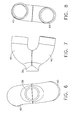
- Figure 5 is a cross-sectional view of one of the fluid fittings of the manifold
- Figure 6 is a plan view of the fitting of Figure 5 ;
- Figure 7 is a side view of the fitting of Figure 5 ;
- Figure 8 is a rear view of the fitting of Figure 5 ;
- Figure 9 is a left side view of the fitting of Figure 5 ;
- Figure 10 is a right side view of the fitting of Figure 5 .
- Figure 1 depicts an exemplary gas turbine engine 10 having a fan 12, a low pressure compressor or “booster” 14 and a low pressure turbine (“LPT") 16 collectively referred to as a “low pressure system”, and a high pressure compressor ("HPC”) 18, a combustor 20, and a high pressure turbine (“HPT”) 22, collectively referred to as a “gas generator” or “core”.
- LPT low pressure turbine
- HPC high pressure compressor
- HPT high pressure turbine
- core gas generator
- While the illustrated engine 10 is a high-bypass turbofan engine, the principles described herein are equally applicable to turboprop, turbojet, and turboshaft engines, as well as turbine engines used for other vehicles or in stationary applications. The principles of this invention are also equally applicable to other fields where a vibration-resistant fluid manifold is required.
- the combustor 20 includes a radial array of fuel nozzles 24 which are coupled to a manifold 26 surrounding the combustor 20.
- pressurized fuel is fed to the manifold 26 by a fuel metering system such as a hydromechanical unit, FMU, PMU, or FADEC system of a known type (not shown).
- the fuel is then distributed by the manifold 26 to the individual fuel nozzles 24.
- the illustrated example shows a single-stage manifold and fuel nozzles, but it will be understood that the principles of the present invention are applicable to multi-circuit systems as well.
- the manifold 26 is shown in more detail in Figure 2 .
- the casing 28 of the combustor 20 can be seen with the inlet stems 30 of the fuel nozzles 24 protruding therefrom.
- Each inlet stem 30 incorporates an inlet fitting 32 of a known type.
- the nozzle inlet stems 30 penetrate the case 28 in a generally radial direction, and the inlet fittings 32 extend in a generally axial direction.
- Coupled to each inlet fitting 32 is a manifold fitting 34.
- the manifold fittings 34 are interconnected by tubes 36.
- each tube 36 is generally "C"-shaped when seen in plan view, and has a constant radius of curvature.
- One or more feed tubes 37 are coupled to the manifold 26 and serve to allow fuel flow into the manifold 26 from a fuel metering and control system of a conventional type (not shown). Most typically the manifold 26 and its constituent components would be made from a metallic alloy, such as an iron- or nickel-based alloy.
- FIGS. 5-10 illustrate one of the manifold fittings 34 in more detail.
- the manifold fitting 34 is generally "Y"-shaped with a tubular central neck 38 and two spaced-apart, generally parallel tubular arms 40 extending therefrom.
- tubular denotes a member which has a wall that encloses a volume for fluid flow therethrough and does not necessarily imply a structure that has a purely circular cross-section or a constant wall thickness.
- the neck 38 is connected to a coupling 42.
- the coupling 42 includes a tubular inner member 44 having a first end 46 connected to the neck 38, and a second end which defines a seat 48.
- the seat 48 receives a ball-nose 50 of the inlet fitting 32 which has a shape complementary to the seat 48.
- a groove 53 is formed in the cylindrical surface of the inlet fitting 32 adjacent the ball-nose 50 and receives a resilient sealing element 55, which seals against the inner member 44.
- the sealing element 55 is an O-ring.
- the outer surface of the inner member 44 includes an annular shoulder 51.
- a collar 52 surrounds the inner member 44 and includes an annular, radially-inwardly-extending flange 54 that engages the shoulder 50.
- the interior of the collar 52 includes threads 56 that engage mating threads 57 of the inlet fitting 32.
- the exterior of the collar 52 is formed into polygonal flats or other suitable wrenching surfaces 60.
- Other types of coupling configurations could be used to couple the manifold fitting 34 to the inlet fitting 32 so long as they provide a leak-free joint.
- the tubes 36 are continuously curved so as to form a "U" or "C" shape.
- the tubes 36 have a constant radius of curvature, but this aspect may be varied as desired to suit a particular application.
- Each tube 36 has opposed ends 58 which are connected to the arms 40 of adjacent manifold fittings 34.
- the tubes 36 may be connected to the manifold fittings 34 in any manner that provides a secure, leak-free joint, for example by the use of thermal or mechanical bonding, adhesives, or mechanical joints or fasteners.
- the tubes 36 form butt joints 62 (see Figure 5 ) with the manifold fittings 34 that are brazed or welded together in a known manner.
- the manifold configuration is "modular" in the sense that a single type of manifold fitting 34 may be coupled to the inlet stems 30 in a variety of different angular orientations and then interconnected with tubes 36 suitable for the selected orientation.
- a designer may effectively increase or decrease the tubing length between neighboring fuel nozzles 24, with the result of changing or "tuning" the manifold's natural frequency.
- Smaller engines generally have a higher frequency of operation, and generally experience less total thermal growth. Larger engines generally have a lower frequency of operation, and generally experience more total thermal growth.
- the ability to tune the manifold's natural frequency allows it to be designed to each engine's specific needs, without the typical systemic redesign seen in the prior art when comparing one engine model to another.
- Figure 3 shows a portion of the manifold 26 with the manifold fittings 34 rotated or "clocked" to a first angular orientation.
- an arrow depicts the plane in which the arms 40 lie.
- the lateral spacing between the connected arms 40 of two adjacent fittings 34, denoted "S1” is relatively small and the radius of the tube 36 which interconnects the arms 40, denoted "Rl”, is relatively small as well.
- the first natural frequency of the manifold 26 is relatively high. Because the tube 36 spans a relatively short point-to-point distance as compared to prior art designs, there is no need for a separate bracket to mount the tubes 36 to the casing 28.
- Figure 4 shows a portion of a manifold 26' assembled using manifold fittings 34 of identical construction to those shown in Figure 3 .
- the manifold fittings 34 in Figure 4 are rotated or "clocked” to a second angular orientation.
- An arrow depicts the plane in which the arms 40 lie, which is about 60 degrees away from the position shown in Figure 3 .
- the lateral spacing between connected fitting arms 40 denoted "S2”
- the tube 36' which interconnects the arms 40 is relatively larger than the tubes 36 as well.
- the radius R2 of the tube 36' may be about 1.25 times the radius R1 of the tube 36.
- the first natural frequency of the manifold 26' is computed to be about 25% lower than that of the manifold 26.
- the stress induced by thermal loading on manifold 26' with a tube radius of R2 is computed to be about 15% lower in magnitude than the stress induced by thermal loading on manifold 26 with a tube radius of R1.
- the position of the manifold fittings 34 is infinitely variable as dictated by design requirements.
- the manifold's vibration characteristics would be analyzed, for example using a tool such as finite element analysis software, and then a fitting orientation and tube radius would be selected based on the required natural frequency.
- the design process is vastly simplified compared to the prior art because the manifold fittings 34 are common to many different manifolds 26.
- the tubes 36 may be produced in one or more "stock" lengths corresponding to several default orientations of the manifold fittings 34.
- the fluid manifold 26 described herein has several advantages over a conventional design. Depending on the specific configuration, the manifold 26 may contain as few as one-tenth as many parts as prior art manifold system designs. It may weigh only about half as much as a prior art manifold system and has a reduced part envelope. Design cycle time will also be decreased because of the simplified nature of the design.
- the foregoing has described a frequency-tunable fluid manifold. While specific embodiments of the present invention have been described, it will be apparent to those skilled in the art that various modifications thereto can be made without departing from the scope of the invention. Accordingly, the foregoing description of the preferred embodiment of the invention and the best mode for practicing the invention are provided for the purpose of illustration only and not for the purpose of limitation.
Landscapes
- Engineering & Computer Science (AREA)
- Chemical & Material Sciences (AREA)
- Combustion & Propulsion (AREA)
- Mechanical Engineering (AREA)
- General Engineering & Computer Science (AREA)
- Supports For Pipes And Cables (AREA)
- Fuel-Injection Apparatus (AREA)
- Turbine Rotor Nozzle Sealing (AREA)
- Quick-Acting Or Multi-Walled Pipe Joints (AREA)
Abstract
Description
- This invention relates generally to fluid handling, and more particularly to apparatus and methods for fluid manifolds in gas turbine engines.
- A gas turbine engine includes a turbomachinery core having a high pressure compressor, a combustor, and a high pressure turbine in serial flow relationship. The core is operable in a known manner to generate a primary gas flow. Depending on the engine's configuration, the core may be combined with a fan and low pressure turbine system to generate propulsive thrust, or with a work turbine to extract mechanical energy and turn a driveshaft or propeller.
- In conventional gas turbine engines, fuel is introduced to the combustor through an array of fuel nozzles which are coupled to an external manifold surrounding the combustor. In operation, pressurized fuel is fed to the manifold. The manifold then distributes the pressurized fuel to the individual fuel nozzles. Such manifolds are commonly manufactured from various tubes and fittings, and are secured to the combustor with brackets and other mounting hardware. Such manifolds experience significant vibration during engine operation.
- Thermal growth is a critical design criterion for these fuel manifolds. The cases that support the fuel nozzles grow as the engine warms, but the temperature of the fuel in the manifold stays relatively cool. This temperature difference, coupled with the different material growth rates of various components, creates a thermal loading on the manifold. To avoid fatigue failure, the manifold's properties such as stiffness, damping, etc. must be designed so as to avoid excitation of one or more of the manifold's natural frequencies within the engine operating range while providing proper flexibility for thermal growth.
- These manifolds are unique to each specific engine model. This requires a substantial design effort and testing iterations, leading to high engineering costs. Furthermore, the typical geometry and large part count leads to relatively high system weights.
- These and other shortcomings of the prior art are addressed by the present invention, which provides a frequency-tunable fluid manifold apparatus.
- According to one aspect of the invention, a fluid manifold apparatus includes:
- (a) an array of spaced-apart manifold fittings, each manifold fitting aligned in a predetermined angular orientation. Each manifold fitting includes: (i) a tubular neck; (ii) a pair of spaced-apart tubular arms extending away from a first end of the neck; and (iii) a coupling connected to a second end of the neck; and (b) a plurality of curved tubes, each tube being coupled to one arm of each of two adjacent manifold fittings.
- According to another aspect of the invention, a method of assembling a fluid manifold includes: (a) providing an array of spaced-apart manifold fittings, each manifold fitting having: (i) a tubular neck; (ii) a pair of spaced-apart tubular arms extending away from a first end of the neck; and (iii) a coupling connected to a second end of the neck; (b) placing each manifold fitting in a predetermined angular orientation; and (c) providing a plurality of curved tubes, and coupling one end of each tube to one arm of each of two adjacent manifold fittings; (d) such that the assembled manifold has a predetermined first natural frequency.
- The invention may be best understood by reference to the following description taken in conjunction with the accompanying drawing figures in which:
-
Figure 1 is a schematic half-sectional view of a gas turbine engine incorporating a fluid manifold constructed in accordance with an aspect of the present invention; -
Figure 2 is a partial perspective view of a combustor of the engine ofFigure 1 , showing a fluid manifold mounted thereto; -
Figure 3 is a plan view of the manifold shown inFigure 2 , with fluid fittings installed in a first position; -
Figure 4 is a plan view of the manifold shown inFigure 2 , with fluid fittings installed in a second position; -
Figure 5 is a cross-sectional view of one of the fluid fittings of the manifold; -
Figure 6 is a plan view of the fitting ofFigure 5 ; -
Figure 7 is a side view of the fitting ofFigure 5 ; -
Figure 8 is a rear view of the fitting ofFigure 5 ; -
Figure 9 is a left side view of the fitting ofFigure 5 ; and -
Figure 10 is a right side view of the fitting ofFigure 5 . - Referring to the drawings wherein identical reference numerals denote the same elements throughout the various views,
Figure 1 depicts an exemplarygas turbine engine 10 having a fan 12, a low pressure compressor or "booster" 14 and a low pressure turbine ("LPT") 16 collectively referred to as a "low pressure system", and a high pressure compressor ("HPC") 18, a combustor 20, and a high pressure turbine ("HPT") 22, collectively referred to as a "gas generator" or "core". Together, the high and low pressure systems are operable in a known manner to generate a primary or core flow as well as a fan flow or bypass flow. While the illustratedengine 10 is a high-bypass turbofan engine, the principles described herein are equally applicable to turboprop, turbojet, and turboshaft engines, as well as turbine engines used for other vehicles or in stationary applications. The principles of this invention are also equally applicable to other fields where a vibration-resistant fluid manifold is required. - The combustor 20 includes a radial array of
fuel nozzles 24 which are coupled to amanifold 26 surrounding the combustor 20. In operation, pressurized fuel is fed to themanifold 26 by a fuel metering system such as a hydromechanical unit, FMU, PMU, or FADEC system of a known type (not shown). The fuel is then distributed by themanifold 26 to theindividual fuel nozzles 24. The illustrated example shows a single-stage manifold and fuel nozzles, but it will be understood that the principles of the present invention are applicable to multi-circuit systems as well. - The
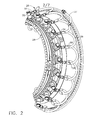
manifold 26 is shown in more detail inFigure 2 . Thecasing 28 of the combustor 20 can be seen with the inlet stems 30 of thefuel nozzles 24 protruding therefrom. Eachinlet stem 30 incorporates aninlet fitting 32 of a known type. In the illustrated example, the nozzle inlet stems 30 penetrate thecase 28 in a generally radial direction, and theinlet fittings 32 extend in a generally axial direction. Coupled to eachinlet fitting 32 is amanifold fitting 34. Themanifold fittings 34 are interconnected bytubes 36. In the illustrated example eachtube 36 is generally "C"-shaped when seen in plan view, and has a constant radius of curvature. One ormore feed tubes 37 are coupled to themanifold 26 and serve to allow fuel flow into themanifold 26 from a fuel metering and control system of a conventional type (not shown). Most typically themanifold 26 and its constituent components would be made from a metallic alloy, such as an iron- or nickel-based alloy. -
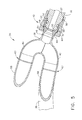
Figures 5-10 illustrate one of themanifold fittings 34 in more detail. Themanifold fitting 34 is generally "Y"-shaped with a tubularcentral neck 38 and two spaced-apart, generally paralleltubular arms 40 extending therefrom. As used herein, the term "tubular" denotes a member which has a wall that encloses a volume for fluid flow therethrough and does not necessarily imply a structure that has a purely circular cross-section or a constant wall thickness. Theneck 38 is connected to acoupling 42. - The
coupling 42 includes a tubularinner member 44 having afirst end 46 connected to theneck 38, and a second end which defines aseat 48. When connected to theinlet stem 30, theseat 48 receives a ball-nose 50 of the inlet fitting 32 which has a shape complementary to theseat 48. Agroove 53 is formed in the cylindrical surface of the inlet fitting 32 adjacent the ball-nose 50 and receives aresilient sealing element 55, which seals against theinner member 44. In the illustrated example thesealing element 55 is an O-ring. The outer surface of theinner member 44 includes anannular shoulder 51. Acollar 52 surrounds theinner member 44 and includes an annular, radially-inwardly-extendingflange 54 that engages theshoulder 50. The interior of thecollar 52 includesthreads 56 that engagemating threads 57 of the inlet fitting 32. The exterior of thecollar 52 is formed into polygonal flats or othersuitable wrenching surfaces 60. Other types of coupling configurations could be used to couple themanifold fitting 34 to the inlet fitting 32 so long as they provide a leak-free joint. - As best seen in
Figure 3 , thetubes 36 are continuously curved so as to form a "U" or "C" shape. In this example thetubes 36 have a constant radius of curvature, but this aspect may be varied as desired to suit a particular application. Eachtube 36 has opposed ends 58 which are connected to thearms 40 of adjacentmanifold fittings 34. Thetubes 36 may be connected to themanifold fittings 34 in any manner that provides a secure, leak-free joint, for example by the use of thermal or mechanical bonding, adhesives, or mechanical joints or fasteners. As illustrated, thetubes 36 form butt joints 62 (seeFigure 5 ) with themanifold fittings 34 that are brazed or welded together in a known manner. - The manifold configuration is "modular" in the sense that a single type of
manifold fitting 34 may be coupled to the inlet stems 30 in a variety of different angular orientations and then interconnected withtubes 36 suitable for the selected orientation. By "twisting" the manifold fitting 34 clockwise or counter-clockwise from a nominal position, a designer may effectively increase or decrease the tubing length between neighboringfuel nozzles 24, with the result of changing or "tuning" the manifold's natural frequency. Smaller engines generally have a higher frequency of operation, and generally experience less total thermal growth. Larger engines generally have a lower frequency of operation, and generally experience more total thermal growth. The ability to tune the manifold's natural frequency allows it to be designed to each engine's specific needs, without the typical systemic redesign seen in the prior art when comparing one engine model to another. - For example,
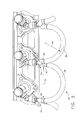
Figure 3 shows a portion of the manifold 26 with themanifold fittings 34 rotated or "clocked" to a first angular orientation. For the sake of illustration, an arrow depicts the plane in which thearms 40 lie. In this position, the lateral spacing between theconnected arms 40 of twoadjacent fittings 34, denoted "S1", is relatively small and the radius of thetube 36 which interconnects thearms 40, denoted "Rl", is relatively small as well. As a result, the first natural frequency of the manifold 26 is relatively high. Because thetube 36 spans a relatively short point-to-point distance as compared to prior art designs, there is no need for a separate bracket to mount thetubes 36 to thecasing 28. -
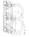
Figure 4 shows a portion of a manifold 26' assembled usingmanifold fittings 34 of identical construction to those shown inFigure 3 . Themanifold fittings 34 inFigure 4 are rotated or "clocked" to a second angular orientation. An arrow depicts the plane in which thearms 40 lie, which is about 60 degrees away from the position shown inFigure 3 . In this position, the lateral spacing between connectedfitting arms 40, denoted "S2", is larger than the spacing S1, and the tube 36' which interconnects thearms 40 is relatively larger than thetubes 36 as well. For example, the radius R2 of the tube 36' may be about 1.25 times the radius R1 of thetube 36. As a result, the first natural frequency of the manifold 26' is computed to be about 25% lower than that of the manifold 26. In this example, the stress induced by thermal loading on manifold 26' with a tube radius of R2 is computed to be about 15% lower in magnitude than the stress induced by thermal loading onmanifold 26 with a tube radius of R1. The position of themanifold fittings 34 is infinitely variable as dictated by design requirements. - As part of the design process, the manifold's vibration characteristics would be analyzed, for example using a tool such as finite element analysis software, and then a fitting orientation and tube radius would be selected based on the required natural frequency. The design process is vastly simplified compared to the prior art because the
manifold fittings 34 are common to manydifferent manifolds 26. Thetubes 36 may be produced in one or more "stock" lengths corresponding to several default orientations of themanifold fittings 34. - The
fluid manifold 26 described herein has several advantages over a conventional design. Depending on the specific configuration, the manifold 26 may contain as few as one-tenth as many parts as prior art manifold system designs. It may weigh only about half as much as a prior art manifold system and has a reduced part envelope. Design cycle time will also be decreased because of the simplified nature of the design.
The foregoing has described a frequency-tunable fluid manifold. While specific embodiments of the present invention have been described, it will be apparent to those skilled in the art that various modifications thereto can be made without departing from the scope of the invention. Accordingly, the foregoing description of the preferred embodiment of the invention and the best mode for practicing the invention are provided for the purpose of illustration only and not for the purpose of limitation.
Claims (15)
- A fluid manifold apparatus, comprising:(a) an array of spaced-apart manifold fittings (34), each manifold fitting (34) aligned in a predetermined angular orientation, where each manifold fitting (34) comprises:(i) a generally tubular neck (38);(ii) a pair of spaced-apart generally tubular arms (40) extending away from a first end of the neck (38); and(iii) a coupling (42) connected to a second end of the neck (38); and(b) a plurality of curved tubes (36), each tube (36) being coupled to one arm of each of two adjacent manifold fittings (34).
- The apparatus of claim 1, wherein the coupling (42) comprises an inner member (44) and a collar (52) surrounding the inner member (44).
- The apparatus of claim 2, wherein the collar (52) is threaded and includes an annular flange (54) which bears against a shoulder (51) of the inner member (44).
- The apparatus of any preceding claim, wherein each of the couplings (42) is connected to a fuel nozzle inlet stem (30).
- The apparatus of claim 4 wherein each inlet stem (30) includes an inlet fitting which includes:(a) a ball-nose (50) having a shape complementary to a seat defined by the inner member (44) of the coupling (42); and(b) a resilient sealing element (55) disposed in a groove in an outer surface of the inlet fitting.
- The apparatus of claim 4 or claim 5, wherein each of the fuel nozzle inlet stem (30)s is part of a fuel nozzle that is mounted to a combustor of a gas turbine engine.
- The apparatus of any preceding claim, wherein each tube (36) has a constant radius of curvature.
- The apparatus of any preceding claim, wherein the ends of the tubes (36) are rigidly coupled to the arms (40) of the manifold fittings (34).
- A method of assembling a fluid manifold, comprising:(a) providing an array of spaced-apart manifold fittings (34), each manifold fitting (34) comprising:(i) a generally tubular neck (38);(ii) a pair of spaced-apart generally tubular arms (40) extending away from a first end of the neck (38); and(iii) a coupling (42) connected to a second end of the neck (38); and(b) placing each manifold fitting (34) in a predetermined angular orientation; and(c) providing a plurality of curved tubes (36), and coupling one end of each tube (36) to one arm of each of two adjacent manifold fittings (34);(d) such that the assembled manifold has a predetermined first natural frequency.
- The method of claim 9 wherein the coupling (42) comprises an inner member (44) and a collar (52) surrounding the inner member (44).
- The method of claim 10 wherein the collar (52) is threaded and includes an annular flange (54) which bears against a shoulder (51) of the inner member (44).
- The method of claim 9 further comprising connecting each of the couplings (42) to a fuel nozzle inlet stem (30).
- The method of claim 12 wherein each inlet stem (30) includes an inlet fitting which includes:(a) a ball-nose (50) having a shape complementary to a seat defined by the inner member (44) of the coupling (42); and(b) a resilient sealing element (55) disposed in a groove in an outer surface of the inlet fitting.
- The method of claim 12 wherein each of the fuel nozzle inlet stem (30)s is part of a fuel nozzle that is mounted to a combustor of a gas turbine engine.
- The method of claim 9 wherein the ends of the tubes (36) are rigidly coupled to the arms (40) of the manifold fittings (34).
Applications Claiming Priority (1)
| Application Number | Priority Date | Filing Date | Title |
|---|---|---|---|
| US12/650,972 US8769954B2 (en) | 2009-12-31 | 2009-12-31 | Frequency-tunable bracketless fluid manifold |
Publications (2)
| Publication Number | Publication Date |
|---|---|
| EP2341231A2 true EP2341231A2 (en) | 2011-07-06 |
| EP2341231A3 EP2341231A3 (en) | 2017-12-13 |
Family
ID=43661806
Family Applications (1)
| Application Number | Title | Priority Date | Filing Date |
|---|---|---|---|
| EP10195954.2A Withdrawn EP2341231A3 (en) | 2009-12-31 | 2010-12-20 | Frequency-tunable bracketless fluid manifold |
Country Status (4)
| Country | Link |
|---|---|
| US (2) | US8769954B2 (en) |
| EP (1) | EP2341231A3 (en) |
| JP (1) | JP5802386B2 (en) |
| CA (1) | CA2725856A1 (en) |
Cited By (2)
| Publication number | Priority date | Publication date | Assignee | Title |
|---|---|---|---|---|
| US9790862B2 (en) | 2014-05-07 | 2017-10-17 | Rolls-Royce Plc | Fuel manifold and fuel injector arrangement for a combustion chamber |
| US10174948B2 (en) | 2015-02-25 | 2019-01-08 | Rolls-Royce Plc | Combustion staging system |
Families Citing this family (15)
| Publication number | Priority date | Publication date | Assignee | Title |
|---|---|---|---|---|
| US9803498B2 (en) * | 2012-10-17 | 2017-10-31 | United Technologies Corporation | One-piece fuel nozzle for a thrust engine |
| US9267689B2 (en) | 2013-03-04 | 2016-02-23 | Siemens Aktiengesellschaft | Combustor apparatus in a gas turbine engine |
| US20140261797A1 (en) * | 2013-03-14 | 2014-09-18 | United Technologies Corporation | Tube fitting having integrated tee fitting |
| US9322558B2 (en) | 2013-06-27 | 2016-04-26 | Siemens Aktiengesellschaft | Combustor apparatus in a gas turbine engine |
| GB201313034D0 (en) * | 2013-07-22 | 2013-09-04 | Rolls Royce Plc | A fuel manifold and fuel injector arrangement for a combustion chamber |
| GB201401581D0 (en) | 2014-01-30 | 2014-03-19 | Rolls Royce Plc | A fuel manifold and fuel injector arrangement |
| US10364751B2 (en) * | 2015-08-03 | 2019-07-30 | Delavan Inc | Fuel staging |
| US10087845B2 (en) | 2015-11-30 | 2018-10-02 | General Electric Company | Pressure damping device for fuel manifold |
| US10329941B2 (en) * | 2016-05-06 | 2019-06-25 | United Technologies Corporation | Impingement manifold |
| US11092084B2 (en) | 2016-05-26 | 2021-08-17 | General Electric Company | Fuel delivery system for a gas turbine engine |
| US11506125B2 (en) | 2018-08-01 | 2022-11-22 | General Electric Company | Fluid manifold assembly for gas turbine engine |
| CN113969837B (en) * | 2020-07-24 | 2026-01-23 | 通用电气技术有限公司 | Improved fuel distribution manifold |
| US11629641B2 (en) | 2020-09-29 | 2023-04-18 | General Electric Company | Fuel distribution manifold |
| CN114151827B (en) * | 2022-02-08 | 2022-07-08 | 中国航发四川燃气涡轮研究院 | Flexible fuel manifold integrated with fuel nozzle |
| WO2025239137A1 (en) * | 2024-05-14 | 2025-11-20 | 三菱重工業株式会社 | Fuel manifold, gas turbine combustor, and gas turbine |
Family Cites Families (30)
| Publication number | Priority date | Publication date | Assignee | Title |
|---|---|---|---|---|
| US3516252A (en) * | 1969-02-26 | 1970-06-23 | United Aircraft Corp | Fuel manifold system |
| US4028888A (en) * | 1974-05-03 | 1977-06-14 | Norwalk-Turbo Inc. | Fuel distribution manifold to an annular combustion chamber |
| US3945759A (en) | 1974-10-29 | 1976-03-23 | General Electric Company | Bleed air manifold |
| US4155681A (en) | 1977-02-14 | 1979-05-22 | General Electric Company | Manifold protection system |
| US4214851A (en) | 1978-04-20 | 1980-07-29 | General Electric Company | Structural cooling air manifold for a gas turbine engine |
| US4903478A (en) | 1987-06-25 | 1990-02-27 | General Electric Company | Dual manifold fuel system |
| US5036657A (en) | 1987-06-25 | 1991-08-06 | General Electric Company | Dual manifold fuel system |
| US4862693A (en) * | 1987-12-10 | 1989-09-05 | Sundstrand Corporation | Fuel injector for a turbine engine |
| US5119636A (en) * | 1989-12-21 | 1992-06-09 | Sundstrand Corporation | Fuel injector for a turbine engine |
| US5100291A (en) | 1990-03-28 | 1992-03-31 | General Electric Company | Impingement manifold |
| US5231833A (en) | 1991-01-18 | 1993-08-03 | General Electric Company | Gas turbine engine fuel manifold |
| US5168698A (en) * | 1991-04-22 | 1992-12-08 | General Electric Company | Fuel manifold system for gas turbine engines |
| US5211005A (en) * | 1992-04-16 | 1993-05-18 | Avco Corporation | High density fuel injection manifold |
| US5271711A (en) | 1992-05-11 | 1993-12-21 | General Electric Company | Compressor bore cooling manifold |
| US5241289A (en) | 1992-07-24 | 1993-08-31 | General Electric Company | Exhaust arc gas manifold |
| US5263314A (en) * | 1992-09-28 | 1993-11-23 | General Motors Corporation | Fuel leakage protection system for gas turbine engine |
| US5399066A (en) | 1993-09-30 | 1995-03-21 | General Electric Company | Integral clearance control impingement manifold and environmental shield |
| US5848525A (en) | 1996-08-30 | 1998-12-15 | General Electric Company | Fuel manifold staging valve |
| US5771696A (en) | 1996-10-21 | 1998-06-30 | General Electric Company | Internal manifold fuel injection assembly for gas turbine |
| US5890746A (en) * | 1996-12-18 | 1999-04-06 | General Electric Company | Cooled and wetted redundant seal tube fitting |
| US6367240B1 (en) | 1998-06-22 | 2002-04-09 | General Electric Company | Air manifold system |
| US6339924B1 (en) * | 1999-12-20 | 2002-01-22 | General Electric Company | Method and apparatus for encapsulating gas turbine engine fuel connections |
| US6512192B1 (en) | 2001-10-02 | 2003-01-28 | General Electric Company | Exhaust arc gas manifold |
| US6965185B1 (en) | 2004-05-26 | 2005-11-15 | General Electric Company | Variable pitch manifold for rotor cooling in an electrical machine |
| US7090462B2 (en) | 2004-08-18 | 2006-08-15 | General Electric Company | Compressor bleed air manifold for blade clearance control |
| US7374396B2 (en) | 2005-02-28 | 2008-05-20 | General Electric Company | Bolt-on radial bleed manifold |
| FR2886370B1 (en) * | 2005-05-27 | 2008-10-10 | Snecma Moteurs Sa | DEVICE FOR CONNECTING TWO ELEMENTS SUCH AS A FUEL SUPPLY LINE AND AN INJECTOR |
| US7568344B2 (en) * | 2005-09-01 | 2009-08-04 | Frait & Whitney Canada Corp. | Hydrostatic flow barrier for flexible fuel manifold |
| JP4764392B2 (en) * | 2007-08-29 | 2011-08-31 | 三菱重工業株式会社 | Gas turbine combustor |
| US7992390B2 (en) * | 2008-09-23 | 2011-08-09 | Pratt & Whitney Canada Corp. | External rigid fuel manifold |
-
2009
- 2009-12-31 US US12/650,972 patent/US8769954B2/en active Active
-
2010
- 2010-12-16 CA CA2725856A patent/CA2725856A1/en not_active Abandoned
- 2010-12-20 EP EP10195954.2A patent/EP2341231A3/en not_active Withdrawn
- 2010-12-20 JP JP2010282653A patent/JP5802386B2/en not_active Expired - Fee Related
-
2014
- 2014-07-07 US US14/324,952 patent/US20140310959A1/en not_active Abandoned
Non-Patent Citations (1)
| Title |
|---|
| None |
Cited By (2)
| Publication number | Priority date | Publication date | Assignee | Title |
|---|---|---|---|---|
| US9790862B2 (en) | 2014-05-07 | 2017-10-17 | Rolls-Royce Plc | Fuel manifold and fuel injector arrangement for a combustion chamber |
| US10174948B2 (en) | 2015-02-25 | 2019-01-08 | Rolls-Royce Plc | Combustion staging system |
Also Published As
| Publication number | Publication date |
|---|---|
| JP2011137452A (en) | 2011-07-14 |
| CA2725856A1 (en) | 2011-06-30 |
| US8769954B2 (en) | 2014-07-08 |
| JP5802386B2 (en) | 2015-10-28 |
| US20110154824A1 (en) | 2011-06-30 |
| US20140310959A1 (en) | 2014-10-23 |
| EP2341231A3 (en) | 2017-12-13 |
Similar Documents
| Publication | Publication Date | Title |
|---|---|---|
| US8769954B2 (en) | Frequency-tunable bracketless fluid manifold | |
| US10753279B2 (en) | Gas turbine engine mid turbine frame bearing support | |
| CA2926072C (en) | Thermally-coupled fuel manifold | |
| CN109196203B (en) | Fuel Delivery Systems for Gas Turbine Engines | |
| US8978388B2 (en) | Load member for transition duct in turbine system | |
| US9140453B2 (en) | Fuel manifold with jumper tubes | |
| EP3358140B1 (en) | Fitting for multiwall tube | |
| US20150211418A1 (en) | Fuel manifold and fuel injector arrangement | |
| EP3597869B1 (en) | Sealing configuration for a transfer tube assembly to reduce air leakage | |
| EP2942509A1 (en) | A fuel manifold and fuel injector arrangment for a combustion chamber | |
| US10132244B2 (en) | Fuel manifold for a gas turbine engine | |
| EP3097292A2 (en) | Additive manufactured non-round, septum tied, conformal high pressure tubing | |
| EP4086437A1 (en) | Vane system with continuous support ring | |
| CN101429876B (en) | Connection of radial struts to a circular casing by pins and spacers | |
| EP2420652A2 (en) | Manifold mounting arrangement | |
| CN116490729A (en) | Combustion modules for turbines | |
| US7921649B2 (en) | Mode suppression shape for beams | |
| US12385581B2 (en) | Fastening assembly | |
| EP3819479B1 (en) | Mechanical attachment scheme for isogrid ducts | |
| CA2693528C (en) | Nozzle repair to reduce fretting | |
| EP3055510A1 (en) | Ducts for engines | |
| WO2015052466A1 (en) | Ducts for engines |
Legal Events
| Date | Code | Title | Description |
|---|---|---|---|
| PUAI | Public reference made under article 153(3) epc to a published international application that has entered the european phase |
Free format text: ORIGINAL CODE: 0009012 |
|
| AK | Designated contracting states |
Kind code of ref document: A2 Designated state(s): AL AT BE BG CH CY CZ DE DK EE ES FI FR GB GR HR HU IE IS IT LI LT LU LV MC MK MT NL NO PL PT RO RS SE SI SK SM TR |
|
| AX | Request for extension of the european patent |
Extension state: BA ME |
|
| PUAL | Search report despatched |
Free format text: ORIGINAL CODE: 0009013 |
|
| AK | Designated contracting states |
Kind code of ref document: A3 Designated state(s): AL AT BE BG CH CY CZ DE DK EE ES FI FR GB GR HR HU IE IS IT LI LT LU LV MC MK MT NL NO PL PT RO RS SE SI SK SM TR |
|
| AX | Request for extension of the european patent |
Extension state: BA ME |
|
| RIC1 | Information provided on ipc code assigned before grant |
Ipc: F02C 7/22 20060101AFI20171106BHEP |
|
| STAA | Information on the status of an ep patent application or granted ep patent |
Free format text: STATUS: THE APPLICATION IS DEEMED TO BE WITHDRAWN |
|
| 18D | Application deemed to be withdrawn |
Effective date: 20180614 |