EP2340980A1 - Parking assistant system - Google Patents
Parking assistant system Download PDFInfo
- Publication number
- EP2340980A1 EP2340980A1 EP09425546A EP09425546A EP2340980A1 EP 2340980 A1 EP2340980 A1 EP 2340980A1 EP 09425546 A EP09425546 A EP 09425546A EP 09425546 A EP09425546 A EP 09425546A EP 2340980 A1 EP2340980 A1 EP 2340980A1
- Authority
- EP
- European Patent Office
- Prior art keywords
- parking
- manoeuvre
- vehicle
- parameters
- simulation
- Prior art date
- Legal status (The legal status is an assumption and is not a legal conclusion. Google has not performed a legal analysis and makes no representation as to the accuracy of the status listed.)
- Granted
Links
- 238000004088 simulation Methods 0.000 claims abstract description 43
- 238000001514 detection method Methods 0.000 claims description 12
- 238000000034 method Methods 0.000 description 4
- 238000010586 diagram Methods 0.000 description 3
- 238000006073 displacement reaction Methods 0.000 description 3
- 230000000007 visual effect Effects 0.000 description 2
- 230000004913 activation Effects 0.000 description 1
- 238000010276 construction Methods 0.000 description 1
- 230000000694 effects Effects 0.000 description 1
- 230000003287 optical effect Effects 0.000 description 1
- 230000035484 reaction time Effects 0.000 description 1
- 230000005236 sound signal Effects 0.000 description 1
- 230000026676 system process Effects 0.000 description 1
- 238000002604 ultrasonography Methods 0.000 description 1
Images




Classifications
-
- B—PERFORMING OPERATIONS; TRANSPORTING
- B62—LAND VEHICLES FOR TRAVELLING OTHERWISE THAN ON RAILS
- B62D—MOTOR VEHICLES; TRAILERS
- B62D15/00—Steering not otherwise provided for
- B62D15/02—Steering position indicators ; Steering position determination; Steering aids
- B62D15/027—Parking aids, e.g. instruction means
- B62D15/0285—Parking performed automatically
-
- B—PERFORMING OPERATIONS; TRANSPORTING
- B62—LAND VEHICLES FOR TRAVELLING OTHERWISE THAN ON RAILS
- B62D—MOTOR VEHICLES; TRAILERS
- B62D15/00—Steering not otherwise provided for
- B62D15/02—Steering position indicators ; Steering position determination; Steering aids
- B62D15/027—Parking aids, e.g. instruction means
- B62D15/028—Guided parking by providing commands to the driver, e.g. acoustically or optically
Definitions
- the subject of the present invention is a parking-assistant system for assisting the driver in a manoeuvre in reverse for parking the vehicle at the roadside, parallel to the direction of the road, in a parking space between a first obstacle and a second obstacle that define, respectively, the front limit and the rear limit of said space with respect to the body of the vehicle.
- the subject of the invention is a system comprising detection means for detecting the scene external to the vehicle, and processing means designed to generate control signals for following a parking path.
- the object of the present invention is to provide a simple and reliable system that will enable parking in the least possible number of manoeuvres.
- the detection means of the system are designed for generating signals indicating the scene surrounding the parking space whilst the vehicle proceeds to a start-of-manoeuvre position
- the processing means are designed to generate, when the vehicle has not yet started the parking manoeuvre, a series of signals indicating positions along one and the same reference path for effecting the parking manoeuvre.
- the processing means generate said series according to the following logic:
- the signals indicating the reference positions represent the values assumed by the parameters in the simulation, which are different from the impact values.
- the system processes a sequence of positions for a reference parking manoeuvre.
- Said sequence of positions is processed by simulating exit of the vehicle from the parking space, in the scenario that is reconstructed on the basis of what is detected by the detection means when the vehicle passes in front of the parking space to reach the start-of-manoeuvre position.
- said scenario is reconstructed within a predefined reference system, with respect to which are defined the co-ordinates of the obstacles that delimit the free area of manoeuvre and the parking space.
- the processing means simulate, within said reference system, exit of the vehicle from the parking space, starting from a predefined end-of-parking position, to bring the vehicle into the start-of-parking position that it actually occupies.
- the processing means record the co-ordinates of the positions of the vehicle in which impact with the obstacles does not occur.
- the set of said co-ordinates constitutes the reference path for the manoeuvre to be performed.
- the parking-assistant system During the parking manoeuvre proper, the parking-assistant system generates control signals for following said path.
- the system is able to generate, before the parking manoeuvre is started, a predetermined path for execution of the parking manoeuvre in the lowest possible number of manoeuvres.
- the control effected by the system, during the real parking manoeuvre, is limited to comparing the effective position of the vehicle with respect to the predetermined path and to generating control signals as a function of the deviation detected between them. Said control has somewhat low computational requirements so that the system is quite reliable.
- the predefined end-of-manoeuvre position is identified so that the vehicle is closer to the rear obstacle than to the front one.
- a further embodiment envisages that the processing means execute a querying operation, in which:
- the signals indicating the reference positions that are generated by the processing means represent the values assumed by the parameters in the first, new first, second, and third manoeuvres, which are different from the impact values.
- the parking-assistant system has a control unit 4 and a command unit 5.
- the unit 4 manages the process of generation of the predetermined path and of control of the deviation between the latter and the actual one of the vehicle, whilst the unit 5 governs the steering system of the motor vehicle on the basis of the signals that it receives from the unit 4.
- the unit 5 can, for example, be operatively connected to an electric motor designed to intervene on the steering system for controlling the steering angle of the front axle of the vehicle.
- Figure 4 illustrates an example of block diagram of the control unit 4.
- Said unit comprises a central management block 15, which manages and co-ordinates the operations of blocks 11, 12, 13, 14, 15 and of the user interface 16, which will be described in what follows.
- the central block 15 is connected to a pushbutton that the driver presses when he wishes to park the vehicle. At that point, activation signals 20 are received by block 15, which activates the entire system.
- block 15 signals to the driver, via the interface unit 16 (for example, a display of the on-board control panel or the TFT of the navigation system), that it is possible to carry out the parking manoeuvre in the space identified.
- the position in which the driver stops the vehicle corresponds to the start-of-manoeuvre position illustrated in Figures 1 and 2 .
- block 11 verifies whether said space is sufficient or not for the vehicle in question.
- Block 11 is moreover designed for reconstructing the scenario of the parking manoeuvre to be performed, once the suitable parking space has been identified and the vehicle is in the start-of-manoeuvre position 1, illustrated in Figures 1 and 2 .
- block 11 identifies, within a predefined reference system, the position of the obstacles that delimit the parking space and the free area of manoeuvre. This is obtained via a process of geometrical reconstruction that derives the co-ordinates of the obstacles in the reference system, combining the information on distance of the obstacles, speed, direction, and displacement of the vehicle, which are determined while the vehicle is advancing and "films", via the detection means, the parking scenario.
- block 11 applies safety margins to the co-ordinates calculated, in such a way as to consider an available space and a free area of manoeuvre smaller than the ones detected.
- block 12 Operatively connected to block 11 is block 12, which represents a path-generating block.
- Said block has the function of determining the reference path in the reconstructed parking scenario.
- Said parking path is determined when the vehicle is still stationary in the start-of-manoeuvre position.
- Said path is determined by simulating within the reference system a manoeuvre of exit from the parking space.
- Said exit manoeuvre is simulated, starting from a desired end-of-parking position, for bringing the vehicle up to the start-of-manoeuvre position that it actually occupies.
- the end-of-parking position is defined on the basis of pre-set distances at which it is desired that the vehicle should be located from the rear obstacle and the off-side edge (i.e., closer to the centre of the road) of the parking space.
- Figures 1 and 2 illustrate two different parallel-parking situations.
- the unit 11 reconstructs the geometry for detecting the parking scenario of Figures 1 and 2 , on the basis of the information detected whilst the vehicle passes in front of the parking space, to arrive at the start-of-manoeuvre position 1'.
- Figures 1 and 2 differ inasmuch Figure 1 represents a situation of parallel parking along a rectilinear stretch of road, whilst Figure 2 represents a parallel-parking situation in a curvilinear stretch of road. It should be noted that the system described herein is able to assist the driver in both of the situations illustrated.
- Figures 7 represent a first example of simulation of an exit manoeuvre for a situation of parallel parking along a rectilinear stretch of road.
- the position 1 I illustrated in Figure 7a represents the end-of-manoeuvre position, which is identified by block 12, from which the simulation of the exit manoeuvre is started.
- the initial position 1 I is chosen such that the vehicle will come to be parallel to the line A (shown in Figure 5 ) joining the two off-side corners (i.e., the corners closer to the centre of the road), facing one another, of the front obstacle and of the rear obstacle, respectively.
- block 12 considers a set of significant points of the body of the vehicle, calculating each time for them, during simulation, the co-ordinates within the reference system XY. In one example, starting from the final end-of-parking position 1 I up to the start-of-manoeuvre position 1, block 12 calculates the co-ordinates of all the positions that are, with respect to the previous one, at the distance of a same pre-set angular pitch, which is defined by the rotation of one of the front wheels of the vehicle (so-called "wheel tick").
- first steering angle there is preferably chosen the maximum steering angle of the vehicle.
- the position 1 II is chosen on the basis of the desired distances 1, t at which it is imposed that the body of the vehicle should be located from the obstacles A and B. Further distances between the body of the vehicle and the obstacle B can likewise be considered and controlled.
- the unit 12 each time calculates the new co-ordinates of the corner G, and of all the points considered of the body of the vehicle, and stores the values thereof.
- the points of the body of the vehicle considered can, for example, be the four outermost corners.
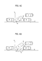
- Figures 6 represent a second example of simulation obtained by block 12 for a situation of parallel parking along a rectilinear stretch of road.
- simulation block 12 considers a set of significant points of the body of the vehicle, calculating each time for them, during the simulation, the co-ordinates within the reference system XY.
- the simulation of the first advance at the first steering angle brings the corner G of the vehicle into impact with the obstacle B.
- Block 12 realizes the occurrence of the impact verifying that the co-ordinates of point G during said manoeuvre assume values corresponding to the co-ordinates of the obstacle B in the reference system XY.
- the co-ordinates of the obstacles A and B have been calculated by block 11 during the geometrical reconstruction of the scenario.
- Block 12 then stores the co-ordinates of the points considered of the body of the vehicle, in the positions assumed as far as the position 1 II , which is the limit of non-impact, illustrated in Figure 6b .
- the unit 12 envisages simulation of a reverse manoeuvre of the vehicle, starting from the position 1 II .
- Said reverse manoeuvre is executed with a second steering angle, of opposite sign with respect to the first steering angle.
- chosen as second steering angle is the maximum steering angle of the vehicle.
- Said reverse manoeuvre brings the corner H of the vehicle, highlighted in Figure 6c , into impact with the wall that delimits the parking space laterally.
- the unit 12 realizes the existence of said circumstance by verifying that the co-ordinates of the corner H assume the values of the co-ordinates of said side wall.
- the unit 12 then stores the co-ordinates of the points considered of the body of the vehicle, in the positions assumed (during reverse), up to the non-impact limit position 1 III , illustrated in Figure 6c .
- the unit 12 envisages simulation of a further manoeuvre of advance at the first steering angle, starting from the position 1 III indicated above, until it reaches the position 1 IV illustrated in Figure 6d .
- the control unit 12 verifies that in the simulation of said further manoeuvre of advance there are no situations of impact so that said manoeuvre can terminate in a pre-set position 1 IV .
- the corners G and H are, for example, at pre-set distances g and h, at which it is imposed that the vehicle should be with respect to the obstacle B, at the end of the further manoeuvre of advance at the first steering angle.
- the unit 12 stores the co-ordinates of the points considered of the body of the vehicle, in the positions that assumed to arrive at the position 1 IV .
- Illustrated in Figure 8 is the path s of said simulation, which is processed by block 12 imposing that it should be tangential to the directions u, v of the vehicle, when the latter occupies, respectively, the position 1 II or 1 IV and the position 1, and verifying that no situation of impact between the vehicle and the obstacle B corresponds thereto.
- block 12 uses polynomial curves, such as fourth-degree Bezier curves, by choosing points of passage whereby impact of the vehicle with the obstacles that define the free area of passage is avoided. It is imposed, for example, that the co-ordinates of the points considered of the body of the vehicle assume the values of the co-ordinates of the free area of passage. For said step, it is particularly advantageous to consider some points of the near side of the body of the vehicle.
- step 21 Determined in step 21 is the geometry for detecting the parking scenario in the predefined reference system.
- step 22 attributed to the parameters indicating the position of the motor vehicle in the reference system XY are values corresponding to the final parking position.
- step 23 is the first manoeuvre of advance at the first steering angle.
- step 24 it is verified whether the parameters indicating the position of the vehicle during said manoeuvre assume values indicating situations of impact with the obstacles.
- step 25 in which a manoeuvre of reverse at a second steering angle of opposite sign with respect to the first is simulated.
- step 23 is again envisaged, in which simulation of a new manoeuvre of advance at the first steering angle is made.
- step 26 in which the manoeuvre of advance at a third steering angle of opposite sign with respect to the first is simulated.
- the path generated with reference to Figures 7 corresponds to a parking manoeuvre in two steps, whereas the path generated with reference to Figures 6 corresponds to a so-called "multi-manoeuvre parking”.
- block 12 is operatively connected to a block 13 for control of the angle of steering of the vehicle.
- Block 13 is likewise operatively connected to a block 14, which is designed to derive the positions assumed by the vehicle in the reference system XY, during the real parking manoeuvre, on the basis of the signals 8, indicating the real conditions of the vehicle, such as speed, direction, and displacement.
- block 14 considers the positions that are assumed by the points of the body of the vehicle that have been already considered by block 12.
- Block 14 generates information on the effective position of the vehicle during the parking manoeuvre and transmits it to the control block 13. The position of the vehicle must be evaluated with respect to the same scenario reconstructed previously.
- Block 14 is hence linked to block 12 in order to be co-ordinated for said scenario, and derive with respect thereto the positions of the vehicle during the manoeuvre. Furthermore, in the example in which the positions considered by block 12 are at distances each with respect to the previous one by a wheel tick, block 14 co-ordinates itself so that it too will consider positions of the vehicle that are at distances each with respect to the previous one by the same wheel tick considered by block 12, starting from the start-of-manoeuvre position 1.
- the system just makes a check on the steering system for following the predetermined path.
- control block 13 is designed to generate commands for governing steering of the vehicle. Said commands are generated on the basis of the deviation found between the predetermined path by block 12 and the positions determined by block 14.
- control signals generated are then sent to block 5 for driving the actuator so that it governs the steering angle of the vehicle.
- said control signals can be converted into instructions for the driver to be displayed on a user interface.
- the real parking manoeuvre is thus executed under the control of block 13, which verifies the deviations of the real path from the predetermined one, and governs corresponding path adjustments in order to follow a real path that corresponds as much as possible to the predetermined one. Since the predetermined path is known in its entirety, in the case of deviation, block 13 is able to envisage the best path, not only for joining up thereto, but also for limiting possible further deviations. For this purpose, block 13 calculates gradual adjustments, which might be followed properly in the manoeuvre.
- block 13 receives signals 6 from the proximity sensors 3 (illustrated in Figure 3 ), as further precaution against impacts both with the obstacles A and B and the wall or obstacle that delimits the parking space laterally and with possible obstacles that are interposed in the area of manoeuvre after the vehicle has reached the start-of-manoeuvre position and the parking scenario has already been reconstructed. In the latter case, block 13 issues signals of acoustic or visual warning to the user interface 16.
- the parking-assistant system envisages automatic control of steering of the vehicle, whilst the driver has control over the accelerator, brake, and direction of travel.
- the user interface 16 has the function of indicating to the driver how to effect the control on said elements.
- multi-manoeuvre parking it is particularly important for the intervention of the driver to be sufficiently timely for the real path to deviate as little as possible from the predetermined one.
- an acoustic emitter is provided, which warns him of the moment at which to intervene.
- the acoustic signal is emitted with a time of advance that takes into account the reaction times of the driver.
- the system envisages a Kalman filter of the type illustrated in Figure 10 , where designated by 30 is a prediction block, which receives at input signals 31, 32, 33 indicating, respectively, the speed of the vehicle, the steering angle, and the rate of variation of the steering angle.
- Block 30 moreover receives signals 34 and 35 indicating the deviation of the real position of the vehicle from the predetermined path, respectively, on the axis X and on the axis Y of the reference system X, Y.
- block 30 issues a command emission of a sound signal of an intensity that is inversely proportional to the lapse of time of advance with which the signal has been emitted.
- Block 30 moreover governs display of references useful for the driver on the type of operation that he will have to perform and on the speed at which he will have to perform it.
- the dynamics of the vehicle is modelled in order to predict the future positions of the vehicle (distant in time by some hundreds of milliseconds). In particular, it is estimated where the vehicle will move, associating to the model of the automobile the information of speed, and rate of variation of the steering angle (yaw rate).
- the driver is guided, by means of written information, arrows, and acoustic signals, on the path that leads closest to the reference point of the predetermined path.
Landscapes
- Engineering & Computer Science (AREA)
- Chemical & Material Sciences (AREA)
- Combustion & Propulsion (AREA)
- Transportation (AREA)
- Mechanical Engineering (AREA)
- Traffic Control Systems (AREA)
- Control Of Driving Devices And Active Controlling Of Vehicle (AREA)
- Steering Control In Accordance With Driving Conditions (AREA)
Abstract
Description
- The subject of the present invention is a parking-assistant system for assisting the driver in a manoeuvre in reverse for parking the vehicle at the roadside, parallel to the direction of the road, in a parking space between a first obstacle and a second obstacle that define, respectively, the front limit and the rear limit of said space with respect to the body of the vehicle. In particular, the subject of the invention is a system comprising detection means for detecting the scene external to the vehicle, and processing means designed to generate control signals for following a parking path.
- The object of the present invention is to provide a simple and reliable system that will enable parking in the least possible number of manoeuvres.
- The above aims are achieved via a parking-assistant system according to
Claim 1. - In a preferred embodiment, the detection means of the system are designed for generating signals indicating the scene surrounding the parking space whilst the vehicle proceeds to a start-of-manoeuvre position, and the processing means are designed to generate, when the vehicle has not yet started the parking manoeuvre, a series of signals indicating positions along one and the same reference path for effecting the parking manoeuvre. In particular, the processing means generate said series according to the following logic:
- evaluating, on the basis of the signals coming from the detection means, and with respect to a predefined reference system, the position of the first and second obstacles;
- generating values of impact with the first obstacle and/or second obstacle, and attributing to the vehicle parameters indicating its position with respect to the reference system; and
- varying said parameters in a way corresponding to a simulation, in said reference system, of a manoeuvre of exit from the parking spot starting from a predetermined end-of-parking position.
- The signals indicating the reference positions represent the values assumed by the parameters in the simulation, which are different from the impact values.
- As emerges from the above, before the parking manoeuvre is started, the system processes a sequence of positions for a reference parking manoeuvre. Said sequence of positions is processed by simulating exit of the vehicle from the parking space, in the scenario that is reconstructed on the basis of what is detected by the detection means when the vehicle passes in front of the parking space to reach the start-of-manoeuvre position. In particular, said scenario is reconstructed within a predefined reference system, with respect to which are defined the co-ordinates of the obstacles that delimit the free area of manoeuvre and the parking space. Next, the processing means simulate, within said reference system, exit of the vehicle from the parking space, starting from a predefined end-of-parking position, to bring the vehicle into the start-of-parking position that it actually occupies. The processing means record the co-ordinates of the positions of the vehicle in which impact with the obstacles does not occur. The set of said co-ordinates constitutes the reference path for the manoeuvre to be performed.
- During the parking manoeuvre proper, the parking-assistant system generates control signals for following said path.
- In other words, the system is able to generate, before the parking manoeuvre is started, a predetermined path for execution of the parking manoeuvre in the lowest possible number of manoeuvres. The control effected by the system, during the real parking manoeuvre, is limited to comparing the effective position of the vehicle with respect to the predetermined path and to generating control signals as a function of the deviation detected between them. Said control has somewhat low computational requirements so that the system is quite reliable.
- In a preferred embodiment, the predefined end-of-manoeuvre position is identified so that the vehicle is closer to the rear obstacle than to the front one.
- A further embodiment envisages that the processing means execute a querying operation, in which:
- the parameters assume initial values, defined with respect to the reference system, that correspond to the end-of-parking position of the vehicle;
- the parameters are then varied starting from the initial values in a way corresponding to the simulation of a first manoeuvre of advance of the vehicle to exit from the parking spot starting from the end-of-parking position;
- it is verified whether in said simulation the parameters assume an impact value;
- if said parameters do not assume any impact value, then they are varied in a way corresponding to the simulation of a second manoeuvre of advance of the vehicle to exit from the parking spot, subsequent to the first simulated manoeuvre;
- if said parameters assume, instead, impact values, there is envisaged simulation of a third manoeuvre of reverse and subsequently simulation of a new first manoeuvre, until in the simulation of the new first manoeuvre said parameters assume only values different from impact values, at that point, said parameters being then varied in a way corresponding to the simulation of the second manoeuvre of advance.
- The signals indicating the reference positions that are generated by the processing means represent the values assumed by the parameters in the first, new first, second, and third manoeuvres, which are different from the impact values.
- In said embodiment, the system is able to process predetermined paths for so-called "multi-manoeuvre parking". The latter is necessary when the parking space available is of dimensions such as to require a number of steps of steering and countersteering to be able to park the vehicle. Also for said manoeuvres, which are of considerable complexity, the system limits itself to checking the deviations between the positions assumed by the vehicle and the corresponding predetermined path.
- Further characteristics and advantages of the invention will emerge clearly from the annexed plates of drawings, which are provided purely by way of nonlimiting example and in which:
-
Figure 1 represents a situation of parallel parking along a rectilinear stretch of road; -
Figure 2 represents a situation of parallel parking along a curvilinear stretch of road; -
Figure 3 represents a schematic view of the parking-assistant system provided on a motor vehicle; -
Figure 4 represents a block diagram of the parking-assistant system; -
Figure 5 is a schematic illustration of processing by the system of the situation represented inFigure 2 ; -
Figures 6 are schematic illustrations of processing performed by the system in the situation ofFigure 1 ; -
Figures 7 are schematic illustrations of processing performed by the system in the situation ofFigure 1 ; -
Figure 8 is a schematic illustration of processing performed by the system in the situation ofFigure 1 ; -
Figure 9 represents an algorithm executed by the parking-assistant system; -
Figure 10 represents a diagram exemplifying the application of a Kalman filter in a parking-assistant system. -
Figure 3 illustrates a motor vehicle provided with a parking-assistant system. Said system comprises detection means 2 designed to detect the scene external to the motor vehicle. Said means can be constituted by ultrasound sensors designed to detect the distance of surrounding objects from the vehicle. Said sensors must be enough powerful for being able to detect the presence of obstacles even when the vehicle passes alongside but not strictly close to them. Alternatively, said means can be constituted by optical detectors, such as video cameras. In this case, it is necessary to equip the system with a processing unit designed to generate spatial information on the basis of the visual information detected. The system can moreover operate in association withproximity sensors 3, illustrated inFigure 3 , which are conventionally set on the front and rear bumpers. - In the example of
Figure 3 , the parking-assistant system has acontrol unit 4 and acommand unit 5. As will be described more fully in what follows, theunit 4 manages the process of generation of the predetermined path and of control of the deviation between the latter and the actual one of the vehicle, whilst theunit 5 governs the steering system of the motor vehicle on the basis of the signals that it receives from theunit 4. - The
unit 5 can, for example, be operatively connected to an electric motor designed to intervene on the steering system for controlling the steering angle of the front axle of the vehicle. -
Figure 4 illustrates an example of block diagram of thecontrol unit 4. - Said unit comprises a
central management block 15, which manages and co-ordinates the operations ofblocks user interface 16, which will be described in what follows. - The
central block 15 is connected to a pushbutton that the driver presses when he wishes to park the vehicle. At that point,activation signals 20 are received byblock 15, which activates the entire system. - According to modalities already known, when the system is activated, it is set in a condition of search for a space sufficient for parking the vehicle. Once the parking space has been identified, block 15 signals to the driver, via the interface unit 16 (for example, a display of the on-board control panel or the TFT of the navigation system), that it is possible to carry out the parking manoeuvre in the space identified. The position in which the driver stops the vehicle corresponds to the start-of-manoeuvre position illustrated in
Figures 1 and 2 . - To return to
Figure 4 ,block 11 is a detection block that is operatively connected to the detection means so as to receive signals 7 generated thereby. The detection block is moreover operatively connected to sensors set on the vehicle, which issue signals 8 indicating the speed, displacement, and steering angle of the vehicle. - In the example described herein, when the system is activated and the driver is looking for a parking space, whenever the vehicle passes in front of a free space,
block 11 verifies whether said space is sufficient or not for the vehicle in question. -
Block 11 is moreover designed for reconstructing the scenario of the parking manoeuvre to be performed, once the suitable parking space has been identified and the vehicle is in the start-of-manoeuvre position 1, illustrated inFigures 1 and 2 . In particular,block 11 identifies, within a predefined reference system, the position of the obstacles that delimit the parking space and the free area of manoeuvre. This is obtained via a process of geometrical reconstruction that derives the co-ordinates of the obstacles in the reference system, combining the information on distance of the obstacles, speed, direction, and displacement of the vehicle, which are determined while the vehicle is advancing and "films", via the detection means, the parking scenario. - To define the parking space available and the free area of manoeuvre, block 11 applies safety margins to the co-ordinates calculated, in such a way as to consider an available space and a free area of manoeuvre smaller than the ones detected.
- Operatively connected to block 11 is
block 12, which represents a path-generating block. Said block has the function of determining the reference path in the reconstructed parking scenario. Said parking path, as will be described more fully in what follows, is determined when the vehicle is still stationary in the start-of-manoeuvre position. - Said path is determined by simulating within the reference system a manoeuvre of exit from the parking space. Said exit manoeuvre is simulated, starting from a desired end-of-parking position, for bringing the vehicle up to the start-of-manoeuvre position that it actually occupies. The end-of-parking position is defined on the basis of pre-set distances at which it is desired that the vehicle should be located from the rear obstacle and the off-side edge (i.e., closer to the centre of the road) of the parking space.
- In said simulation, parameters are attributed to the vehicle that indicate its position in the pre-set reference system. In the simulation, said parameters assume initial values equal to the co-ordinates of the end-of-parking position indicated above. Said parameters hence vary in a way corresponding to the positions that the vehicle assumes during the pre-set manoeuvres of the simulation. In other words, said parameters assume the values of the co-ordinates of the positions occupied by the vehicle during the simulation of the exit manoeuvre.
-
Figures 1 and 2 illustrate two different parallel-parking situations. Theunit 11 reconstructs the geometry for detecting the parking scenario ofFigures 1 and 2 , on the basis of the information detected whilst the vehicle passes in front of the parking space, to arrive at the start-of-manoeuvre position 1'. -
Figures 1 and 2 differ inasmuchFigure 1 represents a situation of parallel parking along a rectilinear stretch of road, whilstFigure 2 represents a parallel-parking situation in a curvilinear stretch of road. It should be noted that the system described herein is able to assist the driver in both of the situations illustrated. - The modalities with which the predetermined path is generated will be described in what follows with reference to the situation illustrated in
Figure 1 . A similar modality is envisaged for the situation illustrated inFigure 2 . -
Figures 7 represent a first example of simulation of an exit manoeuvre for a situation of parallel parking along a rectilinear stretch of road. - The
position 1I illustrated inFigure 7a represents the end-of-manoeuvre position, which is identified byblock 12, from which the simulation of the exit manoeuvre is started. In this connection, it is to be noted that in the situations of parallel parking along curvilinear stretches of road, theinitial position 1I is chosen such that the vehicle will come to be parallel to the line A (shown inFigure 5 ) joining the two off-side corners (i.e., the corners closer to the centre of the road), facing one another, of the front obstacle and of the rear obstacle, respectively. - During the simulation, block 12 considers a set of significant points of the body of the vehicle, calculating each time for them, during simulation, the co-ordinates within the reference system XY. In one example, starting from the final end-of-
parking position 1I up to the start-of-manoeuvre position 1, block 12 calculates the co-ordinates of all the positions that are, with respect to the previous one, at the distance of a same pre-set angular pitch, which is defined by the rotation of one of the front wheels of the vehicle (so-called "wheel tick"). - With specific reference to the corner G of the vehicle, highlighted in the figures, its co-ordinates are initially calculated at the
position 1I that has been predefined as desired end-of-manoeuvre position. Simulation of the exit manoeuvre hence envisages an advance of the vehicle at a first steering angle until theposition 1II ofFigure 7A is reached. As first steering angle, there is preferably chosen the maximum steering angle of the vehicle. Theposition 1II is chosen on the basis of the desireddistances 1, t at which it is imposed that the body of the vehicle should be located from the obstacles A and B. Further distances between the body of the vehicle and the obstacle B can likewise be considered and controlled. - During said advance, the
unit 12 each time calculates the new co-ordinates of the corner G, and of all the points considered of the body of the vehicle, and stores the values thereof. The points of the body of the vehicle considered can, for example, be the four outermost corners. -
Figures 6 represent a second example of simulation obtained byblock 12 for a situation of parallel parking along a rectilinear stretch of road. - Also in this case, during
simulation block 12 considers a set of significant points of the body of the vehicle, calculating each time for them, during the simulation, the co-ordinates within the reference system XY. - As in the case described previously, the
position 1I corresponds to a predetermined end-of-parking position, from which the initial values of the co-ordinates of the points considered of the body of the vehicle are calculated, amongst which are, for example, the points G and H highlighted in the figures. - In this second example, the simulation of the first advance at the first steering angle brings the corner G of the vehicle into impact with the obstacle B.
-
Block 12 realizes the occurrence of the impact verifying that the co-ordinates of point G during said manoeuvre assume values corresponding to the co-ordinates of the obstacle B in the reference system XY. As mentioned previously, the co-ordinates of the obstacles A and B have been calculated byblock 11 during the geometrical reconstruction of the scenario. -
Block 12 then stores the co-ordinates of the points considered of the body of the vehicle, in the positions assumed as far as theposition 1II, which is the limit of non-impact, illustrated inFigure 6b . - Next, the
unit 12 envisages simulation of a reverse manoeuvre of the vehicle, starting from theposition 1II. Said reverse manoeuvre is executed with a second steering angle, of opposite sign with respect to the first steering angle. Preferably, chosen as second steering angle is the maximum steering angle of the vehicle. - Said reverse manoeuvre brings the corner H of the vehicle, highlighted in
Figure 6c , into impact with the wall that delimits the parking space laterally. Theunit 12 realizes the existence of said circumstance by verifying that the co-ordinates of the corner H assume the values of the co-ordinates of said side wall. Theunit 12 then stores the co-ordinates of the points considered of the body of the vehicle, in the positions assumed (during reverse), up to thenon-impact limit position 1III, illustrated inFigure 6c . - At this point, the
unit 12 envisages simulation of a further manoeuvre of advance at the first steering angle, starting from theposition 1III indicated above, until it reaches theposition 1IV illustrated inFigure 6d . Thecontrol unit 12 verifies that in the simulation of said further manoeuvre of advance there are no situations of impact so that said manoeuvre can terminate in apre-set position 1IV. In theposition 1IV, the corners G and H are, for example, at pre-set distances g and h, at which it is imposed that the vehicle should be with respect to the obstacle B, at the end of the further manoeuvre of advance at the first steering angle. - The
unit 12 stores the co-ordinates of the points considered of the body of the vehicle, in the positions that assumed to arrive at theposition 1IV. - At the end of the simulations illustrated in
Figures 7 and6 , starting from thepositions position 1 of start of manoeuvre. - Illustrated in
Figure 8 is the path s of said simulation, which is processed byblock 12 imposing that it should be tangential to the directions u, v of the vehicle, when the latter occupies, respectively, theposition position 1, and verifying that no situation of impact between the vehicle and the obstacle B corresponds thereto. For said purpose, block 12 uses polynomial curves, such as fourth-degree Bezier curves, by choosing points of passage whereby impact of the vehicle with the obstacles that define the free area of passage is avoided. It is imposed, for example, that the co-ordinates of the points considered of the body of the vehicle assume the values of the co-ordinates of the free area of passage. For said step, it is particularly advantageous to consider some points of the near side of the body of the vehicle. - The co-ordinates of the positions assumed by the points considered of the body of the vehicle in said further simulation are stored by the
unit 12. - All the co-ordinates that have been stored by
block 12 come to determine the series of reference positions for effecting the parking manoeuvre. - Illustrated in
Figure 9 is the algorithm of the procedure described above. - Determined in step 21 is the geometry for detecting the parking scenario in the predefined reference system. In step 22, attributed to the parameters indicating the position of the motor vehicle in the reference system XY are values corresponding to the final parking position. Simulated in
step 23 is the first manoeuvre of advance at the first steering angle. Instep 24, it is verified whether the parameters indicating the position of the vehicle during said manoeuvre assume values indicating situations of impact with the obstacles. - In the case of presence of situations of impact, the algorithm envisages the
step 25, in which a manoeuvre of reverse at a second steering angle of opposite sign with respect to the first is simulated. Next,step 23 is again envisaged, in which simulation of a new manoeuvre of advance at the first steering angle is made. - When, in
step 24, it is verified that in the simulation ofstep 23 there are no situations of impact, there is instead envisagedstep 26, in which the manoeuvre of advance at a third steering angle of opposite sign with respect to the first is simulated. - The path generated with reference to
Figures 7 corresponds to a parking manoeuvre in two steps, whereas the path generated with reference toFigures 6 corresponds to a so-called "multi-manoeuvre parking". - What has been described so far herein is performed by the system before the effective parking manoeuvre is started, when the vehicle is still in the start-of-
manoeuvre position 1, represented inFigures 1 and 2 . - To return to
Figure 4 , block 12 is operatively connected to ablock 13 for control of the angle of steering of the vehicle.Block 13 is likewise operatively connected to ablock 14, which is designed to derive the positions assumed by the vehicle in the reference system XY, during the real parking manoeuvre, on the basis of the signals 8, indicating the real conditions of the vehicle, such as speed, direction, and displacement. Preferably, block 14 considers the positions that are assumed by the points of the body of the vehicle that have been already considered byblock 12.Block 14 generates information on the effective position of the vehicle during the parking manoeuvre and transmits it to thecontrol block 13. The position of the vehicle must be evaluated with respect to the same scenario reconstructed previously.Block 14 is hence linked to block 12 in order to be co-ordinated for said scenario, and derive with respect thereto the positions of the vehicle during the manoeuvre. Furthermore, in the example in which the positions considered byblock 12 are at distances each with respect to the previous one by a wheel tick, block 14 co-ordinates itself so that it too will consider positions of the vehicle that are at distances each with respect to the previous one by the same wheel tick considered byblock 12, starting from the start-of-manoeuvre position 1. - As mentioned previously, during the effective parking manoeuvre, the system just makes a check on the steering system for following the predetermined path.
- In the example described here, the
control block 13 is designed to generate commands for governing steering of the vehicle. Said commands are generated on the basis of the deviation found between the predetermined path byblock 12 and the positions determined byblock 14. - The control signals generated are then sent to block 5 for driving the actuator so that it governs the steering angle of the vehicle. Alternatively, said control signals can be converted into instructions for the driver to be displayed on a user interface.
- The real parking manoeuvre is thus executed under the control of
block 13, which verifies the deviations of the real path from the predetermined one, and governs corresponding path adjustments in order to follow a real path that corresponds as much as possible to the predetermined one. Since the predetermined path is known in its entirety, in the case of deviation, block 13 is able to envisage the best path, not only for joining up thereto, but also for limiting possible further deviations. For this purpose, block 13 calculates gradual adjustments, which might be followed properly in the manoeuvre. - It should be noted that
block 13 receivessignals 6 from the proximity sensors 3 (illustrated inFigure 3 ), as further precaution against impacts both with the obstacles A and B and the wall or obstacle that delimits the parking space laterally and with possible obstacles that are interposed in the area of manoeuvre after the vehicle has reached the start-of-manoeuvre position and the parking scenario has already been reconstructed. In the latter case, block 13 issues signals of acoustic or visual warning to theuser interface 16. - In one example, the parking-assistant system envisages automatic control of steering of the vehicle, whilst the driver has control over the accelerator, brake, and direction of travel. The
user interface 16 has the function of indicating to the driver how to effect the control on said elements. In multi-manoeuvre parking, it is particularly important for the intervention of the driver to be sufficiently timely for the real path to deviate as little as possible from the predetermined one. In a preferred embodiment, to facilitate the driver an acoustic emitter is provided, which warns him of the moment at which to intervene. The acoustic signal is emitted with a time of advance that takes into account the reaction times of the driver. For this purpose, the system envisages a Kalman filter of the type illustrated inFigure 10 , where designated by 30 is a prediction block, which receives at input signals 31, 32, 33 indicating, respectively, the speed of the vehicle, the steering angle, and the rate of variation of the steering angle.Block 30 moreover receivessignals - On the basis of said signals, block 30 issues a command emission of a sound signal of an intensity that is inversely proportional to the lapse of time of advance with which the signal has been emitted.
Block 30 moreover governs display of references useful for the driver on the type of operation that he will have to perform and on the speed at which he will have to perform it. - Within the Kalman filter the dynamics of the vehicle is modelled in order to predict the future positions of the vehicle (distant in time by some hundreds of milliseconds). In particular, it is estimated where the vehicle will move, associating to the model of the automobile the information of speed, and rate of variation of the steering angle (yaw rate). As a function of the error that occurs between the reference position and the real position of the vehicle (error on the co-ordinate X and error on the co-ordinate Y), the driver is guided, by means of written information, arrows, and acoustic signals, on the path that leads closest to the reference point of the predetermined path.
- Of course, without prejudice to the principle of the invention, the details of construction and the embodiments may vary widely with respect to what has been described and illustrated herein, without thereby departing from the scope of the invention, as defined by the ensuing claims, which are to be considered as forming an integral part of the description.
Claims (12)
- A parking-assistant system for assisting the driver in a manoeuvre in reverse for parking the vehicle at the roadside parallel to the direction of the road in a parking space between a first obstacle and a second obstacle that define, respectively, the front limit and the rear limit of said space with respect to the body of the vehicle, said system comprising:detection means (2) for detecting the scene external to the vehicle; andprocessing means (4), designed to generate control signals for following a parking path;said system being characterized in that:said detection means are designed for generating signals indicating the scene surrounding the parking space whilst the vehicle proceeds to a start-of-manoeuvre position; andsaid processing means are designed to generate, when the vehicle has not yet started the parking manoeuvre, a series of signals indicating positions along one and the same reference path for the parking manoeuvre, according to the following logic (21, 22, 23, 24, 25, 26):- evaluating, on the basis of said signals coming from said detection means, and with respect to a predefined reference system (X,Y), the position of the first and second obstacles (A, B);- generating values of impact with said first obstacle and/or second obstacle, and attributing to the vehicle parameters indicating its position with respect to said reference system; and- varying said parameters in a way corresponding to a simulation, in said reference system, of a manoeuvre for exit from the parking spot starting from a predetermined end-of-parking position;said signals that indicate the reference positions representing the values assumed by said parameters in said simulation, which are different from said impact values.
- The parking-assistant system according to Claim 1, wherein said logic envisages that said processing means execute a querying operation (21, 22, 23, 24, 25, 26) wherein:- said parameters assume initial values, defined with respect to said reference system, that correspond to said end-of-parking position of the vehicle;- said parameters are then varied starting from said initial values in a way corresponding to the simulation of a first manoeuvre of advance of the vehicle to exit from the parking spot starting from said end-of-parking position;- it is verified whether in said simulation said parameters assume an impact value;- if said parameters do not assume any impact value, then said second parameters are varied in a way corresponding to a simulation of a second manoeuvre of advance of the vehicle for exiting from the parking spot, subsequent to said first simulated manoeuvre;- if said parameters assume, instead, impact values, they are varied according to the simulation of a third manoeuvre of reverse and subsequently according to the simulation of a new first manoeuvre, until in the simulation of the new first manoeuvre said parameters assume only values different from said impact values, at that point said parameters being then varied in a way corresponding to the simulation of said second manoeuvre of advance;
said signals that indicate the reference positions, generated by said processing means, representing the values of said parameters assumed in said first, new first, second, and third manoeuvres, which are different from said impact values. - The parking-assistant system according to Claim 1 or Claim 2, characterized in that it has control means (13) suitable for generating, during the parking manoeuvre, control signals as a function of the difference between the signals of said series and signals indicating the effective position of the vehicle during the parking manoeuvre.
- The parking-assistant system according to any one of Claims 1 to 3, characterized in that it comprises a unit (4, 14) designed to identify the effective position of the vehicle within said reference system, during the parking manoeuvre.
- The parking-assistant system according to any one of Claims 1 to 4, characterized in that said end-of-parking position is identified in such a way that the vehicle is closer to the rear obstacle than to the front obstacle.
- The parking-assistant system according to any one of Claims 1 to 5, characterized in that said impact values correspond to co-ordinates of said first and second obstacles in said reference system, varied with pre-set safety margins.
- The parking-assistant system according to Claim 2, characterized in that said first manoeuvre and said new first manoeuvre are simulated with a first steering angle corresponding to the maximum steering angle of the vehicle.
- The parking-assistant system according to Claim 2, characterized in that said second manoeuvre is simulated via polynomial curves (s), imposing that said curves be tangential to the direction (u) of the vehicle at the end of said first manoeuvre or said new first manoeuvre, and to the direction (v) of the vehicle in the start-of-manoeuvre position.
- The parking-assistant system according to any one of Claims 1 to 8, characterized in that said parameters correspond to co-ordinates of the vehicle in the positions assumed during simulation of the exit manoeuvre.
- The parking-assistant system according to Claim 2, characterized in that the position of the vehicle at the end of said first manoeuvre or said new first manoeuvre is determined on the basis of pre-set distances (l, t, g, h) with respect to said first obstacle and/or second obstacle.
- The parking-assistant system according to any one of Claims 1 to 10, characterized in that said parameters correspond to the co-ordinates of one or more of the four outermost corners of the vehicle in said reference system.
- The parking-assistant system according to any one of Claims 1 to 11, characterized in that it envisages a Kalman filter, which, as a function of the difference between the signals of said series and signals indicating the effective position of the vehicle during the parking manoeuvre, generates signals of information to the driver to help him in directing the vehicle towards said reference path.
Priority Applications (3)
| Application Number | Priority Date | Filing Date | Title |
|---|---|---|---|
| EP09425546A EP2340980B1 (en) | 2009-12-30 | 2009-12-30 | Parking assistant system |
| US12/850,270 US8692687B2 (en) | 2009-12-30 | 2010-08-04 | Parking-assistant system |
| JP2010206944A JP5504112B2 (en) | 2009-12-30 | 2010-09-15 | Parking assistance system |
Applications Claiming Priority (1)
| Application Number | Priority Date | Filing Date | Title |
|---|---|---|---|
| EP09425546A EP2340980B1 (en) | 2009-12-30 | 2009-12-30 | Parking assistant system |
Publications (2)
| Publication Number | Publication Date |
|---|---|
| EP2340980A1 true EP2340980A1 (en) | 2011-07-06 |
| EP2340980B1 EP2340980B1 (en) | 2012-05-30 |
Family
ID=41785967
Family Applications (1)
| Application Number | Title | Priority Date | Filing Date |
|---|---|---|---|
| EP09425546A Active EP2340980B1 (en) | 2009-12-30 | 2009-12-30 | Parking assistant system |
Country Status (3)
| Country | Link |
|---|---|
| US (1) | US8692687B2 (en) |
| EP (1) | EP2340980B1 (en) |
| JP (1) | JP5504112B2 (en) |
Cited By (3)
| Publication number | Priority date | Publication date | Assignee | Title |
|---|---|---|---|---|
| EP2982572A3 (en) * | 2014-08-04 | 2016-02-24 | Valeo Schalter und Sensoren GmbH | Method for assisting a driver of a motor vehicle when driving out of a parking space, driver assistance system, and motor vehicle |
| FR3027861A1 (en) * | 2014-10-30 | 2016-05-06 | Renault Sa | SYSTEM AND METHOD FOR AUTOMATIC PARKING OF VEHICLE |
| DE102018109478A1 (en) | 2018-04-20 | 2019-10-24 | Valeo Schalter Und Sensoren Gmbh | Determining a parking position |
Families Citing this family (23)
| Publication number | Priority date | Publication date | Assignee | Title |
|---|---|---|---|---|
| US8290657B2 (en) * | 2011-04-06 | 2012-10-16 | Ford Global Technologies | Direction determination for active park assist |
| DE102011113916A1 (en) * | 2011-09-21 | 2013-03-21 | Volkswagen Aktiengesellschaft | Method for classifying parking scenarios for a parking system of a motor vehicle |
| US8862321B2 (en) * | 2012-08-15 | 2014-10-14 | GM Global Technology Operations LLC | Directing vehicle into feasible region for autonomous and semi-autonomous parking |
| KR20140093107A (en) * | 2013-01-17 | 2014-07-25 | 주식회사 만도 | Parking out control system and parking out control method of the same |
| US20140214319A1 (en) * | 2013-01-25 | 2014-07-31 | Parkwayz, Inc. | Computer System and Method for Search of a Parking Spot |
| EP2990273A4 (en) | 2013-04-26 | 2016-04-06 | Toyota Motor Co Ltd | PARKING AID DEVICE |
| EP3015319B1 (en) * | 2013-06-26 | 2017-10-04 | Toyota Jidosha Kabushiki Kaisha | Parking assist device |
| US10328932B2 (en) * | 2014-06-02 | 2019-06-25 | Magna Electronics Inc. | Parking assist system with annotated map generation |
| KR102176773B1 (en) * | 2014-06-11 | 2020-11-09 | 현대모비스 주식회사 | Parking system of vehicle |
| US10286953B2 (en) | 2014-09-17 | 2019-05-14 | Ford Global Technologies, Llc | Autopark steering wheel snap reduction |
| US20160368336A1 (en) | 2015-06-19 | 2016-12-22 | Paccar Inc | Use of laser scanner for autonomous truck operation |
| DE102015112313A1 (en) * | 2015-07-28 | 2017-02-02 | Valeo Schalter Und Sensoren Gmbh | Method for the at least semi-autonomous maneuvering of a motor vehicle with position correction, driver assistance system and motor vehicle |
| CN107614345B (en) * | 2015-07-31 | 2020-05-22 | 日立汽车系统株式会社 | Parking aids for vehicles |
| KR101806619B1 (en) * | 2015-09-21 | 2017-12-07 | 현대자동차주식회사 | Parking guide apparatus and method in vehicle |
| DE102016220945A1 (en) * | 2015-11-06 | 2017-05-11 | Ford Global Technologies, Llc | Method and device for supporting a maneuvering process of a motor vehicle |
| US10055675B2 (en) * | 2016-06-15 | 2018-08-21 | Ford Global Technologies, Llc | Training algorithm for collision avoidance using auditory data |
| ITUA20164597A1 (en) * | 2016-06-22 | 2017-12-22 | Iveco Magirus | POSITIONING SYSTEM AND METHOD FOR DETERMINING AN OPERATIONAL POSITION OF AN AIR DEVICE |
| JP6722616B2 (en) * | 2017-04-07 | 2020-07-15 | クラリオン株式会社 | Parking assistance device |
| JP6793085B2 (en) * | 2017-04-07 | 2020-12-02 | クラリオン株式会社 | Parking support device |
| US11180160B2 (en) | 2018-12-26 | 2021-11-23 | Baidu Usa Llc | Spiral curve based vertical parking planner system for autonomous driving vehicles |
| CN110395267B (en) * | 2019-08-02 | 2020-05-08 | 深圳职业技术学院 | A deep learning driver assistance system based on embedded GPU |
| CN111674465B (en) | 2020-05-25 | 2022-01-04 | 长城汽车股份有限公司 | Reversing control method and system and vehicle |
| CN113085840B (en) * | 2021-04-21 | 2023-03-07 | 中国第一汽车股份有限公司 | Parking path determination method and device, vehicle and storage medium |
Citations (2)
| Publication number | Priority date | Publication date | Assignee | Title |
|---|---|---|---|---|
| DE102007036251A1 (en) * | 2007-08-02 | 2009-02-05 | Robert Bosch Gmbh | Method and apparatus for assisting parking procedures of motor vehicles |
| US20090260907A1 (en) * | 2008-04-22 | 2009-10-22 | Gm Global Technology Operations, Inc. | Autonomous parking strategy based on available parking space |
Family Cites Families (15)
| Publication number | Priority date | Publication date | Assignee | Title |
|---|---|---|---|---|
| JP4104252B2 (en) * | 1999-06-22 | 2008-06-18 | 本田技研工業株式会社 | Automatic vehicle steering system |
| JP4129101B2 (en) * | 1999-07-02 | 2008-08-06 | 本田技研工業株式会社 | Automatic vehicle steering system |
| US6367407B1 (en) * | 2000-01-27 | 2002-04-09 | Digian, Jr. Vincent A. | Backup and parallel parking assistant |
| DE10117650A1 (en) * | 2001-04-09 | 2002-10-10 | Daimler Chrysler Ag | Bringing vehicle to target position, involves outputting control commands to drive train, braking system and/or steering so vehicle can be steered to target position independently of driver |
| US6426708B1 (en) * | 2001-06-30 | 2002-07-30 | Koninklijke Philips Electronics N.V. | Smart parking advisor |
| US6683539B2 (en) * | 2001-12-27 | 2004-01-27 | Koninklijke Philips Electronics N.V. | Computer vision based parking assistant |
| DE102004027640A1 (en) * | 2004-06-05 | 2006-06-08 | Robert Bosch Gmbh | Method and device for assisted parking of a motor vehicle |
| JP4572752B2 (en) * | 2005-06-17 | 2010-11-04 | トヨタ自動車株式会社 | Driving support device |
| DE102005061909A1 (en) * | 2005-12-23 | 2007-07-05 | Volkswagen Ag | Park steering assistance system and method for operating a park steering assistance system |
| JP4432929B2 (en) * | 2006-04-25 | 2010-03-17 | トヨタ自動車株式会社 | Parking assistance device and parking assistance method |
| DE102007009745A1 (en) * | 2007-02-28 | 2008-09-04 | Continental Automotive Gmbh | Method for controlling vehicle steering during parking process, involves measuring parking place selected for parking vehicle and establishing orientation field, where orientation field determines number of support points |
| JP5088074B2 (en) * | 2007-10-01 | 2012-12-05 | 日産自動車株式会社 | Parking support apparatus and method |
| KR101013898B1 (en) * | 2007-12-12 | 2011-02-14 | 현대자동차주식회사 | Car Parking System |
| JP2009190531A (en) * | 2008-02-13 | 2009-08-27 | Jtekt Corp | Start support device |
| US8629903B2 (en) * | 2009-04-02 | 2014-01-14 | GM Global Technology Operations LLC | Enhanced vision system full-windshield HUD |
-
2009
- 2009-12-30 EP EP09425546A patent/EP2340980B1/en active Active
-
2010
- 2010-08-04 US US12/850,270 patent/US8692687B2/en active Active
- 2010-09-15 JP JP2010206944A patent/JP5504112B2/en active Active
Patent Citations (2)
| Publication number | Priority date | Publication date | Assignee | Title |
|---|---|---|---|---|
| DE102007036251A1 (en) * | 2007-08-02 | 2009-02-05 | Robert Bosch Gmbh | Method and apparatus for assisting parking procedures of motor vehicles |
| US20090260907A1 (en) * | 2008-04-22 | 2009-10-22 | Gm Global Technology Operations, Inc. | Autonomous parking strategy based on available parking space |
Cited By (3)
| Publication number | Priority date | Publication date | Assignee | Title |
|---|---|---|---|---|
| EP2982572A3 (en) * | 2014-08-04 | 2016-02-24 | Valeo Schalter und Sensoren GmbH | Method for assisting a driver of a motor vehicle when driving out of a parking space, driver assistance system, and motor vehicle |
| FR3027861A1 (en) * | 2014-10-30 | 2016-05-06 | Renault Sa | SYSTEM AND METHOD FOR AUTOMATIC PARKING OF VEHICLE |
| DE102018109478A1 (en) | 2018-04-20 | 2019-10-24 | Valeo Schalter Und Sensoren Gmbh | Determining a parking position |
Also Published As
| Publication number | Publication date |
|---|---|
| US8692687B2 (en) | 2014-04-08 |
| JP2011136680A (en) | 2011-07-14 |
| EP2340980B1 (en) | 2012-05-30 |
| US20110156928A1 (en) | 2011-06-30 |
| JP5504112B2 (en) | 2014-05-28 |
Similar Documents
| Publication | Publication Date | Title |
|---|---|---|
| EP2340980B1 (en) | Parking assistant system | |
| US9283960B1 (en) | Control of a vehicle to automatically exit a parking space | |
| JP6120371B2 (en) | Automatic parking control device and parking assist device | |
| JP5389002B2 (en) | Driving environment recognition device | |
| CN106515735B (en) | Exit assist | |
| US9429946B2 (en) | Driving control system and dynamic decision control method thereof | |
| JP2016199262A (en) | Avoidance of collision based on front wheel locus deviation during retreat travel | |
| CN106864454B (en) | Method and device for assisting a maneuvering process of a motor vehicle | |
| CN103249626B (en) | Method for assisting a driver of a vehicle | |
| JP2021020497A (en) | Collision avoidance support device | |
| JP6421716B2 (en) | Vehicle driving support control device | |
| CN105416281A (en) | Parking assist device and path determination method | |
| US20110260887A1 (en) | Vehicle park assist with steering centering | |
| CN102725180A (en) | Method for assisting a driver of a motor vehicle | |
| CN107672587A (en) | A kind of urgent anti-collision system and method | |
| JP2016203972A (en) | Automated hitching assist system | |
| CN107097784B (en) | A kind of automobile low speed that is able to achieve is automatically by the system and method for limited road | |
| CN109591810A (en) | A kind of full-automatic parking system, control method and vehicle | |
| CN111469764A (en) | Prediction control method based on mathematical model | |
| JP2020147088A (en) | Driving support device | |
| JP5837199B2 (en) | Method and apparatus for supporting driving operation of automobile driver | |
| JP2012131460A (en) | Target path calculation device | |
| KR101438920B1 (en) | Method of assisting park and apparstus performing the same | |
| KR20140080027A (en) | Method of determining edge point and apparatus performing the same | |
| US20220234573A1 (en) | Moving object determination device |
Legal Events
| Date | Code | Title | Description |
|---|---|---|---|
| PUAI | Public reference made under article 153(3) epc to a published international application that has entered the european phase |
Free format text: ORIGINAL CODE: 0009012 |
|
| AK | Designated contracting states |
Kind code of ref document: A1 Designated state(s): AT BE BG CH CY CZ DE DK EE ES FI FR GB GR HR HU IE IS IT LI LT LU LV MC MK MT NL NO PL PT RO SE SI SK SM TR |
|
| AX | Request for extension of the european patent |
Extension state: AL BA RS |
|
| 17P | Request for examination filed |
Effective date: 20111209 |
|
| GRAP | Despatch of communication of intention to grant a patent |
Free format text: ORIGINAL CODE: EPIDOSNIGR1 |
|
| RIC1 | Information provided on ipc code assigned before grant |
Ipc: B62D 15/02 20060101AFI20120102BHEP Ipc: B60W 30/06 20060101ALI20120102BHEP |
|
| GRAS | Grant fee paid |
Free format text: ORIGINAL CODE: EPIDOSNIGR3 |
|
| GRAA | (expected) grant |
Free format text: ORIGINAL CODE: 0009210 |
|
| AK | Designated contracting states |
Kind code of ref document: B1 Designated state(s): AT BE BG CH CY CZ DE DK EE ES FI FR GB GR HR HU IE IS IT LI LT LU LV MC MK MT NL NO PL PT RO SE SI SK SM TR |
|
| REG | Reference to a national code |
Ref country code: GB Ref legal event code: FG4D |
|
| REG | Reference to a national code |
Ref country code: CH Ref legal event code: EP |
|
| REG | Reference to a national code |
Ref country code: AT Ref legal event code: REF Ref document number: 559936 Country of ref document: AT Kind code of ref document: T Effective date: 20120615 |
|
| REG | Reference to a national code |
Ref country code: IE Ref legal event code: FG4D |
|
| REG | Reference to a national code |
Ref country code: DE Ref legal event code: R096 Ref document number: 602009007330 Country of ref document: DE Effective date: 20120802 |
|
| REG | Reference to a national code |
Ref country code: NL Ref legal event code: VDEP Effective date: 20120530 |
|
| REG | Reference to a national code |
Ref country code: LT Ref legal event code: MG4D Effective date: 20120530 |
|
| PG25 | Lapsed in a contracting state [announced via postgrant information from national office to epo] |
Ref country code: SE Free format text: LAPSE BECAUSE OF FAILURE TO SUBMIT A TRANSLATION OF THE DESCRIPTION OR TO PAY THE FEE WITHIN THE PRESCRIBED TIME-LIMIT Effective date: 20120530 Ref country code: LT Free format text: LAPSE BECAUSE OF FAILURE TO SUBMIT A TRANSLATION OF THE DESCRIPTION OR TO PAY THE FEE WITHIN THE PRESCRIBED TIME-LIMIT Effective date: 20120530 Ref country code: FI Free format text: LAPSE BECAUSE OF FAILURE TO SUBMIT A TRANSLATION OF THE DESCRIPTION OR TO PAY THE FEE WITHIN THE PRESCRIBED TIME-LIMIT Effective date: 20120530 Ref country code: NO Free format text: LAPSE BECAUSE OF FAILURE TO SUBMIT A TRANSLATION OF THE DESCRIPTION OR TO PAY THE FEE WITHIN THE PRESCRIBED TIME-LIMIT Effective date: 20120830 Ref country code: CY Free format text: LAPSE BECAUSE OF FAILURE TO SUBMIT A TRANSLATION OF THE DESCRIPTION OR TO PAY THE FEE WITHIN THE PRESCRIBED TIME-LIMIT Effective date: 20120530 Ref country code: IS Free format text: LAPSE BECAUSE OF FAILURE TO SUBMIT A TRANSLATION OF THE DESCRIPTION OR TO PAY THE FEE WITHIN THE PRESCRIBED TIME-LIMIT Effective date: 20120930 |
|
| REG | Reference to a national code |
Ref country code: AT Ref legal event code: MK05 Ref document number: 559936 Country of ref document: AT Kind code of ref document: T Effective date: 20120530 |
|
| PG25 | Lapsed in a contracting state [announced via postgrant information from national office to epo] |
Ref country code: HR Free format text: LAPSE BECAUSE OF FAILURE TO SUBMIT A TRANSLATION OF THE DESCRIPTION OR TO PAY THE FEE WITHIN THE PRESCRIBED TIME-LIMIT Effective date: 20120530 Ref country code: LV Free format text: LAPSE BECAUSE OF FAILURE TO SUBMIT A TRANSLATION OF THE DESCRIPTION OR TO PAY THE FEE WITHIN THE PRESCRIBED TIME-LIMIT Effective date: 20120530 Ref country code: GR Free format text: LAPSE BECAUSE OF FAILURE TO SUBMIT A TRANSLATION OF THE DESCRIPTION OR TO PAY THE FEE WITHIN THE PRESCRIBED TIME-LIMIT Effective date: 20120831 Ref country code: SI Free format text: LAPSE BECAUSE OF FAILURE TO SUBMIT A TRANSLATION OF THE DESCRIPTION OR TO PAY THE FEE WITHIN THE PRESCRIBED TIME-LIMIT Effective date: 20120530 |
|
| PG25 | Lapsed in a contracting state [announced via postgrant information from national office to epo] |
Ref country code: BE Free format text: LAPSE BECAUSE OF FAILURE TO SUBMIT A TRANSLATION OF THE DESCRIPTION OR TO PAY THE FEE WITHIN THE PRESCRIBED TIME-LIMIT Effective date: 20120530 |
|
| PG25 | Lapsed in a contracting state [announced via postgrant information from national office to epo] |
Ref country code: EE Free format text: LAPSE BECAUSE OF FAILURE TO SUBMIT A TRANSLATION OF THE DESCRIPTION OR TO PAY THE FEE WITHIN THE PRESCRIBED TIME-LIMIT Effective date: 20120530 Ref country code: RO Free format text: LAPSE BECAUSE OF FAILURE TO SUBMIT A TRANSLATION OF THE DESCRIPTION OR TO PAY THE FEE WITHIN THE PRESCRIBED TIME-LIMIT Effective date: 20120530 Ref country code: SK Free format text: LAPSE BECAUSE OF FAILURE TO SUBMIT A TRANSLATION OF THE DESCRIPTION OR TO PAY THE FEE WITHIN THE PRESCRIBED TIME-LIMIT Effective date: 20120530 Ref country code: DK Free format text: LAPSE BECAUSE OF FAILURE TO SUBMIT A TRANSLATION OF THE DESCRIPTION OR TO PAY THE FEE WITHIN THE PRESCRIBED TIME-LIMIT Effective date: 20120530 Ref country code: AT Free format text: LAPSE BECAUSE OF FAILURE TO SUBMIT A TRANSLATION OF THE DESCRIPTION OR TO PAY THE FEE WITHIN THE PRESCRIBED TIME-LIMIT Effective date: 20120530 Ref country code: NL Free format text: LAPSE BECAUSE OF FAILURE TO SUBMIT A TRANSLATION OF THE DESCRIPTION OR TO PAY THE FEE WITHIN THE PRESCRIBED TIME-LIMIT Effective date: 20120530 Ref country code: CZ Free format text: LAPSE BECAUSE OF FAILURE TO SUBMIT A TRANSLATION OF THE DESCRIPTION OR TO PAY THE FEE WITHIN THE PRESCRIBED TIME-LIMIT Effective date: 20120530 |
|
| PG25 | Lapsed in a contracting state [announced via postgrant information from national office to epo] |
Ref country code: PL Free format text: LAPSE BECAUSE OF FAILURE TO SUBMIT A TRANSLATION OF THE DESCRIPTION OR TO PAY THE FEE WITHIN THE PRESCRIBED TIME-LIMIT Effective date: 20120530 Ref country code: PT Free format text: LAPSE BECAUSE OF FAILURE TO SUBMIT A TRANSLATION OF THE DESCRIPTION OR TO PAY THE FEE WITHIN THE PRESCRIBED TIME-LIMIT Effective date: 20121001 |
|
| PLBE | No opposition filed within time limit |
Free format text: ORIGINAL CODE: 0009261 |
|
| STAA | Information on the status of an ep patent application or granted ep patent |
Free format text: STATUS: NO OPPOSITION FILED WITHIN TIME LIMIT |
|
| 26N | No opposition filed |
Effective date: 20130301 |
|
| REG | Reference to a national code |
Ref country code: DE Ref legal event code: R097 Ref document number: 602009007330 Country of ref document: DE Effective date: 20130301 |
|
| PG25 | Lapsed in a contracting state [announced via postgrant information from national office to epo] |
Ref country code: BG Free format text: LAPSE BECAUSE OF FAILURE TO SUBMIT A TRANSLATION OF THE DESCRIPTION OR TO PAY THE FEE WITHIN THE PRESCRIBED TIME-LIMIT Effective date: 20120830 Ref country code: MC Free format text: LAPSE BECAUSE OF NON-PAYMENT OF DUE FEES Effective date: 20121231 |
|
| REG | Reference to a national code |
Ref country code: IE Ref legal event code: MM4A |
|
| PG25 | Lapsed in a contracting state [announced via postgrant information from national office to epo] |
Ref country code: ES Free format text: LAPSE BECAUSE OF FAILURE TO SUBMIT A TRANSLATION OF THE DESCRIPTION OR TO PAY THE FEE WITHIN THE PRESCRIBED TIME-LIMIT Effective date: 20120910 Ref country code: IE Free format text: LAPSE BECAUSE OF NON-PAYMENT OF DUE FEES Effective date: 20121230 |
|
| PG25 | Lapsed in a contracting state [announced via postgrant information from national office to epo] |
Ref country code: MT Free format text: LAPSE BECAUSE OF FAILURE TO SUBMIT A TRANSLATION OF THE DESCRIPTION OR TO PAY THE FEE WITHIN THE PRESCRIBED TIME-LIMIT Effective date: 20120530 |
|
| PG25 | Lapsed in a contracting state [announced via postgrant information from national office to epo] |
Ref country code: LU Free format text: LAPSE BECAUSE OF NON-PAYMENT OF DUE FEES Effective date: 20121230 Ref country code: SM Free format text: LAPSE BECAUSE OF FAILURE TO SUBMIT A TRANSLATION OF THE DESCRIPTION OR TO PAY THE FEE WITHIN THE PRESCRIBED TIME-LIMIT Effective date: 20120530 |
|
| PG25 | Lapsed in a contracting state [announced via postgrant information from national office to epo] |
Ref country code: HU Free format text: LAPSE BECAUSE OF FAILURE TO SUBMIT A TRANSLATION OF THE DESCRIPTION OR TO PAY THE FEE WITHIN THE PRESCRIBED TIME-LIMIT Effective date: 20091230 |
|
| REG | Reference to a national code |
Ref country code: CH Ref legal event code: PL |
|
| GBPC | Gb: european patent ceased through non-payment of renewal fee |
Effective date: 20131230 |
|
| PG25 | Lapsed in a contracting state [announced via postgrant information from national office to epo] |
Ref country code: CH Free format text: LAPSE BECAUSE OF NON-PAYMENT OF DUE FEES Effective date: 20131231 Ref country code: LI Free format text: LAPSE BECAUSE OF NON-PAYMENT OF DUE FEES Effective date: 20131231 |
|
| PG25 | Lapsed in a contracting state [announced via postgrant information from national office to epo] |
Ref country code: GB Free format text: LAPSE BECAUSE OF NON-PAYMENT OF DUE FEES Effective date: 20131230 |
|
| PG25 | Lapsed in a contracting state [announced via postgrant information from national office to epo] |
Ref country code: MK Free format text: LAPSE BECAUSE OF FAILURE TO SUBMIT A TRANSLATION OF THE DESCRIPTION OR TO PAY THE FEE WITHIN THE PRESCRIBED TIME-LIMIT Effective date: 20120530 |
|
| REG | Reference to a national code |
Ref country code: FR Ref legal event code: PLFP Year of fee payment: 7 |
|
| REG | Reference to a national code |
Ref country code: FR Ref legal event code: PLFP Year of fee payment: 8 |
|
| REG | Reference to a national code |
Ref country code: FR Ref legal event code: PLFP Year of fee payment: 9 |
|
| PGFP | Annual fee paid to national office [announced via postgrant information from national office to epo] |
Ref country code: DE Payment date: 20241121 Year of fee payment: 16 |
|
| PGFP | Annual fee paid to national office [announced via postgrant information from national office to epo] |
Ref country code: FR Payment date: 20241121 Year of fee payment: 16 |
|
| PGFP | Annual fee paid to national office [announced via postgrant information from national office to epo] |
Ref country code: TR Payment date: 20241127 Year of fee payment: 16 |
|
| PGFP | Annual fee paid to national office [announced via postgrant information from national office to epo] |
Ref country code: IT Payment date: 20241121 Year of fee payment: 16 |