EP2340970A1 - Airbag inflator - Google Patents
Airbag inflator Download PDFInfo
- Publication number
- EP2340970A1 EP2340970A1 EP09823698A EP09823698A EP2340970A1 EP 2340970 A1 EP2340970 A1 EP 2340970A1 EP 09823698 A EP09823698 A EP 09823698A EP 09823698 A EP09823698 A EP 09823698A EP 2340970 A1 EP2340970 A1 EP 2340970A1
- Authority
- EP
- European Patent Office
- Prior art keywords
- filter
- base
- press
- airbag inflator
- fitted
- Prior art date
- Legal status (The legal status is an assumption and is not a legal conclusion. Google has not performed a legal analysis and makes no representation as to the accuracy of the status listed.)
- Granted
Links
- 230000002093 peripheral effect Effects 0.000 claims abstract description 21
- 230000007423 decrease Effects 0.000 claims abstract description 12
- 238000003466 welding Methods 0.000 claims abstract description 5
- 239000002184 metal Substances 0.000 claims description 19
- 230000004913 activation Effects 0.000 claims description 6
- 238000012360 testing method Methods 0.000 description 8
- 230000009977 dual effect Effects 0.000 description 3
- 238000013461 design Methods 0.000 description 2
- 230000006872 improvement Effects 0.000 description 2
- 238000005245 sintering Methods 0.000 description 2
- 239000007787 solid Substances 0.000 description 2
- 238000004804 winding Methods 0.000 description 2
- 230000002411 adverse Effects 0.000 description 1
- 238000002485 combustion reaction Methods 0.000 description 1
- 230000014509 gene expression Effects 0.000 description 1
- 230000036541 health Effects 0.000 description 1
- 238000005259 measurement Methods 0.000 description 1
- 238000000034 method Methods 0.000 description 1
- 230000035699 permeability Effects 0.000 description 1
- 239000011295 pitch Substances 0.000 description 1
- 230000009467 reduction Effects 0.000 description 1
- 230000001629 suppression Effects 0.000 description 1
Images



Classifications
-
- B—PERFORMING OPERATIONS; TRANSPORTING
- B60—VEHICLES IN GENERAL
- B60R—VEHICLES, VEHICLE FITTINGS, OR VEHICLE PARTS, NOT OTHERWISE PROVIDED FOR
- B60R21/00—Arrangements or fittings on vehicles for protecting or preventing injuries to occupants or pedestrians in case of accidents or other traffic risks
- B60R21/02—Occupant safety arrangements or fittings, e.g. crash pads
- B60R21/16—Inflatable occupant restraints or confinements designed to inflate upon impact or impending impact, e.g. air bags
- B60R21/26—Inflatable occupant restraints or confinements designed to inflate upon impact or impending impact, e.g. air bags characterised by the inflation fluid source or means to control inflation fluid flow
- B60R21/264—Inflatable occupant restraints or confinements designed to inflate upon impact or impending impact, e.g. air bags characterised by the inflation fluid source or means to control inflation fluid flow using instantaneous generation of gas, e.g. pyrotechnic
- B60R21/2644—Inflatable occupant restraints or confinements designed to inflate upon impact or impending impact, e.g. air bags characterised by the inflation fluid source or means to control inflation fluid flow using instantaneous generation of gas, e.g. pyrotechnic using only solid reacting substances, e.g. pellets, powder
-
- B—PERFORMING OPERATIONS; TRANSPORTING
- B60—VEHICLES IN GENERAL
- B60R—VEHICLES, VEHICLE FITTINGS, OR VEHICLE PARTS, NOT OTHERWISE PROVIDED FOR
- B60R21/00—Arrangements or fittings on vehicles for protecting or preventing injuries to occupants or pedestrians in case of accidents or other traffic risks
- B60R21/02—Occupant safety arrangements or fittings, e.g. crash pads
- B60R21/16—Inflatable occupant restraints or confinements designed to inflate upon impact or impending impact, e.g. air bags
- B60R21/26—Inflatable occupant restraints or confinements designed to inflate upon impact or impending impact, e.g. air bags characterised by the inflation fluid source or means to control inflation fluid flow
-
- B—PERFORMING OPERATIONS; TRANSPORTING
- B60—VEHICLES IN GENERAL
- B60R—VEHICLES, VEHICLE FITTINGS, OR VEHICLE PARTS, NOT OTHERWISE PROVIDED FOR
- B60R21/00—Arrangements or fittings on vehicles for protecting or preventing injuries to occupants or pedestrians in case of accidents or other traffic risks
- B60R21/02—Occupant safety arrangements or fittings, e.g. crash pads
- B60R21/16—Inflatable occupant restraints or confinements designed to inflate upon impact or impending impact, e.g. air bags
- B60R21/26—Inflatable occupant restraints or confinements designed to inflate upon impact or impending impact, e.g. air bags characterised by the inflation fluid source or means to control inflation fluid flow
- B60R2021/26011—Inflatable occupant restraints or confinements designed to inflate upon impact or impending impact, e.g. air bags characterised by the inflation fluid source or means to control inflation fluid flow using a filter through which the inflation gas passes
-
- B—PERFORMING OPERATIONS; TRANSPORTING
- B60—VEHICLES IN GENERAL
- B60R—VEHICLES, VEHICLE FITTINGS, OR VEHICLE PARTS, NOT OTHERWISE PROVIDED FOR
- B60R21/00—Arrangements or fittings on vehicles for protecting or preventing injuries to occupants or pedestrians in case of accidents or other traffic risks
- B60R21/02—Occupant safety arrangements or fittings, e.g. crash pads
- B60R21/16—Inflatable occupant restraints or confinements designed to inflate upon impact or impending impact, e.g. air bags
- B60R21/26—Inflatable occupant restraints or confinements designed to inflate upon impact or impending impact, e.g. air bags characterised by the inflation fluid source or means to control inflation fluid flow
- B60R2021/26076—Inflatable occupant restraints or confinements designed to inflate upon impact or impending impact, e.g. air bags characterised by the inflation fluid source or means to control inflation fluid flow characterised by casing
Definitions
- the present invention relates to an inflator for generating a gas that is supplied to an airbag disposed in an automobile as a safety device.
- An airbag device is constituted by an inflator serving as a gas generating device and an airbag, and protects an occupant from an impact generated during a collision by deploying the airbag using gas generated by the inflator.
- Fig. 6 is a sectional view illustrating a structure of a dual stage type inflator 1.
- a pressure vessel 2 constituted by a diffuser 2a and a base 2b accommodates an igniter 3 that is activated by an electric signal generated when a collision is detected and a gas generating agent 4 that is ignited by the igniter 3 to generate a large amount of gas instantaneously.
- the generated gas is discharged from a gas discharge hole 2aa provided in the diffuser 2a and introduced into an airbag, whereby the airbag is deployed.
- the gas contains a large amount of solid residue, and therefore, in order to protect the health of the occupants and the airbag, the solid residue is collected by passing the gas through a filter 5, and the gas is cooled.
- a reference numeral 6 in Fig. 6 denotes an ignition charge that amplifies and transfers an ignition energy of the igniter 3 instantaneously in order to burn the gas generating agent 4.
- 7 denotes an inner cover for preventing the gas generating agent 4 from spilling out when the diffuser 2a is welded to the base 2b and preventing the gas from leaking out from an upper end of the filter 5 when the inflator 1 is activated.
- wire wound filters have recently come into use as the filter 5.
- a wire wound filter is formed by winding metal wire 5a diagonally into a cylindrical shape and then fixing the metal wire 5a in the cylindrical shape by sintering.
- a wire wound filter basically has the structure of a spring and therefore deforms extremely easily in a height direction.
- the filter deforms greatly in the height direction, and as a result, a permeability of the filter may be adversely affected such that the inflator is not activated correctly. Therefore, when a wire wound filter is employed, the press-fitting characteristic into the base must be improved.
- a test device 7 shown in Fig. 8 in which a test sample 12 carried on a load cell 11a is pressed by a hand press 11b, deformation of three identical wire wound filters C, D, E was measured. Measurement results are shown in Fig. 9 .
- a wire wound filter formed with an outer diameter of 64.26 mm (design value: 64.1 ⁇ 0.25 mm) and a height of 31.02 mm using metal wire having a diameter of 0.36 mm was press-fitted into a base having an inner diameter of 63.72 mm at 1097 N using the test device described above.
- An object of the present invention is to improve a press-fitting characteristic of a wire wound filter when the wire wound filter is press-fitted into a base of a pressure vessel.
- an airbag inflator in which a pressure vessel formed by integrally welding a diffuser to a base accommodates an igniter and a gas generating agent, a filter disposed along an inner peripheral wall of the pressure vessel, and an inner cover that covers the gas generating agent and includes a bent portion that contacts an inner wall of the filter, are that the filter has a layered structure constituted by an inner filter in which upper and lower end surfaces of a wire wound filter wound into a cylindrical shape are formed in a tapered shape that decreases in height toward an outer peripheral side, and a wire mesh outer filter that is fitted over an outer peripheral surface of the inner filter, excluding at least respective end portions formed in the tapered shape, and has a slightly larger outer diameter than an inner diameter of the base, and that the filter is press-fitted into the base.
- the outer peripheral surface of the inner filter excluding at least the respective end portions formed in the tapered shape, is covered by the wire mesh outer filter, which is not a wire wound filter and has a slightly larger outer diameter than the inner diameter of the base, and therefore the filter can be press-fitted into the base easily.
- the upper and lower end surfaces of the inner filter in a tapered shape that decreases in height toward the outer peripheral side, crushing of an inner diameter side of the inner filter when the diffuser is integrated with the base by welding can be effectively suppressed, and therefore close contact with the inner cover can be maintained.
- the filter By ensuring that the tapered shape on a lower end side of the filter contacts an inner wall of the base in alignment with a shape thereof when the filter is press-fitted into the base, the filter remains in close contact with the base without gaps, and therefore flaming and the like can be prevented.
- the outer periphery of the inner filter formed from wound wire is covered by the wire mesh outer filter, which is not a wire wound filter, and therefore, when the filter is press-fitted into the base, metal wire thereof is less likely to rise up and less likely to accumulate directly behind a part that has entered the base.
- the outer diameter of the outer filter is set to be slightly larger than the inner diameter of the base, and therefore the filter can be press-fitted into the base easily.
- the upper and lower end surfaces of the inner filter are formed in a tapered shape that decreases in height toward the outer peripheral side, and therefore crushing of the inner diameter side of the inner filter can be suppressed effectively when the filter is press-fitted and the diffuser and base are integrated by welding. Moreover, by ensuring that the filter contacts the inner walls of the base and the diffuser in alignment with the shapes thereof, close contact can be maintained with the inner cover. Hence, when the inflator is activated, gaps that cause flaming are not formed, and therefore flaming can be prevented.
- the object of ensuring that a wire wound filter can be press-fitted into a base of a pressure vessel easily is realized by covering an outer periphery of an inner filter formed from wound wire with a wire mesh outer filter having a slightly larger outer diameter than an inner diameter of the base.
- FIG. 1 is a view of a filter serving as a constitutional element of an inflator according to the present invention from diagonally above.
- a filter 21 provided in the inflator of the present invention has a two-layer structure constituted by an inner filter 22 and an outer filter 23.
- the inner filter 22 thereof is a wire wound filter formed by winding metal wire 22a diagonally into a cylindrical shape and then fixing the metal wire 22a in the cylindrical shape by sintering, for example, in which upper and lower end surfaces of the cylinder are formed in a tapered shape that decreases in height toward an outer peripheral side.
- the parts formed in a tapered shape will be referred to hereafter as tapered portions 22b.
- the outer filter 23 is not a wire wound filter and is constituted by 18-mesh wire gauze, for example, which is rougher than the inner filter 22.
- the outer filter 23 is fitted over an outer peripheral surface of the inner filter 22, excluding the tapered portions 22b on the respective end portions thereof, and has a slightly larger outer diameter than an inner diameter of a base provided on a pressure vessel.
- the metal wire 22a of the inner filter 22 does not rise up when the filter 21 is press-fitted into the base, and therefore the filter 21 can slide into the base easily, enabling a large reduction in press-fitting pressure. As a result, deformation of the filter 21 during press-fitting decreases.
- metal wire 23a of the outer filter 23 thicker than the metal wire 22a of the inner filter 22 at this time, an improvement in thermal resistance is achieved. As a result, wire breakage on a surface of the filter near a gas discharge hole of a diffuser, which occurs easily when a conventional wire wound filter is employed, can be prevented effectively.
- the internal filter was a wire wound filter formed into a cylindrical shape having an outer diameter of 61.3 mm and a height of 30.25 mm using metal wire having a diameter of 0.36 mm.
- the outer filter was wire mesh formed into a cylindrical shape having an outer diameter of 64.3 mm and a height of 26.9 mm using metal wire having a diameter of 0.5 mm.
- a gap d is formed between an inner cover 24 and the upper end of the inner filter 22 upon expansion of the inner cover 24 following activation of the inflator, as shown in Fig. 4B , and as a result, flaming may occur.
- the tapered portion 22b that decreases in height toward the outer peripheral side is formed on the upper and lower end surfaces of the inner filter 22, and a folded back portion 24a of the inner cover 24 is formed to be long enough to remain in contact with an inner wall of the inner filter 22 following activation of the inflator.
- the height of the inner filter 22 is preferably set such that the outer peripheral end of the inner filter 22 does not contact the inner wall of the diffuser 2a.
- the tapered portion 22b on the lower end side of the inner filter 22 contacts an inner wall of the base 2b in alignment with a shape thereof, as shown in Fig. 4D .
- the tapered portion 22b on the upper end side of the inner filter 22 contacts an inner wall of the diffuser 2a in alignment with a shape thereof, as shown in Fig. 4F , and therefore the height of the inner filter 22 does not decrease.
- the gap d is not formed between the inner cover 24 and the upper end of the inner filter 22, and as a result, flaming does not occur.
- Fig. 5 shows damage to a conventional wire wound filter and the filter of the present invention following activation of inflators employing the respective filters.
- Fig. 5A when a conventional wire wound filter was used, the metal wire near the gas discharge hole of the diffuser was damaged.
- the filter of the present invention was used, as shown in Fig. 5B , on the other hand, no damage was found on the filter.
- the airbag inflator described above is merely a preferred example of the present invention, and the present invention may be implemented or executed in other embodiments using various methods.
- the present invention is not limited to the component shapes and sizes, constitutional arrangements, and so on illustrated in detail in the attached drawings.
- expressions and terminology used in the specification are employed for descriptive purposes, and unless specific limiting description is provided to the contrary, the present invention is not limited thereto.
- the mesh of the outer filter 23 is not limited to the example described above.
- a columnar filter made of expanded metal having various mesh openings may be employed in place of a wire wound filter.
- Expanded metal having various mesh openings is wire mesh in which a plurality of mesh opening regions including mesh openings of various sizes, shapes, and pitches are formed on a metal plate ( US 2009/0184504 A1 , for example), and is typically known as variable expanded metal (VEM).
- VEM variable expanded metal
- a columnar filter made of expanded metal is used as the inner filter, press-fitting into the base 2b can be performed more easily than when a wire wound filter is used. Further, the end portions deform appropriately in accordance with the shape of the pressure vessel, and therefore flaming can be suppressed more reliably. Moreover, an improvement in filter performance (trapping of combustion residue and suppression of temperature increases) is achieved in comparison with a case in which a wire wound filter is used as the inner filter.
- the inflator is not limited to a dual stage type inflator, and a single stage type inflator may be used.
- a two-layer structure constituted by the inner filter 22 and the outer filter 23 is employed, but the respective filters may be provided in multiple layers where appropriate to obtain a layered structure constituted by a total of three or more layers.
Landscapes
- Physics & Mathematics (AREA)
- Fluid Mechanics (AREA)
- Engineering & Computer Science (AREA)
- Mechanical Engineering (AREA)
- Air Bags (AREA)
Abstract
Description
- The present invention relates to an inflator for generating a gas that is supplied to an airbag disposed in an automobile as a safety device.
- An airbag device is constituted by an inflator serving as a gas generating device and an airbag, and protects an occupant from an impact generated during a collision by deploying the airbag using gas generated by the inflator.
-
Fig. 6 is a sectional view illustrating a structure of a dualstage type inflator 1. In theinflator 1, apressure vessel 2 constituted by adiffuser 2a and abase 2b accommodates anigniter 3 that is activated by an electric signal generated when a collision is detected and agas generating agent 4 that is ignited by theigniter 3 to generate a large amount of gas instantaneously. - During the collision, the generated gas is discharged from a gas discharge hole 2aa provided in the
diffuser 2a and introduced into an airbag, whereby the airbag is deployed. However, the gas contains a large amount of solid residue, and therefore, in order to protect the health of the occupants and the airbag, the solid residue is collected by passing the gas through afilter 5, and the gas is cooled. - Patent Document 1: Japanese Patent Application Publication
H9-76869 - A
reference numeral 6 inFig. 6 denotes an ignition charge that amplifies and transfers an ignition energy of theigniter 3 instantaneously in order to burn thegas generating agent 4. Further, 7 denotes an inner cover for preventing thegas generating agent 4 from spilling out when thediffuser 2a is welded to thebase 2b and preventing the gas from leaking out from an upper end of thefilter 5 when theinflator 1 is activated. - Incidentally, wire wound filters have recently come into use as the
filter 5. As shown inFig. 7 , a wire wound filter is formed by windingmetal wire 5a diagonally into a cylindrical shape and then fixing themetal wire 5a in the cylindrical shape by sintering. A wire wound filter basically has the structure of a spring and therefore deforms extremely easily in a height direction. - Hence, when the wire wound filter is press-fitted into the base of the pressure vessel, the metal wire is likely to rise up and accumulate directly behind a part that has entered the base, thereby generating a large frictional force. To counter this frictional force, therefore, a large press-fitting force is required.
- However, when a large press-fitting force is applied, the filter deforms greatly in the height direction, and as a result, a permeability of the filter may be adversely affected such that the inflator is not activated correctly. Therefore, when a wire wound filter is employed, the press-fitting characteristic into the base must be improved.
- Using a
test device 7 shown inFig. 8 , in which atest sample 12 carried on aload cell 11a is pressed by ahand press 11b, deformation of three identical wire wound filters C, D, E was measured. Measurement results are shown inFig. 9 . - It is evident from
Fig. 9 that when the pressure exerted on the wire wound filter exceeds 1097 N, the wire wound filter starts to deform greatly. Therefore, when press-fitting the wire wound filter into the base, the press-fitting pressure must be controlled to or below 1097 N. - Meanwhile, a wire wound filter formed with an outer diameter of 64.26 mm (design value: 64.1 ± 0.25 mm) and a height of 31.02 mm using metal wire having a diameter of 0.36 mm was press-fitted into a base having an inner diameter of 63.72 mm at 1097 N using the test device described above.
- It was found as a result that even though the outer diameter of the wire wound filter was within a design dimension tolerance, an inner peripheral portion on an upper side of the paper surface, indicated by a thin arrow in
Fig. 10 , could not be press-fitted into the base at a pressure of 1097 N. In other words, the filter could not be press-fitted into the base even when sufficient pressure for deforming the filter was applied. Note that a direction indicated by a thick arrow inFig. 10 is a pressure application direction. - An object of the present invention is to improve a press-fitting characteristic of a wire wound filter when the wire wound filter is press-fitted into a base of a pressure vessel.
- To ensure that a wire wound filter can be press-fitted easily into a base of a pressure vessel, principal features of an airbag inflator according to the present invention, in which a pressure vessel formed by integrally welding a diffuser to a base accommodates an igniter and a gas generating agent, a filter disposed along an inner peripheral wall of the pressure vessel, and an inner cover that covers the gas generating agent and includes a bent portion that contacts an inner wall of the filter, are that the filter has a layered structure constituted by an inner filter in which upper and lower end surfaces of a wire wound filter wound into a cylindrical shape are formed in a tapered shape that decreases in height toward an outer peripheral side, and a wire mesh outer filter that is fitted over an outer peripheral surface of the inner filter, excluding at least respective end portions formed in the tapered shape, and has a slightly larger outer diameter than an inner diameter of the base, and that the filter is press-fitted into the base.
- In the inflator according to the present invention, the outer peripheral surface of the inner filter, excluding at least the respective end portions formed in the tapered shape, is covered by the wire mesh outer filter, which is not a wire wound filter and has a slightly larger outer diameter than the inner diameter of the base, and therefore the filter can be press-fitted into the base easily.
- Further, by forming the upper and lower end surfaces of the inner filter in a tapered shape that decreases in height toward the outer peripheral side, crushing of an inner diameter side of the inner filter when the diffuser is integrated with the base by welding can be effectively suppressed, and therefore close contact with the inner cover can be maintained.
- By ensuring that the tapered shape on a lower end side of the filter contacts an inner wall of the base in alignment with a shape thereof when the filter is press-fitted into the base, the filter remains in close contact with the base without gaps, and therefore flaming and the like can be prevented.
- Further, by setting a height of the inner filter such that an outer peripheral end of the inner filter does not contact an inner wall of the diffuser integrated with the base, crushing of the inner diameter side of the inner filter can be suppressed more completely.
- According to the present invention, the outer periphery of the inner filter formed from wound wire is covered by the wire mesh outer filter, which is not a wire wound filter, and therefore, when the filter is press-fitted into the base, metal wire thereof is less likely to rise up and less likely to accumulate directly behind a part that has entered the base. In addition, the outer diameter of the outer filter is set to be slightly larger than the inner diameter of the base, and therefore the filter can be press-fitted into the base easily.
- Further, the upper and lower end surfaces of the inner filter are formed in a tapered shape that decreases in height toward the outer peripheral side, and therefore crushing of the inner diameter side of the inner filter can be suppressed effectively when the filter is press-fitted and the diffuser and base are integrated by welding. Moreover, by ensuring that the filter contacts the inner walls of the base and the diffuser in alignment with the shapes thereof, close contact can be maintained with the inner cover. Hence, when the inflator is activated, gaps that cause flaming are not formed, and therefore flaming can be prevented.
-
-
Fig. 1 is a view of a filter serving as a constitutional element of an inflator according to the present invention from diagonally above; -
Fig. 2 is a view showing a press-fitting curve generated during a press-fitting test performed on the filter serving as a constitutional element of the inflator according to the present invention; -
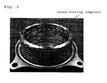
Fig. 3 is a view showing the filter serving as a constitutional element of the inflator according to the present invention after being press-fitted into a base; -
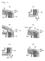
Fig. 4 is a view illustrating a relationship between an inner filter and an inner cover,Figs. 4A and 4B showing a conventional example, whereinFig. 4A shows a case in which an outer peripheral end of an inner filter not having a tapered portion is pressed down such that a height thereof decreases andFig. 4B shows a case in which the inner cover expands upon activation of the inflator such that a gap is formed between the inner cover and an upper end of the inner filter not having a tapered portion, andFigs. 4C to 4F showing an embodiment of the present invention, whereinFig. 4C is a view showing a positional relationship between a lower end of the filter and a base prior to press-fitting into the base,Fig. 4D is similar toFig. 4C but shows a condition following press-fitting into the base,Fig. 4E is a view showing a positional relationship between an upper end of the filter and a diffuser before the diffuser is welded to the base, andFig. 4F is similar toFig. 4E but shows a condition after the diffuser is welded to the base; -
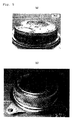
Fig. 5 is a view showing damage to the filter after the inflator has been activated,Fig. 5A showing a case in which a conventional wire wound filter is employed andFig. 5B showing a case in which the filter according to the present invention is employed; -
Fig. 6 is a sectional view illustrating a structure of a dual stage type inflator; -
Fig. 7 is a perspective view illustrating a structure of a wire wound filter that has come into use recently; -
Fig. 8 is a schematic view of a filter test device; -
Fig. 9 is a view showing a deformation curve of a wire wound filter; and -
Fig. 10 is a view showing a wire wound filter following a press-fitting test. -
- 1
- inflator
- 2
- pressure vessel
- 2a
- diffuser
- 2b
- base
- 3
- igniter
- 4
- gas generating agent
- 21
- filter
- 22
- inner filter
- 22b
- tapered portion
- 23
- outer filter
- 24
- inner, cover
- 24a
- bent portion
- In the present invention, the object of ensuring that a wire wound filter can be press-fitted into a base of a pressure vessel easily is realized by covering an outer periphery of an inner filter formed from wound wire with a wire mesh outer filter having a slightly larger outer diameter than an inner diameter of the base.
- An embodiment of the present invention will be described below using
Figs. 1 to 5 .
Fig. 1 is a view of a filter serving as a constitutional element of an inflator according to the present invention from diagonally above. Afilter 21 provided in the inflator of the present invention has a two-layer structure constituted by aninner filter 22 and anouter filter 23. - The
inner filter 22 thereof is a wire wound filter formed by windingmetal wire 22a diagonally into a cylindrical shape and then fixing themetal wire 22a in the cylindrical shape by sintering, for example, in which upper and lower end surfaces of the cylinder are formed in a tapered shape that decreases in height toward an outer peripheral side. The parts formed in a tapered shape will be referred to hereafter as taperedportions 22b. - The
outer filter 23, on the other hand, is not a wire wound filter and is constituted by 18-mesh wire gauze, for example, which is rougher than theinner filter 22. Theouter filter 23 is fitted over an outer peripheral surface of theinner filter 22, excluding the taperedportions 22b on the respective end portions thereof, and has a slightly larger outer diameter than an inner diameter of a base provided on a pressure vessel. - By forming the
filter 21 in this manner, themetal wire 22a of theinner filter 22 does not rise up when thefilter 21 is press-fitted into the base, and therefore thefilter 21 can slide into the base easily, enabling a large reduction in press-fitting pressure. As a result, deformation of thefilter 21 during press-fitting decreases. - By making
metal wire 23a of theouter filter 23 thicker than themetal wire 22a of theinner filter 22 at this time, an improvement in thermal resistance is achieved. As a result, wire breakage on a surface of the filter near a gas discharge hole of a diffuser, which occurs easily when a conventional wire wound filter is employed, can be prevented effectively. - Two of the filters 21 (outer diameter: 64.3 mm) employing two outer filters A, B having following dimensions and constitutions were press-fitted into a base having an inner diameter of 63.72 mm using a test device shown in
Fig. 8 . As shown inFig. 2 , it was found that the pressure applied at a point where thefilter 21 reached a bottom of the base was approximately 329 N. - The internal filter was a wire wound filter formed into a cylindrical shape having an outer diameter of 61.3 mm and a height of 30.25 mm using metal wire having a diameter of 0.36 mm.
The outer filter was wire mesh formed into a cylindrical shape having an outer diameter of 64.3 mm and a height of 26.9 mm using metal wire having a diameter of 0.5 mm. - Hence, where 329 N of pressure was exerted on the
filter 21 using the test device shown inFig. 8 , an inner peripheral portion thereof on an upper side of a paper surface, indicated by a thin arrow inFig. 3 , was completely press-fitted into the base. Note that a direction indicated by a thick arrow inFig. 3 is a pressure application direction. - Incidentally, when a
diffuser 2a is welded to the base and an outer peripheral end of theinner filter 22 contacts thediffuser 2a, theinner filter 22 is pressed down such that the upper end of theinner filter 22 decreases in height from a state indicated by an imaginary line inFig. 4A to a state indicated by a solid line. - When the height of the
inner filter 22 decreases, a gap d is formed between aninner cover 24 and the upper end of theinner filter 22 upon expansion of theinner cover 24 following activation of the inflator, as shown inFig. 4B , and as a result, flaming may occur. - Hence, in the present invention, as shown in
Figs. 4C and 4E , the taperedportion 22b that decreases in height toward the outer peripheral side is formed on the upper and lower end surfaces of theinner filter 22, and a folded backportion 24a of theinner cover 24 is formed to be long enough to remain in contact with an inner wall of theinner filter 22 following activation of the inflator. In this case, the height of theinner filter 22 is preferably set such that the outer peripheral end of theinner filter 22 does not contact the inner wall of thediffuser 2a. - By employing this constitution, when the
filter 21 is press-fitted into abase 2b, the taperedportion 22b on the lower end side of theinner filter 22 contacts an inner wall of thebase 2b in alignment with a shape thereof, as shown inFig. 4D . Further, when thediffuser 2a is welded to thebase 2b, the taperedportion 22b on the upper end side of theinner filter 22 contacts an inner wall of thediffuser 2a in alignment with a shape thereof, as shown inFig. 4F , and therefore the height of theinner filter 22 does not decrease. Hence, even when theinner cover 24 expands upon activation of the inflator, the gap d is not formed between theinner cover 24 and the upper end of theinner filter 22, and as a result, flaming does not occur. -
Fig. 5 shows damage to a conventional wire wound filter and the filter of the present invention following activation of inflators employing the respective filters. As shown inFig. 5A , when a conventional wire wound filter was used, the metal wire near the gas discharge hole of the diffuser was damaged. When the filter of the present invention was used, as shown inFig. 5B , on the other hand, no damage was found on the filter. - The present invention is not limited to the example described above and may be modified appropriately within the scope of the technical spirit set forth in the claims.
- In other words, the airbag inflator described above is merely a preferred example of the present invention, and the present invention may be implemented or executed in other embodiments using various methods. Unless specific limiting description is provided to the contrary in the specification of this application, the present invention is not limited to the component shapes and sizes, constitutional arrangements, and so on illustrated in detail in the attached drawings. Moreover, expressions and terminology used in the specification are employed for descriptive purposes, and unless specific limiting description is provided to the contrary, the present invention is not limited thereto.
- For example, the mesh of the
outer filter 23 is not limited to the example described above. Further, as theinner filter 22 a columnar filter made of expanded metal having various mesh openings may be employed in place of a wire wound filter. - Expanded metal having various mesh openings is wire mesh in which a plurality of mesh opening regions including mesh openings of various sizes, shapes, and pitches are formed on a metal plate (
US 2009/0184504 A1 , for example), and is typically known as variable expanded metal (VEM). When a columnar filter made of expanded metal is used as the inner filter, press-fitting into thebase 2b can be performed more easily than when a wire wound filter is used. Further, the end portions deform appropriately in accordance with the shape of the pressure vessel, and therefore flaming can be suppressed more reliably. Moreover, an improvement in filter performance (trapping of combustion residue and suppression of temperature increases) is achieved in comparison with a case in which a wire wound filter is used as the inner filter. - Furthermore, the inflator is not limited to a dual stage type inflator, and a single stage type inflator may be used. Moreover, in the embodiment, a two-layer structure constituted by the
inner filter 22 and theouter filter 23 is employed, but the respective filters may be provided in multiple layers where appropriate to obtain a layered structure constituted by a total of three or more layers.
Claims (5)
- An airbag inflator in which a pressure vessel formed by integrally welding a diffuser to a base accommodates an igniter and a gas generating agent, a filter disposed along an inner peripheral wall of said pressure vessel, and an inner cover that covers said gas generating agent and includes a bent portion that contacts an inner wall of said filter,
the airbag inflator being characterized in that
said filter has a layered structure constituted by an inner filter in which upper and lower end surfaces of a wire wound filter, wound into a cylindrical shape, are formed in a tapered shape that decreases in height toward an outer peripheral side, and a wire mesh outer filter that is fitted over an outer peripheral surface of said inner filter, excluding at least respective end portions formed in said tapered shape, and has a slightly larger outer diameter than an inner diameter of said base, and
said filter is press-fitted into said base. - The airbag inflator according to claim 1, characterized in that said tapered shape on a lower end side of said filter contacts an inner wall of said base in alignment with a shape thereof when said filter is press-fitted into said base.
- The airbag inflator according to claim 1 or 2, characterized in that a height of said inner filter is set such that an outer peripheral end of said inner filter does not contact an inner wall of said diffuser integrated with said base.
- The airbag inflator according to any of claims 1 to 3, characterized in that said bent portion of said inner cover is formed to be long enough to remain in contact with an inner wall of said inner filter following activation of said inflator.
- The airbag inflator according to any of claims 1 to 4, characterized in that said inner filter is formed from a columnar filter constituted by expanded metal having various mesh openings, in place of said wire wound filter wound into said cylindrical shape.
Applications Claiming Priority (2)
| Application Number | Priority Date | Filing Date | Title |
|---|---|---|---|
| JP2008280348 | 2008-10-30 | ||
| PCT/JP2009/068684 WO2010050588A1 (en) | 2008-10-30 | 2009-10-30 | Airbag inflator |
Publications (3)
| Publication Number | Publication Date |
|---|---|
| EP2340970A1 true EP2340970A1 (en) | 2011-07-06 |
| EP2340970A4 EP2340970A4 (en) | 2012-03-21 |
| EP2340970B1 EP2340970B1 (en) | 2013-10-16 |
Family
ID=42128947
Family Applications (1)
| Application Number | Title | Priority Date | Filing Date |
|---|---|---|---|
| EP09823698.7A Not-in-force EP2340970B1 (en) | 2008-10-30 | 2009-10-30 | Airbag inflator |
Country Status (5)
| Country | Link |
|---|---|
| US (1) | US8328234B2 (en) |
| EP (1) | EP2340970B1 (en) |
| JP (2) | JPWO2010050588A1 (en) |
| CN (2) | CN104773130A (en) |
| WO (1) | WO2010050588A1 (en) |
Families Citing this family (11)
| Publication number | Priority date | Publication date | Assignee | Title |
|---|---|---|---|---|
| DE102008029591B4 (en) * | 2008-06-23 | 2022-03-03 | Zf Airbag Germany Gmbh | Manufacturing process for a gas generator with a multifunctional filter |
| DE202010014286U1 (en) * | 2010-10-15 | 2012-01-30 | Trw Airbag Systems Gmbh | Gas generator and gas bag module |
| JP5638962B2 (en) * | 2011-01-07 | 2014-12-10 | 日本化薬株式会社 | Gas generator |
| JP5784917B2 (en) * | 2011-02-08 | 2015-09-24 | オートリブ ディベロップメント エービー | Inflator for airbag |
| DE102014010942A1 (en) * | 2014-07-28 | 2016-01-28 | Trw Airbag Systems Gmbh | Gas generator for a vehicle occupant safety system, airbag module and vehicle occupant safety system with such a gas generator, and manufacturing method |
| JP7089910B2 (en) * | 2018-03-12 | 2022-06-23 | 株式会社ダイセル | Cylindrical filter for pyrotechnic equipment, manufacturing method of the tubular filter, pyrotechnic equipment using the tubular filter |
| JP6736093B2 (en) * | 2018-03-12 | 2020-08-05 | 富士フィルター工業株式会社 | Filter element and method of manufacturing filter element |
| JP7233855B2 (en) * | 2018-05-22 | 2023-03-07 | 株式会社ダイセル | gas generator |
| JP7181624B2 (en) * | 2020-04-07 | 2022-12-01 | 富士フィルター工業株式会社 | Filter element and method for manufacturing filter element |
| JP7784911B2 (en) * | 2022-02-02 | 2025-12-12 | 日本化薬株式会社 | Wirewound Filter |
| CN115671912A (en) * | 2022-10-12 | 2023-02-03 | 苏州明远汽车零部件制造有限公司 | Automobile airbag gas generator filter device and preparation method |
Family Cites Families (21)
| Publication number | Priority date | Publication date | Assignee | Title |
|---|---|---|---|---|
| JPH0976869A (en) | 1995-09-18 | 1997-03-25 | Nippon Reinz Co Ltd | Filter for inflater and manufacture thereof |
| US5643345A (en) | 1995-09-18 | 1997-07-01 | Morton International, Inc. | Automotive air bag filter with support member |
| JP3925737B2 (en) * | 1996-07-17 | 2007-06-06 | 株式会社神戸製鋼所 | Gas generator for airbag |
| JPH10263336A (en) | 1997-03-26 | 1998-10-06 | Nippon Kayaku Co Ltd | Filter for gas generator |
| JP3935245B2 (en) | 1997-08-12 | 2007-06-20 | ダイセル化学工業株式会社 | Gas generator for airbag and airbag device |
| US6032979C1 (en) | 1998-02-18 | 2001-10-16 | Autoliv Asp Inc | Adaptive output inflator |
| ATE287279T1 (en) * | 1999-02-16 | 2005-02-15 | Daicel Chem | FILTER FOR A MULTI-STAGE GAS GENERATOR FOR AN AIRBAG AND AIRBAG DEVICE |
| JP2001180428A (en) * | 1999-12-27 | 2001-07-03 | Daicel Chem Ind Ltd | Gas generator and airbag device for airbag |
| US6527297B1 (en) * | 2000-08-30 | 2003-03-04 | Autoliv Asp, Inc. | Inflator device ignition of gas generant |
| EP1473202A1 (en) * | 2002-02-06 | 2004-11-03 | Nippon Kayaku Kabushiki Kaisha | Gas generator |
| US6886855B2 (en) | 2002-05-31 | 2005-05-03 | Autoliv Asp, Inc. | Gas generant filter assemblies |
| JP2005067520A (en) * | 2003-08-27 | 2005-03-17 | Nippon Kayaku Co Ltd | Gas generator |
| JP4266344B2 (en) * | 2003-12-19 | 2009-05-20 | ダイセル化学工業株式会社 | Gas generator |
| US7806435B2 (en) * | 2003-12-19 | 2010-10-05 | Daicel Chemical Industries, Ltd. | Gas generator |
| JP4532124B2 (en) * | 2004-01-07 | 2010-08-25 | ダイセル化学工業株式会社 | Airbag gas generator filter |
| JP4370177B2 (en) * | 2004-01-29 | 2009-11-25 | 中央発條株式会社 | Filtration member for inflator and method for producing filtration member for inflator |
| US20060103122A1 (en) * | 2004-11-12 | 2006-05-18 | Trw Vehicle Safety Systems Inc. | Crushed expanded sheet metal filter for an inflator |
| JP4907931B2 (en) * | 2005-09-15 | 2012-04-04 | 日本化薬株式会社 | Gas generator |
| JP4970813B2 (en) * | 2006-03-22 | 2012-07-11 | 株式会社ダイセル | Gas generator for vehicle restraint system |
| US10717032B2 (en) | 2006-09-21 | 2020-07-21 | Acs Industries, Inc. | Expanded metal filters |
| JP4953998B2 (en) * | 2007-09-18 | 2012-06-13 | 株式会社ダイセル | Gas generator for personnel restraint system |
-
2009
- 2009-10-30 CN CN201510130236.1A patent/CN104773130A/en active Pending
- 2009-10-30 WO PCT/JP2009/068684 patent/WO2010050588A1/en not_active Ceased
- 2009-10-30 CN CN2009801430818A patent/CN102202943A/en active Pending
- 2009-10-30 EP EP09823698.7A patent/EP2340970B1/en not_active Not-in-force
- 2009-10-30 US US13/125,739 patent/US8328234B2/en not_active Expired - Fee Related
- 2009-10-30 JP JP2010535852A patent/JPWO2010050588A1/en active Pending
-
2014
- 2014-01-10 JP JP2014003091A patent/JP2014088178A/en active Pending
Also Published As
| Publication number | Publication date |
|---|---|
| US20110254255A1 (en) | 2011-10-20 |
| CN104773130A (en) | 2015-07-15 |
| JP2014088178A (en) | 2014-05-15 |
| JPWO2010050588A1 (en) | 2012-03-29 |
| US8328234B2 (en) | 2012-12-11 |
| EP2340970A4 (en) | 2012-03-21 |
| WO2010050588A1 (en) | 2010-05-06 |
| EP2340970B1 (en) | 2013-10-16 |
| CN102202943A (en) | 2011-09-28 |
Similar Documents
| Publication | Publication Date | Title |
|---|---|---|
| EP2340970B1 (en) | Airbag inflator | |
| EP1837253B1 (en) | Gas generator for occupant restraining device for vehicle | |
| US20070222195A1 (en) | Gas generator for occupant restraining device for vehicle | |
| EP2960118B1 (en) | Gas generator | |
| JP5455932B2 (en) | Gas generator | |
| US8714091B2 (en) | Gas generator | |
| US11458926B2 (en) | Gas generator | |
| CN102414058A (en) | Gas generator | |
| EP2555951B1 (en) | Gas generator and method for assembling same | |
| US20200172044A1 (en) | Gas generator | |
| CN113165595A (en) | Gas generator, airbag module, vehicle safety system and method for producing a gas generator | |
| US7407184B2 (en) | Micro gas generator including an initiator blast shield | |
| JP4266344B2 (en) | Gas generator | |
| JP4819481B2 (en) | Gas generator for airbag | |
| JP6399781B2 (en) | Gas generator | |
| JP2012245873A (en) | Gas generator | |
| JP5545831B2 (en) | Gas generator | |
| EP4267436B1 (en) | Inflator for a passive vehicle safety device | |
| JP2008247302A (en) | Gas generator | |
| JP5795237B2 (en) | Gas generator for personnel restraint system | |
| JP2007008205A (en) | Filter for gas generator and gas generator | |
| CZ20011632A3 (en) | Gas generator |
Legal Events
| Date | Code | Title | Description |
|---|---|---|---|
| PUAI | Public reference made under article 153(3) epc to a published international application that has entered the european phase |
Free format text: ORIGINAL CODE: 0009012 |
|
| 17P | Request for examination filed |
Effective date: 20110323 |
|
| AK | Designated contracting states |
Kind code of ref document: A1 Designated state(s): AT BE BG CH CY CZ DE DK EE ES FI FR GB GR HR HU IE IS IT LI LT LU LV MC MK MT NL NO PL PT RO SE SI SK SM TR |
|
| AX | Request for extension of the european patent |
Extension state: AL BA RS |
|
| RIN1 | Information on inventor provided before grant (corrected) |
Inventor name: NASH, KRISTA Inventor name: CHEN, JIANLIN Inventor name: SAKAMOTO, AKINORI Inventor name: TASAKI, YOJI Inventor name: JENKINS, CASEY |
|
| DAX | Request for extension of the european patent (deleted) | ||
| A4 | Supplementary search report drawn up and despatched |
Effective date: 20120221 |
|
| RIC1 | Information provided on ipc code assigned before grant |
Ipc: B01J 7/00 20060101ALI20120215BHEP Ipc: B60R 21/264 20060101AFI20120215BHEP |
|
| GRAP | Despatch of communication of intention to grant a patent |
Free format text: ORIGINAL CODE: EPIDOSNIGR1 |
|
| INTG | Intention to grant announced |
Effective date: 20130523 |
|
| GRAS | Grant fee paid |
Free format text: ORIGINAL CODE: EPIDOSNIGR3 |
|
| GRAA | (expected) grant |
Free format text: ORIGINAL CODE: 0009210 |
|
| AK | Designated contracting states |
Kind code of ref document: B1 Designated state(s): AT BE BG CH CY CZ DE DK EE ES FI FR GB GR HR HU IE IS IT LI LT LU LV MC MK MT NL NO PL PT RO SE SI SK SM TR |
|
| REG | Reference to a national code |
Ref country code: GB Ref legal event code: FG4D |
|
| REG | Reference to a national code |
Ref country code: CH Ref legal event code: EP |
|
| REG | Reference to a national code |
Ref country code: IE Ref legal event code: FG4D |
|
| REG | Reference to a national code |
Ref country code: AT Ref legal event code: REF Ref document number: 636325 Country of ref document: AT Kind code of ref document: T Effective date: 20131115 |
|
| REG | Reference to a national code |
Ref country code: DE Ref legal event code: R096 Ref document number: 602009019538 Country of ref document: DE Effective date: 20131212 |
|
| REG | Reference to a national code |
Ref country code: NL Ref legal event code: VDEP Effective date: 20131016 |
|
| REG | Reference to a national code |
Ref country code: AT Ref legal event code: MK05 Ref document number: 636325 Country of ref document: AT Kind code of ref document: T Effective date: 20131016 |
|
| REG | Reference to a national code |
Ref country code: LT Ref legal event code: MG4D |
|
| PG25 | Lapsed in a contracting state [announced via postgrant information from national office to epo] |
Ref country code: LT Free format text: LAPSE BECAUSE OF FAILURE TO SUBMIT A TRANSLATION OF THE DESCRIPTION OR TO PAY THE FEE WITHIN THE PRESCRIBED TIME-LIMIT Effective date: 20131016 Ref country code: SE Free format text: LAPSE BECAUSE OF FAILURE TO SUBMIT A TRANSLATION OF THE DESCRIPTION OR TO PAY THE FEE WITHIN THE PRESCRIBED TIME-LIMIT Effective date: 20131016 Ref country code: NL Free format text: LAPSE BECAUSE OF FAILURE TO SUBMIT A TRANSLATION OF THE DESCRIPTION OR TO PAY THE FEE WITHIN THE PRESCRIBED TIME-LIMIT Effective date: 20131016 Ref country code: NO Free format text: LAPSE BECAUSE OF FAILURE TO SUBMIT A TRANSLATION OF THE DESCRIPTION OR TO PAY THE FEE WITHIN THE PRESCRIBED TIME-LIMIT Effective date: 20140116 Ref country code: HR Free format text: LAPSE BECAUSE OF FAILURE TO SUBMIT A TRANSLATION OF THE DESCRIPTION OR TO PAY THE FEE WITHIN THE PRESCRIBED TIME-LIMIT Effective date: 20131016 Ref country code: IS Free format text: LAPSE BECAUSE OF FAILURE TO SUBMIT A TRANSLATION OF THE DESCRIPTION OR TO PAY THE FEE WITHIN THE PRESCRIBED TIME-LIMIT Effective date: 20140216 Ref country code: BE Free format text: LAPSE BECAUSE OF FAILURE TO SUBMIT A TRANSLATION OF THE DESCRIPTION OR TO PAY THE FEE WITHIN THE PRESCRIBED TIME-LIMIT Effective date: 20131016 Ref country code: FI Free format text: LAPSE BECAUSE OF FAILURE TO SUBMIT A TRANSLATION OF THE DESCRIPTION OR TO PAY THE FEE WITHIN THE PRESCRIBED TIME-LIMIT Effective date: 20131016 |
|
| PG25 | Lapsed in a contracting state [announced via postgrant information from national office to epo] |
Ref country code: AT Free format text: LAPSE BECAUSE OF FAILURE TO SUBMIT A TRANSLATION OF THE DESCRIPTION OR TO PAY THE FEE WITHIN THE PRESCRIBED TIME-LIMIT Effective date: 20131016 Ref country code: LV Free format text: LAPSE BECAUSE OF FAILURE TO SUBMIT A TRANSLATION OF THE DESCRIPTION OR TO PAY THE FEE WITHIN THE PRESCRIBED TIME-LIMIT Effective date: 20131016 Ref country code: CY Free format text: LAPSE BECAUSE OF FAILURE TO SUBMIT A TRANSLATION OF THE DESCRIPTION OR TO PAY THE FEE WITHIN THE PRESCRIBED TIME-LIMIT Effective date: 20131016 Ref country code: ES Free format text: LAPSE BECAUSE OF FAILURE TO SUBMIT A TRANSLATION OF THE DESCRIPTION OR TO PAY THE FEE WITHIN THE PRESCRIBED TIME-LIMIT Effective date: 20131016 |
|
| REG | Reference to a national code |
Ref country code: CH Ref legal event code: PL |
|
| PG25 | Lapsed in a contracting state [announced via postgrant information from national office to epo] |
Ref country code: PT Free format text: LAPSE BECAUSE OF FAILURE TO SUBMIT A TRANSLATION OF THE DESCRIPTION OR TO PAY THE FEE WITHIN THE PRESCRIBED TIME-LIMIT Effective date: 20140217 |
|
| REG | Reference to a national code |
Ref country code: DE Ref legal event code: R097 Ref document number: 602009019538 Country of ref document: DE |
|
| REG | Reference to a national code |
Ref country code: IE Ref legal event code: MM4A |
|
| PG25 | Lapsed in a contracting state [announced via postgrant information from national office to epo] |
Ref country code: EE Free format text: LAPSE BECAUSE OF FAILURE TO SUBMIT A TRANSLATION OF THE DESCRIPTION OR TO PAY THE FEE WITHIN THE PRESCRIBED TIME-LIMIT Effective date: 20131016 Ref country code: MC Free format text: LAPSE BECAUSE OF FAILURE TO SUBMIT A TRANSLATION OF THE DESCRIPTION OR TO PAY THE FEE WITHIN THE PRESCRIBED TIME-LIMIT Effective date: 20131016 Ref country code: CH Free format text: LAPSE BECAUSE OF NON-PAYMENT OF DUE FEES Effective date: 20131031 Ref country code: LI Free format text: LAPSE BECAUSE OF NON-PAYMENT OF DUE FEES Effective date: 20131031 |
|
| PLBE | No opposition filed within time limit |
Free format text: ORIGINAL CODE: 0009261 |
|
| STAA | Information on the status of an ep patent application or granted ep patent |
Free format text: STATUS: NO OPPOSITION FILED WITHIN TIME LIMIT |
|
| PG25 | Lapsed in a contracting state [announced via postgrant information from national office to epo] |
Ref country code: CZ Free format text: LAPSE BECAUSE OF FAILURE TO SUBMIT A TRANSLATION OF THE DESCRIPTION OR TO PAY THE FEE WITHIN THE PRESCRIBED TIME-LIMIT Effective date: 20131016 Ref country code: IT Free format text: LAPSE BECAUSE OF FAILURE TO SUBMIT A TRANSLATION OF THE DESCRIPTION OR TO PAY THE FEE WITHIN THE PRESCRIBED TIME-LIMIT Effective date: 20131016 Ref country code: RO Free format text: LAPSE BECAUSE OF FAILURE TO SUBMIT A TRANSLATION OF THE DESCRIPTION OR TO PAY THE FEE WITHIN THE PRESCRIBED TIME-LIMIT Effective date: 20131016 Ref country code: SK Free format text: LAPSE BECAUSE OF FAILURE TO SUBMIT A TRANSLATION OF THE DESCRIPTION OR TO PAY THE FEE WITHIN THE PRESCRIBED TIME-LIMIT Effective date: 20131016 Ref country code: PL Free format text: LAPSE BECAUSE OF FAILURE TO SUBMIT A TRANSLATION OF THE DESCRIPTION OR TO PAY THE FEE WITHIN THE PRESCRIBED TIME-LIMIT Effective date: 20131016 |
|
| 26N | No opposition filed |
Effective date: 20140717 |
|
| GBPC | Gb: european patent ceased through non-payment of renewal fee |
Effective date: 20140116 |
|
| PG25 | Lapsed in a contracting state [announced via postgrant information from national office to epo] |
Ref country code: DK Free format text: LAPSE BECAUSE OF FAILURE TO SUBMIT A TRANSLATION OF THE DESCRIPTION OR TO PAY THE FEE WITHIN THE PRESCRIBED TIME-LIMIT Effective date: 20131016 |
|
| REG | Reference to a national code |
Ref country code: DE Ref legal event code: R097 Ref document number: 602009019538 Country of ref document: DE Effective date: 20140717 |
|
| PG25 | Lapsed in a contracting state [announced via postgrant information from national office to epo] |
Ref country code: IE Free format text: LAPSE BECAUSE OF NON-PAYMENT OF DUE FEES Effective date: 20131030 |
|
| PG25 | Lapsed in a contracting state [announced via postgrant information from national office to epo] |
Ref country code: GB Free format text: LAPSE BECAUSE OF NON-PAYMENT OF DUE FEES Effective date: 20140116 |
|
| PG25 | Lapsed in a contracting state [announced via postgrant information from national office to epo] |
Ref country code: SI Free format text: LAPSE BECAUSE OF FAILURE TO SUBMIT A TRANSLATION OF THE DESCRIPTION OR TO PAY THE FEE WITHIN THE PRESCRIBED TIME-LIMIT Effective date: 20131016 |
|
| PG25 | Lapsed in a contracting state [announced via postgrant information from national office to epo] |
Ref country code: SM Free format text: LAPSE BECAUSE OF FAILURE TO SUBMIT A TRANSLATION OF THE DESCRIPTION OR TO PAY THE FEE WITHIN THE PRESCRIBED TIME-LIMIT Effective date: 20131016 |
|
| PG25 | Lapsed in a contracting state [announced via postgrant information from national office to epo] |
Ref country code: TR Free format text: LAPSE BECAUSE OF FAILURE TO SUBMIT A TRANSLATION OF THE DESCRIPTION OR TO PAY THE FEE WITHIN THE PRESCRIBED TIME-LIMIT Effective date: 20131016 |
|
| PG25 | Lapsed in a contracting state [announced via postgrant information from national office to epo] |
Ref country code: MK Free format text: LAPSE BECAUSE OF FAILURE TO SUBMIT A TRANSLATION OF THE DESCRIPTION OR TO PAY THE FEE WITHIN THE PRESCRIBED TIME-LIMIT Effective date: 20131016 Ref country code: LU Free format text: LAPSE BECAUSE OF NON-PAYMENT OF DUE FEES Effective date: 20131030 Ref country code: HU Free format text: LAPSE BECAUSE OF FAILURE TO SUBMIT A TRANSLATION OF THE DESCRIPTION OR TO PAY THE FEE WITHIN THE PRESCRIBED TIME-LIMIT; INVALID AB INITIO Effective date: 20091030 Ref country code: BG Free format text: LAPSE BECAUSE OF FAILURE TO SUBMIT A TRANSLATION OF THE DESCRIPTION OR TO PAY THE FEE WITHIN THE PRESCRIBED TIME-LIMIT Effective date: 20131016 |
|
| PG25 | Lapsed in a contracting state [announced via postgrant information from national office to epo] |
Ref country code: MT Free format text: LAPSE BECAUSE OF FAILURE TO SUBMIT A TRANSLATION OF THE DESCRIPTION OR TO PAY THE FEE WITHIN THE PRESCRIBED TIME-LIMIT Effective date: 20131016 Ref country code: GR Free format text: LAPSE BECAUSE OF NON-PAYMENT OF DUE FEES Effective date: 20131016 |
|
| REG | Reference to a national code |
Ref country code: FR Ref legal event code: PLFP Year of fee payment: 7 |
|
| PGFP | Annual fee paid to national office [announced via postgrant information from national office to epo] |
Ref country code: DE Payment date: 20151023 Year of fee payment: 7 |
|
| PGFP | Annual fee paid to national office [announced via postgrant information from national office to epo] |
Ref country code: FR Payment date: 20151027 Year of fee payment: 7 |
|
| PG25 | Lapsed in a contracting state [announced via postgrant information from national office to epo] |
Ref country code: GR Free format text: LAPSE BECAUSE OF FAILURE TO SUBMIT A TRANSLATION OF THE DESCRIPTION OR TO PAY THE FEE WITHIN THE PRESCRIBED TIME-LIMIT Effective date: 20140117 |
|
| REG | Reference to a national code |
Ref country code: DE Ref legal event code: R119 Ref document number: 602009019538 Country of ref document: DE |
|
| REG | Reference to a national code |
Ref country code: FR Ref legal event code: ST Effective date: 20170630 |
|
| PG25 | Lapsed in a contracting state [announced via postgrant information from national office to epo] |
Ref country code: DE Free format text: LAPSE BECAUSE OF NON-PAYMENT OF DUE FEES Effective date: 20170503 Ref country code: FR Free format text: LAPSE BECAUSE OF NON-PAYMENT OF DUE FEES Effective date: 20161102 |