EP2340795A1 - Applicator for tampon - Google Patents
Applicator for tampon Download PDFInfo
- Publication number
- EP2340795A1 EP2340795A1 EP09810046A EP09810046A EP2340795A1 EP 2340795 A1 EP2340795 A1 EP 2340795A1 EP 09810046 A EP09810046 A EP 09810046A EP 09810046 A EP09810046 A EP 09810046A EP 2340795 A1 EP2340795 A1 EP 2340795A1
- Authority
- EP
- European Patent Office
- Prior art keywords
- tampon applicator
- outer tube
- diameter section
- tampon
- present
- Prior art date
- Legal status (The legal status is an assumption and is not a legal conclusion. Google has not performed a legal analysis and makes no representation as to the accuracy of the status listed.)
- Granted
Links
Images










Classifications
-
- A—HUMAN NECESSITIES
- A61—MEDICAL OR VETERINARY SCIENCE; HYGIENE
- A61F—FILTERS IMPLANTABLE INTO BLOOD VESSELS; PROSTHESES; DEVICES PROVIDING PATENCY TO, OR PREVENTING COLLAPSING OF, TUBULAR STRUCTURES OF THE BODY, e.g. STENTS; ORTHOPAEDIC, NURSING OR CONTRACEPTIVE DEVICES; FOMENTATION; TREATMENT OR PROTECTION OF EYES OR EARS; BANDAGES, DRESSINGS OR ABSORBENT PADS; FIRST-AID KITS
- A61F13/00—Bandages or dressings; Absorbent pads
- A61F13/15—Absorbent pads, e.g. sanitary towels, swabs or tampons for external or internal application to the body; Supporting or fastening means therefor; Tampon applicators
- A61F13/20—Tampons, e.g. catamenial tampons; Accessories therefor
- A61F13/26—Means for inserting tampons, i.e. applicators
Definitions
- FIG. 1 A configuration of a tampon applicator according to a first embodiment of the present invention will be described with reference to Fig. 1 to Fig. 3 .
- the menstrual blood having been adhered to a surface of an outer tube 103 in vaginal cavity is adapted to adhere to a side face of a convex portion 110, thus making it possible to avoid a circumstance that when the tampon applicator 101 is pulled out from the inside of vaginal cavity, a user's fingers are contaminated by the menstrual blood running down along a surface of the outer tube 103.
- a tampon applicator 101 according to Exemplary Modification 3 of the present invention will be described.
- the tampon applicator 101 according to this Exemplary Modification 3 will be described focusing on the tampon applicator 101 according to the second embodiment of the present invention.
- a depth of the valley-shaped portion that is curved to the rear end side of the outer tube 1003 may be formed to be greater than that of the mountain-shaped portion Y that is curved to the front end side of the outer tube 1003.
- Japanese Patent Application No. 2008-222478 (filed on August 29, 2008 ), Japanese Patent Application No. 2008-222575 (filed on August 29, 2008 ), and Japanese Patent Application No. 2008-222472 (filed on August 29, 2008 ) are incorporated into the specification of the present application by reference.
- a tampon applicator can be provided which is capable of enhancing an effect of cleanly wiping menstrual blood adhering to a surface of an outer tube without a need to employ an absorptive sheet for covering the outer tube.
- the present invention is thus advantageous in a tampon applicator.
Landscapes
- Health & Medical Sciences (AREA)
- Epidemiology (AREA)
- Engineering & Computer Science (AREA)
- Biomedical Technology (AREA)
- Heart & Thoracic Surgery (AREA)
- Vascular Medicine (AREA)
- Life Sciences & Earth Sciences (AREA)
- Animal Behavior & Ethology (AREA)
- General Health & Medical Sciences (AREA)
- Public Health (AREA)
- Veterinary Medicine (AREA)
- Absorbent Articles And Supports Therefor (AREA)
Abstract
Description
- The present invention relates to a tampon applicator which includes an outer tube and a push-out portion, the outer tube having: a large-diameter section for storing a tampon; and a small-diameter section which is smaller in diameter than the large-diameter section that is positioned at a base portion side more than the large-diameter section, the push-out portion being adapted to press the tampon that is stored in the large-diameter section from a backward side to be able to be pushed out from an opening portion of a front end of the outer tube.
- Conventionally, there is known a tampon applicator of which outer tube is covered with an absorptive sheet which is capable of absorbing and retaining menstrual blood in order to disallow a circumstance that a user's hands are contaminated by the menstrual blood adhering to a surface of such tampon applicator when the user has pulled out the tampon applicator from her vaginal cavity (refer to Patent Document 1).
-
- [Patent Document 1]
Japanese Patent No.3998462 - [Patent Document 2]
Japanese Patent No.3489833 - However, the abovementioned tampon applicator is constituted so that an outer tube thereof is covered with the abovementioned absorptive sheet; and therefore, manufacturing cost increases with an increased number of members, there is a danger that part of such absorptive sheet remains in virginal cavity, and there has been a problem that an outer diameter of the outer tube increases.
- Therefore, the present invention has been made in view of the above-described problem, and it is an object of the present invention to provide a tampon applicator which is capable of enhancing an effect of cleanly wiping menstrual blood adhering to a surface of an outer tube without need to employ an absorptive sheet for covering the outer tube.
- The first feature of the present invention is summarized in that a tampon applicator including an outer tube having: a large-diameter section for storing a tampon; and a small-diameter section which is smaller in diameter than the large-diameter section that is positioned at a base portion side more than the large-diameter section; and a push-out member which is inserted slidably into an opening portion at a rear end of the outer tube and is capable of compressing from rear the tampon that is stored in the large-diameter section and then pushing out the compressed tampon from an opening portion at a front end of the outer tube, wherein at least one opening is provided on an exterior face of the large-diameter section.
- The second feature of the present invention is summarized in that a tampon applicator including: an outer tube having: a large-diameter section for storing a tampon; and a small-diameter section which is smaller in diameter than the large-diameter section that is positioned at a base portion side more than the large-diameter section; and a push-out member which is inserted slidably into an opening portion at a rear end of the outer tube and is capable of compressing from rear the tampon that is stored in the large-diameter section and then pushing out the compressed tampon from an opening portion at a front end of the outer tube, wherein a plurality of convex portions are provided on an exterior face of the large-diameter section.
- The third feature of the present invention is summarized in that a tampon applicator including: an outer tube having: a large-diameter section for storing a tampon; and a small-diameter section which is smaller in diameter than the large-diameter section that is positioned at a base portion side more than the large-diameter section; and a push-out member which is inserted slidably into an opening portion at a rear end of the outer tube and is capable of compressing from rear the tampon that is stored in the large-diameter section and then pushing out the compressed tampon from an opening portion at a front end of the outer tube, wherein a plurality of concave portions are provided on an exterior face of the large-diameter section, the large-diameter section is equally divided into three portions, a forward portion, a central portion, and a backward portion, the number of concave portions which are provided at the backward portion s constituted so as to be greater than that of concave portions which are provided at the forward portion and the central portion.
- As has been described above, according to the present invention, a tampon applicator can be provided which is capable of enhancing an effect of cleanly wiping menstrual blood adhering to a surface of an outer tube without a need to employ an absorptive sheet for covering the outer tube.
-
- [
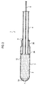
Fig. 1] Fig. 1 is a perspective view of a tampon applicator according to a first embodiment of the present invention. - [
Fig. 2] Fig. 2 is a sectional view taken along the line A-A' of the tampon applicator according to the first embodiment of the present invention. - [
Fig. 3] Fig. 3 is an enlarged view of a large-diameter section in the sectional view taken along the line A-A' of the tampon applicator according to the first embodiment of the present invention. - [
Fig. 4] Fig. 4 is a side view of a tampon applicator according toExemplary Modification 1 of the present invention. - [
Fig. 5] Fig. 5 is an enlarged view of a large-diameter section in the sectional view taken along the line A-A' of a tampon applicator according to Exemplary Modification 2 of the present invention. - [
Fig. 6] Fig. 6 is a side view of a tampon applicator according toExemplary Modification 3. - [
Fig. 7] Fig. 7 is a perspective view of a tampon applicator according to a second embodiment of the present invention. - [
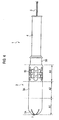
Fig. 8] Fig. 8 is a sectional view taken along theline 100A-100A' of the tampon applicator according to the second embodiment of the present invention. - [
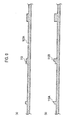
Fig. 9] Fig. 9 is a sectional view taken along theline 100A-A' of the tampon applicator according to the second embodiment of the present invention. - [
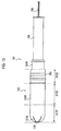
Fig. 10] Fig. 10 is a side view of the tampon applicator according toExemplary Modification 1 of the present invention. - [
Fig. 11] Fig. 11 is a side view of the tampon applicator according to Exemplary Modification 2 of the present invention. - [
Fig. 12] Fig. 12 is an enlarged view of a large-diameter section in the sectional view taken along theline 100A-100A' of the tampon applicator according toExemplary Modification 3 of the present invention. - [
Fig. 13] Fig. 13 is an enlarged view of the large-diameter section in the sectional view taken along theline 100A-100A' of the tampon applicator according toExemplary Modification 3 of the present invention. - [
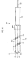
Fig. 14] Fig. 14 is a side view of a tampon applicator according to Exemplary Modification 4 of the present invention. - [
Fig. 15] Fig. 15 is a perspective view of a tampon applicator according to a third embodiment of the present invention. - [
Fig. 16] Fig. 16 is a sectional view taken along theline 1000A-1000A' of the tampon applicator according to the third embodiment of the present invention. - [
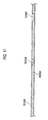
Fig. 17] Fig. 17 is an enlarged view of a large-diameter section in the sectional view taken along theline 1000A-1000A' of the tampon applicator according to the third embodiment of the present invention. - [
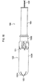
Fig. 18] Fig. 18 is a side view of the tampon applicator according toExemplary Modification 1 of the present invention. - [
Fig. 19] Fig. 19 is a side view of the tampon applicator according to Exemplary Modification 2 of the present invention. - [
Fig. 20] Fig. 20 is a side view of the tampon applicator according toExemplary Modification 3 of the present invention. - [
Fig. 21] Fig. 21 is a side view of the tampon applicator according to Exemplary Modification 4 of the present invention. - A configuration of a tampon applicator according to a first embodiment of the present invention will be described with reference to
Fig. 1 to Fig. 3 . -
Fig. 1 is a perspective view of atampon applicator 1 according to the embodiment;Fig. 2 is a sectional view taken along the line A-A' of thetampon applicator 1 according to the embodiment; andFig. 3 (a) and Fig. 3 (b) are enlarged views of a large-diameter section 3A of anouter tube 3 in the sectional view taken along the line A-A' of thetampon applicator 1 according to the embodiment. - As shown in
Fig. 1 andFig. 2 , thetampon applicator 1 according to the embodiment has anouter tube 3 and a push-out member 4. - The
outer tube 3, a transverse cross section of which is formed in a substantially circular shape, has: a large-diameter section 3A for stored a tampon 2; and a small-diameter section 3B which is smaller in diameter than the large-diameter section 3A that is positioned at a base portion side more than the large-diameter section 3A. - At a front end of the
outer tube 3, anopening portion 7 is formed by means of a radial slit. At theopening portion 7, a plurality ofpiece portions 7A is formed by means of such slit. - The push-out member 4 is slidably inserted into an opening portion 6 at a rear end of the
outer tube 3 and is constituted to compress the tampon 2 stored in the large-diameter section 3A from a backward side so as to be thereby able to push out the compressed tampon from theopening portion 7 at the front end of theouter tube 3. - As shown in
Fig. 2 , in the tampon 2, a pullout cord 5 extends from a rear end of the tampon and such pullout cord 5 extends to the outside of thetampon applicator 1 through the inside of the push-out member 4. - In addition, the tampon 2 that is stored in the
outer tube 3 is constituted to be pushed from a backward side by means of the push-out member 4 when it is inserted into virginal cavity and to push and widen thepiece portions 7A that are formed at theopening portion 7 so as to be exposed to the outside of theouter tube 3. - In addition, at least one
opening 10 is provided on an exterior face of the large-diameter section 3A. For example, as shown inFig. 3 (a) and Fig. 3 (b) , theopening 10 that is provided on the exterior face of the large-diameter section 3A may be a plurality of through holes. - In an example of
Fig. 3 (a) , it is preferable that a diameter of the opening (through hole) 10 is 6 mm or less and that a thickness of the large-diameter section 3A is 1 mm or less. - In addition, in the example of
Fig. 3 (a) , it is preferable that intervals between the openings (through holes) 10 is 2 mm or more. Here, in a case where the intervals between the openings (through holes) 10 is 2 mm or more, it has a strength which is durable for a pressure at the time of transportation or use, and in a case where the intervals between the openings (through holes) 10 are 5 mm or more, it is stronger and it can impart a sense of easiness on appearance without exposing the tampon 2. - In addition, as shown in
Fig. 3 (b) , in a specific opening (throughhole 10A, a side face 10A1 at a front end side of theouter tube 3 may be adapted to tilt by a predetermined angle (for example, 30 degrees) in an insertion direction D1 of thetampon applicator 1. - In addition, in a specific opening (through hole) 10B, a side face 10B2 at a rear end side of the
outer tube 3 may be adapted to tilt by a predetermined angle (for example, 30 degrees) in a pullout direction D2 of thetampon applicator 1. - Further, in a specific opening (through hole) 10C, a side face 10C1 at the front end side of the
outer tube 3 may be adapted to tilt by a predetermined angle (for example, 30 degrees) in the insertion direction D1 of thetampon applicator 1 and a side face 10C2 at the rear end side of theouter tube 3 may be adapted to tilt by a predetermined angle (for example, 30 degrees) in the pullout direction of thetampon applicator 1. - Moreover, it is preferable that the
outer tube 3 is formed of a material of which surface energy is less than 37 × 10-3 N/m. The material of which surface energy is less than 37 × 10-3 N/m is assumed to include a material such as paper, rubber, or nylon which is surface-coated with the material of which surface energy is less than 37 × 10-3 N/m. - For example, the
outer tube 3 is formed of: polyethylene of which surface energy is less than 31 × 10-3 N/m; polypropylene of which surface energy is less than 29 × 10-3 N/m; a silicon resin of which surface energy is less than 20 × 10-3 N/m; or polytetra fluoroethylene of which surface energy is less than 18.5 × 10⁻³ N/m or the like. - In a case where the
outer tube 3 is formed of a material of which surface energy is 37 × 10-3 N/m or more (such as polyvinyl alcohol of which surface energy is 37 × 10-3 N/m or more, for example), the menstrual blood adhering to a surface of theouter tube 3 is absorbed into a material forming theouter tube 3; and therefore, use of the outer tube formed of such material is not preferable. - Here, surface energy can be analyzed by means of full automatic contact angle gauge DM700 which is available from Kyowa Interface Science Co., Ltd.
- According to the
tampon applicator 1 according to the first embodiment of the present invention, the applicator is constituted so that the menstrual blood having been adhered to thesurface cylinder 3 in vaginal cavity is guided into athrough hole 10, thus making it possible to avoid a circumstance that when thetampon applicator 1 is pulled out from the inside of vaginal cavity, a user's fingers are contaminated by the menstrual blood dropping along the surface of theouter tube 3. - In addition, with the
tampon applicator 1 according to the first embodiment of the present invention, throughholes 10 are provided all over an external face of theouter tube 3, thus making it possible to entirely reduce the menstrual blood dripping along the surface of theouter tube 3 when thetampon applicator 1 is pulled out from the inside of vaginal cavity. - In addition, with the
tampon applicator 1 according to the first embodiment of the present invention, the applicator is constituted so that the menstrual blood that remains in the vaginal cavity when thetampon applicator 1 is inserted into vaginal cavity is guided and adheres to the throughhole 10, thus making it possible to avoid initial use leakage from the tampon 2. - In particular, with the
tampon applicator 1 according to the first embodiment of the present invention, since side faces of the throughholes 10A to 10C tilt, when thetampon applicator 1 is inserted into vaginal cavity, the menstrual blood that remains in vaginal cavity can be guided to the throughhole 10 more effectively. - Further, with the
tampon applicator 1 according to the first embodiment of the present invention, even in a case where the surface of theouter tube 3 is wiped out by tissue paper or the like, menstrual blood still remains with the blood adhering to a side face of a throughhole 10; and therefore, it is possible to readily discriminate whether or not thetampon applicator 1 has already been used. - Referring to
Fig. 4 , atampon applicator 1 according toExemplary Modification 1 of the present invention will be described. Hereinafter, thetampon applicator 1 according to thisExemplary Modification 1 will be described focusing on differences from thetampon applicator 1 according to the first embodiment of the present invention. - In the
tampon applicator 1 according to thisExemplary Modification 1, in a case where a large-diameter section 3A is equally divided into three portions, a forward portion A1, a central portion A2, and a backward portion A3, the number ofopenings 10 which are provided at the backward portion A3 is adapted to be more than that ofopenings 10 which are provided at the forward portion A1 and the central portion A2. - For example, as shown in
Fig. 4 , the abovementioned openings (for example, through holes) 10 may be provided at the backward portion A3 only. Such openings (for example, through holes) 10 may be provided at least at the backward portion A3, and it is preferable that the number ofopenings 10 which are provided at the backward portion A3 is more than that ofopenings 10 which are provided at the forward portion A1 and the central portion A2. With thetampon applicator 1 according to thisExemplary Modification 1, since thetampon applicator 1 is pulled out from the inside of vaginal cavity with the backward portion A3 down, the menstrual blood adhering to thetampon applicator 1 is likely to drip along the backward portion A3; and however, in a case where there are openings (through holes) 10 at the forward portion A1 or the central portion A2, there is a possibility that a hand or a cloth is contaminated due to running down of the menstrual blood adhering to the backward portion A3 side more than the openings (through holes) 10. Therefore, the menstrual blood that is running down can be reduced in a case of providingmore openings 10 at the backward portion A3 more remarkably than in a case wheremore openings 10 are provided at the forward portion A1 and the central portion A2. - Referring to
Fig. 5 , atampon applicator 1 according to Exemplary Modification 2 of the present invention will be described. Hereinafter, thetampon applicator 1 according to this Exemplary Modification 2 will be described focusing differences from thetampon applicator 1 according to the first embodiment of the present invention. - In the
tampon applicator 1 according to Exemplary Modification 2 of the present invention, as shown inFig. 5 , anopening 11 which is provided on an exterior face of a large-diameter section 3A is formed by a hole having a predetermined depth instead of being formed by a through hole. - Referring to
Fig. 6 , atampon applicator 1 according toExemplary Modification 3 of the present invention will be described. Hereinafter, thetampon applicator 1 according to thisExemplary Modification 3 will be described focusing to differences from thetampon applicator 1 according to the first embodiment of the present invention. - In the
tampon applicator 1 according to Exemplary Modification 2 of the present invention, anopening 11 which is provided on an exterior face of a large-diameter section 3A is formed in a noncircular shape. For example, as shown inFig. 6 , theabovementioned opening 12 may be formed in a shape which is curved to a rear end side of the outer tube 3 (in a crescent shape). In addition, theabovementioned opening 12 may be formed in a heart shape or in a character shape or the like. - Referring to
Fig. 7 to Fig. 9 , a configuration of a tampon applicator according to a second embodiment of the present invention will be described. -
Fig. 7 is a perspective view of atampon applicator 101 according to the embodiment;Fig. 8 is a sectional view taken along theline 100A-100A' of thetampon applicator 101 according to the embodiment; andFig. 9 (a) and Fig. 9 (b) are enlarged views of a large-diameter section 103A of anouter tube 103 in the sectional view taken along theline 100A-100A' of thetampon applicator 101 according to the embodiment. - As shown in
Fig. 7 andFig. 8 , thetampon applicator 101 according to the embodiment has anouter tube 103 and a push-outmember 104. - The
outer tube 103, a transverse cross section of which is formed in a substantially circular shape, has: a large-diameter section 103A for storing atampon 102; and a small-diameter section 103B of a smaller diameter than that of the large-diameter section 103A that is positioned at a base portion side more than the large-diameter section 103A. - At a front end of the
outer tube 103, anopening portion 107 is formed by means of a radial slit. Atsuch opening portion 107, a plurality ofpiece portions 107A is formed by means of such slit. - The push-out
member 104 is inserted slidably into theopening portion 106 at a rear end of theouter tube 103 and is constituted to compress thetampon 102 that is stored in the large-diameter section 103A to be able to push out the compressed tampon from theopening diameter portion 107 at a front end of theouter tube 103. - As shown in
Fig. 8 , in thetampon 102, apullout cord 105 extends from a rear end of the tampon, andsuch pullout cord 105 extends to the outside of thetampon applicator 101 through the inside of the push-outmember 104. - In addition, the
tampon 102 that is stored in theouter tube 103 is pushed from a backward side by means of the push-outmember 104 when it is inserted into vaginal cavity to push and widen thepiece portions 107A that are formed at theopening portion 107 so as to be exposed to the outside of theouter tube 103. - In addition, a plurality of
convex portions 110 are provided on an exterior face of the large-diameter section 103A. As shown inFig. 7 , at least one of theconvex portions 110 is formed in a continuous shape and is formed so as to go around the large-diameter section 103A. - For example, as shown in
Fig. 7 , a plurality of convex portions (convex grooves) 110 that are formed in the continuous shape and are formed so as to go around the large-diameter section 103A may be provided in parallel to each other. Suchconvex portions 110 may be constituted so as to go around in a cross section which is vertically cut in a longitudinal direction of thetampon applicator 101 or may be constituted so as to go around in the other cross section. - In addition, a plurality of
convex portions 110 may be formed along an outer circumference of the large-diameter section 103A. In addition, theconvex portions 110 may be formed in a continuous shape and may be formed in part of the large-diameter section 103A. - In an example of
Fig. 9 (a) , it is preferable that a height of theconvex portion 110 is 0.1 mm or more and 3 mm or less. Here, in a case where the height of theconvex portion 110 is 3 mm or less, a rugged sense of feeling on appearance or a sense of discomfort at the time of use can be avoided. Further, in a case where the height of theconvex portion 110 is 1.5 mm or less, even if theconvex portion 110 touches a user's skin, the user does not have a feeling of discomfort such as a pain and can insert thetampon applicator 101 into her vaginal cavity. If the height of theconvex portion 110 is 0.1 mm or more, an effect of wiping out the menstrual blood adhering to a surface of theouter tube 103 cannot be obtained. - In the example of
Fig. 9 (a) , it is preferable that intervals between theconvex portions 110 are 1 mm or more. Here, if the intervals between theconvex portions 110 are less than 1 mm, there is a possibility that, when theouter tube 103 is removed from a die, theconvex portion 110 breaks or has a chip. In addition, if the intervals between theconvex portions 110 are too narrow, since the capacitance of the menstrual blood entering between theconvex portion 110 and theconvex portion 110 lessens and the menstrual blood overflows without adhering to a side face of theconvex portion 110, it is preferable that the intervals between theconvex portions 110 are 5 mm or more. - In addition, widths of the plurality of
convex portions 110 may be identical to or may be different from each other. It is preferable that the intervals of theconvex portions 110 each are 0.1 mm or more and 8 mm or less. Here, in a case where the widths of theconvex portions 110 each are less than 0.1 mm, there is a possibility that a user feels a pain or damages the inside of vaginal cavity at the time of using thetampon applicator 101 and there is a possibility that when theouter tube 103 is removed from a die, theconvex portion 110 breaks or has a chip. - On the other hand, if the widths of the
convex portions 110 each are 0.4 mm or more and 3 mm or less, a user can use thetampon applicator 101 without any pain and a manufacturer can stably manufacture thetampon applicator 101. If the widths of theconvex portions 110 each are greater than 8 mm, an effect of wiping out the menstrual blood adhering to the surface of theouter tube 103 cannot be obtained. - Further, in a specific
convex portion 110, at least either one of a side face at a front end side of theouter tube 103 and a side face at a rear end side of theouter tube 103 may be constituted so as to tilt by a predetermined angle in an insertion direction of thetampon applicator 101 or in a pullout direction of thetampon applicator 101. - Moreover, in at least one of the
convex portions 110, a height of a rear end side of theouter tube 103 may be formed so as to be greater than that of a front end side of theouter tube 103. - For example, as shown in
Fig. 9 (b) , a top face of theconvex portion 110A may tilt so that the height of the rear end side of theouter tube 103 is greater than that of the front end side of theouter tube 103 or a step difference may be provided on the top face of theconvex portion 110A. - In addition, it is preferable that the
outer tube 103 is formed of a material of which surface energy is less than 37 × 10-3 N/m. The material of which surface energy is less than 37 × 10-3 N/m is assumed to include a material such as paper, rubber, or nylon which is surface-coated with the material of which surface energy is less than 37 × 10-3 N/m. - For example, the
outer tube 103 is formed of: polyethylene of which surface energy is less than 31 × 10-3 N/m; polypropylene of which surface energy is less than 29 × 10-3 N/m; a silicone resin of which surface energy is less than 20 × 10-3 N/m; or polytetra fluoroethylene of which surface energy is less than 18.5 × 10⁻³ N/m or the like. - In a case where the
outer tube 103 is formed of a material of which surface energy is 37 × 10-3 N/m or more (such as polyvinyl alcohol of which surface energy is 37 × 10-3 N/m or more, for example), the menstrual blood adhering to a surface of theouter tube 103 is absorbed into a material forming theouter tube 103; and therefore, use of the outer tube formed of such material is not preferable. - Here, surface energy can be analyzed by means of full automatic contact angle gauge DM700 which is available from Kyowa Interface Science Co., Ltd.
- With a
tampon applicator 101 according to the second embodiment, the menstrual blood having been adhered to a surface of anouter tube 103 in vaginal cavity is adapted to adhere to a side face of aconvex portion 110, thus making it possible to avoid a circumstance that when thetampon applicator 101 is pulled out from the inside of vaginal cavity, a user's fingers are contaminated by the menstrual blood running down along a surface of theouter tube 103. - In addition, with the
tampon applicator 101 according to the second embodiment of the present invention, since aconvex portion 110 which is formed in a continuous shape so as to go around an exterior face of theouter tube 103 is provided, the menstrual blood running down along the surface of theouter tube 103 when thetampon applicator 101 is pulled out from the inside of vaginal cavity can be prevented. - In addition, with the
tampon applicator 101 according to the second embodiment of the present invention, since the side faces of theconvex portions 110A to 110C tilt, the menstrual blood that remains in vaginal cavity when thetampon applicator 101 is inserted into vaginal cavity can be adhered to the side faces of theconvex portions 110A to 110C more effectively. - Further, with the
tampon applicator 101 according to the second embodiment of the present invention, even in a case where the surface of theouter tube 103 has been wiped out by means of tissue paper or the like, since the menstrual blood remains with it adhering to the side face of theconvex portion 110, it is possible to readily discriminate whether or not thetampon applicator 101 is the one that has already been used. - Referring to
Fig. 10 , atampon applicator 101 according toExemplary Modification 1 of the present invention will be described. Hereinafter, thetampon applicator 101 according to thisExemplary Modification 1 will be described focusing on differences from thetampon applicator 101 according to the second embodiment of the present invention. - In the
tampon applicator 101 according to thisExemplary Modification 1, in a case where a large-diameter section 103A is equally divided into three sections, a forward portion A101, a central portion A102, and a backward portion A103, the applicator is constituted so that the number ofconvex portions 110 which are provided at the backward portion A103 is more than that ofconvex portions 110 which are provided at the forward portion A101 and the central portion A102. - For example, as shown in
Fig. 10 , the abovementionedconvex portions 110 may be provided at the backward portion A103 only. Theconvex potions 110 may be provided at least at the backward portion A103, and the number ofconvex portions 110 which are provided at the backward portion A103 may be greater than that ofconvex portions 110 which are provided at the forward portion A101 and the central portion A102. With thetampon applicator 101 according toExemplary Modification 1, since thetampon applicator 101 is pulled out from the inside of vaginal cavity with the backward portion A103 side down, the menstrual blood adhering to thetampon applicator 101 is likely to run along the backward portion A103; and however, in a case where aconvex portion 110 is present at the forward portion A101 or the central portion A102, there is a possibility that a hand or a cloth is contaminated due to running down of the menstrual blood adhering to the backward portion A103 side more than theconvex portion 110. Therefore, the menstrual blood that is running down can be reduced in a case of providing moreconvex portions 110 at the backward portion A103 more remarkably than in a case where moreconvex portions 110 are provided at the forward portion A101 and the central portion A102. - Referring to
Fig. 11 , atampon applicator 101 according to Exemplary Modification 2 of the present invention will be described. Hereinafter, thetampon applicator 101 according to Exemplary Modification 2 will be described focusing on differences from thetampon applicator 101 according to the second embodiment of the present invention. - As shown in
Fig. 11 , in thetampon applicator 101 according to this Exemplary Modification 2, at least one ofconvex portions 111 which are provided on an outer face of anouter tube 103 is formed in a continuous, substantially wave-like shape and is formed so as to go around a large-diameter section 103A. - Referring to
Fig. 12 andFig. 13 , atampon applicator 101 according toExemplary Modification 3 of the present invention will be described. Hereinafter, thetampon applicator 101 according to thisExemplary Modification 3 will be described focusing on thetampon applicator 101 according to the second embodiment of the present invention. - Here, in the
tampon applicator 101 according to thisExemplary Modification 3, a height of a convex portion which is provided at the rearmost end side of anouter tube 103 is formed so as to be the greatest among a plurality of convex portions. - For example, as shown in
Fig. 12 , a height of aconvex portion 112C which is provided at the rear end side of theouter tube 103 which is provided at the most outer part is formed so as to be the greatest among a plurality ofconvex potions 112A to 112C. Here, a height of theconvex portion 112A may be smaller than that of aconvex portion 112B which is provided at a rear end side of theouter tube 103 more than theconvex portion 112A. - In addition, as shown in
Fig. 13 , the height of theconvex portion 113C that is provided at the most rear end side of theouter tube 103 is formed so as to be the greatest among the plurality ofconvex potions 113A to 113C. Here, the heights of theconvex portions convex portion 113C may be identical to each other. - Referring to
Fig. 14 , atampon applicator 101 according to Exemplary Modification 4 of the present invention will be described. Hereinafter, thetampon applicator 101 according to this Exemplary Modification 4 will be described focusing on differences from thetampon applicator 101 according to the second embodiment of the present invention. - Here, in the
tampon applicator 101 according to this Exemplary Modification 4, at least one ofconvex portions 114 which are provided at anouter tube 103 is formed in an intermittent shape and is formed so as to go around a large-diameter section 103A. - Specifically, as shown in
Fig. 14 , in thetampon applicator 101 according to this Exemplary Modification 4, in a case where imaginary lines V1 to V3 are drawn along a longitudinal direction, the imaginary lines V1 to V3 are adapted to always cross theconvex potions 114 that are formed so as to go around the large-diameter section 103A in an intermittent shape. - Referring to
Fig. 15 to Fig. 17 , a configuration of a tampon applicator according to a third embodiment of the present invention will be described. -
Fig. 15 is a perspective view of atampon applicator 1001 according to the embodiment;Fig. 16 is a sectional view taken along theline 1000A-1000A' of thetampon applicator 1001 according to the embodiment; andFig. 17 is an enlarged view of a large-diameter section 1003A of anouter tube 1003 in the sectional view taken along theline 1 000A-1 000A' of thetampon applicator 1001 according to the embodiment. - As shown in
Fig. 15 andFig. 16 , thetampon applicator 1001 according to the embodiment has anouter tube 1003 and a push-out member 1004. - The
outer tube 1003, a transverse cross section of which is formed in a substantially circular shape, has: a large-diameter section 1003A for storing atampon 1002; and a small-diameter section 1003B which is smaller in diameter than thelarger diameter 1003A that is positioned at a base portion side more than the large-diameter section 1003A. - At a front end of the
outer tube 1003, anopening portion 1007 is formed by means of a radial slit. Atsuch opening portion 1007, a plurality ofpiece portions 1007A are formed by such slit. - The push-
out member 1004 is inserted slidably into anopening portion 1006 at a rear end of theouter tube 1003 and is constituted to compress thetampon 1002 that is stored in the large-diameter section 1003A so as to be thereby able to push out the compressed tampon from theopening portion 1007 at a front end of theouter tube 1003. - As shown in
Fig. 16 , in thetampon 1002, a pullout cord 5 extends from a rear end of the tampon and such pullout cord 5 extends to the outside of thetampon applicator 1001 through the inside of a push-out member 1004. - In addition, the
tampon 1002 that is stored in theouter tube 1003 is constituted to be pushed from a backward side by means of the push-out member 1004 when it is inserted into vaginal cavity and to push and open thepiece portions 1007A that are formed at theopening portion 1007 so as to be exposed to the outside of theouter tube 1003. - In addition, a plurality of
concave portions 1010A to 1010C are provided at an exterior face of the large-diameter section 1003A. As shown inFig. 15 , at least one of theconcave portions 1010A to 1010C is formed in a continuous shape and is formed so as to go around the large-diameter section 1003A. - For example, as shown in
Fig. 15 , a plurality of concave portions (concave grooves) 1010A to 1010C that are formed in a continuous shape and are formed so as to go around the large-diameter section 1003A may be provided in parallel to each other. Suchconcave grooves 1010A to 1010C may be constituted so as to go around in a cross section which is vertically cut in a longitudinal direction of thetampon applicator 1001 or may be constituted so as to go around in the other cross section. - In addition, a plurality of
concave portions 1010A to 1010C may be formed along an outer circumference of the large-diameter section 1003A. In addition, theconcave portions 1010A to 1010C may be formed in a continuous shape and is formed in part of the large-diameter section 1003A. - As shown in
Fig. 17 , in theconcave portions 1010A to 10110C, the depth of a rear end side of theouter tube 1003 may be formed so as to be greater than that of a front end side of theouter tube 1003. - In addition, as shown in
Fig. 17 , a depth of theconcave portion 1010C that is provided at the rearmost end side of the outer tube 1003 (the depth of the deepest part in theconcave portion 1010C) may be formed so as to be the greatest among the plurality ofconcave portions 1010A to 1010C. - Here, a depth of the
concave portion 1010A (the depth of the deepest part in theconcave portion 1010A) may be smaller than a depth of theconcave portion 1010B that is provided at a rear end side of theouter tube 1003 more than theconcave portion 1010A (the depth at the deepest part in theconcave portion 1010B) or depths of theconcave portions concave portion 1010C (the depth of the deepest part in theconcave portions - In addition, the widths of the plurality of
concave portions 1010A to 1010C may be identical to or different from each other. Further, it is preferable that intervals among theconcave portions 1010A to 1010C are 5 mm or more. - In addition, in specific
concave portions 1010A to 1010C, at least one of a side face at the front end side of theouter tube 1003 and a side face at the rear end side of theouter tube 1003 may be constituted so as to tilt by a predetermined angle in an insertion direction of thetampon applicator 1001 or in a pullout direction of thetampon applicator 1001. - Moreover, it is preferable that the
outer tube 1003 is formed of a material of which surface energy is less than 37 × 10-3 N/m. The material of which surface energy is less than 37 × 10-3 N/m is assumed to include a material such as paper, rubber, or nylon which is surface-coated with the material of which surface energy is less than 37 × 10-3 N/m. - For example, the
outer tube 1003 is formed of: polyethylene of which surface energy is less than 31 × 10-3 N/m; polypropylene of which surface energy is less than 29 × 10-3 N/m; a silicon resin of which surface energy is less than 20 × 10-3 N/m; or polytetra fluoroethylene of which surface energy is less than 18.5 × 10⁻³ N/m or the like. - In a case where the
outer tube 1003 is formed of a material of which surface energy is 37 × 10-3 N/m or more (such as polyvinyl alcohol of which surface energy is 37 × 10-3 N/m or more, for example), the menstrual blood adhering to a surface of theouter tube 1003 is absorbed into a material forming theouter tube 1003; and therefore, use of the outer tube formed of such material is not preferable. - Here, surface energy can be analyzed by means of full automatic contact angle gauge DM700 which is available from Kyowa Interface Science Co., Ltd.
- With a
tampon applicator 1001 according to the third embodiment of the present invention, the menstrual blood having been adhered to a surface of anouter tube 1003 in vaginal cavity is adapted to be guided intoconcave portions 1010A to 1010C, thus making it possible to avoid a circumstance that a user's fingers are contaminated due to the menstrual blood running down along the surface of theouter tube 1003 when thetampon applicator 1001 is pulsed out from the inside of vaginal cavity. - In addition, with the
tampon applicator 1001 according to the third embodiment of the present invention, concave portions (concave grooves) 1010A to 1010C are provided in a continuous shape so as to go around an exterior face of theouter tube 1003, thus making it possible to entirely reduce the menstrual blood running down along the surface of theouter tube 1003 when thetampon applicator 1001 is pulled out from the inside of vaginal cavity. - In addition, with the
tampon applicator 1001 according to the third embodiment of the present invention, since the side faces of theconcave portions 1010A to 1010C tilt, the menstrual blood that remains in vaginal cavity when thetampon applicator 1001 is inserted into vaginal cavity can be guided into theconcave portions 1010A to 1010C more effectively. - Further, with the
tampon applicator 1001 according to the third embodiment of the present invention, even in a case where the surface of theouter tube 1003 has been wiped out by means of tissue paper or the like, since the menstrual blood remains with the blood adhering to the side faces of theconcave potions 1010A to 1010C, it is possible to readily discriminate whether or notsuch tampon applicator 1001 is the one that has been already used. - Referring to
Fig. 18 , atampon applicator 1001 according toExemplary Modification 1 of the present invention will be described. Hereinafter, thetampon applicator 1001 according to thisExemplary Modification 1 will be described focusing on differences from thetampon applicator 1001 according to the third embodiment of the present invention. - As shown in
Fig. 18 , in thetampon applicator 1001 according to this Exemplary Modification 2, at least one ofconcave portions 1011 that are provided on an exterior face of anouter tube 1003 is formed in a continuous, substantially wave-like shape, and is formed so as to go around a large-diameter section 1003A. - Here, in the
concave portion 1011, portions with their different widths are provided. For example, as shown inFig. 18 , in theconcave portion 1011, a width W1 of a valley-shaped portion X which is curved to a rear end side of theouter tube 1003 may be formed to be greater than a width W2 of a mountain-shaped portion Y which is curved to a front end side of theouter tube 1003. - In addition, as shown in
Fig. 18 , in theconcave portion 1011, a depth of the valley-shaped portion that is curved to the rear end side of theouter tube 1003 may be formed to be greater than that of the mountain-shaped portion Y that is curved to the front end side of theouter tube 1003. - Referring to
Fig. 19 , atampon applicator 1001 according to Exemplary Modification 2 of the present invention will be described. Hereinafter, thetampon applicator 1001 according to this Exemplary Modification 2 will be described focusing on differences from thetampon applicator 1001 according to the third embodiment of the present invention. - As shown in
Fig. 19 , a plurality of concave portions (concave grooves) 1012 which are formed in a continuous shape are formed so as to go around in a cross section which is parallel to two planes L and M which cross each other. A plane L and a plane M may be orthogonal to each other or may cross each other at a predetermined angle. - Referring to
Fig. 20 , atampon applicator 1001 according toExemplary Modification 3 of the present invention will be described. Hereinafter, thetampon applicator 1001 according to thisExemplary Modification 3 will be described focusing on differences from thetampon applicator 1001 according to the third embodiment of the present invention. - In the
tampon applicator 1001 according to thisExemplary Modification 3, in a case where a large-diameter section 1003A is equally divided into three portions, a forward portion A1001, a central portion A1002, and a backward portion A1003, the number ofconcave portions 1013A to 1013C which are provided at the backward portion A1003 is constituted so as to be greater than that of concave portions which are provided at the forward portion A1001 and the central portion A1002. - For example, as shown in
Fig. 20 , the abovementionedconcave portions 1013A to 1013C may be provided at the backward portion A1003 only. - For example, as shown in
Fig. 20 , the abovementionedconcave portions 1013A to 1013C may be provided at the backward portion A1003 only. Suchconcave portions 1013A to 1013C may be provided at least at the backward portion A1003, and it is preferable that the number of concave portions 1013 which are provided at the backward portion A1003 is more than that of openings 13 which are provided at the forward portion A1001 and the central portion A1002. - With the
tampon applicator 1001 according to thisExemplary Modification 3, since thetampon applicator 1001 is pulled out from the inside of vaginal cavity with the backward portion A1003 side down, the menstrual blood adhering to thetampon applicator 1001 is likely to run down along the backward portion A1003; and however, in a case whereconcave portions 1013A to 1013C are provided at the forward portion A1001 or the central portion A1002, there is a possibility that a hand or a cloth is contaminated due to running down of the menstrual blood adhering to the backward portion A1003 side more than suchconcave portions 1013A to 1013C. Therefore, the menstrual blood that is running down can be reduced in a case of providing more concave portions 1013 at the backward portion A1003 more remarkably in a case where more concave portions 1013 are provided at the forward portion A1001 and the central portion A1002. - With the
tampon applicator 1001 according to thisExemplary Modification 3, the menstrual blood that is running down along the surface of theouter tube 1003 when thetampon applicator 1001 is pulled out from the inside of vaginal cavity can be reduced more remarkably than in the case where moreconcave portions 1013A to 1013C are provided at the forward portion A1001 and the central portion A1002. - Referring to
Fig. 21 , atampon applicator 1001 according to Exemplary Modification 4 of the present invention will be described. Hereinafter, thetampon applicator 1001 according to this Exemplary Modification 4 will be described focusing on differences from thetampon applicator 1001 according to the third embodiment of the present invention. - As shown in
Fig. 21 , an opening (through hole or non-through hole) 1014A may be provided on a concave portion (concave groove) 1014 which is formed in a continuous shape and is formed so as to go around an exterior face of anouter tube 1003. A diameter ofsuch opening 1014A may be formed so as to be greater than a width of a concave portion 14. - While the present invention has been described in detail by employing the foregoing embodiments, it is apparent that the present invention is not limitative to the embodiments described in the specification. The present invention can be implemented as alteration and modification aspects without deviating from the gist and scope of the present invention that is defined by the recitations of the claims that follow. Therefore, the descriptive matters of the specification are merely intended to furnish illustrative explanation and do not have any limitative meaning to the present invention.
- The entire contents of Japanese Patent Application No.
2008-222478 (filed on August 29, 2008 2008-222575 (filed on August 29, 2008 2008-222472 (filed on August 29, 2008 - As has been described above, according to the present invention, a tampon applicator can be provided which is capable of enhancing an effect of cleanly wiping menstrual blood adhering to a surface of an outer tube without a need to employ an absorptive sheet for covering the outer tube. The present invention is thus advantageous in a tampon applicator.
Claims (14)
- A tampon applicator comprising:an outer tube having: a large-diameter section for storing a tampon; and a small-diameter section which is smaller in diameter than the large-diameter section that is positioned at a base portion side more than the large-diameter section; anda push-out member which is inserted slidably into an opening portion at a rear end of the outer tube and is capable of compressing from rear the tampon that is stored in the large-diameter section and then pushing out the compressed tampon from an opening portion at a front end of the outer tube,wherein at least one opening is provided on an exterior face of the large-diameter section.
- The tampon applicator according to claim 1, wherein the opening is a through hole.
- The tampon applicator according to claim 1, wherein, in a case where the large-diameter section is equally divided into three portions, a forward portion, a central portion, and a backward portion, the number of openings which are provided at the backward portion is more than the number of openings which are provided at the forward portion and the central portion.
- The tampon applicator according to claim 1, wherein a diameter of the opening is 6 mm or less and a thickness of the large-diameter section is 1 mm or less.
- The tampon applicator according to claim 1, wherein intervals of the openings are 2 mm or more.
- A tampon applicator comprising:an outer tube having: a large-diameter section for storing a tampon; and a small-diameter section which is smaller in diameter than the large-diameter section that is positioned at a base portion side more than the large-diameter section; anda push-out member which is inserted slidably into an opening portion at a rear end of the outer tube and is capable of compressing from rear the tampon that is stored in the large-diameter section and then pushing out the compressed tampon from an opening portion at a front end of the outer tube, wherein a plurality of convex portions are provided on an exterior face of the large-diameter section.
- The tampon applicator according to claim 6, wherein, in a case where the large-diameter section is equally divided into three portions, a forward portion, a central portion, and a backward portion, the number of openings which are provided at the backward portion is more than the number of openings which are provided at the forward portion and the central portion.
- The tampon applicator according to claim 6, wherein at least one of the convex portions is formed in a continuous or intermittent shape and is formed so as to go around the large-diameter section.
- The tampon applicator according to claim 8, wherein at least one of the convex portions is formed in a substantially wave-like shape.
- The tampon applicator according to claim 6, wherein a height of a convex portion which is provided at a rearmost end side of the outer tube is formed so as to be the greatest among the plurality of convex portions.
- The tampon applicator according to claim 6, wherein the height of the convex portion is 0.1 mm or more and 3 mm or less.
- The tampon applicator according to claim 6, wherein intervals between the convex portions are 1 mm or more.
- The tampon applicator according to claim 6, wherein, in at least one of the convex potions, a height of a rear end side of the outer tube is formed so as to be greater than a height of a front end side of the outer tube.
- The tampon applicator according to claim 1 or claim 6, wherein the outer tube is formed of a material of which surface energy is less than 37 × 10-3 N/m.
Applications Claiming Priority (4)
| Application Number | Priority Date | Filing Date | Title |
|---|---|---|---|
| JP2008222575A JP5285361B2 (en) | 2008-08-29 | 2008-08-29 | Tampon applicator |
| JP2008222478A JP5285360B2 (en) | 2008-08-29 | 2008-08-29 | Tampon applicator |
| JP2008222472A JP5285359B2 (en) | 2008-08-29 | 2008-08-29 | Tampon applicator |
| PCT/JP2009/065092 WO2010024398A1 (en) | 2008-08-29 | 2009-08-28 | Applicator for tampon |
Publications (3)
| Publication Number | Publication Date |
|---|---|
| EP2340795A1 true EP2340795A1 (en) | 2011-07-06 |
| EP2340795A4 EP2340795A4 (en) | 2014-04-30 |
| EP2340795B1 EP2340795B1 (en) | 2018-03-07 |
Family
ID=41721561
Family Applications (1)
| Application Number | Title | Priority Date | Filing Date |
|---|---|---|---|
| EP09810046.4A Not-in-force EP2340795B1 (en) | 2008-08-29 | 2009-08-28 | Applicator for tampon |
Country Status (6)
| Country | Link |
|---|---|
| US (1) | US20110275977A1 (en) |
| EP (1) | EP2340795B1 (en) |
| KR (1) | KR20110067024A (en) |
| CN (1) | CN102137648A (en) |
| AU (1) | AU2009284950A1 (en) |
| WO (1) | WO2010024398A1 (en) |
Families Citing this family (7)
| Publication number | Priority date | Publication date | Assignee | Title |
|---|---|---|---|---|
| SI23308B (en) | 2010-03-14 | 2017-07-31 | Tosama Tovarna Sanitetnega Materiala D.O.O. | Applicator for expression of contents, preferably tampons |
| USD756518S1 (en) * | 2014-08-15 | 2016-05-17 | The Procter & Gamble Company | Applicator |
| US10111786B2 (en) | 2015-04-10 | 2018-10-30 | First Quality Hygienic, Inc. | Tampon applicator including beveled portion |
| US9532907B1 (en) * | 2015-07-22 | 2017-01-03 | Thinx Inc. | Reusable tampon applicators, methods of manufacture, and methods of use |
| USD787673S1 (en) | 2015-11-09 | 2017-05-23 | Edgewell Personal Care Brands, Llc | Telescoping plunger |
| USD772409S1 (en) | 2015-11-09 | 2016-11-22 | Edgewell Personal Care Brands, Llc | Applicator with telescoping plunger |
| BR112019020676A2 (en) | 2017-04-26 | 2020-05-12 | Rinovum Subsidiary 2, LLC | INTRODUCER OF URINARY INCONTINENCE DEVICE AND METHOD OF INTRODUCTION OF THE SAME |
Family Cites Families (10)
| Publication number | Priority date | Publication date | Assignee | Title |
|---|---|---|---|---|
| GB9123524D0 (en) * | 1991-11-06 | 1992-01-02 | Tambrands Ltd | Sanitary tampon |
| US5395308A (en) * | 1993-09-24 | 1995-03-07 | Kimberly-Clark Corporation | Thermoplastic applicator exhibiting accelerated breakup when immersed in water |
| US5709652A (en) * | 1995-06-28 | 1998-01-20 | Mcneil-Ppc, Inc. | Tampon applicator tube having apertured finger grip |
| US6019743A (en) * | 1997-06-30 | 2000-02-01 | Mcneil-Ppc, Inc. | Flexible applicator for inserting an article into a mammalin body cavity |
| DE19856639A1 (en) * | 1998-12-03 | 2000-06-08 | Johnson & Johnson Gmbh | Tampon applicator |
| JP3998462B2 (en) | 2001-11-21 | 2007-10-24 | 花王株式会社 | Sanitary tampon applicator |
| EP1832265A3 (en) * | 2002-06-21 | 2012-10-31 | Playtex Products, Inc. | Tampon applicator with improved fingergrip and method of making same |
| JP2008222575A (en) | 2007-03-08 | 2008-09-25 | Kose Corp | Cosmetic nonwoven fabric, method for producing the cosmetic nonwoven fabric and cosmetic method using the cosmetic nonwoven fabric |
| JP5023744B2 (en) | 2007-03-09 | 2012-09-12 | Tdk株式会社 | Green sheet paint and method for producing multilayer ceramic electronic component |
| JP2008222478A (en) | 2007-03-12 | 2008-09-25 | Mitsubishi Chemicals Corp | Alignment layer forming method, crystal manufacturing method, substrate, semiconductor element, and group III nitride semiconductor manufacturing method |
-
2009
- 2009-08-28 US US13/061,473 patent/US20110275977A1/en not_active Abandoned
- 2009-08-28 KR KR1020117007248A patent/KR20110067024A/en not_active Withdrawn
- 2009-08-28 CN CN2009801333818A patent/CN102137648A/en active Pending
- 2009-08-28 AU AU2009284950A patent/AU2009284950A1/en not_active Abandoned
- 2009-08-28 WO PCT/JP2009/065092 patent/WO2010024398A1/en not_active Ceased
- 2009-08-28 EP EP09810046.4A patent/EP2340795B1/en not_active Not-in-force
Also Published As
| Publication number | Publication date |
|---|---|
| WO2010024398A1 (en) | 2010-03-04 |
| KR20110067024A (en) | 2011-06-20 |
| EP2340795B1 (en) | 2018-03-07 |
| CN102137648A (en) | 2011-07-27 |
| US20110275977A1 (en) | 2011-11-10 |
| EP2340795A4 (en) | 2014-04-30 |
| AU2009284950A1 (en) | 2010-03-04 |
Similar Documents
| Publication | Publication Date | Title |
|---|---|---|
| EP2340795B1 (en) | Applicator for tampon | |
| JP5249786B2 (en) | tampon | |
| EP1704841B1 (en) | A tampon applicator assembly | |
| EP1683503B1 (en) | Tampon | |
| US7241274B2 (en) | Sanitary tampon | |
| CN101346114B (en) | Tampon applicator | |
| US20110238028A1 (en) | Tampon with modified constricted withdrawal end | |
| US20050277866A1 (en) | Tampon applicator having a force controller | |
| CN102573735A (en) | Dilator and assembly comprising such a dilator | |
| KR20000063065A (en) | Applicator for a sanitary tampon | |
| US20260014032A1 (en) | Tampon and applicator assembly with advantageously-shaped gripping portion | |
| MX2008012661A (en) | Applicator device. | |
| US20050148998A1 (en) | Tactile applicator of liquids in packets | |
| KR102321799B1 (en) | Menstrual cup kit | |
| JP4090927B2 (en) | Sanitary tampons | |
| JP5285360B2 (en) | Tampon applicator | |
| EP3474801B1 (en) | Package assembly for or with a tampon applicator | |
| WO2015151602A1 (en) | Tampon applicator | |
| US7841054B2 (en) | Body cavity sealing member, method for manufacturing the same, and corpse treatment device | |
| EP3782594A1 (en) | Catheter tampon and telescopic catheter set and finger sheath thereof | |
| WO2006113822A1 (en) | A tampon applicator having a force controller | |
| GB2580205A (en) | Compact tampon applicator | |
| JPH0432664B2 (en) | ||
| HK1124228B (en) | Tampon |
Legal Events
| Date | Code | Title | Description |
|---|---|---|---|
| PUAI | Public reference made under article 153(3) epc to a published international application that has entered the european phase |
Free format text: ORIGINAL CODE: 0009012 |
|
| 17P | Request for examination filed |
Effective date: 20110325 |
|
| AK | Designated contracting states |
Kind code of ref document: A1 Designated state(s): AT BE BG CH CY CZ DE DK EE ES FI FR GB GR HR HU IE IS IT LI LT LU LV MC MK MT NL NO PL PT RO SE SI SK SM TR |
|
| AX | Request for extension of the european patent |
Extension state: AL BA RS |
|
| DAX | Request for extension of the european patent (deleted) | ||
| A4 | Supplementary search report drawn up and despatched |
Effective date: 20140402 |
|
| RIC1 | Information provided on ipc code assigned before grant |
Ipc: A61F 13/32 20060101AFI20140327BHEP Ipc: A61F 13/26 20060101ALI20140327BHEP |
|
| GRAP | Despatch of communication of intention to grant a patent |
Free format text: ORIGINAL CODE: EPIDOSNIGR1 |
|
| INTG | Intention to grant announced |
Effective date: 20170928 |
|
| GRAS | Grant fee paid |
Free format text: ORIGINAL CODE: EPIDOSNIGR3 |
|
| GRAA | (expected) grant |
Free format text: ORIGINAL CODE: 0009210 |
|
| AK | Designated contracting states |
Kind code of ref document: B1 Designated state(s): AT BE BG CH CY CZ DE DK EE ES FI FR GB GR HR HU IE IS IT LI LT LU LV MC MK MT NL NO PL PT RO SE SI SK SM TR |
|
| REG | Reference to a national code |
Ref country code: GB Ref legal event code: FG4D |
|
| RIN1 | Information on inventor provided before grant (corrected) |
Inventor name: WATANABE, HITOSHI Inventor name: KIKUCHI, AKIE |
|
| REG | Reference to a national code |
Ref country code: CH Ref legal event code: EP Ref country code: AT Ref legal event code: REF Ref document number: 975757 Country of ref document: AT Kind code of ref document: T Effective date: 20180315 |
|
| REG | Reference to a national code |
Ref country code: IE Ref legal event code: FG4D |
|
| REG | Reference to a national code |
Ref country code: DE Ref legal event code: R096 Ref document number: 602009051149 Country of ref document: DE |
|
| REG | Reference to a national code |
Ref country code: NL Ref legal event code: MP Effective date: 20180307 |
|
| REG | Reference to a national code |
Ref country code: LT Ref legal event code: MG4D |
|
| PG25 | Lapsed in a contracting state [announced via postgrant information from national office to epo] |
Ref country code: ES Free format text: LAPSE BECAUSE OF FAILURE TO SUBMIT A TRANSLATION OF THE DESCRIPTION OR TO PAY THE FEE WITHIN THE PRESCRIBED TIME-LIMIT Effective date: 20180307 Ref country code: HR Free format text: LAPSE BECAUSE OF FAILURE TO SUBMIT A TRANSLATION OF THE DESCRIPTION OR TO PAY THE FEE WITHIN THE PRESCRIBED TIME-LIMIT Effective date: 20180307 Ref country code: NO Free format text: LAPSE BECAUSE OF FAILURE TO SUBMIT A TRANSLATION OF THE DESCRIPTION OR TO PAY THE FEE WITHIN THE PRESCRIBED TIME-LIMIT Effective date: 20180607 Ref country code: FI Free format text: LAPSE BECAUSE OF FAILURE TO SUBMIT A TRANSLATION OF THE DESCRIPTION OR TO PAY THE FEE WITHIN THE PRESCRIBED TIME-LIMIT Effective date: 20180307 Ref country code: LT Free format text: LAPSE BECAUSE OF FAILURE TO SUBMIT A TRANSLATION OF THE DESCRIPTION OR TO PAY THE FEE WITHIN THE PRESCRIBED TIME-LIMIT Effective date: 20180307 Ref country code: CY Free format text: LAPSE BECAUSE OF FAILURE TO SUBMIT A TRANSLATION OF THE DESCRIPTION OR TO PAY THE FEE WITHIN THE PRESCRIBED TIME-LIMIT Effective date: 20180307 |
|
| REG | Reference to a national code |
Ref country code: AT Ref legal event code: MK05 Ref document number: 975757 Country of ref document: AT Kind code of ref document: T Effective date: 20180307 |
|
| REG | Reference to a national code |
Ref country code: FR Ref legal event code: PLFP Year of fee payment: 10 |
|
| PG25 | Lapsed in a contracting state [announced via postgrant information from national office to epo] |
Ref country code: GR Free format text: LAPSE BECAUSE OF FAILURE TO SUBMIT A TRANSLATION OF THE DESCRIPTION OR TO PAY THE FEE WITHIN THE PRESCRIBED TIME-LIMIT Effective date: 20180608 Ref country code: SE Free format text: LAPSE BECAUSE OF FAILURE TO SUBMIT A TRANSLATION OF THE DESCRIPTION OR TO PAY THE FEE WITHIN THE PRESCRIBED TIME-LIMIT Effective date: 20180307 Ref country code: LV Free format text: LAPSE BECAUSE OF FAILURE TO SUBMIT A TRANSLATION OF THE DESCRIPTION OR TO PAY THE FEE WITHIN THE PRESCRIBED TIME-LIMIT Effective date: 20180307 Ref country code: BG Free format text: LAPSE BECAUSE OF FAILURE TO SUBMIT A TRANSLATION OF THE DESCRIPTION OR TO PAY THE FEE WITHIN THE PRESCRIBED TIME-LIMIT Effective date: 20180607 |
|
| PG25 | Lapsed in a contracting state [announced via postgrant information from national office to epo] |
Ref country code: RO Free format text: LAPSE BECAUSE OF FAILURE TO SUBMIT A TRANSLATION OF THE DESCRIPTION OR TO PAY THE FEE WITHIN THE PRESCRIBED TIME-LIMIT Effective date: 20180307 Ref country code: IT Free format text: LAPSE BECAUSE OF FAILURE TO SUBMIT A TRANSLATION OF THE DESCRIPTION OR TO PAY THE FEE WITHIN THE PRESCRIBED TIME-LIMIT Effective date: 20180307 Ref country code: EE Free format text: LAPSE BECAUSE OF FAILURE TO SUBMIT A TRANSLATION OF THE DESCRIPTION OR TO PAY THE FEE WITHIN THE PRESCRIBED TIME-LIMIT Effective date: 20180307 Ref country code: NL Free format text: LAPSE BECAUSE OF FAILURE TO SUBMIT A TRANSLATION OF THE DESCRIPTION OR TO PAY THE FEE WITHIN THE PRESCRIBED TIME-LIMIT Effective date: 20180307 Ref country code: PL Free format text: LAPSE BECAUSE OF FAILURE TO SUBMIT A TRANSLATION OF THE DESCRIPTION OR TO PAY THE FEE WITHIN THE PRESCRIBED TIME-LIMIT Effective date: 20180307 |
|
| PG25 | Lapsed in a contracting state [announced via postgrant information from national office to epo] |
Ref country code: AT Free format text: LAPSE BECAUSE OF FAILURE TO SUBMIT A TRANSLATION OF THE DESCRIPTION OR TO PAY THE FEE WITHIN THE PRESCRIBED TIME-LIMIT Effective date: 20180307 Ref country code: SK Free format text: LAPSE BECAUSE OF FAILURE TO SUBMIT A TRANSLATION OF THE DESCRIPTION OR TO PAY THE FEE WITHIN THE PRESCRIBED TIME-LIMIT Effective date: 20180307 Ref country code: CZ Free format text: LAPSE BECAUSE OF FAILURE TO SUBMIT A TRANSLATION OF THE DESCRIPTION OR TO PAY THE FEE WITHIN THE PRESCRIBED TIME-LIMIT Effective date: 20180307 Ref country code: SM Free format text: LAPSE BECAUSE OF FAILURE TO SUBMIT A TRANSLATION OF THE DESCRIPTION OR TO PAY THE FEE WITHIN THE PRESCRIBED TIME-LIMIT Effective date: 20180307 |
|
| REG | Reference to a national code |
Ref country code: DE Ref legal event code: R097 Ref document number: 602009051149 Country of ref document: DE |
|
| PG25 | Lapsed in a contracting state [announced via postgrant information from national office to epo] |
Ref country code: PT Free format text: LAPSE BECAUSE OF FAILURE TO SUBMIT A TRANSLATION OF THE DESCRIPTION OR TO PAY THE FEE WITHIN THE PRESCRIBED TIME-LIMIT Effective date: 20180709 |
|
| PLBE | No opposition filed within time limit |
Free format text: ORIGINAL CODE: 0009261 |
|
| STAA | Information on the status of an ep patent application or granted ep patent |
Free format text: STATUS: NO OPPOSITION FILED WITHIN TIME LIMIT |
|
| PG25 | Lapsed in a contracting state [announced via postgrant information from national office to epo] |
Ref country code: DK Free format text: LAPSE BECAUSE OF FAILURE TO SUBMIT A TRANSLATION OF THE DESCRIPTION OR TO PAY THE FEE WITHIN THE PRESCRIBED TIME-LIMIT Effective date: 20180307 |
|
| 26N | No opposition filed |
Effective date: 20181210 |
|
| PG25 | Lapsed in a contracting state [announced via postgrant information from national office to epo] |
Ref country code: SI Free format text: LAPSE BECAUSE OF FAILURE TO SUBMIT A TRANSLATION OF THE DESCRIPTION OR TO PAY THE FEE WITHIN THE PRESCRIBED TIME-LIMIT Effective date: 20180307 |
|
| PG25 | Lapsed in a contracting state [announced via postgrant information from national office to epo] |
Ref country code: MC Free format text: LAPSE BECAUSE OF FAILURE TO SUBMIT A TRANSLATION OF THE DESCRIPTION OR TO PAY THE FEE WITHIN THE PRESCRIBED TIME-LIMIT Effective date: 20180307 |
|
| REG | Reference to a national code |
Ref country code: CH Ref legal event code: PL |
|
| PG25 | Lapsed in a contracting state [announced via postgrant information from national office to epo] |
Ref country code: LU Free format text: LAPSE BECAUSE OF NON-PAYMENT OF DUE FEES Effective date: 20180828 Ref country code: LI Free format text: LAPSE BECAUSE OF NON-PAYMENT OF DUE FEES Effective date: 20180831 Ref country code: CH Free format text: LAPSE BECAUSE OF NON-PAYMENT OF DUE FEES Effective date: 20180831 |
|
| REG | Reference to a national code |
Ref country code: BE Ref legal event code: MM Effective date: 20180831 |
|
| PG25 | Lapsed in a contracting state [announced via postgrant information from national office to epo] |
Ref country code: BE Free format text: LAPSE BECAUSE OF NON-PAYMENT OF DUE FEES Effective date: 20180831 |
|
| PG25 | Lapsed in a contracting state [announced via postgrant information from national office to epo] |
Ref country code: MT Free format text: LAPSE BECAUSE OF NON-PAYMENT OF DUE FEES Effective date: 20180828 |
|
| PG25 | Lapsed in a contracting state [announced via postgrant information from national office to epo] |
Ref country code: TR Free format text: LAPSE BECAUSE OF FAILURE TO SUBMIT A TRANSLATION OF THE DESCRIPTION OR TO PAY THE FEE WITHIN THE PRESCRIBED TIME-LIMIT Effective date: 20180307 |
|
| PG25 | Lapsed in a contracting state [announced via postgrant information from national office to epo] |
Ref country code: HU Free format text: LAPSE BECAUSE OF FAILURE TO SUBMIT A TRANSLATION OF THE DESCRIPTION OR TO PAY THE FEE WITHIN THE PRESCRIBED TIME-LIMIT; INVALID AB INITIO Effective date: 20090828 |
|
| PG25 | Lapsed in a contracting state [announced via postgrant information from national office to epo] |
Ref country code: IE Free format text: LAPSE BECAUSE OF NON-PAYMENT OF DUE FEES Effective date: 20180828 Ref country code: MK Free format text: LAPSE BECAUSE OF NON-PAYMENT OF DUE FEES Effective date: 20180307 |
|
| PG25 | Lapsed in a contracting state [announced via postgrant information from national office to epo] |
Ref country code: IS Free format text: LAPSE BECAUSE OF FAILURE TO SUBMIT A TRANSLATION OF THE DESCRIPTION OR TO PAY THE FEE WITHIN THE PRESCRIBED TIME-LIMIT Effective date: 20180707 |
|
| PGFP | Annual fee paid to national office [announced via postgrant information from national office to epo] |
Ref country code: FR Payment date: 20200715 Year of fee payment: 12 Ref country code: GB Payment date: 20200819 Year of fee payment: 12 |
|
| PGFP | Annual fee paid to national office [announced via postgrant information from national office to epo] |
Ref country code: DE Payment date: 20210720 Year of fee payment: 13 |
|
| GBPC | Gb: european patent ceased through non-payment of renewal fee |
Effective date: 20210828 |
|
| PG25 | Lapsed in a contracting state [announced via postgrant information from national office to epo] |
Ref country code: GB Free format text: LAPSE BECAUSE OF NON-PAYMENT OF DUE FEES Effective date: 20210828 Ref country code: FR Free format text: LAPSE BECAUSE OF NON-PAYMENT OF DUE FEES Effective date: 20210831 |
|
| REG | Reference to a national code |
Ref country code: DE Ref legal event code: R119 Ref document number: 602009051149 Country of ref document: DE |
|
| PG25 | Lapsed in a contracting state [announced via postgrant information from national office to epo] |
Ref country code: DE Free format text: LAPSE BECAUSE OF NON-PAYMENT OF DUE FEES Effective date: 20230301 |