EP2340524B1 - Method for generation of attenuation map in pet-mr - Google Patents
Method for generation of attenuation map in pet-mr Download PDFInfo
- Publication number
- EP2340524B1 EP2340524B1 EP09787150.3A EP09787150A EP2340524B1 EP 2340524 B1 EP2340524 B1 EP 2340524B1 EP 09787150 A EP09787150 A EP 09787150A EP 2340524 B1 EP2340524 B1 EP 2340524B1
- Authority
- EP
- European Patent Office
- Prior art keywords
- subject
- attenuation
- image
- emission
- geometrical
- Prior art date
- Legal status (The legal status is an assumption and is not a legal conclusion. Google has not performed a legal analysis and makes no representation as to the accuracy of the status listed.)
- Not-in-force
Links
Images
Classifications
-
- G—PHYSICS
- G01—MEASURING; TESTING
- G01R—MEASURING ELECTRIC VARIABLES; MEASURING MAGNETIC VARIABLES
- G01R33/00—Arrangements or instruments for measuring magnetic variables
- G01R33/20—Arrangements or instruments for measuring magnetic variables involving magnetic resonance
- G01R33/44—Arrangements or instruments for measuring magnetic variables involving magnetic resonance using nuclear magnetic resonance [NMR]
- G01R33/48—NMR imaging systems
- G01R33/4808—Multimodal MR, e.g. MR combined with positron emission tomography [PET], MR combined with ultrasound or MR combined with computed tomography [CT]
- G01R33/481—MR combined with positron emission tomography [PET] or single photon emission computed tomography [SPECT]
-
- G—PHYSICS
- G01—MEASURING; TESTING
- G01T—MEASUREMENT OF NUCLEAR OR X-RADIATION
- G01T1/00—Measuring X-radiation, gamma radiation, corpuscular radiation, or cosmic radiation
- G01T1/16—Measuring radiation intensity
- G01T1/1603—Measuring radiation intensity with a combination of at least two different types of detector
-
- G—PHYSICS
- G06—COMPUTING; CALCULATING OR COUNTING
- G06T—IMAGE DATA PROCESSING OR GENERATION, IN GENERAL
- G06T11/00—2D [Two Dimensional] image generation
- G06T11/003—Reconstruction from projections, e.g. tomography
- G06T11/005—Specific pre-processing for tomographic reconstruction, e.g. calibration, source positioning, rebinning, scatter correction, retrospective gating
-
- G—PHYSICS
- G06—COMPUTING; CALCULATING OR COUNTING
- G06T—IMAGE DATA PROCESSING OR GENERATION, IN GENERAL
- G06T2211/00—Image generation
- G06T2211/40—Computed tomography
- G06T2211/424—Iterative
Definitions
- PET positron emission tomography
- SPECT single photon emission computed tomography
- magnetic resonance arts and related arts. It is described with particular reference to PET/MR systems and synergistic PET/MR imaging applications, but will find application in PET imaging, SPECT imaging, and other radiation emission-based imaging modalities, and in reconstruction techniques for same.
- Imaging by emission tomography is enhanced by accounting for absorption in the imaged subject using a suitable attenuation map.
- Emission tomography performed in combination with transmissive computed tomography advantageously benefits from the availability of radiation attenuation data provided by the CT modality.
- a reconstructed CT image is essentially an attenuation map of the imaged subject for the x-ray radiation used in generating the CT image data.
- the x-ray radiation used in CT is generally not identical with the 511 keV radiation measured in PET or the emissions measured in SPECT or other emission tomography techniques, it is known that an attenuation map for the emission tomography can be generated from the reconstructed transmission CT image by suitably scaling the CT grayscale levels to account for the differences in radiation type.
- an attenuation map using various techniques.
- an attenuation "atlas" of a typical subject for example of a typical human subject, is employed.
- the attenuation atlas identifies attenuation of various components or regions of the typical subject.
- actual subjects such as actual human subjects, vary substantially, and it is not straightforward to adapt the attenuation atlas to a particular subject.
- Another contemplated approach employs machine learning of typical attenuation patterns to construct a transform algorithm for transforming an MR image into an attenuation map suitable for use in PET. This approach is difficult to implement, and the empirical nature of the machine learning approach can lead to errors that are difficult to predict or estimate.
- a method operating in conjunction with a magnetic resonance (MR) image of a subject and emission data acquired from the subject comprising: identifying one or more geometrical regions of the subject using the MR image; and generating an attenuation map of the subject by assigning initial attenuation values to the geometrical regions; the method further comprising the steps of: (i) reconstructing the emission data to generate an emission image of the subject utilizing the attenuation map;(ii) updating the attenuation values for the geometrical regions based on corrections calculated using the emission image of the subject; and (iii) iterating steps (i) and (ii) to iteratively generate a reconstructed emission image of the subject; wherein in the iterative reconstruction a geometry of at least one of the geometrical regions is represented by a shape model, which shape model is a polygon- or spline-based surface model, and which shape model is updated in each iteration based on the attenuation values corrections calculated
- an emission data reconstruction processor is disclosed which is configured to perform the method of the immediately preceding paragraph.
- an apparatus comprising a reconstruction processor configured to identify one or more geometrical regions of a subject using an MR image of the subject, generate an attenuation map of the subject by assigning initial attenuation values to the geometrical regions of the subject, and to: (i) process emission data acquired from the subject to generate an emission image of the subject, the processing employing the attenuation map of the subject; (ii) update the attenuation map based on corrections calculated using the emission image of the subject; and (iii) iterate operations (i) and (ii) to iteratively generate a reconstructed emission image of the subject, wherein in the iterative reconstruction a geometry of at least one of the geometrical regions is represented by a shape model, which shape model is a polygon- or spline-based surface model, and which shape model is updated in each iteration based on the attenuation map corrections calculated in operation (ii) of the iterative reconstruction.
- One advantage resides in more accurate image reconstruction of PET, SPECT, or other emission data, resulting in quantitative image information as needed for many novel diagnostic applications.
- Another advantage resides in synergistic coupling of MR data with PET, SPECT, or other emission data to enhance image reconstruction of the latter.
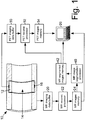
- a hybrid scanner includes a magnetic resonance (MR) scanner 10, which in the illustrated embodiment is a horizontal bore magnetic resonance scanner, and an integrated ring of positron emission tomography (PET) detectors 12. Both the MR scanner 10 and the integrated ring of PET detectors 12 are configured to acquire imaging data from a region of interest 14 disposed in an interior bore of the MR scanner 10.
- MR magnetic resonance
- PET positron emission tomography
- Both the MR scanner 10 and the integrated ring of PET detectors 12 are configured to acquire imaging data from a region of interest 14 disposed in an interior bore of the MR scanner 10.
- the horizontal bore MR scanner 10 with integral PET detectors 12 is shown with one-half of the MR bore and the corresponding half of the ring of PET detectors 12 cut away to reveal the bore interior and the remaining half of the integrated ring of PET detectors 12 ).
- the MR scanner 10 includes components such as a main magnet for generating a static (Bo) magnetic field, magnetic field gradient coils for superimposing magnetic field gradients, and one or more radio frequency coils for exciting and detecting magnetic resonance, such components not being shown for simplicity in FIGURE 1 .
- the ring of PET detectors 12 includes a backbone 16 of electronics for performing selected "on-board" operations such as optionally performing analog-to-digital conversion of electrical signals caused by radiation detection events, optionally performing digital time stamping of radiation detection events, and so forth. Alternatively, some of these operations may be performed by remote electronics (not shown).
- the MR scanner 10 acquires magnetic resonance (MR) data, such as k-space samples, using selected spatial encoding, and the acquired MR data are stored in a MR imaging data buffer 20.
- An MR reconstruction processor 22 processes the MR data using a reconstruction technique comporting with the selected spatial encoding.
- the spatial encoding is a conventional Cartesian encoding employing slice-selective gradients during excitation and phase- and readout-encoding gradients during the magnetic resonance signal decay and readout, respectively
- the MR reconstruction processor 22 suitably employs a Fourier transform-based reconstruction technique.
- the output of the MR reconstruction processor 22 is a MR image that is stored in an MR images memory 24 and is optionally displayed on a Computer 26 or other display device or otherwise utilized.
- the PET detectors 12 and associated on-board electronics 16 and/or remote electronics detect radiation detection events and perform energy and time windowing to identify substantially simultaneous 511 keV detection events indicative of electron-positron annihilation events.
- Each pair of substantially simultaneous 511 keV detection events defines a projection or line-of-response that connects the two 511 keV detection events.
- This set of data referred to as PET data or more generally as emission data, is stored in a PET imaging data buffer 30.
- the PET detectors 12 have sufficient temporal resolution to resolve time-of-flight time differences (or lack thereof) between the substantially simultaneous detection of two 511 keV gamma particles originating at the same electron-positron annihilation event, and the on-board and/or remote electronics are further configured to localize the electron-positron annihilation event along the line-of-response, thus generating time-of-flight PET data.
- the illustrated hybrid scanner 10, 12, 16 is an example. More generally, the techniques disclosed herein for performing emission data reconstruction are suitably practiced in conjunction with any PET scanner, or still more generally in conjunction with any scanner generating emission data, such as the illustrated PET detectors 12, a stand-alone PET detector, a gamma camera generating single-photon emission computed tomography (SPECT) data, or so forth.
- the techniques disclosed herein for performing emission data reconstruction are further suitably practiced in conjunction with any MR image of the same subject from which the emission data are acquired, such MR image being suitably acquired by the illustrated hybrid Scanner 10, 12, 16, or by a stand-alone MR scanner.
- a PET reconstruction processor 32 employs an iterative reconstruction technique to reconstruct the emission data acquired by the PET system 12, 16 (or more generally, by an radiation emission imaging system such as PET, SPECT, or so forth) to form a reconstructed emission image that is stored in a PET images memory 34 and optionally displayed on the computer 26 or another display device or otherwise utilized.
- the PET reconstruction processor 32 employs an attenuation map that accounts for emission losses caused by reabsorption of emitted radiation within the subject.
- a suitable attenuation map is generated using a combination of geometrical information provided by the MR image and attenuation value information derived from the emission data set itself.
- the MR image is segmented by an MR image segmentation processor 40 to identify one or more geometrical regions of the subject, and this geometrical information is suitably stored in an MR segmented images memory 42.
- the segmentation processor 40 can employ any suitable segmentation process to delineate anatomically distinct regions of the subject (assuming a human or animal subject having anatomy).
- Some suitable segmentation processes include, for example: threshold value-based segmentation methods; a Sobel operator-based segmentation method; region growing segmentation methods; watershed segmentation methods; model-based segmentation; or so forth.
- the one or more geometrical regions of the subject identified by the segmentation processor 40 are displayed on the vomputer 26 for human operator review, and the human operator has the option of using one or more interfacing devices of the computer 26 to adjust or otherwise modify the automatically identified one or more geometrical regions of the subject.
- the resulting one or more geometrical regions of the subject identified from the MR image by the segmentation processor 40 serve as input to the PET reconstruction processor 32, and the PET reconstruction processor 32 uses the geometrical information about the subject as represented by the identified one or more geometrical regions of the subject in constructing the attenuation map used in the emission data reconstruction.
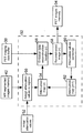
- An initial attenuation map generation operation 50 is performed by the PET reconstruction processor 32 to generate an initial attenuation map for use in an initial iteration of an iterative emission data reconstruction process.
- the initial attenuation map is constructed by assigning initial attenuation values 52 to the one or more geometrical regions of the subject identified by the MR image segmentation.
- the initial attenuation values 52 can be variously obtained.
- the one or more geometrical regions of the subject define an outer contour of the subject, and initially every voxel or pixel within the contour of the subject is assigned a default attenuation value, for example an attenuation value corresponding to that of water, and assigning a zero attenuation value to voxels or pixels disposed outside of the subject contour (assuming that the ambient is air, which has low absorption for most emission radiation of interest).
- the one or more geometrical regions of the subject may be a single region defining the subject contour, or may be a plurality of geometrical regions collectively defining the subject contour.
- the initial attenuation values 52 comprise a default attenuation value for each geometrical region selected based on a geometry of the geometrical regions.
- the anatomical identification of some or all of the geometrical regions may be identifiable based on the shape or location of those geometrical regions.
- different regions may be labeled as bone regions, fatty regions, muscle regions, or so forth, and a suitable default attenuation value assigned to each such labeled region based on its tissue type.
- a combination of these approaches may also be used to select the initial attenuation values 52, for example labeling some geometrical regions based on tissue type and assigning attenuation values based on the tissue type labels, and then assigning a default attenuation value such as the water attenuation value to any region whose tissue type is not determinable based on shape or location of the unidentifiable region.
- An initial iteration of an attenuation map 54 is generated by the attenuation values assignment operation 50.
- the attenuation map 54 is used by an emission data reconstruction iteration 56 performed by the PET reconstruction processor 32 to generate a reconstructed image 58.
- the emission data reconstruction process performed by the reconstruction processor 32 is iterative.
- the current iteration of the iterative emission data reconstruction process is indexed by the iteration index n and the attenuation map 54 used in the n th emission data reconstruction iteration 56 is indexed as the n th attenuation map 54, and the reconstructed image 58 output by the n th emission data reconstruction iteration 56 is indexed as the n th reconstructed image 58.
- Attenuation values corrections are computed in an operation 60, and these corrections are used to generate an updated attenuation map, that is, an ( n +1) th attenuation map 62, which is used to perform an ( n +1) th iteration of the iterative reconstruction process, and so forth.
- the iterative processing continues until a stopping criterion is met, such as a similarity measure between successive reconstructed images higher than a threshold value.
- the reconstructed image generated by the last iteration of the reconstruction process is output to the PET images memory 34 as the final reconstructed PET image.
- Substantially any iterative reconstruction algorithm suitable for reconstructing emission data can be employed for the iterations 56, such as a maximum likelihood expectation maximization (MLEM) algorithm.
- the attenuation values correction 60 can also employ any suitable correction algorithm, such as one of those disclosed in Nuyts et al., "Simultaneous Maximum A Posteriori Reconstruction of Attenuation and Activity Distributions from Emission Sinograms", IEEE Trans. On Medical Imaging vol. 18 no. 5, pp. 393-403 (1999 ), which is incorporated herein by reference in its entirety; or Hawkins et al., U.S. Pat. No. 6,310,968 which is also incorporated herein by reference in its entirety.
- n denotes the reconstruction iteration number as already described
- j indexes voxels in the region of interest
- i indexes pairs of the PET detectors 12 that detect substantially simultaneous 511 keV radiation (in the case of SPECT, the index i suitably indexes single detectors)
- ⁇ j denotes the estimated activity in the voxel indexed by j
- y i denotes the measured coincident photons in a detector pair indexed by i
- c ij denotes a system matrix entry indicative of sensitivity of the detector pair indexed by i toward the voxel indexed by j
- a i exp ⁇ ⁇ k
- R r denotes a geometrical region indexed by r where the index r runs over the regions identified by the MR image segmentation stored in the memory 42
- ⁇ ⁇ r n denotes the region-specific attenuation coefficient for the n th attenuation map 54
- ⁇ ⁇ r n + 1 denotes the region-specific attenuation coefficient for the ( n +1) th attenuation map 62
- the fractional term in Equation (6) represents the average attenuation value correction for the region R r .
- the attenuation map update of Equation (6) operates on a per-geometrical region basis, with each geometrical region R r assigned a single updated attenuation value ⁇ ⁇ r n + 1 for all pixels or voxels of the region.
- the attenuation map update of Equation (6) assigns a generally different attenuation value to each of the geometrical regions.
- generally different it is meant that the attenuation map update assigns an attenuation value to each region, which is typically different from the attenuation values assigned to other regions but which may in some instances be the same as an attenuation value assigned to another region or regions. For example, if two different regions correspond to a common tissue type (for example, both representing bone regions) it is likely that the attenuation map update may assign the same or similar attenuation values to these two different regions corresponding to the same tissue type.
- This approach allows initial convergence to an attenuation map that is optimized with respect to the regions, which entails optimizing relatively few parameters and should give a good approximation to the actual subject attenuation; then to follow up with the more computationally intensive per-pixel or per-voxel optimization starting from the (close to correct) attenuation map optimized with respect to the regions.
- the timing of the switch from per-region attenuation map updating to per-pixel or per-voxel attenuation map updating can be based on various criteria.
- per-region attenuation map updating is used for a fixed number of first iterations, for example for the first three iterations, and per-pixel or per-voxel updating is then used for the remaining iterations, for example the fourth and later iterations.
- a switch criterion can be monitored, such as calculating the maximum change in the attenuation value of any region from one iteration to the next. When this maximum change falls below a threshold, thus indicating that the per-region attenuation map optimization is close to convergence, the switch is made to per-pixel or per-voxel updating.
- a per-region attenuation value update can be performed for pixels or voxels in regions believed to have substantially uniform absorption, while a per-pixel or per-voxel attenuation value update can be performed for pixels or voxels in regions that are expected to have more non-uniform absorption.
- the assignment of a region as uniform or non-uniform can be based on a priori knowledge of the likely tissue type or organ identity of the region, or can be based on quantitative measures such as the variation of the correction field K j across the region.
- any region for which the correction field K j varies by more than a threshold amount is updated on a per-pixel or per-voxel basis, under the assumption that the large variation in the correction field K j across the region indicates that the region has non-uniform absorption.
- the values ⁇ ⁇ j n + 1 or ⁇ j n + 1 are calculated as described herein, but the attenuation values assigned to the regions or voxels or pixels of the attenuation map are selected from a group of standard values based on the calculated ⁇ ⁇ j n + 1 or ⁇ j n + 1 values.
- the MR image and the emission data employ the same subject coordinates system. This is likely to be the case for the illustrated hybrid scanner 10, 12, 16.
- correspondence of the MR and emission coordinate systems can be achieved using fiducial markers disposed on the subject and visible in both the MR and emission systems.
- the PET data are optionally initially "coarse" reconstructed without accounting for absorption and the resulting "coarse" image is spatially aligned or registered with the MR image to determine a common subject coordinates system for the MR image and the emission data.
- the iterative emission data reconstruction algorithm disclosed with reference to FIGURE 2 can then be applied to the spatially registered MR image and emission data.
- the iterative updating of the attenuation map also includes adjusting the size and/or shape of the geometrical regions.
- a shape model is defined for at least one of the geometrical regions, using polygon- or spline-based surface models.
- the shape model can be fitted to the relevant segment of the segmented MR image to define initial shape model parameters.
- the attenuation values correction 60 is used to update the shape model.
- the correction field K j can be expected to be large at boundaries where the current surface model does not conform with the region shape as represented in the emission data.
- the shape model can then be iteratively adjusted according to information from the iteratively generated correction field K j .
- Such geometry correction is advantageous if, for example, to accommodate changes in the patient between the MR and the PET data acquisitions. Such changes are known to be relatively frequent in the abdominal region and in some other regions of a human subject.
- the correction field K j can be used, for example, to adapt the shape of the region representing the stomach, the belly outer contour, or so forth to accommodate typical changes that may occur between data acquisitions.
- the various computational components 22, 32, 40 disclosed herein can be implemented in various ways, for example by a computer or other device including a digital processor and programmed or including firmware to perform the disclosed processing, or by hybrid or analog circuitry configured to perform the disclosed processing or portions thereof, or so forth.
- the computational components 22, 32, 40 may be embodied by the illustrated computer 26 having suitable firmware or programming.
- the MR and emission data and image processing methods disclosed herein can be implemented by such a processor or other hardware, and/or can be embodied as a storage medium storing instructions that when executed by such a processor or other hardware perform the disclosed methods.
- Such a storage medium may be embodied by one or more types of storage media, such as one or more of: a magnetic disk; an optical disk; a FLASH memory or other electrostatic memory; a random access memory (RAM); a read-only memory (ROM); or so forth.
- a magnetic disk such as one or more of: a magnetic disk; an optical disk; a FLASH memory or other electrostatic memory; a random access memory (RAM); a read-only memory (ROM); or so forth.
Description
- The following relates to the imaging arts, emission tomography arts, positron emission tomography (PET) arts, single photon emission computed tomography (SPECT) arts, magnetic resonance arts, and related arts. It is described with particular reference to PET/MR systems and synergistic PET/MR imaging applications, but will find application in PET imaging, SPECT imaging, and other radiation emission-based imaging modalities, and in reconstruction techniques for same.
- Imaging by emission tomography, such as PET or SPECT, is enhanced by accounting for absorption in the imaged subject using a suitable attenuation map. Emission tomography performed in combination with transmissive computed tomography (CT) advantageously benefits from the availability of radiation attenuation data provided by the CT modality. A reconstructed CT image is essentially an attenuation map of the imaged subject for the x-ray radiation used in generating the CT image data. Although the x-ray radiation used in CT is generally not identical with the 511 keV radiation measured in PET or the emissions measured in SPECT or other emission tomography techniques, it is known that an attenuation map for the emission tomography can be generated from the reconstructed transmission CT image by suitably scaling the CT grayscale levels to account for the differences in radiation type.
- There is also interest in performing emission tomography in synergistic combination with magnetic resonance (MR) imaging. Here, one does not have the transmission CT image from which to generate an attenuation map. Attempts to use an MR image as an attenuation map for analyzing PET or SPECT data have been unsuccessful. This is because the contrast mechanism in MR is fundamentally different from that of PET or SPECT (or CT, for that matter). As a consequence, it cannot be said that a "dark" MR pixel necessarily corresponds to either high or low attenuation. For example, bone tissue and air have similar grayscale intensities for some MR imaging modes, but the attenuation of emission radiation by bone is much higher than the attenuation of air.
- In such circumstances, it has been contemplated to generate an attenuation map using various techniques. In one contemplated approach, an attenuation "atlas" of a typical subject, for example of a typical human subject, is employed. The attenuation atlas identifies attenuation of various components or regions of the typical subject. However, actual subjects, such as actual human subjects, vary substantially, and it is not straightforward to adapt the attenuation atlas to a particular subject.
- Another contemplated approach employs machine learning of typical attenuation patterns to construct a transform algorithm for transforming an MR image into an attenuation map suitable for use in PET. This approach is difficult to implement, and the empirical nature of the machine learning approach can lead to errors that are difficult to predict or estimate.
- Another approach has been to incorporate generation of the attenuation map with reconstruction of the emission data. See, for example,
Hawkins et al., U.S. Pat. No. 6,310,968 and Nuyts et al., "Simultaneous Maximum A Posteriori Reconstruction of Attenuation and Activity Distributions from Emission Sinograms", IEEE Trans, on Medical Imaging vol. 18 no. 5 pp. 393-403 (1999). These approaches advantageously does not require use of an externally supplied attenuation map. However, they also do not make use of information available from corresponding MR images. Artifacts are sometimes observed in images reconstructed using these single-modality techniques. The following provides a new and improved apparatuses and methods which overcome the above-referenced problems and others. In "Strategies for attenuation compensation in neurological PET studies" by H. Zaidi et al. (Neurolmage Vol. 34, No. 2, pages 518-541) a physical and methodological basis of photon attenuation is discussed and state of the art developments in algorithms used to derive the attenuation map aiming at accurate attenuation compensation of brain PET data are summarized. Future prospects, research trends and challenges are identified and directions for future research are discussed. - In accordance with one disclosed aspect, a method operating in conjunction with a magnetic resonance (MR) image of a subject and emission data acquired from the subject is disclosed, the method comprising: identifying one or more geometrical regions of the subject using the MR image; and generating an attenuation map of the subject by assigning initial attenuation values to the geometrical regions; the method further comprising the steps of: (i) reconstructing the emission data to generate an emission image of the subject utilizing the attenuation map;(ii) updating the attenuation values for the geometrical regions based on corrections calculated using the emission image of the subject; and (iii) iterating steps (i) and (ii) to iteratively generate a reconstructed emission image of the subject; wherein in the iterative reconstruction a geometry of at least one of the geometrical regions is represented by a shape model, which shape model is a polygon- or spline-based surface model, and which shape model is updated in each iteration based on the attenuation values corrections calculated in step (ii) of the iterative reconstruction.
- In accordance with another disclosed aspect, an emission data reconstruction processor is disclosed which is configured to perform the method of the immediately preceding paragraph.
- In accordance with another disclosed aspect, an apparatus is disclosed, comprising a reconstruction processor configured to identify one or more geometrical regions of a subject using an MR image of the subject, generate an attenuation map of the subject by assigning initial attenuation values to the geometrical regions of the subject, and to: (i) process emission data acquired from the subject to generate an emission image of the subject, the processing employing the attenuation map of the subject; (ii) update the attenuation map based on corrections calculated using the emission image of the subject; and (iii) iterate operations (i) and (ii) to iteratively generate a reconstructed emission image of the subject, wherein in the iterative reconstruction a geometry of at least one of the geometrical regions is represented by a shape model, which shape model is a polygon- or spline-based surface model, and which shape model is updated in each iteration based on the attenuation map corrections calculated in operation (ii) of the iterative reconstruction.
- One advantage resides in more accurate image reconstruction of PET, SPECT, or other emission data, resulting in quantitative image information as needed for many novel diagnostic applications.
- Another advantage resides in synergistic coupling of MR data with PET, SPECT, or other emission data to enhance image reconstruction of the latter.
- Further advantages will be apparent to those of ordinary skill in the art upon reading and understand the following detailed description.
-
FIGURE 1 diagrammatically shows a hybrid MR/PET imaging system including a PET reconstruction processor that utilizes an attenuation map having geometry derived from a corresponding MR image and attenuation values derived iteratively from the PET emission data. -
FIGURE 2 diagrammatically shows processing performed by the PET reconstruction processor. - With reference to
FIGURE 1 , a hybrid scanner includes a magnetic resonance (MR)scanner 10, which in the illustrated embodiment is a horizontal bore magnetic resonance scanner, and an integrated ring of positron emission tomography (PET)detectors 12. Both theMR scanner 10 and the integrated ring ofPET detectors 12 are configured to acquire imaging data from a region ofinterest 14 disposed in an interior bore of theMR scanner 10. (In diagrammaticFIGURE 1 , the horizontalbore MR scanner 10 withintegral PET detectors 12 is shown with one-half of the MR bore and the corresponding half of the ring ofPET detectors 12 cut away to reveal the bore interior and the remaining half of the integrated ring of PET detectors 12). TheMR scanner 10 includes components such as a main magnet for generating a static (Bo) magnetic field, magnetic field gradient coils for superimposing magnetic field gradients, and one or more radio frequency coils for exciting and detecting magnetic resonance, such components not being shown for simplicity inFIGURE 1 . The ring ofPET detectors 12 includes abackbone 16 of electronics for performing selected "on-board" operations such as optionally performing analog-to-digital conversion of electrical signals caused by radiation detection events, optionally performing digital time stamping of radiation detection events, and so forth. Alternatively, some of these operations may be performed by remote electronics (not shown). - The MR scanner 10 acquires magnetic resonance (MR) data, such as k-space samples, using selected spatial encoding, and the acquired MR data are stored in a MR
imaging data buffer 20. AnMR reconstruction processor 22 processes the MR data using a reconstruction technique comporting with the selected spatial encoding. For example, if the spatial encoding is a conventional Cartesian encoding employing slice-selective gradients during excitation and phase- and readout-encoding gradients during the magnetic resonance signal decay and readout, respectively, then theMR reconstruction processor 22 suitably employs a Fourier transform-based reconstruction technique. The output of theMR reconstruction processor 22 is a MR image that is stored in anMR images memory 24 and is optionally displayed on aComputer 26 or other display device or otherwise utilized. - The
PET detectors 12 and associated on-board electronics 16 and/or remote electronics (not shown) detect radiation detection events and perform energy and time windowing to identify substantially simultaneous 511 keV detection events indicative of electron-positron annihilation events. Each pair of substantially simultaneous 511 keV detection events defines a projection or line-of-response that connects the two 511 keV detection events. This set of data, referred to as PET data or more generally as emission data, is stored in a PETimaging data buffer 30. - In some embodiments, the
PET detectors 12 have sufficient temporal resolution to resolve time-of-flight time differences (or lack thereof) between the substantially simultaneous detection of two 511 keV gamma particles originating at the same electron-positron annihilation event, and the on-board and/or remote electronics are further configured to localize the electron-positron annihilation event along the line-of-response, thus generating time-of-flight PET data. - The illustrated
hybrid scanner PET detectors 12, a stand-alone PET detector, a gamma camera generating single-photon emission computed tomography (SPECT) data, or so forth. The techniques disclosed herein for performing emission data reconstruction are further suitably practiced in conjunction with any MR image of the same subject from which the emission data are acquired, such MR image being suitably acquired by the illustratedhybrid Scanner - With continuing reference to
FIGURE 1 , aPET reconstruction processor 32 employs an iterative reconstruction technique to reconstruct the emission data acquired by thePET system 12, 16 (or more generally, by an radiation emission imaging system such as PET, SPECT, or so forth) to form a reconstructed emission image that is stored in aPET images memory 34 and optionally displayed on thecomputer 26 or another display device or otherwise utilized. - To perform the emission image reconstruction, the
PET reconstruction processor 32 employs an attenuation map that accounts for emission losses caused by reabsorption of emitted radiation within the subject. A suitable attenuation map is generated using a combination of geometrical information provided by the MR image and attenuation value information derived from the emission data set itself. - Toward this end, the MR image is segmented by an MR
image segmentation processor 40 to identify one or more geometrical regions of the subject, and this geometrical information is suitably stored in an MR segmentedimages memory 42. Thesegmentation processor 40 can employ any suitable segmentation process to delineate anatomically distinct regions of the subject (assuming a human or animal subject having anatomy). Some suitable segmentation processes include, for example: threshold value-based segmentation methods; a Sobel operator-based segmentation method; region growing segmentation methods; watershed segmentation methods; model-based segmentation; or so forth. Optionally, the one or more geometrical regions of the subject identified by thesegmentation processor 40 are displayed on thevomputer 26 for human operator review, and the human operator has the option of using one or more interfacing devices of thecomputer 26 to adjust or otherwise modify the automatically identified one or more geometrical regions of the subject. The resulting one or more geometrical regions of the subject identified from the MR image by thesegmentation processor 40 serve as input to thePET reconstruction processor 32, and thePET reconstruction processor 32 uses the geometrical information about the subject as represented by the identified one or more geometrical regions of the subject in constructing the attenuation map used in the emission data reconstruction. - With continuing reference to
FIGURE 1 and with further reference toFIGURE 2 , a suitable reconstruction process employed by thePET reconstruction processor 32 is described. An initial attenuationmap generation operation 50 is performed by thePET reconstruction processor 32 to generate an initial attenuation map for use in an initial iteration of an iterative emission data reconstruction process. The initial attenuation map is constructed by assigninginitial attenuation values 52 to the one or more geometrical regions of the subject identified by the MR image segmentation. Theinitial attenuation values 52 can be variously obtained. In one approach, the one or more geometrical regions of the subject define an outer contour of the subject, and initially every voxel or pixel within the contour of the subject is assigned a default attenuation value, for example an attenuation value corresponding to that of water, and assigning a zero attenuation value to voxels or pixels disposed outside of the subject contour (assuming that the ambient is air, which has low absorption for most emission radiation of interest). In such an embodiment, the one or more geometrical regions of the subject may be a single region defining the subject contour, or may be a plurality of geometrical regions collectively defining the subject contour. - In other embodiments, the initial attenuation values 52 comprise a default attenuation value for each geometrical region selected based on a geometry of the geometrical regions. For example, the anatomical identification of some or all of the geometrical regions may be identifiable based on the shape or location of those geometrical regions. In this way, for example, different regions may be labeled as bone regions, fatty regions, muscle regions, or so forth, and a suitable default attenuation value assigned to each such labeled region based on its tissue type.
- A combination of these approaches may also be used to select the initial attenuation values 52, for example labeling some geometrical regions based on tissue type and assigning attenuation values based on the tissue type labels, and then assigning a default attenuation value such as the water attenuation value to any region whose tissue type is not determinable based on shape or location of the unidentifiable region.
- An initial iteration of an attenuation map 54 is generated by the attenuation values
assignment operation 50. The attenuation map 54 is used by an emissiondata reconstruction iteration 56 performed by thePET reconstruction processor 32 to generate areconstructed image 58. The emission data reconstruction process performed by thereconstruction processor 32 is iterative. InFIGURE 2 , the current iteration of the iterative emission data reconstruction process is indexed by the iteration index n and the attenuation map 54 used in the nth emissiondata reconstruction iteration 56 is indexed as the nth attenuation map 54, and thereconstructed image 58 output by the nth emissiondata reconstruction iteration 56 is indexed as the nth reconstructedimage 58. - Based on the nth reconstructed
image 58, attenuation values corrections are computed in an operation 60, and these corrections are used to generate an updated attenuation map, that is, an (n+1) thattenuation map 62, which is used to perform an (n+1) th iteration of the iterative reconstruction process, and so forth. The iterative processing continues until a stopping criterion is met, such as a similarity measure between successive reconstructed images higher than a threshold value. The reconstructed image generated by the last iteration of the reconstruction process is output to thePET images memory 34 as the final reconstructed PET image. Although not illustrated, it is also contemplated to store, display, or otherwise utilize the last generated attenuation map. - Substantially any iterative reconstruction algorithm suitable for reconstructing emission data can be employed for the
iterations 56, such as a maximum likelihood expectation maximization (MLEM) algorithm. The attenuation values correction 60 can also employ any suitable correction algorithm, such as one of those disclosed in Nuyts et al., "Simultaneous Maximum A Posteriori Reconstruction of Attenuation and Activity Distributions from Emission Sinograms", IEEE Trans. On Medical Imaging vol. 18 no. 5, pp. 393-403 (1999), which is incorporated herein by reference in its entirety; orHawkins et al., U.S. Pat. No. 6,310,968 which is also incorporated herein by reference in its entirety. A suitable approach for the nth emission data reconstruction iteration 56 employing MLEM is as follows:


ij denotes the average weighting factor towards time-of-flight information depending upon the detector pair indexed by i and the voxel indexed by j. - A suitable approach for performing the attenuation values correction 60 is to forward project the updated activity image to generate projection data or lines-of-response yi, for the detector pairs i, and to compute a correction field Kj according to:


memory 42;

attenuation map 62; and the fractional term in Equation (6) represents the average attenuation value correction for the region Rr. - The attenuation map update of Equation (6) operates on a per-geometrical region basis, with each geometrical region Rr assigned a single updated attenuation value

- In an alternative approach, the attenuation map update can be performed on a per-pixel or per-voxel basis, by updating each pixel or voxel j of the attenuation map according to

- Another contemplated variation is to perform a per-region attenuation map update in accordance with Equation (6) for the first few iterations, and then to switch over to a per-pixel or per-voxel attenuation map update in accordance with

- In yet another contemplated variation, a per-region attenuation value update can be performed for pixels or voxels in regions believed to have substantially uniform absorption, while a per-pixel or per-voxel attenuation value update can be performed for pixels or voxels in regions that are expected to have more non-uniform absorption. The assignment of a region as uniform or non-uniform can be based on a priori knowledge of the likely tissue type or organ identity of the region, or can be based on quantitative measures such as the variation of the correction field Kj across the region. In the latter approach, for example, any region for which the correction field Kj varies by more than a threshold amount is updated on a per-pixel or per-voxel basis, under the assumption that the large variation in the correction field Kj across the region indicates that the region has non-uniform absorption.
- Still further, updates other than those of Equations (5) and (6) or the update


- In the foregoing, it is assumed that the MR image and the emission data employ the same subject coordinates system. This is likely to be the case for the illustrated
hybrid scanner FIGURE 2 can then be applied to the spatially registered MR image and emission data. - In some contemplated embodiments, the iterative updating of the attenuation map also includes adjusting the size and/or shape of the geometrical regions. In the approach of the invention, a shape model is defined for at least one of the geometrical regions, using polygon- or spline-based surface models. The shape model can be fitted to the relevant segment of the segmented MR image to define initial shape model parameters. Thereafter, when the attenuation map is updated in each iteration the attenuation values correction 60 is used to update the shape model. For example, the correction field Kj can be expected to be large at boundaries where the current surface model does not conform with the region shape as represented in the emission data. The shape model can then be iteratively adjusted according to information from the iteratively generated correction field Kj . Such geometry correction is advantageous if, for example, to accommodate changes in the patient between the MR and the PET data acquisitions. Such changes are known to be relatively frequent in the abdominal region and in some other regions of a human subject. The correction field Kj can be used, for example, to adapt the shape of the region representing the stomach, the belly outer contour, or so forth to accommodate typical changes that may occur between data acquisitions.
- The various
computational components computational components computer 26 having suitable firmware or programming. The MR and emission data and image processing methods disclosed herein can be implemented by such a processor or other hardware, and/or can be embodied as a storage medium storing instructions that when executed by such a processor or other hardware perform the disclosed methods. Such a storage medium may be embodied by one or more types of storage media, such as one or more of: a magnetic disk; an optical disk; a FLASH memory or other electrostatic memory; a random access memory (RAM); a read-only memory (ROM); or so forth. - The invention has been described with reference to the preferred embodiments. Modifications and alterations may occur to others upon reading and understanding the preceding detailed description. It is intended that the invention be construed as including all such modifications and alterations insofar as they come within the scope of the appended claims.
Claims (13)
- A method operating in conjunction with a magnetic resonance (MR) image of a subject and emission data acquired from the subject, the method comprising:identifying one or more geometrical regions of the subject using the MR image; andgenerating an attenuation map of the subject by assigning initial attenuation values to the geometrical regions;the method further comprising the steps of:(i) reconstructing the emission data to generate an emission image of the subject utilizing the attenuation map;(ii) updating the attenuation values for the geometrical regions based on corrections calculated using the emission image of the subject; and(iii) iterating steps (i) and (ii) to iteratively generate a reconstructed emission image of the subject; wherein in the iterative reconstruction a geometry of at least one of the geometrical regions is represented by a shape model, which shape model is a polygon- or spline-based surface model, and which shape model is updated in each iteration based on the attenuation values corrections calculated in step (ii) of the iterative reconstruction.
- The method as set forth in claim 1, further comprising:
acquiring the emission data from the subject using one of positron emission tomography (PET) and single photon emission computed tomography (SPECT). - The method as set forth in claim 1, further comprising:
generating initial attenuation values for the geometrical regions, the initial attenuation values being one of:(i) a same attenuation value for all geometrical regions, and(ii) a default attenuation value for each geometrical region selected based on at least one of shape, position, and size of the geometrical regions. - The method as set forth in any one of claims 1-3, wherein the iterative updating of the attenuation values for the geometrical regions comprises:
updating attenuation values on a per-pixel or per-voxel basis for at least some iterations of the iterative reconstruction. - The method as set forth in any one of claims 1-4, wherein the iterative updating of the attenuation values for the geometrical regions comprises:
updating attenuation values on a per-region basis for at least some iterations of the iterative reconstruction, wherein updating attenuation values on a per-region basis comprises assigning the same attenuation value to all pixels or voxels of a given region. - The method as set forth in claim 1, wherein the updating of the attenuation values comprises:forward projecting the updated emission image generated by the most recent iteration of the iterative reconstruction to generate forward projection data; andcalculating attenuation value corrections based on comparison of the forward projection data and the emission data acquired from the subject.
- An apparatus comprising:a reconstruction processor (32, 40) configured to identify one or more geometrical regions of a subject using an MR image of the subject, generate an attenuation map (54) of the subject by assigning initial attenuation values (52) to the geometrical regions of the subject, and to:(i) process (56) emission data acquired from the subject to generate an emission image (58) of the subject, the processing employing the attenuation map of the subject,(ii) update (60) the attenuation map based on corrections calculated using the emission image of the subject, and(iii) iterate operations (i) and (ii) to iteratively generate a reconstructed emission image of the subject,wherein in the iterative reconstruction a geometry of at least one of the geometrical regions is represented by a shape model, which shape model is a polygon- or spline-based surface model, and which shape model is updated in each iteration based on the attenuation map corrections calculated in operation (ii) of the iterative reconstruction.
- The apparatus as set forth in claim 7, wherein the update operation (ii) (60) comprises:(ii)(a) forward projecting the emission image (58) of the subject to generate forward projection data, and(ii)(b) calculating a correction of the attenuation map (54) based on comparison of the forward projection data and the emission data acquired from the subject.
- The apparatus as set forth in any one of claims 7-8, further comprising:a MR Scanner (10) configured to generate the MR image of the subject; andsingle photon emission computed tomography (SPECT) or positron emission tomography (PET) detectors (12) configured to acquire the emission data acquired from the subject.
- The apparatus as set forth in any one of claims 7-9, wherein the reconstruction processor (32, 40) comprises an MR image segmentation processor (40) configured to segment the MR image of the subject to identify the one or more geometrical regions of the subject.
- The apparatus as set forth in any one of claims 7-10, wherein the reconstruction processor (32, 40) is configured to identify a plurality of geometrical regions of the subject using the MR image of the subject, and the attenuation map update operation (ii) (60) assigns a generally different attenuation value to each of the geometrical regions.
- The apparatus as set forth in any one of claims 7-11, wherein the attenuation map update operation (ii) (60) assigns a generally different attenuation value to each pixel or voxel of the attenuation map (54).
- The apparatus as set forth in any one of claims 7-12, wherein the reconstruction processor (32, 40) is configured to identify a plurality of geometrical regions of the subject using the MR image of the subject, and the attenuation map update operation (ii) (60) assigns:attenuation values on a per-geometrical region basis for a first one or more of the iterations (iii) andattenuation values on a per-pixel or per-voxel basis for a subsequent one or more of the iterations (iii).
Applications Claiming Priority (2)
| Application Number | Priority Date | Filing Date | Title |
|---|---|---|---|
| US9825408P | 2008-09-19 | 2008-09-19 | |
| PCT/IB2009/053946 WO2010032168A2 (en) | 2008-09-19 | 2009-09-09 | Method for generation of attenuation map in pet-mr |
Publications (2)
| Publication Number | Publication Date |
|---|---|
| EP2340524A2 EP2340524A2 (en) | 2011-07-06 |
| EP2340524B1 true EP2340524B1 (en) | 2019-06-05 |
Family
ID=42039964
Family Applications (1)
| Application Number | Title | Priority Date | Filing Date |
|---|---|---|---|
| EP09787150.3A Not-in-force EP2340524B1 (en) | 2008-09-19 | 2009-09-09 | Method for generation of attenuation map in pet-mr |
Country Status (5)
| Country | Link |
|---|---|
| US (1) | US8600136B2 (en) |
| EP (1) | EP2340524B1 (en) |
| JP (1) | JP5530446B2 (en) |
| CN (1) | CN102934143B (en) |
| WO (1) | WO2010032168A2 (en) |
Families Citing this family (32)
| Publication number | Priority date | Publication date | Assignee | Title |
|---|---|---|---|---|
| US9453922B2 (en) * | 2008-09-09 | 2016-09-27 | Multi-Magnetics Incorporated | System and method for correcting attenuation in hybrid medical imaging |
| DE102008047840B4 (en) * | 2008-09-18 | 2018-08-30 | Siemens Healthcare Gmbh | Method for the at least partial determination and / or adaptation of an attenuation map used for the attenuation correction of positron emission tomography image data sets in a combined magnetic resonance positron emission tomography device |
| US8242777B2 (en) * | 2009-09-28 | 2012-08-14 | Siemens Aktiengesellschaft | Calibration of an emission tomography subsystem |
| CN103069456B (en) | 2010-08-25 | 2016-11-16 | 皇家飞利浦电子股份有限公司 | Bimodal imaging including quality metrics |
| EP2663964A1 (en) * | 2011-01-10 | 2013-11-20 | Koninklijke Philips N.V. | Dual-energy tomographic imaging system |
| US9336613B2 (en) * | 2011-05-24 | 2016-05-10 | Koninklijke Philips N.V. | Apparatus for generating assignments between image regions of an image and element classes |
| US9324167B2 (en) * | 2011-05-24 | 2016-04-26 | Koninklijke Philips N.V. | Apparatus and method for generating an attenuation correction map |
| US8913810B2 (en) * | 2011-07-26 | 2014-12-16 | Siemens Medical Solutions Usa, Inc. | Simultaneous reconstruction of emission activity and attenuation coefficient distribution from TOF data, acquired with external shell source |
| ES2692163T3 (en) | 2012-03-28 | 2018-11-30 | Shimadzu Corporation | Method to generate corrected image in pet absorption from rm image and computer program |
| RU2608975C2 (en) | 2012-03-29 | 2017-01-30 | Конинклейке Филипс Н.В. | Method of magnetic resonance imaging (mri) for assigning for individual pixels or voxels the specific for tissue values of positron emission tomography (pet) |
| KR101331504B1 (en) * | 2012-05-22 | 2013-11-26 | 서울대학교산학협력단 | Nuclear medicine emission imaging system and method for attenuation correction of nuclear medicine using single transmission scan data |
| US8958660B2 (en) * | 2012-06-22 | 2015-02-17 | General Electric Company | Method and apparatus for iterative reconstruction |
| US20150065854A1 (en) * | 2012-10-31 | 2015-03-05 | General Electric Company | Joint estimation of attenuation and activity information using emission data |
| US9928617B2 (en) * | 2012-11-08 | 2018-03-27 | The General Hospital Corporation | System and method for multi-modality time-of-flight attenuation correction |
| CN103908278B (en) * | 2013-01-06 | 2017-07-28 | 上海联影医疗科技有限公司 | Image rebuilding method and device, medical imaging system |
| EP3004909B1 (en) * | 2013-06-07 | 2020-08-26 | Koninklijke Philips N.V. | Visual pre-scan patient information for magnetic resonance protocol |
| WO2014203192A2 (en) * | 2013-06-20 | 2014-12-24 | Koninklijke Philips N.V. | Cortical bone segmentation from mr dixon data |
| EP3210187B1 (en) * | 2014-10-20 | 2023-08-30 | Koninklijke Philips N.V. | Classified truncation compensation |
| CN104700438B (en) * | 2014-11-21 | 2017-06-06 | 上海联影医疗科技有限公司 | Image rebuilding method and device |
| US9474495B2 (en) | 2014-12-22 | 2016-10-25 | General Electric Company | System and method for joint estimation of attenuation and activity information |
| US20160327622A1 (en) * | 2015-05-05 | 2016-11-10 | General Electric Company | Joint reconstruction of activity and attenuation in emission tomography using magnetic-resonance-based priors |
| US10078889B2 (en) | 2015-08-25 | 2018-09-18 | Shanghai United Imaging Healthcare Co., Ltd. | System and method for image calibration |
| CN106456098B (en) | 2016-07-08 | 2019-11-19 | 上海联影医疗科技有限公司 | The generation method and system of decay pattern |
| US10210634B2 (en) * | 2016-07-20 | 2019-02-19 | Shanghai United Imaging Healthcare Co., Ltd. | System and method for segmenting medical image |
| US9706972B1 (en) * | 2016-09-28 | 2017-07-18 | General Electric Company | Systems and methods for reconstruction of emission activity image |
| US10593071B2 (en) * | 2017-04-14 | 2020-03-17 | Siemens Medical Solutions Usa, Inc. | Network training and architecture for medical imaging |
| US11403792B2 (en) | 2017-06-19 | 2022-08-02 | Washington University | Deep learning-assisted image reconstruction for tomographic imaging |
| KR101958099B1 (en) * | 2017-07-31 | 2019-07-04 | 인제대학교 산학협력단 | Attenuation correction method using time-of-flight information in positron emission tomography |
| WO2019185498A1 (en) * | 2018-03-26 | 2019-10-03 | Koninklijke Philips N.V. | Automatic fault detection in hybrid imaging |
| EP3640662A1 (en) * | 2018-10-16 | 2020-04-22 | Koninklijke Philips N.V. | Magnetic resonance imaging using motion-compensated image reconstruction |
| KR102542505B1 (en) * | 2020-11-17 | 2023-06-13 | (주)자비스 | System, method and program for creating tranining data using x-ray attenuation equation and method for detecting foreighn material using thereof |
| US11854126B2 (en) * | 2021-07-07 | 2023-12-26 | Siemens Medical Solutions Usa, Inc. | Methods and apparatus for deep learning based image attenuation correction |
Family Cites Families (17)
| Publication number | Priority date | Publication date | Assignee | Title |
|---|---|---|---|---|
| US5376795A (en) * | 1990-07-09 | 1994-12-27 | Regents Of The University Of California | Emission-transmission imaging system using single energy and dual energy transmission and radionuclide emission data |
| US5672877A (en) * | 1996-03-27 | 1997-09-30 | Adac Laboratories | Coregistration of multi-modality data in a medical imaging system |
| WO1999056150A1 (en) * | 1998-04-27 | 1999-11-04 | Duke University | Transmission scanning technique for gamma camera coincidence imaging |
| US6310968B1 (en) * | 1998-11-24 | 2001-10-30 | Picker International, Inc. | Source-assisted attenuation correction for emission computed tomography |
| IL130318A0 (en) * | 1999-06-06 | 2000-06-01 | Elgems Ltd | Pet and spect systems with attenuation correction |
| DE10231061A1 (en) * | 2002-07-10 | 2004-01-22 | Philips Intellectual Property & Standards Gmbh | Process and system for improving the information content in an image |
| AU2003276658A1 (en) * | 2002-11-04 | 2004-06-07 | V-Target Technologies Ltd. | Apparatus and methods for imaging and attenuation correction |
| US7197171B2 (en) * | 2003-02-19 | 2007-03-27 | Elgems Ltd. | Nuclear imaging |
| US20060004274A1 (en) * | 2004-06-30 | 2006-01-05 | Hawman Eric G | Fusing nuclear medical images with a second imaging modality |
| EP1828981A2 (en) * | 2004-12-15 | 2007-09-05 | Koninklijke Philips Electronics N.V. | Registration of multi-modality images |
| EP1828808B1 (en) * | 2004-12-17 | 2010-04-21 | Koninklijke Philips Electronics N.V. | Truncation compensation algorithm for iterative reconstruction |
| US7402807B2 (en) * | 2005-11-02 | 2008-07-22 | Siemens Medical Solutions Usa, Inc. | Method for reducing an electronic time coincidence window in positron emission tomography |
| US7348564B2 (en) * | 2005-12-12 | 2008-03-25 | General Electric Company | Multi modality imaging methods and apparatus |
| US20080135769A1 (en) * | 2006-11-22 | 2008-06-12 | Rosen Bruce R | Attenuation correction of pet image using image data acquired with an mri system |
| DE102007034953B4 (en) * | 2007-07-26 | 2016-09-22 | Siemens Healthcare Gmbh | A method for recording movements of a patient and associated medical device |
| CN100508891C (en) * | 2007-09-04 | 2009-07-08 | 陈武凡 | Maximum posteriori optimizing image rebuilding method in PET imaging |
| US8098916B2 (en) * | 2007-10-30 | 2012-01-17 | General Electric Company | System and method for image-based attenuation correction of PET/SPECT images |
-
2009
- 2009-09-09 WO PCT/IB2009/053946 patent/WO2010032168A2/en active Application Filing
- 2009-09-09 US US13/062,224 patent/US8600136B2/en not_active Expired - Fee Related
- 2009-09-09 JP JP2011527435A patent/JP5530446B2/en not_active Expired - Fee Related
- 2009-09-09 CN CN200980136469.5A patent/CN102934143B/en not_active Expired - Fee Related
- 2009-09-09 EP EP09787150.3A patent/EP2340524B1/en not_active Not-in-force
Non-Patent Citations (1)
| Title |
|---|
| None * |
Also Published As
| Publication number | Publication date |
|---|---|
| JP5530446B2 (en) | 2014-06-25 |
| US20110158497A1 (en) | 2011-06-30 |
| US8600136B2 (en) | 2013-12-03 |
| EP2340524A2 (en) | 2011-07-06 |
| WO2010032168A3 (en) | 2014-04-24 |
| JP2012506530A (en) | 2012-03-15 |
| CN102934143B (en) | 2016-04-27 |
| CN102934143A (en) | 2013-02-13 |
| WO2010032168A2 (en) | 2010-03-25 |
Similar Documents
| Publication | Publication Date | Title |
|---|---|---|
| EP2340524B1 (en) | Method for generation of attenuation map in pet-mr | |
| CN107644421B (en) | Medical image segmentation method and system | |
| Salomon et al. | Simultaneous reconstruction of activity and attenuation for PET/MR | |
| US8098916B2 (en) | System and method for image-based attenuation correction of PET/SPECT images | |
| US8620053B2 (en) | Completion of truncated attenuation maps using maximum likelihood estimation of attenuation and activity (MLAA) | |
| US9474495B2 (en) | System and method for joint estimation of attenuation and activity information | |
| US10386439B2 (en) | Density guided attenuation map generation in PET/MR systems | |
| Martinez-Möller et al. | Attenuation correction for PET/MR: problems, novel approaches and practical solutions | |
| US7888632B2 (en) | Co-registering attenuation data and emission data in combined magnetic resonance/positron emission tomography (MR/PET) imaging apparatus | |
| US8977027B2 (en) | Dual modality imaging including quality metrics | |
| CN106999135B (en) | Radiation emission imaging system and method | |
| CN102293662A (en) | Method For Determining Radiation Attenuation In A Positron Emission Tomography Scanner | |
| US20230059132A1 (en) | System and method for deep learning for inverse problems without training data | |
| CN111161182B (en) | MR structure information constrained non-local mean guided PET image partial volume correction method | |
| EP3210187B1 (en) | Classified truncation compensation | |
| US20200118307A1 (en) | System, method, and computer-accessible medium for generating magnetic resonance imaging-based anatomically guided positron emission tomography reconstruction images with a convolutional neural network | |
| Torrado-Carvajal et al. | PET/MRI: technical and methodological aspects | |
| CN108805947B (en) | PET data processing method and device and PET imaging system | |
| CN111031909A (en) | System and method for correcting artifacts in magnetic resonance data | |
| CN110070588B (en) | PET image reconstruction method, system, readable storage medium and device | |
| Ladefoged et al. | PET/MRI attenuation correction | |
| US20230056685A1 (en) | Methods and apparatus for deep learning based image attenuation correction | |
| WO2015193756A2 (en) | Magnetic resonance (mr)-based attenuation correction and monitor alignment calibration |
Legal Events
| Date | Code | Title | Description |
|---|---|---|---|
| PUAI | Public reference made under article 153(3) epc to a published international application that has entered the european phase |
Free format text: ORIGINAL CODE: 0009012 |
|
| AK | Designated contracting states |
Kind code of ref document: A2 Designated state(s): AT BE BG CH CY CZ DE DK EE ES FI FR GB GR HR HU IE IS IT LI LT LU LV MC MK MT NL NO PL PT RO SE SI SK SM TR |
|
| AX | Request for extension of the european patent |
Extension state: AL BA RS |
|
| DAX | Request for extension of the european patent (deleted) | ||
| RAP1 | Party data changed (applicant data changed or rights of an application transferred) |
Owner name: KONINKLIJKE PHILIPS N.V. Owner name: PHILIPS INTELLECTUAL PROPERTY & STANDARDS GMBH |
|
| R17D | Deferred search report published (corrected) |
Effective date: 20140424 |
|
| 17P | Request for examination filed |
Effective date: 20141024 |
|
| RBV | Designated contracting states (corrected) |
Designated state(s): AT BE BG CH CY CZ DE DK EE ES FI FR GB GR HR HU IE IS IT LI LT LU LV MC MK MT NL NO PL PT RO SE SI SK SM TR |
|
| STAA | Information on the status of an ep patent application or granted ep patent |
Free format text: STATUS: EXAMINATION IS IN PROGRESS |
|
| 17Q | First examination report despatched |
Effective date: 20171219 |
|
| GRAP | Despatch of communication of intention to grant a patent |
Free format text: ORIGINAL CODE: EPIDOSNIGR1 |
|
| STAA | Information on the status of an ep patent application or granted ep patent |
Free format text: STATUS: GRANT OF PATENT IS INTENDED |
|
| INTG | Intention to grant announced |
Effective date: 20190104 |
|
| RIN1 | Information on inventor provided before grant (corrected) |
Inventor name: SCHWEIZER, BERND Inventor name: SALOMON, ANDRE FRANK |
|
| GRAS | Grant fee paid |
Free format text: ORIGINAL CODE: EPIDOSNIGR3 |
|
| GRAA | (expected) grant |
Free format text: ORIGINAL CODE: 0009210 |
|
| STAA | Information on the status of an ep patent application or granted ep patent |
Free format text: STATUS: THE PATENT HAS BEEN GRANTED |
|
| AK | Designated contracting states |
Kind code of ref document: B1 Designated state(s): AT BE BG CH CY CZ DE DK EE ES FI FR GB GR HR HU IE IS IT LI LT LU LV MC MK MT NL NO PL PT RO SE SI SK SM TR |
|
| REG | Reference to a national code |
Ref country code: GB Ref legal event code: FG4D |
|
| REG | Reference to a national code |
Ref country code: CH Ref legal event code: EP |
|
| REG | Reference to a national code |
Ref country code: AT Ref legal event code: REF Ref document number: 1140761 Country of ref document: AT Kind code of ref document: T Effective date: 20190615 |
|
| REG | Reference to a national code |
Ref country code: DE Ref legal event code: R096 Ref document number: 602009058641 Country of ref document: DE |
|
| REG | Reference to a national code |
Ref country code: IE Ref legal event code: FG4D |
|
| REG | Reference to a national code |
Ref country code: NL Ref legal event code: MP Effective date: 20190605 |
|
| REG | Reference to a national code |
Ref country code: LT Ref legal event code: MG4D |
|
| PG25 | Lapsed in a contracting state [announced via postgrant information from national office to epo] |
Ref country code: SE Free format text: LAPSE BECAUSE OF FAILURE TO SUBMIT A TRANSLATION OF THE DESCRIPTION OR TO PAY THE FEE WITHIN THE PRESCRIBED TIME-LIMIT Effective date: 20190605 Ref country code: ES Free format text: LAPSE BECAUSE OF FAILURE TO SUBMIT A TRANSLATION OF THE DESCRIPTION OR TO PAY THE FEE WITHIN THE PRESCRIBED TIME-LIMIT Effective date: 20190605 Ref country code: HR Free format text: LAPSE BECAUSE OF FAILURE TO SUBMIT A TRANSLATION OF THE DESCRIPTION OR TO PAY THE FEE WITHIN THE PRESCRIBED TIME-LIMIT Effective date: 20190605 Ref country code: LT Free format text: LAPSE BECAUSE OF FAILURE TO SUBMIT A TRANSLATION OF THE DESCRIPTION OR TO PAY THE FEE WITHIN THE PRESCRIBED TIME-LIMIT Effective date: 20190605 Ref country code: NO Free format text: LAPSE BECAUSE OF FAILURE TO SUBMIT A TRANSLATION OF THE DESCRIPTION OR TO PAY THE FEE WITHIN THE PRESCRIBED TIME-LIMIT Effective date: 20190905 Ref country code: FI Free format text: LAPSE BECAUSE OF FAILURE TO SUBMIT A TRANSLATION OF THE DESCRIPTION OR TO PAY THE FEE WITHIN THE PRESCRIBED TIME-LIMIT Effective date: 20190605 |
|
| PG25 | Lapsed in a contracting state [announced via postgrant information from national office to epo] |
Ref country code: LV Free format text: LAPSE BECAUSE OF FAILURE TO SUBMIT A TRANSLATION OF THE DESCRIPTION OR TO PAY THE FEE WITHIN THE PRESCRIBED TIME-LIMIT Effective date: 20190605 Ref country code: GR Free format text: LAPSE BECAUSE OF FAILURE TO SUBMIT A TRANSLATION OF THE DESCRIPTION OR TO PAY THE FEE WITHIN THE PRESCRIBED TIME-LIMIT Effective date: 20190906 Ref country code: BG Free format text: LAPSE BECAUSE OF FAILURE TO SUBMIT A TRANSLATION OF THE DESCRIPTION OR TO PAY THE FEE WITHIN THE PRESCRIBED TIME-LIMIT Effective date: 20190905 |
|
| REG | Reference to a national code |
Ref country code: AT Ref legal event code: MK05 Ref document number: 1140761 Country of ref document: AT Kind code of ref document: T Effective date: 20190605 |
|
| PG25 | Lapsed in a contracting state [announced via postgrant information from national office to epo] |
Ref country code: AT Free format text: LAPSE BECAUSE OF FAILURE TO SUBMIT A TRANSLATION OF THE DESCRIPTION OR TO PAY THE FEE WITHIN THE PRESCRIBED TIME-LIMIT Effective date: 20190605 Ref country code: NL Free format text: LAPSE BECAUSE OF FAILURE TO SUBMIT A TRANSLATION OF THE DESCRIPTION OR TO PAY THE FEE WITHIN THE PRESCRIBED TIME-LIMIT Effective date: 20190605 Ref country code: PT Free format text: LAPSE BECAUSE OF FAILURE TO SUBMIT A TRANSLATION OF THE DESCRIPTION OR TO PAY THE FEE WITHIN THE PRESCRIBED TIME-LIMIT Effective date: 20191007 Ref country code: RO Free format text: LAPSE BECAUSE OF FAILURE TO SUBMIT A TRANSLATION OF THE DESCRIPTION OR TO PAY THE FEE WITHIN THE PRESCRIBED TIME-LIMIT Effective date: 20190605 Ref country code: CZ Free format text: LAPSE BECAUSE OF FAILURE TO SUBMIT A TRANSLATION OF THE DESCRIPTION OR TO PAY THE FEE WITHIN THE PRESCRIBED TIME-LIMIT Effective date: 20190605 Ref country code: SK Free format text: LAPSE BECAUSE OF FAILURE TO SUBMIT A TRANSLATION OF THE DESCRIPTION OR TO PAY THE FEE WITHIN THE PRESCRIBED TIME-LIMIT Effective date: 20190605 Ref country code: EE Free format text: LAPSE BECAUSE OF FAILURE TO SUBMIT A TRANSLATION OF THE DESCRIPTION OR TO PAY THE FEE WITHIN THE PRESCRIBED TIME-LIMIT Effective date: 20190605 |
|
| PGFP | Annual fee paid to national office [announced via postgrant information from national office to epo] |
Ref country code: DE Payment date: 20191129 Year of fee payment: 11 |
|
| PG25 | Lapsed in a contracting state [announced via postgrant information from national office to epo] |
Ref country code: IS Free format text: LAPSE BECAUSE OF FAILURE TO SUBMIT A TRANSLATION OF THE DESCRIPTION OR TO PAY THE FEE WITHIN THE PRESCRIBED TIME-LIMIT Effective date: 20191005 Ref country code: IT Free format text: LAPSE BECAUSE OF FAILURE TO SUBMIT A TRANSLATION OF THE DESCRIPTION OR TO PAY THE FEE WITHIN THE PRESCRIBED TIME-LIMIT Effective date: 20190605 Ref country code: SM Free format text: LAPSE BECAUSE OF FAILURE TO SUBMIT A TRANSLATION OF THE DESCRIPTION OR TO PAY THE FEE WITHIN THE PRESCRIBED TIME-LIMIT Effective date: 20190605 |
|
| REG | Reference to a national code |
Ref country code: DE Ref legal event code: R097 Ref document number: 602009058641 Country of ref document: DE |
|
| RAP2 | Party data changed (patent owner data changed or rights of a patent transferred) |
Owner name: KONINKLIJKE PHILIPS N.V. Owner name: PHILIPS INTELLECTUAL PROPERTY & STANDARDS GMBH |
|
| PG25 | Lapsed in a contracting state [announced via postgrant information from national office to epo] |
Ref country code: TR Free format text: LAPSE BECAUSE OF FAILURE TO SUBMIT A TRANSLATION OF THE DESCRIPTION OR TO PAY THE FEE WITHIN THE PRESCRIBED TIME-LIMIT Effective date: 20190605 |
|
| PLBE | No opposition filed within time limit |
Free format text: ORIGINAL CODE: 0009261 |
|
| STAA | Information on the status of an ep patent application or granted ep patent |
Free format text: STATUS: NO OPPOSITION FILED WITHIN TIME LIMIT |
|
| PG25 | Lapsed in a contracting state [announced via postgrant information from national office to epo] |
Ref country code: DK Free format text: LAPSE BECAUSE OF FAILURE TO SUBMIT A TRANSLATION OF THE DESCRIPTION OR TO PAY THE FEE WITHIN THE PRESCRIBED TIME-LIMIT Effective date: 20190605 Ref country code: PL Free format text: LAPSE BECAUSE OF FAILURE TO SUBMIT A TRANSLATION OF THE DESCRIPTION OR TO PAY THE FEE WITHIN THE PRESCRIBED TIME-LIMIT Effective date: 20190605 |
|
| 26N | No opposition filed |
Effective date: 20200306 |
|
| PG25 | Lapsed in a contracting state [announced via postgrant information from national office to epo] |
Ref country code: MC Free format text: LAPSE BECAUSE OF FAILURE TO SUBMIT A TRANSLATION OF THE DESCRIPTION OR TO PAY THE FEE WITHIN THE PRESCRIBED TIME-LIMIT Effective date: 20190605 Ref country code: SI Free format text: LAPSE BECAUSE OF FAILURE TO SUBMIT A TRANSLATION OF THE DESCRIPTION OR TO PAY THE FEE WITHIN THE PRESCRIBED TIME-LIMIT Effective date: 20190605 |
|
| REG | Reference to a national code |
Ref country code: CH Ref legal event code: PL |
|
| PG25 | Lapsed in a contracting state [announced via postgrant information from national office to epo] |
Ref country code: CH Free format text: LAPSE BECAUSE OF NON-PAYMENT OF DUE FEES Effective date: 20190930 Ref country code: IE Free format text: LAPSE BECAUSE OF NON-PAYMENT OF DUE FEES Effective date: 20190909 Ref country code: LI Free format text: LAPSE BECAUSE OF NON-PAYMENT OF DUE FEES Effective date: 20190930 Ref country code: LU Free format text: LAPSE BECAUSE OF NON-PAYMENT OF DUE FEES Effective date: 20190909 |
|
| REG | Reference to a national code |
Ref country code: BE Ref legal event code: MM Effective date: 20190930 |
|
| PG25 | Lapsed in a contracting state [announced via postgrant information from national office to epo] |
Ref country code: BE Free format text: LAPSE BECAUSE OF NON-PAYMENT OF DUE FEES Effective date: 20190930 |
|
| GBPC | Gb: european patent ceased through non-payment of renewal fee |
Effective date: 20190909 |
|
| PG25 | Lapsed in a contracting state [announced via postgrant information from national office to epo] |
Ref country code: FR Free format text: LAPSE BECAUSE OF NON-PAYMENT OF DUE FEES Effective date: 20190930 Ref country code: GB Free format text: LAPSE BECAUSE OF NON-PAYMENT OF DUE FEES Effective date: 20190909 |
|
| REG | Reference to a national code |
Ref country code: DE Ref legal event code: R119 Ref document number: 602009058641 Country of ref document: DE |
|
| PG25 | Lapsed in a contracting state [announced via postgrant information from national office to epo] |
Ref country code: CY Free format text: LAPSE BECAUSE OF FAILURE TO SUBMIT A TRANSLATION OF THE DESCRIPTION OR TO PAY THE FEE WITHIN THE PRESCRIBED TIME-LIMIT Effective date: 20190605 |
|
| PG25 | Lapsed in a contracting state [announced via postgrant information from national office to epo] |
Ref country code: DE Free format text: LAPSE BECAUSE OF NON-PAYMENT OF DUE FEES Effective date: 20210401 Ref country code: MT Free format text: LAPSE BECAUSE OF FAILURE TO SUBMIT A TRANSLATION OF THE DESCRIPTION OR TO PAY THE FEE WITHIN THE PRESCRIBED TIME-LIMIT Effective date: 20190605 Ref country code: HU Free format text: LAPSE BECAUSE OF FAILURE TO SUBMIT A TRANSLATION OF THE DESCRIPTION OR TO PAY THE FEE WITHIN THE PRESCRIBED TIME-LIMIT; INVALID AB INITIO Effective date: 20090909 |
|
| PG25 | Lapsed in a contracting state [announced via postgrant information from national office to epo] |
Ref country code: MK Free format text: LAPSE BECAUSE OF FAILURE TO SUBMIT A TRANSLATION OF THE DESCRIPTION OR TO PAY THE FEE WITHIN THE PRESCRIBED TIME-LIMIT Effective date: 20190605 |