EP2340381B1 - Variable flow rate valve system - Google Patents
Variable flow rate valve system Download PDFInfo
- Publication number
- EP2340381B1 EP2340381B1 EP20090744625 EP09744625A EP2340381B1 EP 2340381 B1 EP2340381 B1 EP 2340381B1 EP 20090744625 EP20090744625 EP 20090744625 EP 09744625 A EP09744625 A EP 09744625A EP 2340381 B1 EP2340381 B1 EP 2340381B1
- Authority
- EP
- European Patent Office
- Prior art keywords
- valve
- flow
- chamber
- pilot
- inlet
- Prior art date
- Legal status (The legal status is an assumption and is not a legal conclusion. Google has not performed a legal analysis and makes no representation as to the accuracy of the status listed.)
- Not-in-force
Links
Images


Classifications
-
- F—MECHANICAL ENGINEERING; LIGHTING; HEATING; WEAPONS; BLASTING
- F16—ENGINEERING ELEMENTS AND UNITS; GENERAL MEASURES FOR PRODUCING AND MAINTAINING EFFECTIVE FUNCTIONING OF MACHINES OR INSTALLATIONS; THERMAL INSULATION IN GENERAL
- F16K—VALVES; TAPS; COCKS; ACTUATING-FLOATS; DEVICES FOR VENTING OR AERATING
- F16K3/00—Gate valves or sliding valves, i.e. cut-off apparatus with closing members having a sliding movement along the seat for opening and closing
- F16K3/22—Gate valves or sliding valves, i.e. cut-off apparatus with closing members having a sliding movement along the seat for opening and closing with sealing faces shaped as surfaces of solids of revolution
- F16K3/24—Gate valves or sliding valves, i.e. cut-off apparatus with closing members having a sliding movement along the seat for opening and closing with sealing faces shaped as surfaces of solids of revolution with cylindrical valve members
- F16K3/26—Gate valves or sliding valves, i.e. cut-off apparatus with closing members having a sliding movement along the seat for opening and closing with sealing faces shaped as surfaces of solids of revolution with cylindrical valve members with fluid passages in the valve member
-
- Y—GENERAL TAGGING OF NEW TECHNOLOGICAL DEVELOPMENTS; GENERAL TAGGING OF CROSS-SECTIONAL TECHNOLOGIES SPANNING OVER SEVERAL SECTIONS OF THE IPC; TECHNICAL SUBJECTS COVERED BY FORMER USPC CROSS-REFERENCE ART COLLECTIONS [XRACs] AND DIGESTS
- Y10—TECHNICAL SUBJECTS COVERED BY FORMER USPC
- Y10T—TECHNICAL SUBJECTS COVERED BY FORMER US CLASSIFICATION
- Y10T137/00—Fluid handling
- Y10T137/7722—Line condition change responsive valves
- Y10T137/7758—Pilot or servo controlled
Definitions
- the present invention relates to a variable flow rate valve system, preferably for liquid media.
- Variable flow rate valves have a valve member that cooperates with a valve seat to modulate a fluid flow, usually between a minimum value which may be zero and a maximum value.
- An actuator moves the valve member relative to the valve seat to vary the effective cross-sectional area of the flow.
- the actuator may be pneumatic, electro-magnetic, piezo-electric, mechanical etc. depending on a particular application and may be controlled to achieve a continuous or discontinuous characteristic of the valve responsive to a control signal. When the response is a linear function of the control signal, the valve is often referred to as a proportional valve.
- WO 99/14522 shows a digitally controllable valve comprising a main valve member mounted on a diaphragm for movement sealing and exposing a main valve seat. Pressure in a reservoir above the diaphragm is controlled by two pilot valves.
- a main valve comprising a valve member and a diaphragm is controlled by two pilot valves.
- the valve member is conical shaped.
- US 2004/0118462 provides a control valve that reduces noise and controls flow.
- the control valve includes a movable plug with a plurality of tapered slots.
- GB 624 616 describes a valve for regulating fluid flow.
- the valve comprises a valve plug with three different flow portions.
- the invention provides a valve member for use in a variable flow rate valve, having the features of claim 1.
- valve member With a conventional cone-shaped valve member and in the case of a small actuating travel for realizing low rates of flow of media, high flow velocities may appear when the medium flows past on the entire periphery of the cone. This produces a suction which acts in a direction opposite to the actuation direction, which makes a sensitive closed-loop control more difficult or even impossible.
- the proposed valve member can reliably and precisely control desired flow rates even in the case of a small actuating travel.
- a further advantage resides in the reduction of the tendency to oscillate, which is an undesirable phenomenon frequently observed in similar systems.
- the end face on the drive side of the valve member is connected to the diaphragm which seals the valve seat in the closed valve position.
- the diameter of the bore in the valve body advantageously corresponds to the nominal width of the valve.
- valve member allows the full medium flow to be able to flow off downwards and laterally even in the case of small flow rates.
- the control characteristic is adjustable by the number and the geometric configuration of the wedge-shaped incisions, the angles defining the surfaces of the at least one wedge in relation to each other and to the end faces of the valve member taking a determinative role for the characteristic.
- the invention further provides a valve system as defined in claim 3.
- This valve system provides a variable flow rate valve system in which the flow rate is adjusted using the flow medium itself by creating differential pressures that determine the position of a valve member in relation to its valve seat.
- the valve member is actuated solely by the medium itself, e.g. water, by creating appropriate differential pressures on both sides of the diaphragm.
- the first and second pilot valves are preferably pulse controlled by a control unit that receives a control signal on an input.
- the valve system may have a proportional characteristic.
- the first pilot valve is a normally closed valve and the second pilot valve is a normally open valve. This ensures that the valve is safely closed in case of a current supply failure.
- valve system An advantageous application of the inventive valve system is an armature for a shower-bath where two such valve systems would be used feeding into a common mixing chamber under control of a temperature regulator.
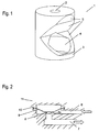
- Fig. 1 shows a valve member 1 which in the valve system according to the invention may replace the conventional cone-shaped valve body that is otherwise normally used.
- the valve member 1 has a generally cylindrical valve body with an attachment hole 2 in one of the two oppositely located, parallel end faces and a bore 4 through the other end face with a sufficiently large diameter w ( Fig. 3, 4 ) to correspond to the nominal width of the valve system.
- valve member 1 At this end the cylindrical geometry of the valve member is maintained over the full periphery at least in a partial area 3 for guidance purposes. In this way, any tilting or jamming of the valve member 1 during the sequence of movement in operation is ruled out.
- the valve member 1 includes at least one wedge-shaped recess which extends transversely to the central axis of the valve member 1 and is defined by side surfaces 5.
- the side surface 5 adjacent to the end face in which the bore 4 is located is at least partly also part of the bore 4, as a result of which an open connection is produced between this end face and the side surface adjacent to it.
- connection When the valve is in the open condition, there is a flow of medium through this connection, the connection determining the path between the inlet and the outlet.
- the valve member 1 may be manufactured either from a metallic material or from a suitable plastic material.
- Fig. 2 illustrates a typical diaphragm valve having a conventional cone-shaped valve body 8.
- Inlet 6 and outlet 7 are arranged in a valve housing 11 of the valve. In the closed condition of the valve the inlet 6 and the outlet 7 are separated by virtue of the valve body 8 sitting on a valve seat 8a in a sealing manner. A diaphragm 9 to which the valve body 8 is attached is held in the valve housing 11 by clamping means 10.
- the cone-shaped valve body 8 is replaced by the valve member 1 described above, as illustrated in Fig. 3 .
- the valve member 1 has only one wedge-shaped recess, and is connected to an actuating rod 9a.
- valve body has two identical wedge-shaped recesses located radially opposite each other. Otherwise the embodiments of Figs. 3 and 4 are similar.
- a variable flow rate valve system is shown.
- the system has a diaphragm valve similar to that shown in Fig. 2 , with a cone-shaped valve body 8 which, however, may be replaced by valve member 1 described above.
- the valve housing 11 contains a valve chamber which is divided by diaphragm 9 into a control chamber 20 and a fluid flow chamber 22 connected with inlet 6. Pilot valves 24 and 26 are associated with the diaphragm valve.
- the first pilot valve 24 is inserted in a first bypass 25 that extends between control chamber 20 and outlet 7.
- the second pilot valve 26 is inserted in a second bypass 27 that extends between control chamber 20 and inlet 6.
- the pilot valves 24 and 26 are pulsed by electric control signals received from a common control unit 30, an input of which receives a control signal U cont .
- the first pilot valve 24 is a normally closed valve
- the second pilot valve 26 is a normally open valve. Accordingly, as long as no control pulses are applied to the pilot valves, bypass 27 is open and control chamber 20 is exposed to pressure from the inlet 6, which pressure acts on diaphragm 9 to urge valve body 8 against valve seat 8a, thereby completely blocking any flow from inlet 6 to outlet 7. In case of a current supply failure, the valve system ensures blocking between inlet 6 and outlet 7. This is an important safety feature.
- control unit 30 applies control pulses to both pilot valves 24, 26 to obtain a desired flow rate in response to control signal U cont .
- the flow rate may be proportional to the value of the control signal U cont .
- the position of the valve body 8 relative to the valve seat 8a depends on the differential pressure acting on diaphragm 9 which, in turn, depends on the opening/closing conditions of bypasses 25 and 27. Otherwise expressed, it is the volume of fluid in control chamber 20 that determines the position of valve body 8 relative to valve seat 8a. When bypass 27 is open, input pressure is applied to control chamber 20, tending to move valve body 8 closer to valve seat 8a.
- control unit 30 When bypass 25 is open, pressure in control chamber 20 is allowed to be released by draining fluid to outlet 7, thereby tending to move valve body 8 away from valve seat 8a. Accordingly, any response of the resulting rate of fluid flow to the applied control signal U cont , be it proportional, continuous or in discrete steps, can be easily tailored by programming control unit 30 to issue pulse patterns to both pilot valves 24, 26 so as to achieve a target value of flow.
- Valve housing 11 is generally cylindrical, with a cover 11a. Pilot valves 24 and 26 are connected to housing 11 at integrally formed housing flanges 24a and 26a, respectively. This is an important aspect of the invention since conventional and commercially available miniature valves can be used as pilot valves.
Landscapes
- Engineering & Computer Science (AREA)
- General Engineering & Computer Science (AREA)
- Mechanical Engineering (AREA)
- Fluid-Driven Valves (AREA)
- Lift Valve (AREA)
Description
- The present invention relates to a variable flow rate valve system, preferably for liquid media.
- Variable flow rate valves have a valve member that cooperates with a valve seat to modulate a fluid flow, usually between a minimum value which may be zero and a maximum value. An actuator moves the valve member relative to the valve seat to vary the effective cross-sectional area of the flow. The actuator may be pneumatic, electro-magnetic, piezo-electric, mechanical etc. depending on a particular application and may be controlled to achieve a continuous or discontinuous characteristic of the valve responsive to a control signal. When the response is a linear function of the control signal, the valve is often referred to as a proportional valve.
-
WO 99/14522 - In
EP 1 767 841 -
US 2004/0118462 provides a control valve that reduces noise and controls flow. The control valve includes a movable plug with a plurality of tapered slots. -
GB 624 616 - The invention provides a valve member for use in a variable flow rate valve, having the features of
claim 1. - With a conventional cone-shaped valve member and in the case of a small actuating travel for realizing low rates of flow of media, high flow velocities may appear when the medium flows past on the entire periphery of the cone. This produces a suction which acts in a direction opposite to the actuation direction, which makes a sensitive closed-loop control more difficult or even impossible. The proposed valve member can reliably and precisely control desired flow rates even in the case of a small actuating travel.
- A further advantage resides in the reduction of the tendency to oscillate, which is an undesirable phenomenon frequently observed in similar systems.
- In an advantageous configuration of the valve system, the end face on the drive side of the valve member is connected to the diaphragm which seals the valve seat in the closed valve position. The diameter of the bore in the valve body advantageously corresponds to the nominal width of the valve.
- This geometry of the valve member allows the full medium flow to be able to flow off downwards and laterally even in the case of small flow rates.
- In addition, with the surface area of the valve member acted upon by the flow having the same slope and with a small actuating travel, a considerably smaller flow area is exposed to the medium than in conventional valves with a cone-shaped valve member.
- The control characteristic is adjustable by the number and the geometric configuration of the wedge-shaped incisions, the angles defining the surfaces of the at least one wedge in relation to each other and to the end faces of the valve member taking a determinative role for the characteristic.
- The invention further provides a valve system as defined in
claim 3. This valve system provides a variable flow rate valve system in which the flow rate is adjusted using the flow medium itself by creating differential pressures that determine the position of a valve member in relation to its valve seat. The valve member is actuated solely by the medium itself, e.g. water, by creating appropriate differential pressures on both sides of the diaphragm. The first and second pilot valves are preferably pulse controlled by a control unit that receives a control signal on an input. The valve system may have a proportional characteristic. Preferably, the first pilot valve is a normally closed valve and the second pilot valve is a normally open valve. This ensures that the valve is safely closed in case of a current supply failure. - An advantageous application of the inventive valve system is an armature for a shower-bath where two such valve systems would be used feeding into a common mixing chamber under control of a temperature regulator.
-
-
Figure 1 shows a three-dimensional illustration of a valve member for the valve according to the invention; -
Figure 2 shows a schematic sectional view of a section taken through part of a diaphragm valve having a conventional control cone; -
Figure 3 shows a schematic sectional view of a first embodiment of the valve member with a valve seat; -
Figure 4 shows a schematic sectional view of a second embodiment of the valve member with a valve seat; -
Figure 5 shows a schematic view of a variable flow rate valve system; and -
Figure 6 perspective view of a diaphragm valve with two pilot valves. -
Fig. 1 shows avalve member 1 which in the valve system according to the invention may replace the conventional cone-shaped valve body that is otherwise normally used. - The
valve member 1 has a generally cylindrical valve body with anattachment hole 2 in one of the two oppositely located, parallel end faces and abore 4 through the other end face with a sufficiently large diameter w (Fig. 3, 4 ) to correspond to the nominal width of the valve system. - At this end the cylindrical geometry of the valve member is maintained over the full periphery at least in a
partial area 3 for guidance purposes. In this way, any tilting or jamming of thevalve member 1 during the sequence of movement in operation is ruled out. - The
valve member 1 includes at least one wedge-shaped recess which extends transversely to the central axis of thevalve member 1 and is defined byside surfaces 5. - The
side surface 5 adjacent to the end face in which thebore 4 is located is at least partly also part of thebore 4, as a result of which an open connection is produced between this end face and the side surface adjacent to it. - When the valve is in the open condition, there is a flow of medium through this connection, the connection determining the path between the inlet and the outlet.
- The
valve member 1 may be manufactured either from a metallic material or from a suitable plastic material. -
Fig. 2 illustrates a typical diaphragm valve having a conventional cone-shaped valve body 8. -
Inlet 6 andoutlet 7 are arranged in avalve housing 11 of the valve. In the closed condition of the valve theinlet 6 and theoutlet 7 are separated by virtue of thevalve body 8 sitting on avalve seat 8a in a sealing manner. Adiaphragm 9 to which thevalve body 8 is attached is held in thevalve housing 11 by clamping means 10. - Preferably, the cone-
shaped valve body 8 is replaced by thevalve member 1 described above, as illustrated inFig. 3 . In this case, thevalve member 1 has only one wedge-shaped recess, and is connected to an actuatingrod 9a. - In the embodiment shown in
Fig. 4 , the valve body has two identical wedge-shaped recesses located radially opposite each other. Otherwise the embodiments ofFigs. 3 and 4 are similar. - In
Fig. 5 , a variable flow rate valve system is shown. The system has a diaphragm valve similar to that shown inFig. 2 , with a cone-shaped valve body 8 which, however, may be replaced byvalve member 1 described above. Thevalve housing 11 contains a valve chamber which is divided bydiaphragm 9 into acontrol chamber 20 and afluid flow chamber 22 connected withinlet 6.Pilot valves first pilot valve 24 is inserted in afirst bypass 25 that extends betweencontrol chamber 20 andoutlet 7. Thesecond pilot valve 26 is inserted in asecond bypass 27 that extends betweencontrol chamber 20 andinlet 6. - The
pilot valves common control unit 30, an input of which receives a control signal Ucont. Thefirst pilot valve 24 is a normally closed valve, and thesecond pilot valve 26 is a normally open valve. Accordingly, as long as no control pulses are applied to the pilot valves,bypass 27 is open andcontrol chamber 20 is exposed to pressure from theinlet 6, which pressure acts ondiaphragm 9 to urgevalve body 8 againstvalve seat 8a, thereby completely blocking any flow frominlet 6 tooutlet 7. In case of a current supply failure, the valve system ensures blocking betweeninlet 6 andoutlet 7. This is an important safety feature. - In operation, the
control unit 30 applies control pulses to bothpilot valves valve body 8 relative to thevalve seat 8a depends on the differential pressure acting ondiaphragm 9 which, in turn, depends on the opening/closing conditions ofbypasses control chamber 20 that determines the position ofvalve body 8 relative tovalve seat 8a. Whenbypass 27 is open, input pressure is applied to controlchamber 20, tending to movevalve body 8 closer tovalve seat 8a. Whenbypass 25 is open, pressure incontrol chamber 20 is allowed to be released by draining fluid tooutlet 7, thereby tending to movevalve body 8 away fromvalve seat 8a. Accordingly, any response of the resulting rate of fluid flow to the applied control signal Ucont, be it proportional, continuous or in discrete steps, can be easily tailored byprogramming control unit 30 to issue pulse patterns to bothpilot valves - In
Fig. 6 , one out of many possible physical implementations of the valve system is illustrated.Valve housing 11 is generally cylindrical, with acover 11a.Pilot valves housing 11 at integrally formedhousing flanges
Claims (6)
- A valve member (1) for use in a variable flow rate valve, having a generally cylindrical valve body with two opposed end faces and a peripheral wall extending between the end faces, at least one recess being formed in the peripheral wall extending inwardly, and a bore (4) extending from one of said end faces and opening into the recess, wherein the recess is wedge-shaped and extends transversely to the axis of the valve body, wherein the wedge-shaped recess is defined by surfaces (5) composed of surface sections having different angles of inclination in relation to the axis of the valve body.
- The valve member (1) according to claim 1, wherein the bore (4) has a width that corresponds to a nominal width of the valve in which the valve member (1) is used.
- A valve system comprising the valve member (1) in accordance with any of claims 1 to 2 and further comprising
a valve chamber with an inlet (6) and an outlet (7);
a diaphragm (9) dividing the valve chamber into a control chamber (20) and a flow chamber (22) connected with the inlet (6);
a valve seat (8a) arranged in the flow chamber (22) on the side of the outlet (7); a valve body (8) connected with the diaphragm (9) and cooperating with the valve seat (8a) to modulate a flow from the inlet (6) to the outlet (7) and through the flow chamber (22);
a first pilot (24) valve located in a first bypass (25) that extends between the outlet (7) and the control chamber (20);
a second pilot valve (26) located in a second bypass (27) that extends between the inlet (6) and the control chamber (20);
and a control unit (30) for controlling the first and second pilot valves (24, 26) to selectively open or close said first and second bypasses (25, 27) thereby varying the flow through the flow chamber (22) between a fully open and a fully closed condition. - The valve system according to claim 3, wherein the first and second pilot valves (24, 26) are pulse controlled by the control unit (30).
- The valve system according to claim 3 or claim 4, wherein the first pilot valve (24) is a normally closed valve and the second pilot valve (26) is a normally open valve.
- The valve system according to any of claims 3 to 5, wherein the control unit (30) controls the first and second pilot valves (24, 26) to adjust the amount of flow in response to an input signal.
Applications Claiming Priority (2)
| Application Number | Priority Date | Filing Date | Title |
|---|---|---|---|
| DE200820013969 DE202008013969U1 (en) | 2008-10-20 | 2008-10-20 | Variable flow valve |
| PCT/EP2009/007513 WO2010046090A1 (en) | 2008-10-20 | 2009-10-20 | Variable flow rate valve system |
Publications (2)
| Publication Number | Publication Date |
|---|---|
| EP2340381A1 EP2340381A1 (en) | 2011-07-06 |
| EP2340381B1 true EP2340381B1 (en) | 2012-10-03 |
Family
ID=40227441
Family Applications (1)
| Application Number | Title | Priority Date | Filing Date |
|---|---|---|---|
| EP20090744625 Not-in-force EP2340381B1 (en) | 2008-10-20 | 2009-10-20 | Variable flow rate valve system |
Country Status (5)
| Country | Link |
|---|---|
| US (1) | US8783645B2 (en) |
| EP (1) | EP2340381B1 (en) |
| JP (1) | JP5737810B2 (en) |
| DE (1) | DE202008013969U1 (en) |
| WO (1) | WO2010046090A1 (en) |
Families Citing this family (1)
| Publication number | Priority date | Publication date | Assignee | Title |
|---|---|---|---|---|
| EP2932342B1 (en) * | 2012-12-12 | 2021-05-19 | S. A. Armstrong Limited | Co-ordinated sensorless control system |
Family Cites Families (22)
| Publication number | Priority date | Publication date | Assignee | Title |
|---|---|---|---|---|
| US1998239A (en) * | 1933-04-10 | 1935-04-16 | Charles Tagliabue Mfg Co | Balanced valve |
| GB624616A (en) | 1945-01-22 | 1949-06-14 | Mason Neilan Regulator Company | Improvements in regulating valves |
| US2541176A (en) * | 1945-01-22 | 1951-02-13 | Mason Neilan Regulator Company | Control valve |
| US2664916A (en) * | 1951-08-20 | 1954-01-05 | Alvin M Conley | Hydraulic elevator descent control valve |
| DE1983869U (en) | 1968-01-19 | 1968-04-18 | Neheim Goeke & Co Metall | PRESETABLE SINGLE-SPINDLE RADIATOR REGULATING VALVE. |
| FR2125709A5 (en) | 1971-02-17 | 1972-09-29 | Bellot Roger | |
| US3791619A (en) * | 1972-01-31 | 1974-02-12 | New England Union Co | Valve construction |
| DE3520555A1 (en) * | 1985-06-07 | 1986-12-11 | H.P. + H.P. Chemie-Stellglieder GmbH, 4156 Willich | QUIET CONTROL VALVE |
| JPH0665916B2 (en) * | 1987-09-30 | 1994-08-24 | 株式会社タツノ・メカトロニクス | Flow control valve |
| ATE77683T1 (en) * | 1988-05-27 | 1992-07-15 | Koppens Automatic Fabrieken Bv | SHUT-OFF VALVE AND FLUID REGULATION/MIXING SYSTEM. |
| JPH06323464A (en) * | 1993-05-11 | 1994-11-25 | Kane Kogyo Kk | Control valve |
| JPH06346982A (en) * | 1993-06-07 | 1994-12-20 | Tgk Co Ltd | Hot water temperature regulating device for hot water supply device |
| JP2699822B2 (en) * | 1993-08-23 | 1998-01-19 | 株式会社タツノ・メカトロニクス | Flow control valve |
| US5887847A (en) | 1997-09-18 | 1999-03-30 | Automatic Switch Company | Digitally controllable flow rate valve |
| US6244561B1 (en) * | 1998-01-09 | 2001-06-12 | Hansen Technologies Corporation | Modulating expansion valve |
| JP2000097353A (en) * | 1998-09-22 | 2000-04-04 | Aisin Seiki Co Ltd | Flow control valve and fuel cell system |
| US6155531A (en) * | 1999-01-22 | 2000-12-05 | Automatic Switch Company | Proportional control value |
| JP3634733B2 (en) * | 2000-09-22 | 2005-03-30 | Smc株式会社 | Fluid pressure regulator |
| SE524115C2 (en) | 2002-04-30 | 2004-06-29 | Cci Valve Technology Ab | Valve for pressure and flow control of a gas or liquid |
| US6926249B2 (en) * | 2002-06-28 | 2005-08-09 | Invensys Building Systems, Inc. | Precision modulating globe valve |
| US20040118462A1 (en) | 2002-12-19 | 2004-06-24 | Baumann Hans D. | Control valve with low noise and enhanced flow characteristics |
| EP1767841A3 (en) | 2005-09-23 | 2009-03-25 | Robert Bosch Gmbh | Gas burner for a heating device |
-
2008
- 2008-10-20 DE DE200820013969 patent/DE202008013969U1/en not_active Expired - Lifetime
-
2009
- 2009-10-20 EP EP20090744625 patent/EP2340381B1/en not_active Not-in-force
- 2009-10-20 JP JP2011531408A patent/JP5737810B2/en not_active Expired - Fee Related
- 2009-10-20 US US13/122,978 patent/US8783645B2/en active Active
- 2009-10-20 WO PCT/EP2009/007513 patent/WO2010046090A1/en not_active Ceased
Also Published As
| Publication number | Publication date |
|---|---|
| EP2340381A1 (en) | 2011-07-06 |
| JP2012506010A (en) | 2012-03-08 |
| US20110192471A1 (en) | 2011-08-11 |
| US8783645B2 (en) | 2014-07-22 |
| JP5737810B2 (en) | 2015-06-17 |
| WO2010046090A1 (en) | 2010-04-29 |
| DE202008013969U1 (en) | 2009-01-08 |
Similar Documents
| Publication | Publication Date | Title |
|---|---|---|
| US5213303A (en) | Solenoid actuated valve with adjustable flow control | |
| US5456279A (en) | Diaphragm-type pilot valve having a self-cleaning control orifice | |
| WO2007149197A1 (en) | Bidirectional force feedback poppet valve | |
| CN101384847B (en) | Pilot operated pressure limiting valve | |
| WO2007149192A2 (en) | Poppet valve | |
| EP0765450B1 (en) | Anti hammer pilot operated valve with tortuous flow path between inlet and pilot chamber | |
| EP3513266B1 (en) | Flowrate stabilising monoblock cartridge for hydraulic valves | |
| JP5702168B2 (en) | Proportional pressure controller | |
| US10429859B2 (en) | Pressure regulator | |
| EP2868970B1 (en) | Regulating device | |
| CA3112119C (en) | Digital proportional pressure controller | |
| US8783645B2 (en) | Variable flow rate valve system | |
| WO2008057169A2 (en) | Ejector valve machine | |
| US20030052200A1 (en) | Pressure regulating valve | |
| JP5081447B2 (en) | Fluid pressure control device | |
| EP0769645A1 (en) | Proportional valve | |
| KR20090093955A (en) | Fluid level control valve | |
| EP1975758A1 (en) | Device for controlling fluid flow | |
| US20090223575A1 (en) | Ejector valve machine | |
| EP4457575A1 (en) | A pressure-independent control valve with a fluid pressure distributing sleeve, and method of distributing fluid pressure | |
| EP3447314A1 (en) | Electrically controlled hose burst valve assembly | |
| KR101709524B1 (en) | Control valve element | |
| WO2015080932A1 (en) | Valve system for bi-directional flow control | |
| WO2019187471A1 (en) | Flow rate control valve | |
| JPH0424726B2 (en) |
Legal Events
| Date | Code | Title | Description |
|---|---|---|---|
| PUAI | Public reference made under article 153(3) epc to a published international application that has entered the european phase |
Free format text: ORIGINAL CODE: 0009012 |
|
| 17P | Request for examination filed |
Effective date: 20110316 |
|
| AK | Designated contracting states |
Kind code of ref document: A1 Designated state(s): AT BE BG CH CY CZ DE DK EE ES FI FR GB GR HR HU IE IS IT LI LT LU LV MC MK MT NL NO PL PT RO SE SI SK SM TR |
|
| AX | Request for extension of the european patent |
Extension state: AL BA RS |
|
| DAX | Request for extension of the european patent (deleted) | ||
| GRAP | Despatch of communication of intention to grant a patent |
Free format text: ORIGINAL CODE: EPIDOSNIGR1 |
|
| GRAS | Grant fee paid |
Free format text: ORIGINAL CODE: EPIDOSNIGR3 |
|
| GRAA | (expected) grant |
Free format text: ORIGINAL CODE: 0009210 |
|
| AK | Designated contracting states |
Kind code of ref document: B1 Designated state(s): AT BE BG CH CY CZ DE DK EE ES FI FR GB GR HR HU IE IS IT LI LT LU LV MC MK MT NL NO PL PT RO SE SI SK SM TR |
|
| REG | Reference to a national code |
Ref country code: GB Ref legal event code: FG4D |
|
| REG | Reference to a national code |
Ref country code: AT Ref legal event code: REF Ref document number: 578131 Country of ref document: AT Kind code of ref document: T Effective date: 20121015 Ref country code: CH Ref legal event code: EP |
|
| REG | Reference to a national code |
Ref country code: IE Ref legal event code: FG4D |
|
| REG | Reference to a national code |
Ref country code: DE Ref legal event code: R096 Ref document number: 602009010199 Country of ref document: DE Effective date: 20121129 |
|
| REG | Reference to a national code |
Ref country code: AT Ref legal event code: MK05 Ref document number: 578131 Country of ref document: AT Kind code of ref document: T Effective date: 20121003 |
|
| PG25 | Lapsed in a contracting state [announced via postgrant information from national office to epo] |
Ref country code: SI Free format text: LAPSE BECAUSE OF FAILURE TO SUBMIT A TRANSLATION OF THE DESCRIPTION OR TO PAY THE FEE WITHIN THE PRESCRIBED TIME-LIMIT Effective date: 20121003 |
|
| REG | Reference to a national code |
Ref country code: NL Ref legal event code: VDEP Effective date: 20121003 |
|
| REG | Reference to a national code |
Ref country code: LT Ref legal event code: MG4D |
|
| PG25 | Lapsed in a contracting state [announced via postgrant information from national office to epo] |
Ref country code: SE Free format text: LAPSE BECAUSE OF FAILURE TO SUBMIT A TRANSLATION OF THE DESCRIPTION OR TO PAY THE FEE WITHIN THE PRESCRIBED TIME-LIMIT Effective date: 20121003 Ref country code: NO Free format text: LAPSE BECAUSE OF FAILURE TO SUBMIT A TRANSLATION OF THE DESCRIPTION OR TO PAY THE FEE WITHIN THE PRESCRIBED TIME-LIMIT Effective date: 20130103 Ref country code: IS Free format text: LAPSE BECAUSE OF FAILURE TO SUBMIT A TRANSLATION OF THE DESCRIPTION OR TO PAY THE FEE WITHIN THE PRESCRIBED TIME-LIMIT Effective date: 20130203 Ref country code: LT Free format text: LAPSE BECAUSE OF FAILURE TO SUBMIT A TRANSLATION OF THE DESCRIPTION OR TO PAY THE FEE WITHIN THE PRESCRIBED TIME-LIMIT Effective date: 20121003 Ref country code: NL Free format text: LAPSE BECAUSE OF FAILURE TO SUBMIT A TRANSLATION OF THE DESCRIPTION OR TO PAY THE FEE WITHIN THE PRESCRIBED TIME-LIMIT Effective date: 20121003 Ref country code: HR Free format text: LAPSE BECAUSE OF FAILURE TO SUBMIT A TRANSLATION OF THE DESCRIPTION OR TO PAY THE FEE WITHIN THE PRESCRIBED TIME-LIMIT Effective date: 20121003 Ref country code: FI Free format text: LAPSE BECAUSE OF FAILURE TO SUBMIT A TRANSLATION OF THE DESCRIPTION OR TO PAY THE FEE WITHIN THE PRESCRIBED TIME-LIMIT Effective date: 20121003 |
|
| PG25 | Lapsed in a contracting state [announced via postgrant information from national office to epo] |
Ref country code: PL Free format text: LAPSE BECAUSE OF FAILURE TO SUBMIT A TRANSLATION OF THE DESCRIPTION OR TO PAY THE FEE WITHIN THE PRESCRIBED TIME-LIMIT Effective date: 20121003 Ref country code: LV Free format text: LAPSE BECAUSE OF FAILURE TO SUBMIT A TRANSLATION OF THE DESCRIPTION OR TO PAY THE FEE WITHIN THE PRESCRIBED TIME-LIMIT Effective date: 20121003 Ref country code: MC Free format text: LAPSE BECAUSE OF NON-PAYMENT OF DUE FEES Effective date: 20121031 Ref country code: GR Free format text: LAPSE BECAUSE OF FAILURE TO SUBMIT A TRANSLATION OF THE DESCRIPTION OR TO PAY THE FEE WITHIN THE PRESCRIBED TIME-LIMIT Effective date: 20130104 Ref country code: BE Free format text: LAPSE BECAUSE OF FAILURE TO SUBMIT A TRANSLATION OF THE DESCRIPTION OR TO PAY THE FEE WITHIN THE PRESCRIBED TIME-LIMIT Effective date: 20121003 Ref country code: PT Free format text: LAPSE BECAUSE OF FAILURE TO SUBMIT A TRANSLATION OF THE DESCRIPTION OR TO PAY THE FEE WITHIN THE PRESCRIBED TIME-LIMIT Effective date: 20130204 |
|
| PG25 | Lapsed in a contracting state [announced via postgrant information from national office to epo] |
Ref country code: AT Free format text: LAPSE BECAUSE OF FAILURE TO SUBMIT A TRANSLATION OF THE DESCRIPTION OR TO PAY THE FEE WITHIN THE PRESCRIBED TIME-LIMIT Effective date: 20121003 |
|
| REG | Reference to a national code |
Ref country code: IE Ref legal event code: MM4A |
|
| PG25 | Lapsed in a contracting state [announced via postgrant information from national office to epo] |
Ref country code: SK Free format text: LAPSE BECAUSE OF FAILURE TO SUBMIT A TRANSLATION OF THE DESCRIPTION OR TO PAY THE FEE WITHIN THE PRESCRIBED TIME-LIMIT Effective date: 20121003 Ref country code: DK Free format text: LAPSE BECAUSE OF FAILURE TO SUBMIT A TRANSLATION OF THE DESCRIPTION OR TO PAY THE FEE WITHIN THE PRESCRIBED TIME-LIMIT Effective date: 20121003 Ref country code: EE Free format text: LAPSE BECAUSE OF FAILURE TO SUBMIT A TRANSLATION OF THE DESCRIPTION OR TO PAY THE FEE WITHIN THE PRESCRIBED TIME-LIMIT Effective date: 20121003 Ref country code: CZ Free format text: LAPSE BECAUSE OF FAILURE TO SUBMIT A TRANSLATION OF THE DESCRIPTION OR TO PAY THE FEE WITHIN THE PRESCRIBED TIME-LIMIT Effective date: 20121003 Ref country code: BG Free format text: LAPSE BECAUSE OF FAILURE TO SUBMIT A TRANSLATION OF THE DESCRIPTION OR TO PAY THE FEE WITHIN THE PRESCRIBED TIME-LIMIT Effective date: 20130103 Ref country code: IE Free format text: LAPSE BECAUSE OF NON-PAYMENT OF DUE FEES Effective date: 20121020 |
|
| PLBE | No opposition filed within time limit |
Free format text: ORIGINAL CODE: 0009261 |
|
| STAA | Information on the status of an ep patent application or granted ep patent |
Free format text: STATUS: NO OPPOSITION FILED WITHIN TIME LIMIT |
|
| PG25 | Lapsed in a contracting state [announced via postgrant information from national office to epo] |
Ref country code: RO Free format text: LAPSE BECAUSE OF FAILURE TO SUBMIT A TRANSLATION OF THE DESCRIPTION OR TO PAY THE FEE WITHIN THE PRESCRIBED TIME-LIMIT Effective date: 20121003 Ref country code: IT Free format text: LAPSE BECAUSE OF FAILURE TO SUBMIT A TRANSLATION OF THE DESCRIPTION OR TO PAY THE FEE WITHIN THE PRESCRIBED TIME-LIMIT Effective date: 20121003 |
|
| 26N | No opposition filed |
Effective date: 20130704 |
|
| PG25 | Lapsed in a contracting state [announced via postgrant information from national office to epo] |
Ref country code: ES Free format text: LAPSE BECAUSE OF FAILURE TO SUBMIT A TRANSLATION OF THE DESCRIPTION OR TO PAY THE FEE WITHIN THE PRESCRIBED TIME-LIMIT Effective date: 20130114 |
|
| REG | Reference to a national code |
Ref country code: DE Ref legal event code: R097 Ref document number: 602009010199 Country of ref document: DE Effective date: 20130704 |
|
| PG25 | Lapsed in a contracting state [announced via postgrant information from national office to epo] |
Ref country code: MT Free format text: LAPSE BECAUSE OF FAILURE TO SUBMIT A TRANSLATION OF THE DESCRIPTION OR TO PAY THE FEE WITHIN THE PRESCRIBED TIME-LIMIT Effective date: 20121003 Ref country code: CY Free format text: LAPSE BECAUSE OF FAILURE TO SUBMIT A TRANSLATION OF THE DESCRIPTION OR TO PAY THE FEE WITHIN THE PRESCRIBED TIME-LIMIT Effective date: 20121003 |
|
| PG25 | Lapsed in a contracting state [announced via postgrant information from national office to epo] |
Ref country code: TR Free format text: LAPSE BECAUSE OF FAILURE TO SUBMIT A TRANSLATION OF THE DESCRIPTION OR TO PAY THE FEE WITHIN THE PRESCRIBED TIME-LIMIT Effective date: 20121003 |
|
| PG25 | Lapsed in a contracting state [announced via postgrant information from national office to epo] |
Ref country code: SM Free format text: LAPSE BECAUSE OF FAILURE TO SUBMIT A TRANSLATION OF THE DESCRIPTION OR TO PAY THE FEE WITHIN THE PRESCRIBED TIME-LIMIT Effective date: 20121003 Ref country code: LU Free format text: LAPSE BECAUSE OF NON-PAYMENT OF DUE FEES Effective date: 20121020 |
|
| REG | Reference to a national code |
Ref country code: CH Ref legal event code: PL |
|
| GBPC | Gb: european patent ceased through non-payment of renewal fee |
Effective date: 20131020 |
|
| PG25 | Lapsed in a contracting state [announced via postgrant information from national office to epo] |
Ref country code: GB Free format text: LAPSE BECAUSE OF NON-PAYMENT OF DUE FEES Effective date: 20131020 Ref country code: LI Free format text: LAPSE BECAUSE OF NON-PAYMENT OF DUE FEES Effective date: 20131031 Ref country code: HU Free format text: LAPSE BECAUSE OF FAILURE TO SUBMIT A TRANSLATION OF THE DESCRIPTION OR TO PAY THE FEE WITHIN THE PRESCRIBED TIME-LIMIT Effective date: 20091020 Ref country code: CH Free format text: LAPSE BECAUSE OF NON-PAYMENT OF DUE FEES Effective date: 20131031 |
|
| PG25 | Lapsed in a contracting state [announced via postgrant information from national office to epo] |
Ref country code: MK Free format text: LAPSE BECAUSE OF FAILURE TO SUBMIT A TRANSLATION OF THE DESCRIPTION OR TO PAY THE FEE WITHIN THE PRESCRIBED TIME-LIMIT Effective date: 20121003 |
|
| REG | Reference to a national code |
Ref country code: FR Ref legal event code: PLFP Year of fee payment: 7 |
|
| REG | Reference to a national code |
Ref country code: FR Ref legal event code: PLFP Year of fee payment: 8 |
|
| REG | Reference to a national code |
Ref country code: FR Ref legal event code: PLFP Year of fee payment: 9 |
|
| REG | Reference to a national code |
Ref country code: FR Ref legal event code: PLFP Year of fee payment: 10 |
|
| P01 | Opt-out of the competence of the unified patent court (upc) registered |
Effective date: 20230523 |
|
| PGFP | Annual fee paid to national office [announced via postgrant information from national office to epo] |
Ref country code: FR Payment date: 20231024 Year of fee payment: 15 Ref country code: DE Payment date: 20231026 Year of fee payment: 15 |
|
| REG | Reference to a national code |
Ref country code: DE Ref legal event code: R119 Ref document number: 602009010199 Country of ref document: DE |
|
| PG25 | Lapsed in a contracting state [announced via postgrant information from national office to epo] |
Ref country code: DE Free format text: LAPSE BECAUSE OF NON-PAYMENT OF DUE FEES Effective date: 20250501 |
|
| PG25 | Lapsed in a contracting state [announced via postgrant information from national office to epo] |
Ref country code: FR Free format text: LAPSE BECAUSE OF NON-PAYMENT OF DUE FEES Effective date: 20241031 |