EP2339748A1 - Resonator - Google Patents
Resonator Download PDFInfo
- Publication number
- EP2339748A1 EP2339748A1 EP09252287A EP09252287A EP2339748A1 EP 2339748 A1 EP2339748 A1 EP 2339748A1 EP 09252287 A EP09252287 A EP 09252287A EP 09252287 A EP09252287 A EP 09252287A EP 2339748 A1 EP2339748 A1 EP 2339748A1
- Authority
- EP
- European Patent Office
- Prior art keywords
- resonator
- spring constant
- cte
- support
- temperature
- Prior art date
- Legal status (The legal status is an assumption and is not a legal conclusion. Google has not performed a legal analysis and makes no representation as to the accuracy of the status listed.)
- Granted
Links
- 239000000463 material Substances 0.000 claims abstract description 42
- 230000010355 oscillation Effects 0.000 claims abstract description 19
- 238000000034 method Methods 0.000 claims description 18
- XUIMIQQOPSSXEZ-UHFFFAOYSA-N Silicon Chemical compound [Si] XUIMIQQOPSSXEZ-UHFFFAOYSA-N 0.000 claims description 17
- 229910052710 silicon Inorganic materials 0.000 claims description 17
- 239000010703 silicon Substances 0.000 claims description 17
- 239000000758 substrate Substances 0.000 claims description 13
- 229910003217 Ni3Si Inorganic materials 0.000 claims description 9
- 239000011797 cavity material Substances 0.000 description 18
- 230000000694 effects Effects 0.000 description 6
- VYPSYNLAJGMNEJ-UHFFFAOYSA-N silicon dioxide Inorganic materials O=[Si]=O VYPSYNLAJGMNEJ-UHFFFAOYSA-N 0.000 description 4
- PXHVJJICTQNCMI-UHFFFAOYSA-N Nickel Chemical compound [Ni] PXHVJJICTQNCMI-UHFFFAOYSA-N 0.000 description 3
- 229910021421 monocrystalline silicon Inorganic materials 0.000 description 3
- 235000012239 silicon dioxide Nutrition 0.000 description 3
- 239000011248 coating agent Substances 0.000 description 2
- 238000000576 coating method Methods 0.000 description 2
- 230000008602 contraction Effects 0.000 description 2
- 230000001419 dependent effect Effects 0.000 description 2
- 238000000151 deposition Methods 0.000 description 2
- 239000010453 quartz Substances 0.000 description 2
- 230000015572 biosynthetic process Effects 0.000 description 1
- 238000009529 body temperature measurement Methods 0.000 description 1
- 230000006835 compression Effects 0.000 description 1
- 238000007906 compression Methods 0.000 description 1
- 230000008021 deposition Effects 0.000 description 1
- 238000005530 etching Methods 0.000 description 1
- 238000001914 filtration Methods 0.000 description 1
- 238000010438 heat treatment Methods 0.000 description 1
- 230000003116 impacting effect Effects 0.000 description 1
- 238000002955 isolation Methods 0.000 description 1
- 239000002184 metal Substances 0.000 description 1
- 229910052751 metal Inorganic materials 0.000 description 1
- 229910052759 nickel Inorganic materials 0.000 description 1
- 230000003647 oxidation Effects 0.000 description 1
- 238000007254 oxidation reaction Methods 0.000 description 1
- 230000002040 relaxant effect Effects 0.000 description 1
- 229910021332 silicide Inorganic materials 0.000 description 1
- 239000000377 silicon dioxide Substances 0.000 description 1
- 230000003068 static effect Effects 0.000 description 1
Images


Classifications
-
- H—ELECTRICITY
- H03—ELECTRONIC CIRCUITRY
- H03H—IMPEDANCE NETWORKS, e.g. RESONANT CIRCUITS; RESONATORS
- H03H9/00—Networks comprising electromechanical or electro-acoustic elements; Electromechanical resonators
- H03H9/02—Details
- H03H9/02244—Details of microelectro-mechanical resonators
- H03H9/02433—Means for compensation or elimination of undesired effects
- H03H9/02448—Means for compensation or elimination of undesired effects of temperature influence
-
- B—PERFORMING OPERATIONS; TRANSPORTING
- B81—MICROSTRUCTURAL TECHNOLOGY
- B81B—MICROSTRUCTURAL DEVICES OR SYSTEMS, e.g. MICROMECHANICAL DEVICES
- B81B3/00—Devices comprising flexible or deformable elements, e.g. comprising elastic tongues or membranes
- B81B3/0064—Constitution or structural means for improving or controlling the physical properties of a device
- B81B3/0067—Mechanical properties
- B81B3/0072—For controlling internal stress or strain in moving or flexible elements, e.g. stress compensating layers
-
- H—ELECTRICITY
- H03—ELECTRONIC CIRCUITRY
- H03H—IMPEDANCE NETWORKS, e.g. RESONANT CIRCUITS; RESONATORS
- H03H9/00—Networks comprising electromechanical or electro-acoustic elements; Electromechanical resonators
- H03H9/24—Constructional features of resonators of material which is not piezoelectric, electrostrictive, or magnetostrictive
- H03H9/2405—Constructional features of resonators of material which is not piezoelectric, electrostrictive, or magnetostrictive of microelectro-mechanical resonators
- H03H9/2447—Beam resonators
-
- B—PERFORMING OPERATIONS; TRANSPORTING
- B81—MICROSTRUCTURAL TECHNOLOGY
- B81B—MICROSTRUCTURAL DEVICES OR SYSTEMS, e.g. MICROMECHANICAL DEVICES
- B81B2201/00—Specific applications of microelectromechanical systems
- B81B2201/02—Sensors
- B81B2201/0271—Resonators; ultrasonic resonators
-
- B—PERFORMING OPERATIONS; TRANSPORTING
- B81—MICROSTRUCTURAL TECHNOLOGY
- B81B—MICROSTRUCTURAL DEVICES OR SYSTEMS, e.g. MICROMECHANICAL DEVICES
- B81B2203/00—Basic microelectromechanical structures
- B81B2203/01—Suspended structures, i.e. structures allowing a movement
- B81B2203/0118—Cantilevers
-
- Y—GENERAL TAGGING OF NEW TECHNOLOGICAL DEVELOPMENTS; GENERAL TAGGING OF CROSS-SECTIONAL TECHNOLOGIES SPANNING OVER SEVERAL SECTIONS OF THE IPC; TECHNICAL SUBJECTS COVERED BY FORMER USPC CROSS-REFERENCE ART COLLECTIONS [XRACs] AND DIGESTS
- Y10—TECHNICAL SUBJECTS COVERED BY FORMER USPC
- Y10T—TECHNICAL SUBJECTS COVERED BY FORMER US CLASSIFICATION
- Y10T29/00—Metal working
- Y10T29/49—Method of mechanical manufacture
- Y10T29/49002—Electrical device making
Definitions
- This invention relates to a resonator structure, particularly to a MEMS (Micromechanical System) resonator.
- MEMS Micromechanical System
- Such structures may be used instead of quartz resonators as frequency references for many applications due to their low cost and reduced size compared to quartz.
- MEMS resonators are typically formed from silicon, it is possible to readily integrate MEMS resonators with other control circuitry within one package.
- micromechanical systems are devices formed from small components configured on a substrate for example, a silicon substrate.
- a MEMS resonator comprises a beam (or spring) structure supported by one or more supports which supports are connected to, or formed integrally with the substrate.
- MEMS resonators may be used, for example, as parts of clocks or as signal filtering circuits.
- a problem with MEMS resonators is that the oscillation frequency of the resonator varies with the ambient temperature and with the materials and processes used to form the resonator.
- the main cause of the temperature dependence of the resonance frequency is the temperature coefficient of the elastic (Young's) modulus.
- a MEMS resonator will be formed from a material having a negative temperature coefficient of the elastic modulus of that material. This means that the spring constant of the resonator will be reduced at high temperatures which in turn results in a reduced oscillation frequency.
- Known techniques for attempting to correct the temperature dependence of the oscillation frequency maybe classified as either active or passive temperature compensation techniques.
- Known active temperature compensation techniques include temperature measurement followed by bias voltage correction, phase-locked loop (PPL) control feedback, and the heating of resonator springs to a predetermined temperature.
- PPL phase-locked loop
- a problem with such active temperature compensation techniques is that they suffer from large power dissipation. Additionally in the case of phase-locked loop control feedback, there is an unacceptable phase noise produced.
- a known passive compensation technique involves depositing a coating of one or more layers onto the beam of a MEMS resonator.
- Each of the one or more layers has a different temperature coefficient of the respective elastic modulus to that of the beam.
- the beam is formed from a material having a negative temperature coefficient of the elastic modulus
- the one or more materials which are deposited or coated onto the beam are chosen because they each have a positive temperature coefficient of the respective elastic modulus. This means that any expansion or contraction of the beam may be compensated for by contraction or expansion of the one or more other materials.
- a problem with these known passive techniques is that the formation processes such as deposition and oxidation that are used to coat the beam with one or more materials are not well enough controlled to deliver the required accuracy of thickness of coating.
- the spring constant is extremely sensitive to the width of the beam which also makes it very difficult to obtain accuracy.
- a resonator having an effective spring constant and comprising a beam having a beam spring constant adapted to resonate in an oscillation direction, and extending at a non-zero angle ( ⁇ ) to the oscillation direction, wherein the resonator has a predetermined geometry and is formed from one or more materials, the or each material having a coefficient of thermal expansion (CTE), the CTE of the or each material together with the predetermined geometry of the resonator causing ⁇ to vary with temperature, such that the temperature dependence of the beam spring constant is compensated for, resulting in the effective spring constant of the resonator remaining substantially constant within an operating temperature range.
- CTE coefficient of thermal expansion
- the effective spring constant of a resonator remains substantially constant within an operating temperature range of the resonator.
- the resonant frequency of the resonator depends on the extent to which the oscillator (the beam) will stretch when a particular force is applied to it, or by it (see equation 2 below).
- the extent that an oscillator will stretch is directly dependent on the spring constant of the oscillator.
- the resonant frequency of an oscillator is a function of the extent to which an oscillator will stretch. This means that there is a relationship between the resonant frequency of the resonator and the spring constant of the resonator.
- the resonant frequency (F) is proportional to the square root of the spring constant (k) divided by the mass (m) of the resonator (F ⁇ (k/m).
- the temperature dependence of the spring constant (and therefore the elastic modulus) of the material forming the beam of the resonator is compensated for, by forming the beam and other components of the resonator from a material or materials having thermal expansion coefficients that cause the geometry of the resonator to change with temperature to an extent that substantially compensates for the change in k with temperature such that the resonator frequency is substantially independent of the temperature.
- the invention is based on the inventor's realisation that there is a direct correlation between the effective spring constant of a resonator as a whole, in the oscillation direction, and the spring constant of the beam.
- the resonator may comprise a micromechanical resonator in which at least parts of the resonator such as the beam are formed from silicon.
- CMOS fabricating techniques it is possible to use CMOS fabricating techniques to incorporate the resonator into integrated circuit for example.
- parts of the resonator may be formed from a silicon substrate.
- the parts of the resonator may be integrally formed in a silicon substrate.
- the resonator may further comprise a support supporting the beam.
- the resonator may further comprise a cavity defined below the beam. The cavity enables the beam to flex into the cavity when resonating.
- the support, and cavity of the resonator enable the beam to flex freely in a resonance mode.
- the resonator according to the invention may comprise more than one beam.
- the spring constant of each beam will be compensated for resulting in the effective spring constant of the resonator remaining substantially constant within the operating temperature range.
- a resonator according to embodiments of the invention may comprise more than one support.
- the resonator may also comprise more than cavity.
- the resonator may further comprise a mass attached to, or formed integrally with the beam.
- the resonator may comprise more than one mass.
- the support is distinct from the beam that it supports because it does not move in response to any vibration motion of the mass.
- a method for tuning a resonator comprising a beam having a beam spring constant adapted to resonate in an oscillation direction, and extending at a non-zero angle ( ⁇ ) to the oscillation direction, wherein the resonator has a predetermined geometry and is formed from one or more materials, the or each material having a coefficient of thermal expansion (CTE), the CTE of the or each material together with the predetermined geometry of the resonator causing ⁇ to vary with temperature, such that the temperature dependence of the beam spring constant is compensated for, the method comprising the step of altering the geometry of the resonator whereby the effective spring constant of the resonator will remain substantially constant within an operating temperature range.
- CTE coefficient of thermal expansion
- the method may comprise the step of forming the resonator from a silicon substrate.
- the resonator may comprise one or more supports supporting the beam, and the step of altering the geometry of the resonator may comprise the step of adjusting the dimensions of the support, for example, the lateral dimensions of the support.
- the magnitude of ⁇ , the angle of the beam relative to the oscillation direction will depend on the geometry of the resonator, and the material or materials from which the resonator has been manufactured.
- the magnitude of ⁇ may fall within the range 10° to 60°, preferably 10° to 45°, more preferably 10° to 30°.
- the beam and the support are both formed from pure silicon.
- the support may have any particular length but in one embodiment the support length may be 10 times the length of the beam and ⁇ may be substantially 28°.
- the support is formed from Ni 3 Si and has a length that is 10 times the length of the beam and ⁇ is substantially 60°.
- the spring constant of the beam will vary with temperature
- a change in dimensions of the beam caused by a change in the operating temperature can be tuned so that the effective spring constant k z remains constant within the temperature range.
- the change in dimensions of the beam caused by the change in temperature can be tuned so that the change in ⁇ caused by the expansion or contract of the beam compensates for the change in the spring constant of the particular component so that the effective spring constant of the resonator of a whole remains constant as the temperature varies.
- a MEMS resonator according to an embodiment of the invention is designated by the reference numeral 2.
- the resonator comprises four beams 4.
- a first pair of beams 4a forms a first spring 6a
- a second pair of beams 4b forms a second spring 6b.
- the beams 4a, 4b are supported by supports 8.
- the resonator further comprises masses 12 attached to, or formed integrally with one or more beams.
- the resonator further comprises a cavity 10 (not shown in Figure 1 ) and a mass 12.
- the masses 12 are attached only to the beams 4, and are otherwise freestanding.
- the resonator is formed from a suitable material such as monocrystalline silicon, silicon dioxide in combination with Si, etc. in a known manner by etching a substrate such that the beam and spring are suspended over the substrate and are supported by the support beam 8 over a cavity.
- a suitable material such as monocrystalline silicon, silicon dioxide in combination with Si, etc.
- each beam 4 is arranged to lie at an angle of ⁇ to the oscillation direction which is indicated by the arrow z.
- the materials used to form the components of the resonator 2 each have a negative temperature coefficient of the elastic modulus. This means that the spring constant of a particular component is reduced at higher temperatures resulting in a lower resonant frequency of oscillation.
- ⁇ B is the thermal expansion coefficient of the beam
- W is the width of the cavity
- L s is the length of the beam 4
- L B is the length of the support 8.
- CTE w is the coefficient of thermal expansion of the substrate
- CTE s is the coefficient of thermal expansion of the support
- CTE b is the coefficient of thermal expansion of the beam.
- the coefficient of thermal expansion of the beam will be 2.5 e-6 deg -1
- the thermal expansion coefficient to the beam ⁇ B will be 2 e-4 deg -1 .
- ⁇ B CTE S 2 ⁇ W - L s ⁇ L s W - L s 2 - L B 2
- CTE s is the coefficient of thermal expansion of the support material.
- the dependence of this ratio is a function of ⁇ is shown in Figure 3 for various support lengths which are expressed in units of beam length.
- ⁇ B /CTE s for a support beam made from pure silicon and also for a support beam made from Ni 3 Si.
- the coefficient of thermal expansion of Ni 3 Si is 15 e-6 K -1 .
- ⁇ is required to be approximately 28°.
- ⁇ is required to be 60° due to the larger CTE of Ni 3 Si.
- the support beam may be formed from Ni 3 Si by reacting silicon with nickel (Ni) in a controlled manner.
- Cavity expansion enhances rather than cancels ⁇ B .
- a resonator formed from pure silicon there is no geometrical change and thus cavity expansion perfectly cancels the effect of the beam and support expansion.
- the CTE of the cavity is defined by the substrate material which is usually monocrystalline silicon. This means that if the CTE of the support is adjusted, substantial tuning of the compensation effect shown in Figure 3 can be achieved using well controlled process steps and without impacting on the mechanical properties of the materials in critical regions.
- An important feature of the present invention is that it is possible to tune the layout and material properties of the support in order to substantially perfectly compensate even if other expansion effects are included.
- the width, or the length, of the support may be altered in order to tune the resonator such that the effective spring constant of the resonator will remain substantially constant within a desired operating temperature range of the resonator.
- the resonator 20 comprises supports 80 that support a beam 6.
- the supports 80 are formed from Ni 3 Si.
- the configuration of resonator 20 is similar to that of resonator 2 illustrated in Figure 1 .
- Figure 6 shows the cavity 82 located beneath the beam 6.
Landscapes
- Physics & Mathematics (AREA)
- Acoustics & Sound (AREA)
- Engineering & Computer Science (AREA)
- Mechanical Engineering (AREA)
- Computer Hardware Design (AREA)
- Microelectronics & Electronic Packaging (AREA)
- Micromachines (AREA)
- Piezo-Electric Or Mechanical Vibrators, Or Delay Or Filter Circuits (AREA)
Abstract
Description
- This invention relates to a resonator structure, particularly to a MEMS (Micromechanical System) resonator. Such structures may be used instead of quartz resonators as frequency references for many applications due to their low cost and reduced size compared to quartz. In addition, since MEMS resonators are typically formed from silicon, it is possible to readily integrate MEMS resonators with other control circuitry within one package.
- As is well known in the art, micromechanical systems are devices formed from small components configured on a substrate for example, a silicon substrate.
- A MEMS resonator comprises a beam (or spring) structure supported by one or more supports which supports are connected to, or formed integrally with the substrate. MEMS resonators may be used, for example, as parts of clocks or as signal filtering circuits.
- A problem with MEMS resonators is that the oscillation frequency of the resonator varies with the ambient temperature and with the materials and processes used to form the resonator.
- The main cause of the temperature dependence of the resonance frequency is the temperature coefficient of the elastic (Young's) modulus. Usually a MEMS resonator will be formed from a material having a negative temperature coefficient of the elastic modulus of that material. This means that the spring constant of the resonator will be reduced at high temperatures which in turn results in a reduced oscillation frequency.
- Known techniques for attempting to correct the temperature dependence of the oscillation frequency maybe classified as either active or passive temperature compensation techniques.
- Known active temperature compensation techniques include temperature measurement followed by bias voltage correction, phase-locked loop (PPL) control feedback, and the heating of resonator springs to a predetermined temperature. A problem with such active temperature compensation techniques is that they suffer from large power dissipation. Additionally in the case of phase-locked loop control feedback, there is an unacceptable phase noise produced.
- A known passive compensation technique involves depositing a coating of one or more layers onto the beam of a MEMS resonator. Each of the one or more layers has a different temperature coefficient of the respective elastic modulus to that of the beam. When, as is usually the case, the beam is formed from a material having a negative temperature coefficient of the elastic modulus, then the one or more materials which are deposited or coated onto the beam are chosen because they each have a positive temperature coefficient of the respective elastic modulus. This means that any expansion or contraction of the beam may be compensated for by contraction or expansion of the one or more other materials.
- International patent application No.
WO 2004/095696 describes a flexural resonator beam in which different materials are used to compensate for the coefficient of thermal expansion. The resonator disclosed inWO 2004/095696 relies on tensional forces in order to compensate for the temperature dependence of the resonant frequency. - A problem with these known passive techniques is that the formation processes such as deposition and oxidation that are used to coat the beam with one or more materials are not well enough controlled to deliver the required accuracy of thickness of coating. In addition, the spring constant is extremely sensitive to the width of the beam which also makes it very difficult to obtain accuracy.
- According to a first aspect of the present invention there is provided a resonator having an effective spring constant and comprising a beam having a beam spring constant adapted to resonate in an oscillation direction, and extending at a non-zero angle (θ) to the oscillation direction, wherein the resonator has a predetermined geometry and is formed from one or more materials, the or each material having a coefficient of thermal expansion (CTE), the CTE of the or each material together with the predetermined geometry of the resonator causing θ to vary with temperature, such that the temperature dependence of the beam spring constant is compensated for, resulting in the effective spring constant of the resonator remaining substantially constant within an operating temperature range.
- By means of the present invention the effective spring constant of a resonator remains substantially constant within an operating temperature range of the resonator. The resonant frequency of the resonator depends on the extent to which the oscillator (the beam) will stretch when a particular force is applied to it, or by it (see equation 2 below). The extent that an oscillator will stretch is directly dependent on the spring constant of the oscillator. In turn, the resonant frequency of an oscillator is a function of the extent to which an oscillator will stretch. This means that there is a relationship between the resonant frequency of the resonator and the spring constant of the resonator. More particularly, the resonant frequency (F) is proportional to the square root of the spring constant (k) divided by the mass (m) of the resonator (F∼√(k/m). Thus by ensuring that the effective spring constant of the resonator remains substantially constant, the resonant frequency of the resonator will be substantially independent of temperature within the operating temperature of the resonator.
- By means of the present invention, the temperature dependence of the spring constant (and therefore the elastic modulus) of the material forming the beam of the resonator is compensated for, by forming the beam and other components of the resonator from a material or materials having thermal expansion coefficients that cause the geometry of the resonator to change with temperature to an extent that substantially compensates for the change in k with temperature such that the resonator frequency is substantially independent of the temperature.
- This is achieved without having to coat the beam with layers of material that have a temperature coefficient of Young's modulus of opposite sign to that of the material from which the beam is formed, or without having to introduce a static strain into the beam.
- The invention is based on the inventor's realisation that there is a direct correlation between the effective spring constant of a resonator as a whole, in the oscillation direction, and the spring constant of the beam.
- The resonator may comprise a micromechanical resonator in which at least parts of the resonator such as the beam are formed from silicon. By forming the resonator at least in part from silicon, it is possible to use CMOS fabricating techniques to incorporate the resonator into integrated circuit for example.
- In such embodiments, parts of the resonator may be formed from a silicon substrate. In particular, the parts of the resonator may be integrally formed in a silicon substrate.
- The resonator may further comprise a support supporting the beam. The resonator may further comprise a cavity defined below the beam. The cavity enables the beam to flex into the cavity when resonating. The support, and cavity of the resonator enable the beam to flex freely in a resonance mode.
- The resonator according to the invention may comprise more than one beam. In such an embodiment, the spring constant of each beam will be compensated for resulting in the effective spring constant of the resonator remaining substantially constant within the operating temperature range.
- A resonator according to embodiments of the invention may comprise more than one support. The resonator may also comprise more than cavity.
- The resonator may further comprise a mass attached to, or formed integrally with the beam. The resonator may comprise more than one mass.
- The support is distinct from the beam that it supports because it does not move in response to any vibration motion of the mass.
- The term "below" is not meant to imply any particular orientation of the resonator.
- According to a second aspect of the present invention there is provided a method for tuning a resonator, the resonator having an effective spring constant and comprising a beam having a beam spring constant adapted to resonate in an oscillation direction, and extending at a non-zero angle (θ) to the oscillation direction, wherein the resonator has a predetermined geometry and is formed from one or more materials, the or each material having a coefficient of thermal expansion (CTE), the CTE of the or each material together with the predetermined geometry of the resonator causing θ to vary with temperature, such that the temperature dependence of the beam spring constant is compensated for, the method comprising the step of altering the geometry of the resonator whereby the effective spring constant of the resonator will remain substantially constant within an operating temperature range.
- The method may comprise the step of forming the resonator from a silicon substrate.
- The resonator may comprise one or more supports supporting the beam, and the step of altering the geometry of the resonator may comprise the step of adjusting the dimensions of the support, for example, the lateral dimensions of the support.
- The magnitude of θ, the angle of the beam relative to the oscillation direction will depend on the geometry of the resonator, and the material or materials from which the resonator has been manufactured. The magnitude of θ may fall within the
range 10° to 60°, preferably 10° to 45°, more preferably 10° to 30°. In one embodiment of the invention, the beam and the support are both formed from pure silicon. The support may have any particular length but in one embodiment the support length may be 10 times the length of the beam and θ may be substantially 28°. - In another embodiment of the invention, the support is formed from Ni3Si and has a length that is 10 times the length of the beam and θ is substantially 60°.
- For a simple spring-mass resonator geometry, the effective spring constant of the resonator in the oscillation direction (the z direction) is denoted by the symbol kz, and the spring constant of the beam is denoted by kB.

- This relationship assumes that the torsional forces are negligible compared to the forces due to linear expansion or compression of the beam.
- Since the spring constant of the beam will vary with temperature, by forming the resonator, from a material or materials having an appropriate coefficient of thermal expansion (CTE), a change in dimensions of the beam caused by a change in the operating temperature can be tuned so that the effective spring constant kz remains constant within the temperature range. In other words, by choosing an appropriate geometry and appropriate materials, the change in dimensions of the beam caused by the change in temperature can be tuned so that the change in θ caused by the expansion or contract of the beam compensates for the change in the spring constant of the particular component so that the effective spring constant of the resonator of a whole remains constant as the temperature varies.
- By means of the present invention therefore it is possible to achieve a substantially constant effective spring constant for a resonator within a particular temperature range without having to introduce strain to the beam of the resonator in order to adjust the spring constant.
- The invention will now be further described by way of example only with reference to the accompanying drawings in which:
-
Figure 1 is a schematic plan view of a micromechanical resonator according to the present invention; -
Figure 2 is a graphical representation showing the magnitude of the angle of the beam (θ) of the resonator ofFigure 1 relative to the direction of oscillation that is required to maintain a temperature independent spring constant kz, as a function of the ratio of the temperature coefficient of the elastic modulus to CTEb, with other expansion effects neglected; -
Figure 3 is a graphical representation showing the magnitude of the angle θ that is required to maintain a temperature independent spring constant kz as a function of the ratio of the temperature coefficient of the elastic modulus to CTEs with other expansion effects being neglected, and the support length; -
Figure 4 is a graphical representation showing the angle of θ that is required to maintain the temperature independent spring constant kz as a function of the ratio of the temperature coefficient of the elastic modulus to CTEw with other expansion effects being neglected; -
Figure 5 is a schematic plan representation of a second embodiment of a resonator according to the present invention; and -
Figure 6 is a cross-sectional representation of the resonator ofFigure 5 . - Referring to
Figure 1 a MEMS resonator according to an embodiment of the invention is designated by the reference numeral 2. In this embodiment of the invention the resonator comprises four beams 4. A first pair ofbeams 4a forms afirst spring 6a, and a second pair ofbeams 4b forms asecond spring 6b. Thebeams supports 8. The resonator further comprisesmasses 12 attached to, or formed integrally with one or more beams. - The resonator further comprises a cavity 10 (not shown in
Figure 1 ) and amass 12. - In other embodiments of the invention there may be a different numbers of beams. In the description set out below, only one of the beams 4 will be considered in detail.
- The
masses 12 are attached only to the beams 4, and are otherwise freestanding. - The resonator is formed from a suitable material such as monocrystalline silicon, silicon dioxide in combination with Si, etc. in a known manner by etching a substrate such that the beam and spring are suspended over the substrate and are supported by the
support beam 8 over a cavity. - As can be seen from
Figure 1 , each beam 4 is arranged to lie at an angle of θ to the oscillation direction which is indicated by the arrow z. - In the embodiment illustrated, the materials used to form the components of the resonator 2 each have a negative temperature coefficient of the elastic modulus. This means that the spring constant of a particular component is reduced at higher temperatures resulting in a lower resonant frequency of oscillation.
- The spring constant of an oscillator (k) determines the extent that the oscillator will stretch when a particular force (F) is applied to it or by it and is given by equation:

- From
equation 1 it can be seen that if the dimensions and geometry of the resonator are such that the expansion of the beam causes θ to vary to such an extent that the variation in θ compensates for the change in spring constant with temperature, then the effective spring constant of the resonator will remain constant over a given temperature range. This will result in the resonant frequency of the resonator 2 remaining substantially constant with temperature. - The temperature dependence of the effective spring constant kz is defined by Equation 3 below:

- When the increase in θ cancels out the decrease in kB then
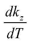

- Where Y is Young's modulus of the beam.
- The right hand term of the above equation may be re-expressed in terms of the parameters W, LS, LB and the linear thermal expansion coefficient of the cavity (CTEw), support (CTEs) and beam (CTEB) which leads to the following relationship:

- Where αB is the thermal expansion coefficient of the beam, W is the width of the cavity, Ls is the length of the beam 4, and LB is the length of the
support 8. Further, CTEw is the coefficient of thermal expansion of the substrate, CTEs is the coefficient of thermal expansion of the support and CTEb is the coefficient of thermal expansion of the beam. - Three separate cases may now be considered. In each case, a particular component of the resonator according to an embodiment of the invention will be considered in isolation of the other components forming the resonator.
- In this case the relationship set out in equation 5 above can be reduced to:

where CTEB is the coefficient of thermal expansion of the beam material. The dependence of this ratio as a function of θ is shown inFigure 2 . FromFigure 2 the angle θ required to maintain the temperature independence of spring constant kz is shown as a function of the ratio of the CTEB. - For a beam made of pure silicon the coefficient of thermal expansion of the beam will be 2.5e-6deg-1, and the thermal expansion coefficient to the beam αB will be 2e-4 deg-1.
- As can be seen from
Figure 2 in the resonator shown inFigure 1 it will be necessary for θ to be 10° in order that the temperature dependence of the elastic modulus is compensated for. - In this case the relation set out in equation 5 above can be reduced to:

where CTEs is the coefficient of thermal expansion of the support material. The dependence of this ratio is a function of θ is shown inFigure 3 for various support lengths which are expressed in units of beam length. Also shown inFigure 3 is the ratio αB/CTEs for a support beam made from pure silicon and also for a support beam made from Ni3Si. The coefficient of thermal expansion of Ni3Si is 15e-6 K-1. - By increasing the length of the support beam, moderate beam angles of approximately 45° can be used. In addition, alternative materials such as metal silicides having higher thermal expansion coefficients can be incorporated into the support beam further relaxing the requirements on the angle θ of the beam.
- When the support beam is formed from pure silicon, and the support beam is approximately 10 times the length of the beam, θ is required to be approximately 28°.
- If the support beam is formed from Ni3Si and is 10 times the length of the beam, then θ is required to be 60° due to the larger CTE of Ni3Si.
- The support beam may be formed from Ni3Si by reacting silicon with nickel (Ni) in a controlled manner.
- In this case the relation set out in equation 5 above can be reduced to:

where CTEW is the coefficient of thermal expansion of the substrate/cavity material. The dependence of this ratio as a function of θ is shown inFigure 4 . - Cavity expansion enhances rather than cancels αB. For a resonator formed from pure silicon there is no geometrical change and thus cavity expansion perfectly cancels the effect of the beam and support expansion.
- It can be seen from
Figures 2 to 4 and the description set out hereinabove that the CTE of the beam or the support must be enhanced relative to the cavity in order to compensate for any temperature coefficient of the Young's modulus. - It is preferred to form the beam from monocrystalline silicon due to the mechanical properties of this material. The CTE of the cavity is defined by the substrate material which is usually monocrystalline silicon. This means that if the CTE of the support is adjusted, substantial tuning of the compensation effect shown in
Figure 3 can be achieved using well controlled process steps and without impacting on the mechanical properties of the materials in critical regions. - In each of the three cases described above it is assumed that only the beam or only the support or only the cavity respectively expand with temperature.
- If all components expand at the same rate, as would be case if all components were formed from pure silicon system, then the geometry of the resonator will not change and the frequency will be purely dependent upon the Young's modulus.
- In practice it is the differences in the CTE between, for example the support and cavity materials that change the overall geometry of the resonator.
- An important feature of the present invention is that it is possible to tune the layout and material properties of the support in order to substantially perfectly compensate even if other expansion effects are included. For example the width, or the length, of the support may be altered in order to tune the resonator such that the effective spring constant of the resonator will remain substantially constant within a desired operating temperature range of the resonator.
- Turning now to
Figures 5 and 6 , a second embodiment of the invention is shown. Parts of theresonator 20 that correspond to parts of the resonator 2 illustrated inFigure 1 above have been given corresponding reference numerals for ease of reference. - The
resonator 20 comprisessupports 80 that support abeam 6. The supports 80 are formed from Ni3Si. In other respects, the configuration ofresonator 20 is similar to that of resonator 2 illustrated inFigure 1 .Figure 6 shows thecavity 82 located beneath thebeam 6.
Claims (12)
- A resonator (2) having an effective spring constant (kz) and comprising a beam (4) having a beam spring constant (kB) adapted to resonate in an oscillation direction, and extending at a non-zero angle (θ) to the oscillation direction, wherein the resonator has a predetermined geometry and is formed from one or more materials, the or each material having a coefficient of thermal expansion (CTE), the CTE of the or each material together with the predetermined geometry of the resonator causing θ to vary with temperature, such that the temperature dependence of the beam spring constant is compensated for, resulting in the effective spring constant of the resonator remaining substantially constant within an operating temperature range.
- A resonator (2) according to Claim 1 comprising a micromechanical resonator, wherein the beam (4) is formed from silicon.
- A resonator (2) according to Claim 1 or Claim 2 wherein the resonator is integrally formed in a silicon substrate.
- A resonator (2) according to any one of the preceding claims further comprising a support (6) supporting the beam, and a cavity defined below the beam.
- A resonator (2) according to any one of the preceding claims wherein θ falls within the range of 10° to 60°, preferably 10° to 45°, more preferably 10° to 30°.
- A resonator (2) according to Claim 2 wherein the support (6) has a length that is substantially 10 times the length of the beam (4) and wherein θ is substantially 28°.
- A resonator (2) according to any one of the preceding claims wherein the support (6) is formed from Ni3Si.
- A resonator (2) according to Claim 7 wherein the support (6) has a length that is 10 times the length of the beam (4).
- A method of tuning a resonator (2), the resonator having an effective spring constant (kz) and comprising a beam having a beam (4) spring constant (kB) adapted to resonate in an oscillation direction, and extending at a non-zero angle (θ) to the oscillation direction, wherein the resonator has a predetermined geometry and is formed from one or more materials, the or each material having a coefficient of thermal expansion (CTE), the CTE of the or each material together with the predetermined geometry of the resonator causing θ to vary with temperature, such that the temperature dependence of the beam spring constant is compensated for, the method comprising the step of altering the geometry of the resonator whereby the effective spring constant of the resonator will remain substantially constant within an operating temperature range.
- A method according to Claim 9 comprising the step of forming the resonator from a silicon substrate.
- A method according to Claim 9 or Claim 10 wherein the resonator comprises a support supporting the beam, and the step of altering the geometry of the resonator comprises the step of altering one or more dimensions of the support.
- A method according to Claim 11 comprising the step of forming the beam from Ni3Si.
Priority Applications (3)
| Application Number | Priority Date | Filing Date | Title |
|---|---|---|---|
| EP09252287.9A EP2339748B1 (en) | 2009-09-28 | 2009-09-28 | Resonator |
| CN201010293408.4A CN102035494B (en) | 2009-09-28 | 2010-09-26 | Resonator |
| US12/892,672 US8179201B2 (en) | 2009-09-28 | 2010-09-28 | Resonator |
Applications Claiming Priority (1)
| Application Number | Priority Date | Filing Date | Title |
|---|---|---|---|
| EP09252287.9A EP2339748B1 (en) | 2009-09-28 | 2009-09-28 | Resonator |
Publications (2)
| Publication Number | Publication Date |
|---|---|
| EP2339748A1 true EP2339748A1 (en) | 2011-06-29 |
| EP2339748B1 EP2339748B1 (en) | 2018-12-19 |
Family
ID=41328873
Family Applications (1)
| Application Number | Title | Priority Date | Filing Date |
|---|---|---|---|
| EP09252287.9A Not-in-force EP2339748B1 (en) | 2009-09-28 | 2009-09-28 | Resonator |
Country Status (3)
| Country | Link |
|---|---|
| US (1) | US8179201B2 (en) |
| EP (1) | EP2339748B1 (en) |
| CN (1) | CN102035494B (en) |
Families Citing this family (7)
| Publication number | Priority date | Publication date | Assignee | Title |
|---|---|---|---|---|
| US8821009B2 (en) * | 2009-12-23 | 2014-09-02 | Intel Corporation | Thermal sensors having flexible substrates and use thereof |
| US9233832B2 (en) | 2013-05-10 | 2016-01-12 | Globalfoundries Inc. | Micro-electro-mechanical system (MEMS) structures and design structures |
| TWI538396B (en) * | 2013-05-20 | 2016-06-11 | 國立清華大學 | Microelectromechanical resonator active temperature compensation method and resonator thereof |
| WO2018123118A1 (en) * | 2016-12-27 | 2018-07-05 | 株式会社村田製作所 | Resonance device |
| EP3641135B1 (en) * | 2018-10-17 | 2022-08-03 | NXP USA, Inc. | Frequency drift detector, communication unit and method therefor |
| JP2022129554A (en) | 2021-02-25 | 2022-09-06 | セイコーエプソン株式会社 | Vibration element and oscillator |
| JP2022139556A (en) * | 2021-03-12 | 2022-09-26 | セイコーエプソン株式会社 | vibrator and oscillator |
Citations (1)
| Publication number | Priority date | Publication date | Assignee | Title |
|---|---|---|---|---|
| WO2004095696A2 (en) | 2003-04-16 | 2004-11-04 | Robert Bosch Gmbh | Temperature compensation for silicon mems resonator |
Family Cites Families (8)
| Publication number | Priority date | Publication date | Assignee | Title |
|---|---|---|---|---|
| US6557419B1 (en) * | 1996-12-31 | 2003-05-06 | Honeywell International Inc. | Zero TCF thin film resonator |
| US6958566B2 (en) * | 2001-08-16 | 2005-10-25 | The Regents Of The University Of Michigan | Mechanical resonator device having phenomena-dependent electrical stiffness |
| EP1548935A1 (en) * | 2003-12-24 | 2005-06-29 | Interuniversitair Microelektronica Centrum Vzw | Micromachined film bulk acoustic resonator |
| US7211926B2 (en) * | 2005-03-09 | 2007-05-01 | The Regents Of The University Of California | Temperature compensated oscillator including MEMS resonator for frequency control |
| US7843283B2 (en) * | 2005-11-09 | 2010-11-30 | Cornell Research Foundation, Inc. | MEMS controlled oscillator |
| WO2007072409A2 (en) * | 2005-12-23 | 2007-06-28 | Nxp B.V. | A mems resonator, a method of manufacturing thereof, and a mems oscillator |
| US7443258B2 (en) * | 2006-04-06 | 2008-10-28 | Sitime Corporation | Oscillator system having a plurality of microelectromechanical resonators and method of designing, controlling or operating same |
| US7514853B1 (en) * | 2007-05-10 | 2009-04-07 | Silicon Clocks, Inc. | MEMS structure having a stress inverter temperature-compensated resonating member |
-
2009
- 2009-09-28 EP EP09252287.9A patent/EP2339748B1/en not_active Not-in-force
-
2010
- 2010-09-26 CN CN201010293408.4A patent/CN102035494B/en not_active Expired - Fee Related
- 2010-09-28 US US12/892,672 patent/US8179201B2/en not_active Expired - Fee Related
Patent Citations (1)
| Publication number | Priority date | Publication date | Assignee | Title |
|---|---|---|---|---|
| WO2004095696A2 (en) | 2003-04-16 | 2004-11-04 | Robert Bosch Gmbh | Temperature compensation for silicon mems resonator |
Non-Patent Citations (1)
| Title |
|---|
| No Search * |
Also Published As
| Publication number | Publication date |
|---|---|
| EP2339748B1 (en) | 2018-12-19 |
| US20110080224A1 (en) | 2011-04-07 |
| CN102035494B (en) | 2015-05-27 |
| CN102035494A (en) | 2011-04-27 |
| US8179201B2 (en) | 2012-05-15 |
Similar Documents
| Publication | Publication Date | Title |
|---|---|---|
| US8179201B2 (en) | Resonator | |
| KR100943777B1 (en) | How to compensate for thermally induced frequency fluctuations, how to manufacture micromechanical resonators, and micromechanical resonators | |
| EP2245738B1 (en) | A micromechanical resonator | |
| EP1925075B1 (en) | Breath-mode ring resonator structure, and method of designing, operating and using same | |
| US7514853B1 (en) | MEMS structure having a stress inverter temperature-compensated resonating member | |
| US11277112B2 (en) | Micro-electro-mechanical device with reduced temperature sensitivity and manufacturing method thereof | |
| Melamud et al. | Composite flexural-mode resonator with controllable turnover temperature | |
| US8981874B2 (en) | Resonator device and method of optimizing a Q-factor | |
| Ayazi et al. | Compensation, tuning, and trimming of MEMS resonators | |
| EP3000176B1 (en) | An improved microelectromechanical resonator | |
| US7938977B2 (en) | Method of modulating resonant frequency of torsional MEMS device | |
| EP3479475B1 (en) | Micromechanical resonator and method for trimming micromechanical resonator | |
| US8669687B2 (en) | Method of adjusting the resonance frequency of a micro-machined vibrating element |
Legal Events
| Date | Code | Title | Description |
|---|---|---|---|
| PUAI | Public reference made under article 153(3) epc to a published international application that has entered the european phase |
Free format text: ORIGINAL CODE: 0009012 |
|
| AK | Designated contracting states |
Kind code of ref document: A1 Designated state(s): AT BE BG CH CY CZ DE DK EE ES FI FR GB GR HR HU IE IS IT LI LT LU LV MC MK MT NL NO PL PT RO SE SI SK SM TR |
|
| AX | Request for extension of the european patent |
Extension state: AL BA RS |
|
| 17P | Request for examination filed |
Effective date: 20111229 |
|
| 17Q | First examination report despatched |
Effective date: 20120207 |
|
| GRAP | Despatch of communication of intention to grant a patent |
Free format text: ORIGINAL CODE: EPIDOSNIGR1 |
|
| STAA | Information on the status of an ep patent application or granted ep patent |
Free format text: STATUS: GRANT OF PATENT IS INTENDED |
|
| INTG | Intention to grant announced |
Effective date: 20180903 |
|
| RIN1 | Information on inventor provided before grant (corrected) |
Inventor name: LANDER, ROBERT JAMES PASCOE |
|
| GRAS | Grant fee paid |
Free format text: ORIGINAL CODE: EPIDOSNIGR3 |
|
| GRAA | (expected) grant |
Free format text: ORIGINAL CODE: 0009210 |
|
| STAA | Information on the status of an ep patent application or granted ep patent |
Free format text: STATUS: THE PATENT HAS BEEN GRANTED |
|
| AK | Designated contracting states |
Kind code of ref document: B1 Designated state(s): AT BE BG CH CY CZ DE DK EE ES FI FR GB GR HR HU IE IS IT LI LT LU LV MC MK MT NL NO PL PT RO SE SI SK SM TR |
|
| REG | Reference to a national code |
Ref country code: GB Ref legal event code: FG4D |
|
| REG | Reference to a national code |
Ref country code: CH Ref legal event code: EP |
|
| REG | Reference to a national code |
Ref country code: DE Ref legal event code: R096 Ref document number: 602009056256 Country of ref document: DE |
|
| REG | Reference to a national code |
Ref country code: IE Ref legal event code: FG4D |
|
| REG | Reference to a national code |
Ref country code: AT Ref legal event code: REF Ref document number: 1079775 Country of ref document: AT Kind code of ref document: T Effective date: 20190115 |
|
| REG | Reference to a national code |
Ref country code: NL Ref legal event code: MP Effective date: 20181219 |
|
| PG25 | Lapsed in a contracting state [announced via postgrant information from national office to epo] |
Ref country code: HR Free format text: LAPSE BECAUSE OF FAILURE TO SUBMIT A TRANSLATION OF THE DESCRIPTION OR TO PAY THE FEE WITHIN THE PRESCRIBED TIME-LIMIT Effective date: 20181219 Ref country code: LT Free format text: LAPSE BECAUSE OF FAILURE TO SUBMIT A TRANSLATION OF THE DESCRIPTION OR TO PAY THE FEE WITHIN THE PRESCRIBED TIME-LIMIT Effective date: 20181219 Ref country code: NO Free format text: LAPSE BECAUSE OF FAILURE TO SUBMIT A TRANSLATION OF THE DESCRIPTION OR TO PAY THE FEE WITHIN THE PRESCRIBED TIME-LIMIT Effective date: 20190319 Ref country code: BG Free format text: LAPSE BECAUSE OF FAILURE TO SUBMIT A TRANSLATION OF THE DESCRIPTION OR TO PAY THE FEE WITHIN THE PRESCRIBED TIME-LIMIT Effective date: 20190319 Ref country code: FI Free format text: LAPSE BECAUSE OF FAILURE TO SUBMIT A TRANSLATION OF THE DESCRIPTION OR TO PAY THE FEE WITHIN THE PRESCRIBED TIME-LIMIT Effective date: 20181219 Ref country code: LV Free format text: LAPSE BECAUSE OF FAILURE TO SUBMIT A TRANSLATION OF THE DESCRIPTION OR TO PAY THE FEE WITHIN THE PRESCRIBED TIME-LIMIT Effective date: 20181219 |
|
| REG | Reference to a national code |
Ref country code: LT Ref legal event code: MG4D |
|
| REG | Reference to a national code |
Ref country code: AT Ref legal event code: MK05 Ref document number: 1079775 Country of ref document: AT Kind code of ref document: T Effective date: 20181219 |
|
| PG25 | Lapsed in a contracting state [announced via postgrant information from national office to epo] |
Ref country code: GR Free format text: LAPSE BECAUSE OF FAILURE TO SUBMIT A TRANSLATION OF THE DESCRIPTION OR TO PAY THE FEE WITHIN THE PRESCRIBED TIME-LIMIT Effective date: 20190320 Ref country code: SE Free format text: LAPSE BECAUSE OF FAILURE TO SUBMIT A TRANSLATION OF THE DESCRIPTION OR TO PAY THE FEE WITHIN THE PRESCRIBED TIME-LIMIT Effective date: 20181219 |
|
| PG25 | Lapsed in a contracting state [announced via postgrant information from national office to epo] |
Ref country code: NL Free format text: LAPSE BECAUSE OF FAILURE TO SUBMIT A TRANSLATION OF THE DESCRIPTION OR TO PAY THE FEE WITHIN THE PRESCRIBED TIME-LIMIT Effective date: 20181219 |
|
| PG25 | Lapsed in a contracting state [announced via postgrant information from national office to epo] |
Ref country code: PL Free format text: LAPSE BECAUSE OF FAILURE TO SUBMIT A TRANSLATION OF THE DESCRIPTION OR TO PAY THE FEE WITHIN THE PRESCRIBED TIME-LIMIT Effective date: 20181219 Ref country code: PT Free format text: LAPSE BECAUSE OF FAILURE TO SUBMIT A TRANSLATION OF THE DESCRIPTION OR TO PAY THE FEE WITHIN THE PRESCRIBED TIME-LIMIT Effective date: 20190419 Ref country code: IT Free format text: LAPSE BECAUSE OF FAILURE TO SUBMIT A TRANSLATION OF THE DESCRIPTION OR TO PAY THE FEE WITHIN THE PRESCRIBED TIME-LIMIT Effective date: 20181219 Ref country code: ES Free format text: LAPSE BECAUSE OF FAILURE TO SUBMIT A TRANSLATION OF THE DESCRIPTION OR TO PAY THE FEE WITHIN THE PRESCRIBED TIME-LIMIT Effective date: 20181219 Ref country code: CZ Free format text: LAPSE BECAUSE OF FAILURE TO SUBMIT A TRANSLATION OF THE DESCRIPTION OR TO PAY THE FEE WITHIN THE PRESCRIBED TIME-LIMIT Effective date: 20181219 |
|
| PG25 | Lapsed in a contracting state [announced via postgrant information from national office to epo] |
Ref country code: RO Free format text: LAPSE BECAUSE OF FAILURE TO SUBMIT A TRANSLATION OF THE DESCRIPTION OR TO PAY THE FEE WITHIN THE PRESCRIBED TIME-LIMIT Effective date: 20181219 Ref country code: IS Free format text: LAPSE BECAUSE OF FAILURE TO SUBMIT A TRANSLATION OF THE DESCRIPTION OR TO PAY THE FEE WITHIN THE PRESCRIBED TIME-LIMIT Effective date: 20190419 Ref country code: SM Free format text: LAPSE BECAUSE OF FAILURE TO SUBMIT A TRANSLATION OF THE DESCRIPTION OR TO PAY THE FEE WITHIN THE PRESCRIBED TIME-LIMIT Effective date: 20181219 Ref country code: EE Free format text: LAPSE BECAUSE OF FAILURE TO SUBMIT A TRANSLATION OF THE DESCRIPTION OR TO PAY THE FEE WITHIN THE PRESCRIBED TIME-LIMIT Effective date: 20181219 Ref country code: SK Free format text: LAPSE BECAUSE OF FAILURE TO SUBMIT A TRANSLATION OF THE DESCRIPTION OR TO PAY THE FEE WITHIN THE PRESCRIBED TIME-LIMIT Effective date: 20181219 |
|
| REG | Reference to a national code |
Ref country code: DE Ref legal event code: R097 Ref document number: 602009056256 Country of ref document: DE |
|
| PLBE | No opposition filed within time limit |
Free format text: ORIGINAL CODE: 0009261 |
|
| STAA | Information on the status of an ep patent application or granted ep patent |
Free format text: STATUS: NO OPPOSITION FILED WITHIN TIME LIMIT |
|
| PG25 | Lapsed in a contracting state [announced via postgrant information from national office to epo] |
Ref country code: DK Free format text: LAPSE BECAUSE OF FAILURE TO SUBMIT A TRANSLATION OF THE DESCRIPTION OR TO PAY THE FEE WITHIN THE PRESCRIBED TIME-LIMIT Effective date: 20181219 Ref country code: AT Free format text: LAPSE BECAUSE OF FAILURE TO SUBMIT A TRANSLATION OF THE DESCRIPTION OR TO PAY THE FEE WITHIN THE PRESCRIBED TIME-LIMIT Effective date: 20181219 |
|
| PGFP | Annual fee paid to national office [announced via postgrant information from national office to epo] |
Ref country code: DE Payment date: 20190820 Year of fee payment: 11 |
|
| 26N | No opposition filed |
Effective date: 20190920 |
|
| PG25 | Lapsed in a contracting state [announced via postgrant information from national office to epo] |
Ref country code: SI Free format text: LAPSE BECAUSE OF FAILURE TO SUBMIT A TRANSLATION OF THE DESCRIPTION OR TO PAY THE FEE WITHIN THE PRESCRIBED TIME-LIMIT Effective date: 20181219 |
|
| PG25 | Lapsed in a contracting state [announced via postgrant information from national office to epo] |
Ref country code: TR Free format text: LAPSE BECAUSE OF FAILURE TO SUBMIT A TRANSLATION OF THE DESCRIPTION OR TO PAY THE FEE WITHIN THE PRESCRIBED TIME-LIMIT Effective date: 20181219 |
|
| PG25 | Lapsed in a contracting state [announced via postgrant information from national office to epo] |
Ref country code: MC Free format text: LAPSE BECAUSE OF FAILURE TO SUBMIT A TRANSLATION OF THE DESCRIPTION OR TO PAY THE FEE WITHIN THE PRESCRIBED TIME-LIMIT Effective date: 20181219 |
|
| REG | Reference to a national code |
Ref country code: CH Ref legal event code: PL |
|
| PG25 | Lapsed in a contracting state [announced via postgrant information from national office to epo] |
Ref country code: IE Free format text: LAPSE BECAUSE OF NON-PAYMENT OF DUE FEES Effective date: 20190928 Ref country code: LU Free format text: LAPSE BECAUSE OF NON-PAYMENT OF DUE FEES Effective date: 20190928 Ref country code: LI Free format text: LAPSE BECAUSE OF NON-PAYMENT OF DUE FEES Effective date: 20190930 Ref country code: CH Free format text: LAPSE BECAUSE OF NON-PAYMENT OF DUE FEES Effective date: 20190930 |
|
| REG | Reference to a national code |
Ref country code: BE Ref legal event code: MM Effective date: 20190930 |
|
| PG25 | Lapsed in a contracting state [announced via postgrant information from national office to epo] |
Ref country code: BE Free format text: LAPSE BECAUSE OF NON-PAYMENT OF DUE FEES Effective date: 20190930 |
|
| GBPC | Gb: european patent ceased through non-payment of renewal fee |
Effective date: 20190928 |
|
| PG25 | Lapsed in a contracting state [announced via postgrant information from national office to epo] |
Ref country code: GB Free format text: LAPSE BECAUSE OF NON-PAYMENT OF DUE FEES Effective date: 20190928 Ref country code: FR Free format text: LAPSE BECAUSE OF NON-PAYMENT OF DUE FEES Effective date: 20190930 |
|
| REG | Reference to a national code |
Ref country code: DE Ref legal event code: R119 Ref document number: 602009056256 Country of ref document: DE |
|
| PG25 | Lapsed in a contracting state [announced via postgrant information from national office to epo] |
Ref country code: CY Free format text: LAPSE BECAUSE OF FAILURE TO SUBMIT A TRANSLATION OF THE DESCRIPTION OR TO PAY THE FEE WITHIN THE PRESCRIBED TIME-LIMIT Effective date: 20181219 |
|
| PG25 | Lapsed in a contracting state [announced via postgrant information from national office to epo] |
Ref country code: HU Free format text: LAPSE BECAUSE OF FAILURE TO SUBMIT A TRANSLATION OF THE DESCRIPTION OR TO PAY THE FEE WITHIN THE PRESCRIBED TIME-LIMIT; INVALID AB INITIO Effective date: 20090928 Ref country code: DE Free format text: LAPSE BECAUSE OF NON-PAYMENT OF DUE FEES Effective date: 20210401 Ref country code: MT Free format text: LAPSE BECAUSE OF FAILURE TO SUBMIT A TRANSLATION OF THE DESCRIPTION OR TO PAY THE FEE WITHIN THE PRESCRIBED TIME-LIMIT Effective date: 20181219 |
|
| PG25 | Lapsed in a contracting state [announced via postgrant information from national office to epo] |
Ref country code: MK Free format text: LAPSE BECAUSE OF FAILURE TO SUBMIT A TRANSLATION OF THE DESCRIPTION OR TO PAY THE FEE WITHIN THE PRESCRIBED TIME-LIMIT Effective date: 20181219 |