EP2339133A1 - Method and system for operating a combined cycle power plant - Google Patents
Method and system for operating a combined cycle power plant Download PDFInfo
- Publication number
- EP2339133A1 EP2339133A1 EP09178314A EP09178314A EP2339133A1 EP 2339133 A1 EP2339133 A1 EP 2339133A1 EP 09178314 A EP09178314 A EP 09178314A EP 09178314 A EP09178314 A EP 09178314A EP 2339133 A1 EP2339133 A1 EP 2339133A1
- Authority
- EP
- European Patent Office
- Prior art keywords
- guide vane
- power source
- external power
- variable guide
- booster
- Prior art date
- Legal status (The legal status is an assumption and is not a legal conclusion. Google has not performed a legal analysis and makes no representation as to the accuracy of the status listed.)
- Granted
Links
- 238000000034 method Methods 0.000 title claims description 40
- 238000002485 combustion reaction Methods 0.000 claims abstract description 14
- 238000004891 communication Methods 0.000 claims description 37
- 238000000926 separation method Methods 0.000 claims description 22
- 230000008878 coupling Effects 0.000 claims description 12
- 238000010168 coupling process Methods 0.000 claims description 12
- 238000005859 coupling reaction Methods 0.000 claims description 12
- 239000000446 fuel Substances 0.000 claims description 11
- 238000002309 gasification Methods 0.000 claims description 11
- 239000007800 oxidant agent Substances 0.000 claims description 5
- 230000001590 oxidative effect Effects 0.000 claims description 5
- 239000003502 gasoline Substances 0.000 claims description 3
- 230000000977 initiatory effect Effects 0.000 claims description 3
- 239000003570 air Substances 0.000 description 59
- 239000007789 gas Substances 0.000 description 47
- 238000010586 diagram Methods 0.000 description 13
- 238000010248 power generation Methods 0.000 description 13
- 238000004590 computer program Methods 0.000 description 12
- 230000006870 function Effects 0.000 description 9
- 230000008569 process Effects 0.000 description 8
- IJGRMHOSHXDMSA-UHFFFAOYSA-N Atomic nitrogen Chemical compound N#N IJGRMHOSHXDMSA-UHFFFAOYSA-N 0.000 description 6
- 239000007858 starting material Substances 0.000 description 6
- CURLTUGMZLYLDI-UHFFFAOYSA-N Carbon dioxide Chemical compound O=C=O CURLTUGMZLYLDI-UHFFFAOYSA-N 0.000 description 5
- QVGXLLKOCUKJST-UHFFFAOYSA-N atomic oxygen Chemical compound [O] QVGXLLKOCUKJST-UHFFFAOYSA-N 0.000 description 5
- 239000001301 oxygen Substances 0.000 description 5
- 229910052760 oxygen Inorganic materials 0.000 description 5
- 238000003860 storage Methods 0.000 description 5
- 230000003287 optical effect Effects 0.000 description 4
- 229910002092 carbon dioxide Inorganic materials 0.000 description 3
- 239000001569 carbon dioxide Substances 0.000 description 3
- 229910052757 nitrogen Inorganic materials 0.000 description 3
- XLYOFNOQVPJJNP-UHFFFAOYSA-N water Substances O XLYOFNOQVPJJNP-UHFFFAOYSA-N 0.000 description 3
- XKRFYHLGVUSROY-UHFFFAOYSA-N Argon Chemical compound [Ar] XKRFYHLGVUSROY-UHFFFAOYSA-N 0.000 description 2
- GQPLMRYTRLFLPF-UHFFFAOYSA-N Nitrous Oxide Chemical compound [O-][N+]#N GQPLMRYTRLFLPF-UHFFFAOYSA-N 0.000 description 2
- 239000006227 byproduct Substances 0.000 description 2
- 238000001816 cooling Methods 0.000 description 2
- 230000003071 parasitic effect Effects 0.000 description 2
- 238000011084 recovery Methods 0.000 description 2
- 235000019738 Limestone Nutrition 0.000 description 1
- 230000009471 action Effects 0.000 description 1
- 230000006978 adaptation Effects 0.000 description 1
- 239000012080 ambient air Substances 0.000 description 1
- 229910052786 argon Inorganic materials 0.000 description 1
- 230000005540 biological transmission Effects 0.000 description 1
- -1 but not limited to Substances 0.000 description 1
- 230000001413 cellular effect Effects 0.000 description 1
- 230000008859 change Effects 0.000 description 1
- 230000005465 channeling Effects 0.000 description 1
- 238000004140 cleaning Methods 0.000 description 1
- 239000003245 coal Substances 0.000 description 1
- 239000012809 cooling fluid Substances 0.000 description 1
- 230000001419 dependent effect Effects 0.000 description 1
- 230000000694 effects Effects 0.000 description 1
- 239000000839 emulsion Substances 0.000 description 1
- 230000007717 exclusion Effects 0.000 description 1
- 238000002347 injection Methods 0.000 description 1
- 239000007924 injection Substances 0.000 description 1
- 239000006028 limestone Substances 0.000 description 1
- 238000004519 manufacturing process Methods 0.000 description 1
- 239000000203 mixture Substances 0.000 description 1
- 239000001272 nitrous oxide Substances 0.000 description 1
- 239000013307 optical fiber Substances 0.000 description 1
- 239000002006 petroleum coke Substances 0.000 description 1
- 230000009467 reduction Effects 0.000 description 1
- 239000004065 semiconductor Substances 0.000 description 1
- 230000001360 synchronised effect Effects 0.000 description 1
- 238000011144 upstream manufacturing Methods 0.000 description 1
Images



Classifications
-
- F—MECHANICAL ENGINEERING; LIGHTING; HEATING; WEAPONS; BLASTING
- F02—COMBUSTION ENGINES; HOT-GAS OR COMBUSTION-PRODUCT ENGINE PLANTS
- F02C—GAS-TURBINE PLANTS; AIR INTAKES FOR JET-PROPULSION PLANTS; CONTROLLING FUEL SUPPLY IN AIR-BREATHING JET-PROPULSION PLANTS
- F02C3/00—Gas-turbine plants characterised by the use of combustion products as the working fluid
- F02C3/20—Gas-turbine plants characterised by the use of combustion products as the working fluid using a special fuel, oxidant, or dilution fluid to generate the combustion products
- F02C3/26—Gas-turbine plants characterised by the use of combustion products as the working fluid using a special fuel, oxidant, or dilution fluid to generate the combustion products the fuel or oxidant being solid or pulverulent, e.g. in slurry or suspension
- F02C3/28—Gas-turbine plants characterised by the use of combustion products as the working fluid using a special fuel, oxidant, or dilution fluid to generate the combustion products the fuel or oxidant being solid or pulverulent, e.g. in slurry or suspension using a separate gas producer for gasifying the fuel before combustion
-
- F—MECHANICAL ENGINEERING; LIGHTING; HEATING; WEAPONS; BLASTING
- F01—MACHINES OR ENGINES IN GENERAL; ENGINE PLANTS IN GENERAL; STEAM ENGINES
- F01K—STEAM ENGINE PLANTS; STEAM ACCUMULATORS; ENGINE PLANTS NOT OTHERWISE PROVIDED FOR; ENGINES USING SPECIAL WORKING FLUIDS OR CYCLES
- F01K23/00—Plants characterised by more than one engine delivering power external to the plant, the engines being driven by different fluids
- F01K23/02—Plants characterised by more than one engine delivering power external to the plant, the engines being driven by different fluids the engine cycles being thermally coupled
- F01K23/06—Plants characterised by more than one engine delivering power external to the plant, the engines being driven by different fluids the engine cycles being thermally coupled combustion heat from one cycle heating the fluid in another cycle
- F01K23/067—Plants characterised by more than one engine delivering power external to the plant, the engines being driven by different fluids the engine cycles being thermally coupled combustion heat from one cycle heating the fluid in another cycle the combustion heat coming from a gasification or pyrolysis process, e.g. coal gasification
- F01K23/068—Plants characterised by more than one engine delivering power external to the plant, the engines being driven by different fluids the engine cycles being thermally coupled combustion heat from one cycle heating the fluid in another cycle the combustion heat coming from a gasification or pyrolysis process, e.g. coal gasification in combination with an oxygen producing plant, e.g. an air separation plant
-
- F—MECHANICAL ENGINEERING; LIGHTING; HEATING; WEAPONS; BLASTING
- F02—COMBUSTION ENGINES; HOT-GAS OR COMBUSTION-PRODUCT ENGINE PLANTS
- F02C—GAS-TURBINE PLANTS; AIR INTAKES FOR JET-PROPULSION PLANTS; CONTROLLING FUEL SUPPLY IN AIR-BREATHING JET-PROPULSION PLANTS
- F02C6/00—Plural gas-turbine plants; Combinations of gas-turbine plants with other apparatus; Adaptations of gas-turbine plants for special use
- F02C6/18—Plural gas-turbine plants; Combinations of gas-turbine plants with other apparatus; Adaptations of gas-turbine plants for special use using the waste heat of gas-turbine plants outside the plants themselves, e.g. gas-turbine power heat plants
-
- F—MECHANICAL ENGINEERING; LIGHTING; HEATING; WEAPONS; BLASTING
- F25—REFRIGERATION OR COOLING; COMBINED HEATING AND REFRIGERATION SYSTEMS; HEAT PUMP SYSTEMS; MANUFACTURE OR STORAGE OF ICE; LIQUEFACTION SOLIDIFICATION OF GASES
- F25J—LIQUEFACTION, SOLIDIFICATION OR SEPARATION OF GASES OR GASEOUS OR LIQUEFIED GASEOUS MIXTURES BY PRESSURE AND COLD TREATMENT OR BY BRINGING THEM INTO THE SUPERCRITICAL STATE
- F25J3/00—Processes or apparatus for separating the constituents of gaseous or liquefied gaseous mixtures involving the use of liquefaction or solidification
- F25J3/02—Processes or apparatus for separating the constituents of gaseous or liquefied gaseous mixtures involving the use of liquefaction or solidification by rectification, i.e. by continuous interchange of heat and material between a vapour stream and a liquid stream
- F25J3/04—Processes or apparatus for separating the constituents of gaseous or liquefied gaseous mixtures involving the use of liquefaction or solidification by rectification, i.e. by continuous interchange of heat and material between a vapour stream and a liquid stream for air
- F25J3/04006—Providing pressurised feed air or process streams within or from the air fractionation unit
- F25J3/04012—Providing pressurised feed air or process streams within or from the air fractionation unit by compression of warm gaseous streams; details of intake or interstage cooling
- F25J3/04018—Providing pressurised feed air or process streams within or from the air fractionation unit by compression of warm gaseous streams; details of intake or interstage cooling of main feed air
-
- F—MECHANICAL ENGINEERING; LIGHTING; HEATING; WEAPONS; BLASTING
- F25—REFRIGERATION OR COOLING; COMBINED HEATING AND REFRIGERATION SYSTEMS; HEAT PUMP SYSTEMS; MANUFACTURE OR STORAGE OF ICE; LIQUEFACTION SOLIDIFICATION OF GASES
- F25J—LIQUEFACTION, SOLIDIFICATION OR SEPARATION OF GASES OR GASEOUS OR LIQUEFIED GASEOUS MIXTURES BY PRESSURE AND COLD TREATMENT OR BY BRINGING THEM INTO THE SUPERCRITICAL STATE
- F25J3/00—Processes or apparatus for separating the constituents of gaseous or liquefied gaseous mixtures involving the use of liquefaction or solidification
- F25J3/02—Processes or apparatus for separating the constituents of gaseous or liquefied gaseous mixtures involving the use of liquefaction or solidification by rectification, i.e. by continuous interchange of heat and material between a vapour stream and a liquid stream
- F25J3/04—Processes or apparatus for separating the constituents of gaseous or liquefied gaseous mixtures involving the use of liquefaction or solidification by rectification, i.e. by continuous interchange of heat and material between a vapour stream and a liquid stream for air
- F25J3/04006—Providing pressurised feed air or process streams within or from the air fractionation unit
- F25J3/04109—Arrangements of compressors and /or their drivers
- F25J3/04115—Arrangements of compressors and /or their drivers characterised by the type of prime driver, e.g. hot gas expander
-
- F—MECHANICAL ENGINEERING; LIGHTING; HEATING; WEAPONS; BLASTING
- F25—REFRIGERATION OR COOLING; COMBINED HEATING AND REFRIGERATION SYSTEMS; HEAT PUMP SYSTEMS; MANUFACTURE OR STORAGE OF ICE; LIQUEFACTION SOLIDIFICATION OF GASES
- F25J—LIQUEFACTION, SOLIDIFICATION OR SEPARATION OF GASES OR GASEOUS OR LIQUEFIED GASEOUS MIXTURES BY PRESSURE AND COLD TREATMENT OR BY BRINGING THEM INTO THE SUPERCRITICAL STATE
- F25J3/00—Processes or apparatus for separating the constituents of gaseous or liquefied gaseous mixtures involving the use of liquefaction or solidification
- F25J3/02—Processes or apparatus for separating the constituents of gaseous or liquefied gaseous mixtures involving the use of liquefaction or solidification by rectification, i.e. by continuous interchange of heat and material between a vapour stream and a liquid stream
- F25J3/04—Processes or apparatus for separating the constituents of gaseous or liquefied gaseous mixtures involving the use of liquefaction or solidification by rectification, i.e. by continuous interchange of heat and material between a vapour stream and a liquid stream for air
- F25J3/04006—Providing pressurised feed air or process streams within or from the air fractionation unit
- F25J3/04109—Arrangements of compressors and /or their drivers
- F25J3/04139—Combination of different types of drivers mechanically coupled to the same compressor, possibly split on multiple compressor casings
-
- F—MECHANICAL ENGINEERING; LIGHTING; HEATING; WEAPONS; BLASTING
- F25—REFRIGERATION OR COOLING; COMBINED HEATING AND REFRIGERATION SYSTEMS; HEAT PUMP SYSTEMS; MANUFACTURE OR STORAGE OF ICE; LIQUEFACTION SOLIDIFICATION OF GASES
- F25J—LIQUEFACTION, SOLIDIFICATION OR SEPARATION OF GASES OR GASEOUS OR LIQUEFIED GASEOUS MIXTURES BY PRESSURE AND COLD TREATMENT OR BY BRINGING THEM INTO THE SUPERCRITICAL STATE
- F25J3/00—Processes or apparatus for separating the constituents of gaseous or liquefied gaseous mixtures involving the use of liquefaction or solidification
- F25J3/02—Processes or apparatus for separating the constituents of gaseous or liquefied gaseous mixtures involving the use of liquefaction or solidification by rectification, i.e. by continuous interchange of heat and material between a vapour stream and a liquid stream
- F25J3/04—Processes or apparatus for separating the constituents of gaseous or liquefied gaseous mixtures involving the use of liquefaction or solidification by rectification, i.e. by continuous interchange of heat and material between a vapour stream and a liquid stream for air
- F25J3/04521—Coupling of the air fractionation unit to an air gas-consuming unit, so-called integrated processes
- F25J3/04527—Integration with an oxygen consuming unit, e.g. glass facility, waste incineration or oxygen based processes in general
- F25J3/04539—Integration with an oxygen consuming unit, e.g. glass facility, waste incineration or oxygen based processes in general for the H2/CO synthesis by partial oxidation or oxygen consuming reforming processes of fuels
- F25J3/04545—Integration with an oxygen consuming unit, e.g. glass facility, waste incineration or oxygen based processes in general for the H2/CO synthesis by partial oxidation or oxygen consuming reforming processes of fuels for the gasification of solid or heavy liquid fuels, e.g. integrated gasification combined cycle [IGCC]
-
- F—MECHANICAL ENGINEERING; LIGHTING; HEATING; WEAPONS; BLASTING
- F25—REFRIGERATION OR COOLING; COMBINED HEATING AND REFRIGERATION SYSTEMS; HEAT PUMP SYSTEMS; MANUFACTURE OR STORAGE OF ICE; LIQUEFACTION SOLIDIFICATION OF GASES
- F25J—LIQUEFACTION, SOLIDIFICATION OR SEPARATION OF GASES OR GASEOUS OR LIQUEFIED GASEOUS MIXTURES BY PRESSURE AND COLD TREATMENT OR BY BRINGING THEM INTO THE SUPERCRITICAL STATE
- F25J3/00—Processes or apparatus for separating the constituents of gaseous or liquefied gaseous mixtures involving the use of liquefaction or solidification
- F25J3/02—Processes or apparatus for separating the constituents of gaseous or liquefied gaseous mixtures involving the use of liquefaction or solidification by rectification, i.e. by continuous interchange of heat and material between a vapour stream and a liquid stream
- F25J3/04—Processes or apparatus for separating the constituents of gaseous or liquefied gaseous mixtures involving the use of liquefaction or solidification by rectification, i.e. by continuous interchange of heat and material between a vapour stream and a liquid stream for air
- F25J3/04521—Coupling of the air fractionation unit to an air gas-consuming unit, so-called integrated processes
- F25J3/04563—Integration with a nitrogen consuming unit, e.g. for purging, inerting, cooling or heating
- F25J3/04575—Integration with a nitrogen consuming unit, e.g. for purging, inerting, cooling or heating for a gas expansion plant, e.g. dilution of the combustion gas in a gas turbine
-
- F—MECHANICAL ENGINEERING; LIGHTING; HEATING; WEAPONS; BLASTING
- F25—REFRIGERATION OR COOLING; COMBINED HEATING AND REFRIGERATION SYSTEMS; HEAT PUMP SYSTEMS; MANUFACTURE OR STORAGE OF ICE; LIQUEFACTION SOLIDIFICATION OF GASES
- F25J—LIQUEFACTION, SOLIDIFICATION OR SEPARATION OF GASES OR GASEOUS OR LIQUEFIED GASEOUS MIXTURES BY PRESSURE AND COLD TREATMENT OR BY BRINGING THEM INTO THE SUPERCRITICAL STATE
- F25J3/00—Processes or apparatus for separating the constituents of gaseous or liquefied gaseous mixtures involving the use of liquefaction or solidification
- F25J3/02—Processes or apparatus for separating the constituents of gaseous or liquefied gaseous mixtures involving the use of liquefaction or solidification by rectification, i.e. by continuous interchange of heat and material between a vapour stream and a liquid stream
- F25J3/04—Processes or apparatus for separating the constituents of gaseous or liquefied gaseous mixtures involving the use of liquefaction or solidification by rectification, i.e. by continuous interchange of heat and material between a vapour stream and a liquid stream for air
- F25J3/04521—Coupling of the air fractionation unit to an air gas-consuming unit, so-called integrated processes
- F25J3/04593—The air gas consuming unit is also fed by an air stream
- F25J3/046—Completely integrated air feed compression, i.e. common MAC
-
- F—MECHANICAL ENGINEERING; LIGHTING; HEATING; WEAPONS; BLASTING
- F25—REFRIGERATION OR COOLING; COMBINED HEATING AND REFRIGERATION SYSTEMS; HEAT PUMP SYSTEMS; MANUFACTURE OR STORAGE OF ICE; LIQUEFACTION SOLIDIFICATION OF GASES
- F25J—LIQUEFACTION, SOLIDIFICATION OR SEPARATION OF GASES OR GASEOUS OR LIQUEFIED GASEOUS MIXTURES BY PRESSURE AND COLD TREATMENT OR BY BRINGING THEM INTO THE SUPERCRITICAL STATE
- F25J3/00—Processes or apparatus for separating the constituents of gaseous or liquefied gaseous mixtures involving the use of liquefaction or solidification
- F25J3/02—Processes or apparatus for separating the constituents of gaseous or liquefied gaseous mixtures involving the use of liquefaction or solidification by rectification, i.e. by continuous interchange of heat and material between a vapour stream and a liquid stream
- F25J3/04—Processes or apparatus for separating the constituents of gaseous or liquefied gaseous mixtures involving the use of liquefaction or solidification by rectification, i.e. by continuous interchange of heat and material between a vapour stream and a liquid stream for air
- F25J3/04763—Start-up or control of the process; Details of the apparatus used
- F25J3/04769—Operation, control and regulation of the process; Instrumentation within the process
- F25J3/04781—Pressure changing devices, e.g. for compression, expansion, liquid pumping
-
- F—MECHANICAL ENGINEERING; LIGHTING; HEATING; WEAPONS; BLASTING
- F25—REFRIGERATION OR COOLING; COMBINED HEATING AND REFRIGERATION SYSTEMS; HEAT PUMP SYSTEMS; MANUFACTURE OR STORAGE OF ICE; LIQUEFACTION SOLIDIFICATION OF GASES
- F25J—LIQUEFACTION, SOLIDIFICATION OR SEPARATION OF GASES OR GASEOUS OR LIQUEFIED GASEOUS MIXTURES BY PRESSURE AND COLD TREATMENT OR BY BRINGING THEM INTO THE SUPERCRITICAL STATE
- F25J2230/00—Processes or apparatus involving steps for increasing the pressure of gaseous process streams
- F25J2230/40—Processes or apparatus involving steps for increasing the pressure of gaseous process streams the fluid being air
-
- Y—GENERAL TAGGING OF NEW TECHNOLOGICAL DEVELOPMENTS; GENERAL TAGGING OF CROSS-SECTIONAL TECHNOLOGIES SPANNING OVER SEVERAL SECTIONS OF THE IPC; TECHNICAL SUBJECTS COVERED BY FORMER USPC CROSS-REFERENCE ART COLLECTIONS [XRACs] AND DIGESTS
- Y02—TECHNOLOGIES OR APPLICATIONS FOR MITIGATION OR ADAPTATION AGAINST CLIMATE CHANGE
- Y02E—REDUCTION OF GREENHOUSE GAS [GHG] EMISSIONS, RELATED TO ENERGY GENERATION, TRANSMISSION OR DISTRIBUTION
- Y02E20/00—Combustion technologies with mitigation potential
- Y02E20/16—Combined cycle power plant [CCPP], or combined cycle gas turbine [CCGT]
-
- Y—GENERAL TAGGING OF NEW TECHNOLOGICAL DEVELOPMENTS; GENERAL TAGGING OF CROSS-SECTIONAL TECHNOLOGIES SPANNING OVER SEVERAL SECTIONS OF THE IPC; TECHNICAL SUBJECTS COVERED BY FORMER USPC CROSS-REFERENCE ART COLLECTIONS [XRACs] AND DIGESTS
- Y02—TECHNOLOGIES OR APPLICATIONS FOR MITIGATION OR ADAPTATION AGAINST CLIMATE CHANGE
- Y02E—REDUCTION OF GREENHOUSE GAS [GHG] EMISSIONS, RELATED TO ENERGY GENERATION, TRANSMISSION OR DISTRIBUTION
- Y02E20/00—Combustion technologies with mitigation potential
- Y02E20/16—Combined cycle power plant [CCPP], or combined cycle gas turbine [CCGT]
- Y02E20/18—Integrated gasification combined cycle [IGCC], e.g. combined with carbon capture and storage [CCS]
Definitions
- This invention relates generally to power generation systems and, more particularly, to combined cycle power plants that include large variable speed process equipment.
- Some known integrated gasification combined cycle (IGCC) power plants use an air separation unit to generate a flow of oxidant for the gasification process.
- the air separation unit requires a source of relatively constant flow and pressure compressed air.
- a motor driven compressor is typically used for providing the compressed air at the necessary flow and pressure.
- the motor driven compressor is an expensive piece of equipment that uses significant electrical power.
- the motor driven compressor may be considered a parasitic load on the IGCC power plant, leading to a reduction in the overall efficiency.
- Another source of air for the air processing unit is the compressor of the gas turbine associated with the IGCC power plant.
- the air provided by the compressor is at variable pressure and flows based on a load on the gas turbine.
- Some known systems incorporate an apparatus that receives the air at variable pressure from the compressor and discharges the air at a nearly constant pressure.
- the apparatus is driven and/or energized by a turbine integrated with the IGCC power plant.
- This turbine may be considered a dependent energy source since the turbine is driven and/or energized by a component of the IGCC power plant.
- the turbine may comprise a steam turbine that receives steam from a heat recovery steam generator (HRSG) of the IGCC power plant.
- HRSG heat recovery steam generator
- extracting the steam from the HRSG may not be economically preferred or commercially allowable.
- the operator of the IGCC power generation power plant may be able to receive higher revenue from the extracted steam.
- the operator may be contractually obligated to provide a certain amount of steam to a process.
- the system and method should not be a parasitic load on the IGCC power plant.
- the system and method should provide a source of relatively constant pressure and adjustable flow of compressed air across a load range of the gas turbine.
- the system and method should use an independent energy source to drive and/or energize the apparatus that receives the air at variable pressure from the compressor and discharges the air at a nearly constant pressure.
- a combined cycle powerplant system comprising: a gas turbine comprising: a compressor, a combustion chamber, and a turbine section drivingly coupled to the compressor; a source of bleed air from the compressor coupled in flow communication with an inlet of a variable guide vane booster; an external power source; an air separation unit coupled in flow communication with an outlet of the variable guide vane booster, the variable guide vane booster integrated with the external power source, wherein the external power source powers the variable guide vane booster to operate.
- an integrated gasification combined cycle (IGCC) power plant comprising: a gas turbine comprising: a compressor, a combustion chamber, and a turbine section drivingly coupled to the compressor; an external power source; and a variable guide vane booster coupled in flow communication between the compressor and an air separation unit, the variable guide vane booster configured to receive a flow of compressed air at a variable flow and pressure and to generate a flow of compressed air at a flow that matches a demand using one or more variable vanes and a substantially constant pressure to the air separation unit, the variable guide vane booster drivingly coupled to the external power source.
- IGCC integrated gasification combined cycle
- An embodiment of the present invention may provide a variable speed booster, which receives air from a compressor of a gas turbine through an intercooler, to supply air at a relatively constant pressure to an air processing unit.
- An embodiment of the present invention may provide an external power source to energize a variable speed booster; which provides air at a relatively constant pressure to an air processing unit.
- FIG. 1 is a schematic diagram of a known integrated gasification combined-cycle (IGCC) power generation system 10.
- IGCC power plant 10 generally includes a main air a compressor 12, an air separation unit (ASU) 14 coupled in flow communication to the compressor 12, a gasifier 16 coupled in flow communication to the ASU 14, a syngas cooler 18 coupled in flow communication to a gasifier 16, a gas turbine 20 coupled in flow communication to the syngas cooler 18, and a steam turbine 22 coupled in flow communication to the syngas cooler 18.
- ASU air separation unit
- the gasifier 16 and the syngas cooler 18 may be combined into a single integral vessel.
- the compressor 12 compresses ambient air that may then be channeled to the ASU 14.
- compressed air from a gas turbine compressor 24 may also be channeled to the ASU 14.
- compressed air from the gas turbine compressor 24 is supplied to the ASU 14, rather than compressed air from the compressor 12 being supplied to the ASU 14.
- the ASU 14 may use the compressed air to generate oxygen for use by the gasifier 16.
- the ASU 14 separates the compressed air into separate flows of oxygen (O 2 ) and a gas by-product, sometimes referred to as a "process gas.”
- the O 2 flow is channeled to the gasifier 16 for use in generating partially combusted gases, referred to herein as "syngas” for use by the gas turbine 20 as fuel, as further described below.
- the process gas generated by the ASU 14 includes nitrogen and will be referred to herein as "nitrogen process gas" (NPG).
- NPG nitrogen process gas
- the NPG may also include other gases such as, but not limited to, oxygen and/or argon.
- the NPG may include between about 95% and about 100% nitrogen.
- at least some of the NPG flow is vented to the atmosphere from the ASU 14.
- Some of the NPG flow is injected into a combustion zone (not shown) within a gas turbine combustor 26 to facilitate controlling emissions of engine 20. This may facilitate reducing the combustion temperature and reducing nitrous oxide emissions from gas turbine 20.
- a compressor 28 may be used for compressing the NPG flow before injection into the combustion zone of the gas turbine combustor 26.
- the gasifier 16 converts a mixture of fuel supplied from a fuel supply 30, O 2 supplied by the ASU 14, steam, and/or limestone into an output of syngas for use as fuel by the gas turbine 20 as fuel.
- the gasifier 16 may use any fuel, an embodiment of the gasifier 16, may use coal, petroleum coke, residual oil, oil emulsions, tar sands, and/or other similar fuels.
- the syngas generated by the gasifier 16 includes carbon dioxide.
- the gasifier 16 may comprise the form of a fixed-bed gasifier, a fluidized-bed gasifier, and/or a fully entrained gasifier.
- syngas generated by the gasifier 16 is channeled to the syngas cooler 18 to facilitate cooling syngas, as described in more detail below.
- the cooled syngas is channeled from the syngas cooler 18 to a clean-up device 32 for cleaning the syngas before the syngas is channeled to the gas turbine combustor 26 for combustion purposes.
- Carbon dioxide (CO 2 ) may be separated from the syngas during clean-up and may be vented to the atmosphere.
- the gas turbine 20 drives a generator 34 that supplies electrical power to a power grid (not illustrated).
- Exhaust gases from the gas turbine 20 may be channeled to a heat recovery steam generator (HRSG) 36 that generates steam for driving a steam turbine 22. Power generated by the steam turbine 22 may drive an electrical generator 38 that provides electrical power to the power grid.
- HRSG 36 heat recovery steam generator
- a starter 35 such as a load-commutated inverter (LCI) or static-frequency converter (SFC) may receive an AC electrical power from a power system bus 37, via a circuit breaker 42 and a power transformer 44.
- Starter 35 rectifies the AC power to DC power, then inverts the DC power into AC power having a variable AC frequency to supply to a generator 34 via disconnect switch 46.
- the generator 34 is operated as a synchronous motor to provide a torque control necessary for the gas turbine 20 to start.
- a speed disconnect switch 46 is opened to isolate starter 35 from the generator 34.
- Circuit breaker 42 is also opened to cut off power supply from power system bus 37.
- a starter controller 48 receives various sensing and command signals, and serves to regulate the operation of the generator 34, functioning as a motor during startup of the gas turbine 20.
- a starter 35 provides for adjustable speed operation and soft starting of the generator 34. Generally, soft starting reduces the mechanical stress on the generator 34 and the gas turbine 20 and facilitates eliminating electrical starting surges on the AC power system 37.
- An output transformer permits the starter 35 to operate with any voltage machine.
- a pump 40 may supply boiled water from the HRSG 36 to the syngas cooler 18 to facilitate cooling the syngas channeled from the gasifier 16.
- the boiled water may be channeled through the syngas cooler 18 wherein the water is converted to steam.
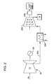
- FIG 2 is a schematic illustrating a system a portion of the system shown in Figure 1 in accordance with an embodiment of the present invention.
- compressed air from the gas turbine compressor 24 may be supplied to the ASU 14 through an intercooler 204 and a variable guide vane booster 208.
- high temperature compressed air may be channeled from the gas turbine compressor 24 through a first flow path 202 of an intercooler 204.
- a flow of cooling fluid may flow through a second flow path 206 through intercooler 204.
- the ASU 14 may use the compressed air to generate oxygen for use by the gasifier 16.
- the ASU 14 may separate the compressed air into separate flows of oxygen (O 2 ) and a gas by-product, sometimes referred to as a "process gas.”
- the compressed air supplied to ASU 14 may be bleed from the gas turbine compressor 24 and then maintained at a relatively constant pressure using the variable guide vane booster 208.
- the variable guide vane booster 208 may comprise at least one of: an axial booster, a centrifugal booster, and combinations thereof.
- an embodiment of the present invention may supply compressed air to combustor 26 and the ASU 14 from the gas turbine compressor 24.
- the pressure of the compressor bleed airflow discharged from the gas turbine compressor 24 is variable and is related to the load on the generator 34.
- the variable guide vane booster 208 may regulate an inlet pressure to the ASU 14 by modulating the speed of the variable guide vane booster 208 using the booster turbine 220.
- the variable guide vane booster 208 may also adjust the airflow to the ASU 14 by using a set of variable guide vanes, such that the airflow supplied to the ASU 14 is at a substantially constant pressure over a wide range of operating loads of the gas turbine 20.
- variable guide vane booster 208 may rotate at a variable speed to maintain a substantially constant outlet pressure.
- variable guide vane booster 208 may position the guide vanes to accommodate fluctuations in the flow due to the change in rotating speed and per airflow requirements of the ASU 14. The operation of the variable guide vane booster 208 permits a wide range of compressor bleed air flow and/or pressure due to changes in the load on the gas turbine 20 while maintaining a substantially constant outlet air pressure with a required amount of airflow at the inlet of the ASU 14.
- an external power source 240 may supply the energy that the variable guide vane booster 208 requires for operation.
- the external power source 240 may operate independently from the IGCC power plant 10.
- the external power source 240 may not require an energy source from the IGCC power plant 10.
- the external power source 240 may provide multiple benefits such as, but not limiting of, allowing the IGCC power plant 10 to utilize all the generated power for commercial and or economic benefits.
- the external power source 240 may also allowing for quicker operation of the variable guide vane booster 208.
- the start-up time of the external power source 240 may be considerably less than that of the aforementioned known systems.
- the external power source 240 may comprise: a gasoline engine, a diesel engine, or any type of internal combustion engine.
- the external power source 240 may be integrated with the variable guide vane booster 208 in a manner allowing for the external power source 240 to directly or indirectly power the variable guide vane booster 208.
- the external power source 240 may be mechanically coupled to the variable guide vane booster 208.
- a speed of the booster turbine 220 may determine a speed of the variable guide vane booster 208.
- the external power source 240 may be coupled with a motor 240.
- the operation of the external power source 240 may energize the motor 240, which may be electrically coupled to the variable guide vane booster 208.
- the motor 240 may provide power to the variable guide vane booster 208.
- the present invention may be embodied as a method, system, or computer program product. Accordingly, the present invention may take the form of an entirely hardware embodiment, an entirely software embodiment (including firmware, resident software, micro-code, etc.) or an embodiment combining software and hardware aspects all generally referred to herein as a "circuit", "module,” or “ system”. Furthermore, the present invention may take the form of a computer program product on a computer-usable storage medium having computer-usable program code embodied in the medium. As used herein, the terms "software” and “firmware” are interchangeable, and include any computer program stored in memory for execution by a processor, including RAM memory, ROM memory, EPROM memory, EEPROM memory, and non-volatile RAM (NVRAM) memory. The above memory types are exemplary only, and are thus not limiting as to the types of memory usable for storage of a computer program.
- the computer-usable or computer-readable medium may be, for example but not limited to, an electronic, magnetic, optical, electromagnetic, infrared, or semiconductor system, apparatus, device, or propagation medium. More specific examples (a non exhaustive list) of the computer-readable medium would include the following: an electrical connection having one or more wires, a portable computer diskette, a hard disk, a random access memory (RAM), a read-only memory (ROM), an erasable programmable read-only memory (EPROM or Flash memory), an optical fiber, a portable compact disc read-only memory (CD-ROM), an optical storage device, a transmission media such as those supporting the Internet or an intranet, or a magnetic storage device.
- the computer-usable or computer-readable medium could even be paper or another suitable medium upon which the program is printed, as the program can be electronically captured, via, for instance, optical scanning of the paper or other medium, then compiled, interpreted, or otherwise processed in a suitable manner, if necessary, and then stored in a computer memory.
- a computer-usable or computer-readable medium may be any medium that can contain, store, communicate, propagate, or transport the program for use by or in connection with the instruction execution system, apparatus, or device.
- processor refers to central processing units, microprocessors, microcontrollers, reduced instruction set circuits (RISC), application specific integrated circuits (ASIC), logic circuits, and any other circuit or processor capable of executing the functions described herein.
- RISC reduced instruction set circuits
- ASIC application specific integrated circuits
- Computer program code for carrying out operations of the present invention may be written in an object oriented programming language such as Java7, Smalltalk or C++, or the like. However, the computer program code for carrying out operations of the present invention may also be written in conventional procedural programming languages, such as the "C" programming language, or a similar language.
- the program code may execute entirely on the user's computer, partly on the user's computer, as a stand-alone software package, partly on the user's computer and partly on a remote computer or entirely on the remote computer. In the latter scenario, the remote computer may be connected to the user's computer through a local area network (LAN) or a wide area network (WAN), or the connection may be made to an external computer (for example, through the Internet using an Internet Service Provider).
- LAN local area network
- WAN wide area network
- Internet Service Provider for example, AT&T, MCI, Sprint, EarthLink, MSN, GTE, etc.
- These computer program instructions may also be stored in a computer-readable memory that can direct a computer or other programmable data processing apparatus to function in a particular manner, such that the instructions stored in the computer-readable memory produce an article of manufacture including instruction means which implement the function/act specified in the flowchart and/or block diagram block or blocks.
- the computer program instructions may also be loaded onto a computer or other programmable data processing apparatus to cause a series of operational steps to be performed on the computer or other programmable apparatus to produce a computer implemented process such that the instructions which execute on the computer or other programmable apparatus provide steps for implementing the functions/acts specified in the flowchart and/or block diagram blocks.
- the present invention may include a control system, or the like, that has the technical effect of controlling the operating of an IGCC power plant 10 integrated with an embodiment of the present invention.
- the control system of an embodiment of the present invention may be configured to automatically and/or continuously monitor the IGCC power plant 10 to determine whether the external power source 240 should operate.
- control system may be configured to require a user action to the initiate operation of the external power source 240.
- An embodiment of the control system of the present invention may function as a stand-alone system.
- control system may be integrated as a module, or the like, within a broader system, such as a turbine control or a plant control system.
- Figure 3 is a flowchart illustrating an example of a method of controlling a portion of the IGCC power plant 10, in accordance with an embodiment of the present invention.
- the method 300 may determine whether the gas turbine 20 is generating an exhaust.
- the method 300 may include this requirement as a permissive or like, prior to initiating the operating of the variable guide vane booster 208.
- the method 300 may initiate the operation of the external power source 240.
- the processor 242 may automatically initiate the operation.
- the processor 242 may provide a notification that operation of the external power source 240 may start.
- an operator may begin the start-up sequence of, and ensure the preparedness of, the external power source 240.
- the method 300 may couple the external power source 240 with the variable guide vane booster 208.
- the operator may mechanically, and/or electrically connect an output of the external power source 240 with an input of the variable guide vane booster 208.
- step 308 the energy from the external power source 240 may drive the variable guide vane booster 208, as described.
- the processor 242 may coordinate the operations of the external power source 240, the variable guide vane booster 208, and the ASU 14.
- the goal here may be to meet the operational needs of the ASU 14 and other components on the IGCC power plant 10.
- FIG. 4 is a block diagram of an exemplary system 400 of controlling a combined cycle power plant air in accordance with an embodiment of the present invention.
- the elements of the method 300 may be embodied in and performed by the system 400.
- the system 400 may include one or more user or client communication devices 402 or similar systems or devices (two are illustrated in Figure 4 ).
- Each communication device 402 may be for example, but not limited to, a computer system, a personal digital assistant, a cellular phone, or any device capable of sending and receiving an electronic message.
- the communication device 402 may include a system memory 404 or local file system.
- the system memory 404 may include for example, but is not limited to, a read only memory (ROM) and a random access memory (RAM).
- the ROM may include a basic input/output system (BIOS).
- BIOS may contain basic routines that help to transfer information between elements or components of the communication device 402.
- the system memory 404 may contain an operating system 406 to control overall operation of the communication device 402.
- the system memory 404 may also include a browser 408 or web browser.
- the system memory 404 may also include data structures 410 or computer-executable code for controlling a combined cycle power plant that may be similar or include elements of the method 300 in Figure 3 .
- the system memory 404 may further include a template cache memory 412, which may be used in conjunction with the method 400 in Figure 4 for controlling a combined cycle power plant.
- the communication device 402 may also include a processor or processing unit 414 to control operations of the other components of the communication device 402.
- the operating system 406, browser 408, and data structures 410 may be operable on the processing unit 414.
- the processing unit 414 may be coupled to the memory system 404 and other components of the communication device 402 by a system bus 416.
- the communication device 402 may also include multiple input devices (I/O), output devices or combination input/output devices 418. Each input/output device 418 may be coupled to the system bus 416 by an input/output interface (not shown in Figure 4 ).
- the input and output devices or combination I/O devices 418 permit a user to operate and interface with the communication device 402 and to control operation of the browser 408 and data structures 410 to access, operate and control the software to utilize a combined cycle power plant.
- the I/O devices 418 may include a keyboard and computer pointing device or the like to perform the operations discussed herein.
- the I/O devices 418 may also include for example, but are not limited to, disk drives, optical, mechanical, magnetic, or infrared input/output devices, modems or the like.
- the I/O devices 418 may be used to access a storage medium 420.
- the medium 420 may contain, store, communicate, or transport computer-readable or computer-executable instructions or other information for use by or in connection with a system, such as the communication devices 402.
- the communication device 402 may also include or be connected to other devices, such as a display or monitor 422.
- the monitor 422 may permit the user to interface with the communication device 402.
- the communication device 402 may also include a hard drive 424.
- the hard drive 424 may be coupled to the system bus 416 by a hard drive interface (not shown in Figure 4 ).
- the hard drive 424 may also form part of the local file system or system memory 404. Programs, software, and data may be transferred and exchanged between the system memory 404 and the hard drive 424 for operation of the communication device 402.
- the communication device 402 may communicate with at least one unit controller 426 and may access other servers or other communication devices similar to communication device 402 via a network 428.
- the system bus 416 may be coupled to the network 428 by a network interface 430.
- the network interface 430 may be a modem, Ethernet card, router, gateway, or the like for coupling to the network 428.
- the coupling may be a wired or wireless connection.
- the network 428 may be the Internet, private network, an intranet, or the like.
- the at least one unit controller 426 may also include a system memory 432 that may include a file system, ROM, RAM, and the like.
- the system memory 432 may include an operating system 434 similar to operating system 406 in communication devices 402.
- the system memory 432 may also include data structures 436 for controlling a combined cycle power plant.
- the data structures 436 may include operations similar to those described with respect to the method 300 for controlling a combined cycle power plant.
- the server system memory 432 may also include other files 438, applications, modules, and the like.
- the at least one unit controller 426 may also include a processor 442 or a processing unit to control operation of other devices in the at least one unit controller 426.
- the at least one unit controller 426 may also include I/O device 444.
- the I/O devices 444 may be similar to I/O devices 418 of communication devices 402.
- the at least one unit controller 426 may further include other devices 446, such as a monitor or the like to provide an interface along with the I/O devices 444 to the at least one unit controller 426.
- the at least one unit controller 426 may also include a hard disk drive 448.
- a system bus 450 may connect the different components of the at least one unit controller 426.
- a network interface 452 may couple the at least one unit controller 426 to the network 428 via the system bus 450.
- each step in the flowchart or step diagrams may represent a module, segment, or portion of code, which comprises one or more executable instructions for implementing the specified logical function(s).
- the functions noted in the step may occur out of the order noted in the figures. For example, two steps shown in succession may, in fact, be executed substantially concurrently, or the steps may sometimes be executed in the reverse order, depending upon the functionality involved.
- each step of the step diagrams and/or flowchart illustration, and combinations of steps in the step diagrams and/or flowchart illustration can be implemented by special purpose hardware-based systems which perform the specified functions or acts, or combinations of special purpose hardware and computer instructions.
Landscapes
- Engineering & Computer Science (AREA)
- Mechanical Engineering (AREA)
- General Engineering & Computer Science (AREA)
- Physics & Mathematics (AREA)
- Thermal Sciences (AREA)
- Chemical & Material Sciences (AREA)
- Combustion & Propulsion (AREA)
- Engine Equipment That Uses Special Cycles (AREA)
- Structures Of Non-Positive Displacement Pumps (AREA)
- Hydrogen, Water And Hydrids (AREA)
Abstract
Description
- This invention relates generally to power generation systems and, more particularly, to combined cycle power plants that include large variable speed process equipment.
- Some known integrated gasification combined cycle (IGCC) power plants use an air separation unit to generate a flow of oxidant for the gasification process. Generally, the air separation unit requires a source of relatively constant flow and pressure compressed air. A motor driven compressor is typically used for providing the compressed air at the necessary flow and pressure. However, the motor driven compressor is an expensive piece of equipment that uses significant electrical power. Furthermore, the motor driven compressor may be considered a parasitic load on the IGCC power plant, leading to a reduction in the overall efficiency.
- Another source of air for the air processing unit is the compressor of the gas turbine associated with the IGCC power plant. However, the air provided by the compressor is at variable pressure and flows based on a load on the gas turbine.
- Some known systems incorporate an apparatus that receives the air at variable pressure from the compressor and discharges the air at a nearly constant pressure. Typically, the apparatus is driven and/or energized by a turbine integrated with the IGCC power plant. This turbine may be considered a dependent energy source since the turbine is driven and/or energized by a component of the IGCC power plant. For example, but not limiting of, the turbine may comprise a steam turbine that receives steam from a heat recovery steam generator (HRSG) of the IGCC power plant. However, extracting the steam from the HRSG may not be economically preferred or commercially allowable. The operator of the IGCC power generation power plant may be able to receive higher revenue from the extracted steam. Furthermore, the operator may be contractually obligated to provide a certain amount of steam to a process.
- For the foregoing reasons, there is a need for a system and method providing a source of relatively constant flow and pressure compressed air to an air processing unit. The system and method should not be a parasitic load on the IGCC power plant. The system and method should provide a source of relatively constant pressure and adjustable flow of compressed air across a load range of the gas turbine. The system and method should use an independent energy source to drive and/or energize the apparatus that receives the air at variable pressure from the compressor and discharges the air at a nearly constant pressure.
- In accordance with an embodiment of the present invention there is provided a combined cycle powerplant system comprising: a gas turbine comprising: a compressor, a combustion chamber, and a turbine section drivingly coupled to the compressor; a source of bleed air from the compressor coupled in flow communication with an inlet of a variable guide vane booster; an external power source; an air separation unit coupled in flow communication with an outlet of the variable guide vane booster, the variable guide vane booster integrated with the external power source, wherein the external power source powers the variable guide vane booster to operate.
- In accordance with an alternate embodiment of the present invention there is provided an integrated gasification combined cycle (IGCC) power plant comprising: a gas turbine comprising: a compressor, a combustion chamber, and a turbine section drivingly coupled to the compressor; an external power source; and a variable guide vane booster coupled in flow communication between the compressor and an air separation unit, the variable guide vane booster configured to receive a flow of compressed air at a variable flow and pressure and to generate a flow of compressed air at a flow that matches a demand using one or more variable vanes and a substantially constant pressure to the air separation unit, the variable guide vane booster drivingly coupled to the external power source.
- There follows a detailed description of embodiments of the invention by way of example only with reference to the accompanying drawings, in which:
-
Figure 1 is a schematic illustrating a known integrated gasification combined-cycle (IGCC) power generation system; -
Figure 2 is a schematic illustrating a portion of the system shown inFigure 1 , in accordance with an embodiment of the present invention; -
Figure 3 is a flowchart illustrating a method of controlling a portion of the IGCC system, in accordance with an embodiment of the present invention; and -
Figure 4 is a block diagram of an exemplary system for operating a combined cycle power plant in accordance with an embodiment of the present invention. - The following detailed description of preferred embodiments refers to the accompanying drawings, which illustrate specific embodiments of the invention. Other embodiments having different structures and operations do not depart from the scope of the present invention.
- Certain terminology is used herein for the convenience of the reader only and is not to be taken as a limitation on the scope of the invention. For example, words such as "upper", "lower", "left", "right", "front", "rear", "top", "bottom", "horizontal", "vertical", "upstream", "downstream", "fore", "aft", and the like; merely describe the configuration shown in the Figures. Indeed, the element or elements of an embodiment of the present invention may be oriented in any direction and the terminology, therefore, should be understood as encompassing such variations unless specified otherwise.
- As used herein, an element or step recited in the singular and proceeded with the word "a" or "an" should be understood as not excluding plural elements or steps, unless such exclusion is explicitly recited. Furthermore, references to "one embodiment" of the present invention are not intended to be interpreted as excluding the existence of additional embodiments that also incorporate the recited features.
- An embodiment of the present invention may provide a variable speed booster, which receives air from a compressor of a gas turbine through an intercooler, to supply air at a relatively constant pressure to an air processing unit. An embodiment of the present invention may provide an external power source to energize a variable speed booster; which provides air at a relatively constant pressure to an air processing unit.
- Referring now to the Figures, wherein the various numbers represent like elements throughout the several views,
Figure 1 is a schematic diagram of a known integrated gasification combined-cycle (IGCC)power generation system 10. IGCCpower plant 10 generally includes a main air acompressor 12, an air separation unit (ASU) 14 coupled in flow communication to thecompressor 12, agasifier 16 coupled in flow communication to theASU 14, asyngas cooler 18 coupled in flow communication to agasifier 16, agas turbine 20 coupled in flow communication to thesyngas cooler 18, and asteam turbine 22 coupled in flow communication to thesyngas cooler 18. In some IGCCpower generation systems 10, thegasifier 16 and thesyngas cooler 18 may be combined into a single integral vessel. - In operation, the
compressor 12 compresses ambient air that may then be channeled to the ASU 14. In some IGCCpower generation systems 10, compressed air from agas turbine compressor 24 may also be channeled to the ASU 14. Alternatively, compressed air from thegas turbine compressor 24 is supplied to the ASU 14, rather than compressed air from thecompressor 12 being supplied to the ASU 14. Here, the ASU 14 may use the compressed air to generate oxygen for use by thegasifier 16. More specifically, the ASU 14 separates the compressed air into separate flows of oxygen (O2) and a gas by-product, sometimes referred to as a "process gas." The O2 flow is channeled to thegasifier 16 for use in generating partially combusted gases, referred to herein as "syngas" for use by thegas turbine 20 as fuel, as further described below. - The process gas generated by the
ASU 14 includes nitrogen and will be referred to herein as "nitrogen process gas" (NPG). The NPG may also include other gases such as, but not limited to, oxygen and/or argon. For example, the NPG may include between about 95% and about 100% nitrogen. In some IGCCpower generation systems 10, at least some of the NPG flow is vented to the atmosphere from the ASU 14. Some of the NPG flow is injected into a combustion zone (not shown) within agas turbine combustor 26 to facilitate controlling emissions ofengine 20. This may facilitate reducing the combustion temperature and reducing nitrous oxide emissions fromgas turbine 20. In some IGCCpower generation systems 10, acompressor 28 may be used for compressing the NPG flow before injection into the combustion zone of thegas turbine combustor 26. - In some IGCC
power generation systems 10, thegasifier 16 converts a mixture of fuel supplied from afuel supply 30, O2 supplied by the ASU 14, steam, and/or limestone into an output of syngas for use as fuel by thegas turbine 20 as fuel. Although thegasifier 16 may use any fuel, an embodiment of thegasifier 16, may use coal, petroleum coke, residual oil, oil emulsions, tar sands, and/or other similar fuels. Furthermore, in some IGCCpower generation systems 10, the syngas generated by thegasifier 16 includes carbon dioxide. Thegasifier 16 may comprise the form of a fixed-bed gasifier, a fluidized-bed gasifier, and/or a fully entrained gasifier. - In some IGCC
power generation systems 10, syngas generated by thegasifier 16 is channeled to thesyngas cooler 18 to facilitate cooling syngas, as described in more detail below. The cooled syngas is channeled from thesyngas cooler 18 to a clean-updevice 32 for cleaning the syngas before the syngas is channeled to thegas turbine combustor 26 for combustion purposes. Carbon dioxide (CO2) may be separated from the syngas during clean-up and may be vented to the atmosphere. Thegas turbine 20 drives agenerator 34 that supplies electrical power to a power grid (not illustrated). Exhaust gases from thegas turbine 20 may be channeled to a heat recovery steam generator (HRSG) 36 that generates steam for driving asteam turbine 22. Power generated by thesteam turbine 22 may drive anelectrical generator 38 that provides electrical power to the power grid. In some IGCCpower generation systems 10, steam from theHRSG 36 is supplied to thegasifier 16 for generating syngas. - When starting the
gas turbine 20, astarter 35 such as a load-commutated inverter (LCI) or static-frequency converter (SFC) may receive an AC electrical power from apower system bus 37, via acircuit breaker 42 and apower transformer 44.Starter 35 rectifies the AC power to DC power, then inverts the DC power into AC power having a variable AC frequency to supply to agenerator 34 viadisconnect switch 46. Thegenerator 34 is operated as a synchronous motor to provide a torque control necessary for thegas turbine 20 to start. When thegas turbine 20 attains a self-sustaining, aspeed disconnect switch 46 is opened to isolatestarter 35 from thegenerator 34.Circuit breaker 42 is also opened to cut off power supply frompower system bus 37. Astarter controller 48 receives various sensing and command signals, and serves to regulate the operation of thegenerator 34, functioning as a motor during startup of thegas turbine 20. Astarter 35 provides for adjustable speed operation and soft starting of thegenerator 34. Generally, soft starting reduces the mechanical stress on thegenerator 34 and thegas turbine 20 and facilitates eliminating electrical starting surges on theAC power system 37. An output transformer permits thestarter 35 to operate with any voltage machine. - Furthermore, in some IGCC power generation systems 10 a
pump 40 may supply boiled water from theHRSG 36 to thesyngas cooler 18 to facilitate cooling the syngas channeled from thegasifier 16. The boiled water may be channeled through thesyngas cooler 18 wherein the water is converted to steam. The steam from thesyngas cooler 18 and then returned to theHRSG 36 for use within thegasifier 16, thesyngas cooler 18, and/or thesteam turbine 22. -
Figure 2 is a schematic illustrating a system a portion of the system shown inFigure 1 in accordance with an embodiment of the present invention. In an embodiment of the present invention, compressed air from thegas turbine compressor 24 may be supplied to theASU 14 through an intercooler 204 and a variableguide vane booster 208. Here, high temperature compressed air may be channeled from thegas turbine compressor 24 through afirst flow path 202 of an intercooler 204. A flow of cooling fluid may flow through asecond flow path 206 through intercooler 204. TheASU 14 may use the compressed air to generate oxygen for use by thegasifier 16. More specifically, theASU 14 may separate the compressed air into separate flows of oxygen (O2) and a gas by-product, sometimes referred to as a "process gas." To facilitate increasing the overall efficiency ofsystem 10, the compressed air supplied toASU 14 may be bleed from thegas turbine compressor 24 and then maintained at a relatively constant pressure using the variableguide vane booster 208. The variableguide vane booster 208 may comprise at least one of: an axial booster, a centrifugal booster, and combinations thereof. - In use, an embodiment of the present invention may supply compressed air to
combustor 26 and theASU 14 from thegas turbine compressor 24. The pressure of the compressor bleed airflow discharged from thegas turbine compressor 24 is variable and is related to the load on thegenerator 34. Instead of channeling the variable pressure compressor bleed airflow directly to theASU 14, the variableguide vane booster 208 may regulate an inlet pressure to theASU 14 by modulating the speed of the variableguide vane booster 208 using the booster turbine 220. The variableguide vane booster 208 may also adjust the airflow to theASU 14 by using a set of variable guide vanes, such that the airflow supplied to theASU 14 is at a substantially constant pressure over a wide range of operating loads of thegas turbine 20. - To regulate the pressure of the airflow directed to the
ASU 14, the variableguide vane booster 208 may rotate at a variable speed to maintain a substantially constant outlet pressure. To modulate airflow of the compressed air flowing from thegas turbine compressor 24 to theASU 14, the variableguide vane booster 208 may position the guide vanes to accommodate fluctuations in the flow due to the change in rotating speed and per airflow requirements of theASU 14. The operation of the variableguide vane booster 208 permits a wide range of compressor bleed air flow and/or pressure due to changes in the load on thegas turbine 20 while maintaining a substantially constant outlet air pressure with a required amount of airflow at the inlet of theASU 14. - In an embodiment of the present invention, an
external power source 240 may supply the energy that the variableguide vane booster 208 requires for operation. Theexternal power source 240 may operate independently from theIGCC power plant 10. Theexternal power source 240 may not require an energy source from theIGCC power plant 10. Theexternal power source 240 may provide multiple benefits such as, but not limiting of, allowing theIGCC power plant 10 to utilize all the generated power for commercial and or economic benefits. Theexternal power source 240 may also allowing for quicker operation of the variableguide vane booster 208. Here, the start-up time of theexternal power source 240 may be considerably less than that of the aforementioned known systems. - The
external power source 240 may comprise: a gasoline engine, a diesel engine, or any type of internal combustion engine. Theexternal power source 240 may be integrated with the variableguide vane booster 208 in a manner allowing for theexternal power source 240 to directly or indirectly power the variableguide vane booster 208. For example, but not limiting of, theexternal power source 240 may be mechanically coupled to the variableguide vane booster 208. Here a speed of the booster turbine 220 may determine a speed of the variableguide vane booster 208. - Alternatively, the
external power source 240 may be coupled with amotor 240. Here, the operation of theexternal power source 240 may energize themotor 240, which may be electrically coupled to the variableguide vane booster 208. Here, themotor 240 may provide power to the variableguide vane booster 208. - As will be appreciated, the present invention may be embodied as a method, system, or computer program product. Accordingly, the present invention may take the form of an entirely hardware embodiment, an entirely software embodiment (including firmware, resident software, micro-code, etc.) or an embodiment combining software and hardware aspects all generally referred to herein as a "circuit", "module," or " system". Furthermore, the present invention may take the form of a computer program product on a computer-usable storage medium having computer-usable program code embodied in the medium. As used herein, the terms "software" and "firmware" are interchangeable, and include any computer program stored in memory for execution by a processor, including RAM memory, ROM memory, EPROM memory, EEPROM memory, and non-volatile RAM (NVRAM) memory. The above memory types are exemplary only, and are thus not limiting as to the types of memory usable for storage of a computer program.
- Any suitable computer readable medium may be utilized. The computer-usable or computer-readable medium may be, for example but not limited to, an electronic, magnetic, optical, electromagnetic, infrared, or semiconductor system, apparatus, device, or propagation medium. More specific examples (a non exhaustive list) of the computer-readable medium would include the following: an electrical connection having one or more wires, a portable computer diskette, a hard disk, a random access memory (RAM), a read-only memory (ROM), an erasable programmable read-only memory (EPROM or Flash memory), an optical fiber, a portable compact disc read-only memory (CD-ROM), an optical storage device, a transmission media such as those supporting the Internet or an intranet, or a magnetic storage device. Note that the computer-usable or computer-readable medium could even be paper or another suitable medium upon which the program is printed, as the program can be electronically captured, via, for instance, optical scanning of the paper or other medium, then compiled, interpreted, or otherwise processed in a suitable manner, if necessary, and then stored in a computer memory. In the context of this document, a computer-usable or computer-readable medium may be any medium that can contain, store, communicate, propagate, or transport the program for use by or in connection with the instruction execution system, apparatus, or device.
- The term processor, as used herein, refers to central processing units, microprocessors, microcontrollers, reduced instruction set circuits (RISC), application specific integrated circuits (ASIC), logic circuits, and any other circuit or processor capable of executing the functions described herein.
- Computer program code for carrying out operations of the present invention may be written in an object oriented programming language such as Java7, Smalltalk or C++, or the like. However, the computer program code for carrying out operations of the present invention may also be written in conventional procedural programming languages, such as the "C" programming language, or a similar language. The program code may execute entirely on the user's computer, partly on the user's computer, as a stand-alone software package, partly on the user's computer and partly on a remote computer or entirely on the remote computer. In the latter scenario, the remote computer may be connected to the user's computer through a local area network (LAN) or a wide area network (WAN), or the connection may be made to an external computer (for example, through the Internet using an Internet Service Provider).
- The present invention is described below with reference to flowchart illustrations and/or block diagrams of methods, apparatuses (systems) and computer program products according to embodiments of the invention. It will be understood that each block of the flowchart illustrations and/or block diagrams, and combinations of blocks in the flowchart illustrations and/or block diagrams, can be implemented by computer program instructions. These computer program instructions may be provided to a processor of a public purpose computer, special purpose computer, or other programmable data processing apparatus to produce a machine, such that the instructions, which execute via the processor of the computer or other programmable data processing apparatus, create means for implementing the functions/acts specified in the flowchart and/or block diagram block or blocks.
- These computer program instructions may also be stored in a computer-readable memory that can direct a computer or other programmable data processing apparatus to function in a particular manner, such that the instructions stored in the computer-readable memory produce an article of manufacture including instruction means which implement the function/act specified in the flowchart and/or block diagram block or blocks. The computer program instructions may also be loaded onto a computer or other programmable data processing apparatus to cause a series of operational steps to be performed on the computer or other programmable apparatus to produce a computer implemented process such that the instructions which execute on the computer or other programmable apparatus provide steps for implementing the functions/acts specified in the flowchart and/or block diagram blocks.
- The present invention may include a control system, or the like, that has the technical effect of controlling the operating of an
IGCC power plant 10 integrated with an embodiment of the present invention. The control system of an embodiment of the present invention may be configured to automatically and/or continuously monitor theIGCC power plant 10 to determine whether theexternal power source 240 should operate. - Alternatively, the control system may be configured to require a user action to the initiate operation of the
external power source 240. An embodiment of the control system of the present invention may function as a stand-alone system. Alternatively, the control system may be integrated as a module, or the like, within a broader system, such as a turbine control or a plant control system. -
Figure 3 is a flowchart illustrating an example of a method of controlling a portion of theIGCC power plant 10, in accordance with an embodiment of the present invention. - In
step 302, themethod 300 may determine whether thegas turbine 20 is generating an exhaust. Here, themethod 300 may include this requirement as a permissive or like, prior to initiating the operating of the variableguide vane booster 208. - In
step 304, themethod 300 may initiate the operation of theexternal power source 240. In an embodiment of the present invention, theprocessor 242 may automatically initiate the operation. Alternatively, theprocessor 242 may provide a notification that operation of theexternal power source 240 may start. Here, an operator may begin the start-up sequence of, and ensure the preparedness of, theexternal power source 240. - In
step 306, themethod 300 may couple theexternal power source 240 with the variableguide vane booster 208. Here, for example, but not limiting of, the operator may mechanically, and/or electrically connect an output of theexternal power source 240 with an input of the variableguide vane booster 208. - In
step 308, the energy from theexternal power source 240 may drive the variableguide vane booster 208, as described. Here, theprocessor 242 may coordinate the operations of theexternal power source 240, the variableguide vane booster 208, and theASU 14. The goal here may be to meet the operational needs of theASU 14 and other components on theIGCC power plant 10. -
Figure 4 is a block diagram of anexemplary system 400 of controlling a combined cycle power plant air in accordance with an embodiment of the present invention. The elements of themethod 300 may be embodied in and performed by thesystem 400. Thesystem 400 may include one or more user orclient communication devices 402 or similar systems or devices (two are illustrated inFigure 4 ). Eachcommunication device 402 may be for example, but not limited to, a computer system, a personal digital assistant, a cellular phone, or any device capable of sending and receiving an electronic message. - The
communication device 402 may include asystem memory 404 or local file system. Thesystem memory 404 may include for example, but is not limited to, a read only memory (ROM) and a random access memory (RAM). The ROM may include a basic input/output system (BIOS). The BIOS may contain basic routines that help to transfer information between elements or components of thecommunication device 402. Thesystem memory 404 may contain anoperating system 406 to control overall operation of thecommunication device 402. Thesystem memory 404 may also include abrowser 408 or web browser. Thesystem memory 404 may also includedata structures 410 or computer-executable code for controlling a combined cycle power plant that may be similar or include elements of themethod 300 inFigure 3 . - The
system memory 404 may further include atemplate cache memory 412, which may be used in conjunction with themethod 400 inFigure 4 for controlling a combined cycle power plant. - The
communication device 402 may also include a processor orprocessing unit 414 to control operations of the other components of thecommunication device 402. Theoperating system 406,browser 408, anddata structures 410 may be operable on theprocessing unit 414. Theprocessing unit 414 may be coupled to thememory system 404 and other components of thecommunication device 402 by asystem bus 416. Thecommunication device 402 may also include multiple input devices (I/O), output devices or combination input/output devices 418. Each input/output device 418 may be coupled to thesystem bus 416 by an input/output interface (not shown inFigure 4 ). The input and output devices or combination I/O devices 418 permit a user to operate and interface with thecommunication device 402 and to control operation of thebrowser 408 anddata structures 410 to access, operate and control the software to utilize a combined cycle power plant. The I/O devices 418 may include a keyboard and computer pointing device or the like to perform the operations discussed herein. - The I/
O devices 418 may also include for example, but are not limited to, disk drives, optical, mechanical, magnetic, or infrared input/output devices, modems or the like. The I/O devices 418 may be used to access astorage medium 420. The medium 420 may contain, store, communicate, or transport computer-readable or computer-executable instructions or other information for use by or in connection with a system, such as thecommunication devices 402. - The
communication device 402 may also include or be connected to other devices, such as a display or monitor 422. Themonitor 422 may permit the user to interface with thecommunication device 402. - The
communication device 402 may also include ahard drive 424. Thehard drive 424 may be coupled to thesystem bus 416 by a hard drive interface (not shown inFigure 4 ). Thehard drive 424 may also form part of the local file system orsystem memory 404. Programs, software, and data may be transferred and exchanged between thesystem memory 404 and thehard drive 424 for operation of thecommunication device 402. - The
communication device 402 may communicate with at least oneunit controller 426 and may access other servers or other communication devices similar tocommunication device 402 via anetwork 428. Thesystem bus 416 may be coupled to thenetwork 428 by anetwork interface 430. Thenetwork interface 430 may be a modem, Ethernet card, router, gateway, or the like for coupling to thenetwork 428. The coupling may be a wired or wireless connection. Thenetwork 428 may be the Internet, private network, an intranet, or the like. - The at least one
unit controller 426 may also include asystem memory 432 that may include a file system, ROM, RAM, and the like. Thesystem memory 432 may include anoperating system 434 similar tooperating system 406 incommunication devices 402. Thesystem memory 432 may also includedata structures 436 for controlling a combined cycle power plant. Thedata structures 436 may include operations similar to those described with respect to themethod 300 for controlling a combined cycle power plant. Theserver system memory 432 may also includeother files 438, applications, modules, and the like. - The at least one
unit controller 426 may also include aprocessor 442 or a processing unit to control operation of other devices in the at least oneunit controller 426. The at least oneunit controller 426 may also include I/O device 444. The I/O devices 444 may be similar to I/O devices 418 ofcommunication devices 402. The at least oneunit controller 426 may further includeother devices 446, such as a monitor or the like to provide an interface along with the I/O devices 444 to the at least oneunit controller 426. The at least oneunit controller 426 may also include ahard disk drive 448. Asystem bus 450 may connect the different components of the at least oneunit controller 426. Anetwork interface 452 may couple the at least oneunit controller 426 to thenetwork 428 via thesystem bus 450. - The flowcharts and step diagrams in the figures illustrate the architecture, functionality, and operation of possible implementations of systems, methods, and computer program products according to various embodiments of the present invention. In this regard, each step in the flowchart or step diagrams may represent a module, segment, or portion of code, which comprises one or more executable instructions for implementing the specified logical function(s). It should also be noted that, in some alternative implementations, the functions noted in the step may occur out of the order noted in the figures. For example, two steps shown in succession may, in fact, be executed substantially concurrently, or the steps may sometimes be executed in the reverse order, depending upon the functionality involved. It will also be noted that each step of the step diagrams and/or flowchart illustration, and combinations of steps in the step diagrams and/or flowchart illustration, can be implemented by special purpose hardware-based systems which perform the specified functions or acts, or combinations of special purpose hardware and computer instructions.
- The terminology used herein is for the purpose of describing particular embodiments only and is not intended to be limiting of the invention. As used herein, the singular forms "a", "an" and "the" are intended to include the plural forms as well, unless the context clearly indicates otherwise. It will be further understood that the terms "comprises" and/or "comprising," when used in this specification, specify the presence of stated features, integers, steps, operations, elements, and/or components, but do not preclude the presence or addition of one or more other features, integers, steps, operations, elements, components, and/or groups thereof.
- Although specific embodiments have been illustrated and described herein, it should be appreciated that any arrangement, which is calculated to achieve the same purpose, may be substituted for the specific embodiments shown and that the invention has other applications in other environments. This application is intended to cover any adaptations or variations of the present invention. The following claims are in no way intended to limit the scope of the invention to the specific embodiments described herein.
- For completeness, various aspects of the invention are now set out in the following numbered clauses:
- 1. A combined cycle powerplant system comprising:
- a gas turbine comprising: a compressor, a combustion chamber, and a turbine section drivingly coupled to the compressor;
- a source of bleed air from the compressor coupled in flow communication with an inlet of a variable guide vane booster;
- an external power source;
- an air separation unit coupled in flow communication with an outlet of the variable guide vane booster, the variable guide vane booster integrated with the external power source, wherein the external power source powers the variable guide vane booster to operate.
- 2. The system of
clause 1, wherein the external power source comprises at least one of: a gasoline engine, a diesel engine, or an internal combustion engine. - 3. The system of
clause 1, wherein the external power source is mechanically coupled to the variable guide vane booster and the external power source determines a speed of the variable speed booster. - 4. The system of
clause 1, wherein the variable guide vane booster comprises at least one row of variable guide vanes and is configured to modulate a flow through the variable guide vane booster. - 5. The system of clause 0, wherein the variable guide vane booster comprises at least one of: an axial booster, a centrifugal booster, and combinations thereof.
- 6. The system of
clause 1, wherein the external power source is drivingly coupled to the variable guide vane booster, wherein the variable guide vane booster is configured to deliver a flow of compressed air at a substantially constant pressure to the air separation unit using the external power source to control a rotational speed of the variable guide vane booster. - 7. The system of
clause 1, further comprising a motor coupled to the external power source wherein the external power source energizes the motor; and wherein the motor energizes the variable guide vane booster. - 8. The system of
clause 1, wherein the external power source and the variable guide vane booster are integrated with an IGCC power plant. - 9. A method of operating a combined cycle powerplant system, the method comprising:
- providing a gas turbine comprising a compressor, wherein the gas turbine generates an exhaust;
- coupling a source of bleed air deriving from the compressor with an inlet of a variable guide vane booster; and
- coupling an outlet of the variable guide vane booster with an air separation unit, and utilizing an external power source to energize the variable guide vane booster.
- 10. The method of clause 9, further comprising configuring the compressor to supply a flow of compressed air to the air separation unit; the method further comprising utilizing the external power source to maintain a flow of compressed air that approximates the demand at a substantially constant pressure to the air separation unit coupled in flow communication with the compressor.
- 11. The method of
clause 10, further comprising mechanically coupling the variable guide vane booster to the external power source. - 12. The method of
clause 10, further comprising coupling a motor to the external power source, utilizing the external power source to energize the motor; and utilizing the motor to energize the variable guide vane booster. - 13. The method of
clause 10, further comprising the steps of:- determining whether the gas turbine is generating an exhaust;
- initiating the operation of the external power source;
- coupling the external power source with the variable guide vane booster; and
- utilizing the external power source to drive the variable guide vane booster.
- 14. An integrated gasification combined cycle (IGCC) power plant comprising:
- a gas turbine comprising: a compressor, a combustion chamber, and a turbine section drivingly coupled to the compressor;
- an external power source; and
- a variable guide vane booster coupled in flow communication between the compressor and an air separation unit, the variable guide vane booster configured to receive a flow of compressed air at a variable flow and pressure and to generate a flow of compressed air at a flow that matches a demand using one or more variable vanes and a substantially constant pressure to the air separation unit, the variable guide vane booster drivingly coupled to the external power source.
- 15. The IGCC power plant of
clause 14, further comprising a gasification vessel configured to receive a flow of fuel and a flow of an oxidant, the gasification vessel configured to partially oxidize the flow of fuel using the flow of oxidant to generate a synthetic gas. - 16. The IGCC power plant of
clause 14, wherein the external power source comprises a controller, wherein the controller comprises a processor configured to operate the external power source and the variable guide vane booster. - 17. The IGCC power plant of
clause 14, wherein the controller is configured to:- receive signals relating to operating parameters of at least one of; the gas turbine and the variable guide vane booster; and
- transmit command signals to the external power source such that the external power source is controlled to provide a flow that matches a demand of the air separation unit and a substantially constant pressure to the air separation unit.
- 18. The IGCC power plant of
clause 14, further comprising an intercooler coupled in flow communication between the compressor and the variable guide vane booster, wherein the intercooler is configured to reduce a temperature of the flow of compressed air deriving the compressor. - 19. The IGCC power plant of
clause 14, further comprising a motor coupled to the external power source. - 20. The IGCC power plant of clause 19, wherein the external power source energizes the motor.
- 21. The IGCC power plant of
clause 20, wherein the motor energizes the variable guide vane booster.
Claims (15)
- A combined cycle powerplant system comprising:a gas turbine (20) comprising: a compressor (28), a combustion chamber, and a turbine section drivingly coupled to the compressor (28);a source of bleed air from the compressor (28) coupled in flow communication with an inlet of a variable guide vane booster (208);an external power source (240);an air separation unit (14) coupled in flow communication with an outlet of the variable guide vane booster (208), the variable guide vane booster (208) integrated with the external power source (240), wherein the external power source (240) powers the variable guide vane booster (208) to operate.
- The system of claim 1, wherein the external power source (240) comprises at least one of: a gasoline engine, a diesel engine, or an internal combustion engine.
- The system of claim 1 or 2, wherein the external power source (240) is mechanically coupled to the variable guide vane booster (208) and the external power source (240) determines a speed of the variable speed booster (208).
- The system of any of the preceding claims, wherein the variable guide vane booster (208) comprises at least one row of variable guide vanes and is configured to modulate a flow through the variable guide vane booster (208).
- The system of any of the preceding claims, wherein the variable guide vane booster (208) comprises at least one of: an axial booster, a centrifugal booster, and combinations thereof.
- The system of any of the preceding claims, wherein the external power source (240) is drivingly coupled to the variable guide vane booster (208), wherein the variable guide vane booster (208) is configured to deliver a flow of compressed air at a substantially constant pressure to the air separation unit (140 using the external power source (240) to control a rotational speed of the variable guide vane booster (208).
- The system of any of the preceding claims, further comprising a motor (244) coupled to the external power source (240) wherein the external power source (240) energizes the motor (244); and wherein the motor (244) energizes the variable guide vane booster (208).
- The system of any of the preceding claims, wherein the external power source (240) and the variable guide vane booster (208) are integrated with an IGCC power plant (10).
- An integrated gasification combined cycle (IGCC) power plant (10) comprising:a gas turbine (20) comprising: a compressor (28), a combustion chamber, and a turbine section drivingly coupled to the compressor (28);an external power source (240); anda variable guide vane booster (208) coupled in flow communication between the compressor (28) and an air separation unit (140), the variable guide vane booster (208) configured to receive a flow of compressed air at a variable flow and pressure and to generate a flow of compressed air at a flow that matches a demand using one or more variable vanes and a substantially constant pressure to the air separation unit, the variable guide vane booster (208) drivingly coupled to the external power source (240).
- The IGCC power plant (10) of claim 9, further comprising a gasification vessel configured to receive a flow of fuel and a flow of an oxidant, the gasification vessel configured to partially oxidize the flow of fuel using the flow of oxidant to generate a synthetic gas.
- A method of operating a combined cycle powerplant system, the method comprising:providing a gas turbine comprising a compressor, wherein the gas turbine generates an exhaust;coupling a source of bleed air deriving from the compressor with an inlet of a variable guide vane booster; andcoupling an outlet of the variable guide vane booster with an air separation unit, and utilizing an external power source to energize the variable guide vane booster.
- The method of claim 11, further comprising configuring the compressor to supply a flow of compressed air to the air separation unit; the method further comprising utilizing the external power source to maintain a flow of compressed air that approximates the demand at a substantially constant pressure to the air separation unit coupled in flow communication with the compressor.
- The method of claim 11 or 12, further comprising mechanically coupling the variable guide vane booster to the external power source.
- The method of any of claims 11 to 13, further comprising coupling a motor to the external power source, utilizing the external power source to energize the motor; and utilizing the motor to energize the variable guide vane booster.
- The method of any of claims 11 to 14, further comprising the steps of:determining whether the gas turbine is generating an exhaust;initiating the operation of the external power source;coupling the external power source with the variable guide vane booster; andutilizing the external power source to drive the variable guide vane booster.
Applications Claiming Priority (1)
| Application Number | Priority Date | Filing Date | Title |
|---|---|---|---|
| US12/341,249 US7980083B2 (en) | 2008-12-22 | 2008-12-22 | Method and system for operating a combined cycle power plant |
Publications (2)
| Publication Number | Publication Date |
|---|---|
| EP2339133A1 true EP2339133A1 (en) | 2011-06-29 |
| EP2339133B1 EP2339133B1 (en) | 2016-03-23 |
Family
ID=42264105
Family Applications (1)
| Application Number | Title | Priority Date | Filing Date |
|---|---|---|---|
| EP09178314.2A Not-in-force EP2339133B1 (en) | 2008-12-22 | 2009-12-08 | Method and system for operating a combined cycle power plant |
Country Status (4)
| Country | Link |
|---|---|
| US (1) | US7980083B2 (en) |
| EP (1) | EP2339133B1 (en) |
| JP (1) | JP2010144720A (en) |
| CN (1) | CN101825016B (en) |
Families Citing this family (7)
| Publication number | Priority date | Publication date | Assignee | Title |
|---|---|---|---|---|
| US8069672B2 (en) * | 2008-12-22 | 2011-12-06 | General Electric Company | Method and systems for operating a combined cycle power plant |
| JP5631143B2 (en) | 2010-10-05 | 2014-11-26 | 株式会社日立製作所 | CO2 separation and recovery device and coal gasification combined cycle plant equipped with CO2 separation and recovery device |
| US20130257054A1 (en) * | 2012-03-29 | 2013-10-03 | General Electric Company | Gas Turbine - Variable Frequency Transformer Power Systems and Methods |
| US9481838B2 (en) | 2012-06-18 | 2016-11-01 | General Electric Company | Capture and storage of emissions from a gasifier |
| US20140130478A1 (en) * | 2012-11-09 | 2014-05-15 | General Electric Company | Gas turbomachine including a fuel pre-heat system |
| EP2808501A1 (en) * | 2013-05-27 | 2014-12-03 | Siemens Aktiengesellschaft | Method for operating a combined cycle power plant assembly |
| US10794272B2 (en) | 2018-02-19 | 2020-10-06 | General Electric Company | Axial and centrifugal compressor |
Citations (6)
| Publication number | Priority date | Publication date | Assignee | Title |
|---|---|---|---|---|
| EP0447122A1 (en) * | 1990-03-12 | 1991-09-18 | Hitachi, Ltd. | Pressurized fluidized bed combustion combined cycle power plant and method of operating the same |
| US20020088236A1 (en) * | 2001-01-11 | 2002-07-11 | General Electric Company | Method and apparatus for controlling nitrogen injection into gas turbine |
| US6430915B1 (en) * | 2000-08-31 | 2002-08-13 | Siemens Westinghouse Power Corporation | Flow balanced gas turbine power plant |
| US20080295480A1 (en) * | 2007-05-30 | 2008-12-04 | Mitsubishi Heavy Industries, Ltd. | Integrated gasification combined cycle power generation plant |
| WO2009064584A1 (en) * | 2007-11-16 | 2009-05-22 | General Electric Company | Methods for fabricating syngas cooler platens and syngas cooler platens |
| US20100019496A1 (en) * | 2008-07-28 | 2010-01-28 | Ping Yu | Method and systems for operating a combined cycle power plant |
Family Cites Families (7)
| Publication number | Priority date | Publication date | Assignee | Title |
|---|---|---|---|---|
| US4442665A (en) * | 1980-10-17 | 1984-04-17 | General Electric Company | Coal gasification power generation plant |
| FI941141A7 (en) * | 1993-03-15 | 1994-09-16 | Mitsubishi Heavy Ind Ltd | Energy generator based on coal gasification |
| GB9425484D0 (en) * | 1994-12-16 | 1995-02-15 | Boc Group Plc | Air separation |
| JP2001221058A (en) * | 2000-02-10 | 2001-08-17 | Hitachi Ltd | Gasification combined cycle power plant |
| US6568207B1 (en) * | 2002-01-18 | 2003-05-27 | L'air Liquide-Societe Anonyme A Directoire Et Conseil De Surveillance Pour L'etude Et L'exploitation Des Procedes Georges Claude | Integrated process and installation for the separation of air fed by compressed air from several compressors |
| US7942008B2 (en) * | 2006-10-09 | 2011-05-17 | General Electric Company | Method and system for reducing power plant emissions |
| JP4409566B2 (en) * | 2006-12-19 | 2010-02-03 | 川崎重工業株式会社 | Lean premixed combustion system and control method thereof |
-
2008
- 2008-12-22 US US12/341,249 patent/US7980083B2/en not_active Expired - Fee Related
-
2009
- 2009-12-08 EP EP09178314.2A patent/EP2339133B1/en not_active Not-in-force
- 2009-12-08 JP JP2009278100A patent/JP2010144720A/en active Pending
- 2009-12-22 CN CN200910215177.2A patent/CN101825016B/en not_active Expired - Fee Related
Patent Citations (7)
| Publication number | Priority date | Publication date | Assignee | Title |
|---|---|---|---|---|
| EP0447122A1 (en) * | 1990-03-12 | 1991-09-18 | Hitachi, Ltd. | Pressurized fluidized bed combustion combined cycle power plant and method of operating the same |
| US6430915B1 (en) * | 2000-08-31 | 2002-08-13 | Siemens Westinghouse Power Corporation | Flow balanced gas turbine power plant |
| US20020088236A1 (en) * | 2001-01-11 | 2002-07-11 | General Electric Company | Method and apparatus for controlling nitrogen injection into gas turbine |
| US20080295480A1 (en) * | 2007-05-30 | 2008-12-04 | Mitsubishi Heavy Industries, Ltd. | Integrated gasification combined cycle power generation plant |
| WO2009064584A1 (en) * | 2007-11-16 | 2009-05-22 | General Electric Company | Methods for fabricating syngas cooler platens and syngas cooler platens |
| US20100019496A1 (en) * | 2008-07-28 | 2010-01-28 | Ping Yu | Method and systems for operating a combined cycle power plant |
| DE102009026211A1 (en) * | 2008-07-28 | 2010-02-04 | General Electric Co. | Method and systems for operating a combined cycle power plant |
Also Published As
| Publication number | Publication date |
|---|---|
| CN101825016B (en) | 2013-09-04 |
| US7980083B2 (en) | 2011-07-19 |
| US20100154432A1 (en) | 2010-06-24 |
| CN101825016A (en) | 2010-09-08 |
| EP2339133B1 (en) | 2016-03-23 |
| JP2010144720A (en) | 2010-07-01 |
Similar Documents
| Publication | Publication Date | Title |
|---|---|---|
| US8069672B2 (en) | Method and systems for operating a combined cycle power plant | |
| US7975490B2 (en) | Method and systems for operating a combined cycle power plant | |
| US7980083B2 (en) | Method and system for operating a combined cycle power plant | |
| JP5269780B2 (en) | Aircraft power generation system using fuel cells | |
| US9140184B2 (en) | Supercharged combined cycle system with air flow bypass to HRSG and fan | |
| CN101425688B (en) | Method and system for power plant block loading | |
| CN105736150B (en) | Optimize the system and method for stoichiometric(al) combustion | |
| US8479523B2 (en) | Method for gas turbine operation during under-frequency operation through use of air extraction | |
| US10655542B2 (en) | Method and system for startup of gas turbine system drive trains with exhaust gas recirculation | |
| US20130249213A1 (en) | Gas turbine start with frequency convertor | |
| US9464576B2 (en) | System and method for operating a power plant | |
| KR101814878B1 (en) | Ship propulsion system and method of operation of ship and ship propulsion system | |
| US7861509B2 (en) | Methods and systems for gas turbine syngas warm-up with low emissions | |
| JP6033380B2 (en) | Coal gasification combined power generation facility | |
| JP5535713B2 (en) | Gasification combined power generation system | |
| EP2746554A2 (en) | Supercharged combined cycle system with air flow bypass to HRSG | |
| EP2143892A1 (en) | Steam turbine operation control device | |
| JP2001090550A (en) | Gasification combined cycle power plant | |
| EP3301268A1 (en) | Power plant control in coordination with further energy sources, like renewable energy | |
| JPH08144784A (en) | Operation method of integrated coal gasification combined cycle power plant |
Legal Events
| Date | Code | Title | Description |
|---|---|---|---|
| PUAI | Public reference made under article 153(3) epc to a published international application that has entered the european phase |
Free format text: ORIGINAL CODE: 0009012 |
|
| AK | Designated contracting states |
Kind code of ref document: A1 Designated state(s): AT BE BG CH CY CZ DE DK EE ES FI FR GB GR HR HU IE IS IT LI LT LU LV MC MK MT NL NO PL PT RO SE SI SK SM TR |
|
| AX | Request for extension of the european patent |
Extension state: AL BA RS |
|
| 17P | Request for examination filed |
Effective date: 20111229 |
|
| GRAP | Despatch of communication of intention to grant a patent |
Free format text: ORIGINAL CODE: EPIDOSNIGR1 |
|
| RIC1 | Information provided on ipc code assigned before grant |
Ipc: F01K 23/06 20060101AFI20151006BHEP Ipc: F25J 3/04 20060101ALI20151006BHEP Ipc: F02C 3/28 20060101ALI20151006BHEP Ipc: F02C 6/18 20060101ALI20151006BHEP |
|
| INTG | Intention to grant announced |
Effective date: 20151027 |
|
| GRAS | Grant fee paid |
Free format text: ORIGINAL CODE: EPIDOSNIGR3 |
|
| GRAA | (expected) grant |
Free format text: ORIGINAL CODE: 0009210 |
|
| AK | Designated contracting states |
Kind code of ref document: B1 Designated state(s): AT BE BG CH CY CZ DE DK EE ES FI FR GB GR HR HU IE IS IT LI LT LU LV MC MK MT NL NO PL PT RO SE SI SK SM TR |
|
| REG | Reference to a national code |
Ref country code: GB Ref legal event code: FG4D |
|
| REG | Reference to a national code |
Ref country code: CH Ref legal event code: EP |
|
| REG | Reference to a national code |
Ref country code: AT Ref legal event code: REF Ref document number: 783370 Country of ref document: AT Kind code of ref document: T Effective date: 20160415 |
|
| REG | Reference to a national code |
Ref country code: IE Ref legal event code: FG4D |
|
| REG | Reference to a national code |
Ref country code: DE Ref legal event code: R096 Ref document number: 602009036976 Country of ref document: DE |
|
| REG | Reference to a national code |
Ref country code: LT Ref legal event code: MG4D |
|
| REG | Reference to a national code |
Ref country code: NL Ref legal event code: MP Effective date: 20160323 |
|
| PG25 | Lapsed in a contracting state [announced via postgrant information from national office to epo] |
Ref country code: FI Free format text: LAPSE BECAUSE OF FAILURE TO SUBMIT A TRANSLATION OF THE DESCRIPTION OR TO PAY THE FEE WITHIN THE PRESCRIBED TIME-LIMIT Effective date: 20160323 Ref country code: GR Free format text: LAPSE BECAUSE OF FAILURE TO SUBMIT A TRANSLATION OF THE DESCRIPTION OR TO PAY THE FEE WITHIN THE PRESCRIBED TIME-LIMIT Effective date: 20160624 Ref country code: NO Free format text: LAPSE BECAUSE OF FAILURE TO SUBMIT A TRANSLATION OF THE DESCRIPTION OR TO PAY THE FEE WITHIN THE PRESCRIBED TIME-LIMIT Effective date: 20160623 |
|
| REG | Reference to a national code |
Ref country code: AT Ref legal event code: MK05 Ref document number: 783370 Country of ref document: AT Kind code of ref document: T Effective date: 20160323 |
|
| PG25 | Lapsed in a contracting state [announced via postgrant information from national office to epo] |
Ref country code: SE Free format text: LAPSE BECAUSE OF FAILURE TO SUBMIT A TRANSLATION OF THE DESCRIPTION OR TO PAY THE FEE WITHIN THE PRESCRIBED TIME-LIMIT Effective date: 20160323 Ref country code: LT Free format text: LAPSE BECAUSE OF FAILURE TO SUBMIT A TRANSLATION OF THE DESCRIPTION OR TO PAY THE FEE WITHIN THE PRESCRIBED TIME-LIMIT Effective date: 20160323 Ref country code: LV Free format text: LAPSE BECAUSE OF FAILURE TO SUBMIT A TRANSLATION OF THE DESCRIPTION OR TO PAY THE FEE WITHIN THE PRESCRIBED TIME-LIMIT Effective date: 20160323 Ref country code: NL Free format text: LAPSE BECAUSE OF FAILURE TO SUBMIT A TRANSLATION OF THE DESCRIPTION OR TO PAY THE FEE WITHIN THE PRESCRIBED TIME-LIMIT Effective date: 20160323 |
|
| PG25 | Lapsed in a contracting state [announced via postgrant information from national office to epo] |
Ref country code: EE Free format text: LAPSE BECAUSE OF FAILURE TO SUBMIT A TRANSLATION OF THE DESCRIPTION OR TO PAY THE FEE WITHIN THE PRESCRIBED TIME-LIMIT Effective date: 20160323 Ref country code: IS Free format text: LAPSE BECAUSE OF FAILURE TO SUBMIT A TRANSLATION OF THE DESCRIPTION OR TO PAY THE FEE WITHIN THE PRESCRIBED TIME-LIMIT Effective date: 20160723 Ref country code: PL Free format text: LAPSE BECAUSE OF FAILURE TO SUBMIT A TRANSLATION OF THE DESCRIPTION OR TO PAY THE FEE WITHIN THE PRESCRIBED TIME-LIMIT Effective date: 20160323 |
|
| PG25 | Lapsed in a contracting state [announced via postgrant information from national office to epo] |
Ref country code: RO Free format text: LAPSE BECAUSE OF FAILURE TO SUBMIT A TRANSLATION OF THE DESCRIPTION OR TO PAY THE FEE WITHIN THE PRESCRIBED TIME-LIMIT Effective date: 20160323 Ref country code: PT Free format text: LAPSE BECAUSE OF FAILURE TO SUBMIT A TRANSLATION OF THE DESCRIPTION OR TO PAY THE FEE WITHIN THE PRESCRIBED TIME-LIMIT Effective date: 20160725 Ref country code: SK Free format text: LAPSE BECAUSE OF FAILURE TO SUBMIT A TRANSLATION OF THE DESCRIPTION OR TO PAY THE FEE WITHIN THE PRESCRIBED TIME-LIMIT Effective date: 20160323 Ref country code: ES Free format text: LAPSE BECAUSE OF FAILURE TO SUBMIT A TRANSLATION OF THE DESCRIPTION OR TO PAY THE FEE WITHIN THE PRESCRIBED TIME-LIMIT Effective date: 20160323 Ref country code: SM Free format text: LAPSE BECAUSE OF FAILURE TO SUBMIT A TRANSLATION OF THE DESCRIPTION OR TO PAY THE FEE WITHIN THE PRESCRIBED TIME-LIMIT Effective date: 20160323 Ref country code: CZ Free format text: LAPSE BECAUSE OF FAILURE TO SUBMIT A TRANSLATION OF THE DESCRIPTION OR TO PAY THE FEE WITHIN THE PRESCRIBED TIME-LIMIT Effective date: 20160323 Ref country code: AT Free format text: LAPSE BECAUSE OF FAILURE TO SUBMIT A TRANSLATION OF THE DESCRIPTION OR TO PAY THE FEE WITHIN THE PRESCRIBED TIME-LIMIT Effective date: 20160323 |
|
| PG25 | Lapsed in a contracting state [announced via postgrant information from national office to epo] |
Ref country code: IT Free format text: LAPSE BECAUSE OF FAILURE TO SUBMIT A TRANSLATION OF THE DESCRIPTION OR TO PAY THE FEE WITHIN THE PRESCRIBED TIME-LIMIT Effective date: 20160323 Ref country code: BE Free format text: LAPSE BECAUSE OF FAILURE TO SUBMIT A TRANSLATION OF THE DESCRIPTION OR TO PAY THE FEE WITHIN THE PRESCRIBED TIME-LIMIT Effective date: 20160323 |
|
| REG | Reference to a national code |
Ref country code: DE Ref legal event code: R097 Ref document number: 602009036976 Country of ref document: DE |
|
| PLBE | No opposition filed within time limit |
Free format text: ORIGINAL CODE: 0009261 |
|
| STAA | Information on the status of an ep patent application or granted ep patent |
Free format text: STATUS: NO OPPOSITION FILED WITHIN TIME LIMIT |
|
| PG25 | Lapsed in a contracting state [announced via postgrant information from national office to epo] |
Ref country code: DK Free format text: LAPSE BECAUSE OF FAILURE TO SUBMIT A TRANSLATION OF THE DESCRIPTION OR TO PAY THE FEE WITHIN THE PRESCRIBED TIME-LIMIT Effective date: 20160323 |
|
| PG25 | Lapsed in a contracting state [announced via postgrant information from national office to epo] |
Ref country code: BG Free format text: LAPSE BECAUSE OF FAILURE TO SUBMIT A TRANSLATION OF THE DESCRIPTION OR TO PAY THE FEE WITHIN THE PRESCRIBED TIME-LIMIT Effective date: 20160623 |
|
| 26N | No opposition filed |
Effective date: 20170102 |
|
| PG25 | Lapsed in a contracting state [announced via postgrant information from national office to epo] |
Ref country code: SI Free format text: LAPSE BECAUSE OF FAILURE TO SUBMIT A TRANSLATION OF THE DESCRIPTION OR TO PAY THE FEE WITHIN THE PRESCRIBED TIME-LIMIT Effective date: 20160323 |
|
| REG | Reference to a national code |
Ref country code: DE Ref legal event code: R119 Ref document number: 602009036976 Country of ref document: DE |
|
| REG | Reference to a national code |
Ref country code: CH Ref legal event code: PL |
|
| GBPC | Gb: european patent ceased through non-payment of renewal fee |
Effective date: 20161208 |
|
| PG25 | Lapsed in a contracting state [announced via postgrant information from national office to epo] |
Ref country code: MC Free format text: LAPSE BECAUSE OF FAILURE TO SUBMIT A TRANSLATION OF THE DESCRIPTION OR TO PAY THE FEE WITHIN THE PRESCRIBED TIME-LIMIT Effective date: 20160323 |
|
| REG | Reference to a national code |
Ref country code: FR Ref legal event code: ST Effective date: 20170831 |
|
| REG | Reference to a national code |
Ref country code: IE Ref legal event code: MM4A |
|
| PG25 | Lapsed in a contracting state [announced via postgrant information from national office to epo] |
Ref country code: CH Free format text: LAPSE BECAUSE OF NON-PAYMENT OF DUE FEES Effective date: 20161231 Ref country code: FR Free format text: LAPSE BECAUSE OF NON-PAYMENT OF DUE FEES Effective date: 20170102 Ref country code: LU Free format text: LAPSE BECAUSE OF NON-PAYMENT OF DUE FEES Effective date: 20161208 Ref country code: LI Free format text: LAPSE BECAUSE OF NON-PAYMENT OF DUE FEES Effective date: 20161231 |
|
| PG25 | Lapsed in a contracting state [announced via postgrant information from national office to epo] |
Ref country code: GB Free format text: LAPSE BECAUSE OF NON-PAYMENT OF DUE FEES Effective date: 20161208 Ref country code: DE Free format text: LAPSE BECAUSE OF NON-PAYMENT OF DUE FEES Effective date: 20170701 Ref country code: IE Free format text: LAPSE BECAUSE OF NON-PAYMENT OF DUE FEES Effective date: 20161208 |
|
| PG25 | Lapsed in a contracting state [announced via postgrant information from national office to epo] |
Ref country code: HU Free format text: LAPSE BECAUSE OF FAILURE TO SUBMIT A TRANSLATION OF THE DESCRIPTION OR TO PAY THE FEE WITHIN THE PRESCRIBED TIME-LIMIT; INVALID AB INITIO Effective date: 20091208 Ref country code: CY Free format text: LAPSE BECAUSE OF FAILURE TO SUBMIT A TRANSLATION OF THE DESCRIPTION OR TO PAY THE FEE WITHIN THE PRESCRIBED TIME-LIMIT Effective date: 20160323 |
|
| PG25 | Lapsed in a contracting state [announced via postgrant information from national office to epo] |
Ref country code: MK Free format text: LAPSE BECAUSE OF FAILURE TO SUBMIT A TRANSLATION OF THE DESCRIPTION OR TO PAY THE FEE WITHIN THE PRESCRIBED TIME-LIMIT Effective date: 20160323 Ref country code: TR Free format text: LAPSE BECAUSE OF FAILURE TO SUBMIT A TRANSLATION OF THE DESCRIPTION OR TO PAY THE FEE WITHIN THE PRESCRIBED TIME-LIMIT Effective date: 20160323 Ref country code: HR Free format text: LAPSE BECAUSE OF FAILURE TO SUBMIT A TRANSLATION OF THE DESCRIPTION OR TO PAY THE FEE WITHIN THE PRESCRIBED TIME-LIMIT Effective date: 20160323 |
|
| PG25 | Lapsed in a contracting state [announced via postgrant information from national office to epo] |
Ref country code: MT Free format text: LAPSE BECAUSE OF NON-PAYMENT OF DUE FEES Effective date: 20161208 |