EP2338644B1 - Multi-function tool system - Google Patents
Multi-function tool system Download PDFInfo
- Publication number
- EP2338644B1 EP2338644B1 EP10252114.3A EP10252114A EP2338644B1 EP 2338644 B1 EP2338644 B1 EP 2338644B1 EP 10252114 A EP10252114 A EP 10252114A EP 2338644 B1 EP2338644 B1 EP 2338644B1
- Authority
- EP
- European Patent Office
- Prior art keywords
- handle
- head
- power tool
- motor
- tool head
- Prior art date
- Legal status (The legal status is an assumption and is not a legal conclusion. Google has not performed a legal analysis and makes no representation as to the accuracy of the status listed.)
- Not-in-force
Links
- 230000013011 mating Effects 0.000 claims description 7
- 230000000881 depressing effect Effects 0.000 claims description 2
- 238000010276 construction Methods 0.000 description 41
- 230000033001 locomotion Effects 0.000 description 14
- 230000002441 reversible effect Effects 0.000 description 11
- 230000000994 depressogenic effect Effects 0.000 description 9
- 230000005540 biological transmission Effects 0.000 description 3
- 230000008878 coupling Effects 0.000 description 3
- 238000010168 coupling process Methods 0.000 description 3
- 238000005859 coupling reaction Methods 0.000 description 3
- HBBGRARXTFLTSG-UHFFFAOYSA-N Lithium ion Chemical compound [Li+] HBBGRARXTFLTSG-UHFFFAOYSA-N 0.000 description 2
- 230000003213 activating effect Effects 0.000 description 2
- 230000004913 activation Effects 0.000 description 2
- -1 for example Chemical compound 0.000 description 2
- 229910001416 lithium ion Inorganic materials 0.000 description 2
- 230000004888 barrier function Effects 0.000 description 1
- OJIJEKBXJYRIBZ-UHFFFAOYSA-N cadmium nickel Chemical compound [Ni].[Cd] OJIJEKBXJYRIBZ-UHFFFAOYSA-N 0.000 description 1
- ZPUCINDJVBIVPJ-LJISPDSOSA-N cocaine Chemical compound O([C@H]1C[C@@H]2CC[C@@H](N2C)[C@H]1C(=O)OC)C(=O)C1=CC=CC=C1 ZPUCINDJVBIVPJ-LJISPDSOSA-N 0.000 description 1
- 230000006835 compression Effects 0.000 description 1
- 238000007906 compression Methods 0.000 description 1
- 238000005553 drilling Methods 0.000 description 1
- 229910052751 metal Inorganic materials 0.000 description 1
- 239000002184 metal Substances 0.000 description 1
- 229910052987 metal hydride Inorganic materials 0.000 description 1
- 229910052759 nickel Inorganic materials 0.000 description 1
- PXHVJJICTQNCMI-UHFFFAOYSA-N nickel Substances [Ni] PXHVJJICTQNCMI-UHFFFAOYSA-N 0.000 description 1
- 239000002023 wood Substances 0.000 description 1
Images


Classifications
-
- B—PERFORMING OPERATIONS; TRANSPORTING
- B25—HAND TOOLS; PORTABLE POWER-DRIVEN TOOLS; MANIPULATORS
- B25F—COMBINATION OR MULTI-PURPOSE TOOLS NOT OTHERWISE PROVIDED FOR; DETAILS OR COMPONENTS OF PORTABLE POWER-DRIVEN TOOLS NOT PARTICULARLY RELATED TO THE OPERATIONS PERFORMED AND NOT OTHERWISE PROVIDED FOR
- B25F3/00—Associations of tools for different working operations with one portable power-drive means; Adapters therefor
-
- B—PERFORMING OPERATIONS; TRANSPORTING
- B25—HAND TOOLS; PORTABLE POWER-DRIVEN TOOLS; MANIPULATORS
- B25F—COMBINATION OR MULTI-PURPOSE TOOLS NOT OTHERWISE PROVIDED FOR; DETAILS OR COMPONENTS OF PORTABLE POWER-DRIVEN TOOLS NOT PARTICULARLY RELATED TO THE OPERATIONS PERFORMED AND NOT OTHERWISE PROVIDED FOR
- B25F5/00—Details or components of portable power-driven tools not particularly related to the operations performed and not otherwise provided for
- B25F5/02—Construction of casings, bodies or handles
-
- Y—GENERAL TAGGING OF NEW TECHNOLOGICAL DEVELOPMENTS; GENERAL TAGGING OF CROSS-SECTIONAL TECHNOLOGIES SPANNING OVER SEVERAL SECTIONS OF THE IPC; TECHNICAL SUBJECTS COVERED BY FORMER USPC CROSS-REFERENCE ART COLLECTIONS [XRACs] AND DIGESTS
- Y10—TECHNICAL SUBJECTS COVERED BY FORMER USPC
- Y10T—TECHNICAL SUBJECTS COVERED BY FORMER US CLASSIFICATION
- Y10T29/00—Metal working
- Y10T29/49—Method of mechanical manufacture
- Y10T29/49826—Assembling or joining
- Y10T29/49863—Assembling or joining with prestressing of part
- Y10T29/49876—Assembling or joining with prestressing of part by snap fit
Definitions
- the present invention relates to power tools driven by an electric motor.
- Power tools utilize the rotation of an electric motor to provide useful torque for operations such as drilling, driving fasteners, and the like.
- FIG. 6176,322 An example of a power tool system having a tool body and interchangeable tool heads is shown in U.S. Patent No. 6,176,322 .
- the electric motor is housed in the tool body, and the tool heads are each selectively connectible to the tool body to be driven by the motor.
- Each tool head connects to the tool body in a single rotational orientation with respect to the tool body.
- the tool body is bulky and utilizes space inefficiently, having an oblong ring shape with a trigger disposed on an inner surface of the ring shape.
- the invention provides a power tool handle selectively connectable to a power tool head.
- the power tool handle includes a handle including a grip portion, the grip portion defining a longitudinal axis, and a motor housed within the handle and including a drive shaft driven by the motor, the drive shaft mounted for rotation within the handle and defining an axis of rotation substantially parallel to the longitudinal axis of the handle.
- the power tool handle also includes a trigger disposed proximate the grip portion of the handle for actuating the motor, and a button disposed on the power tool handle and movable in a direction defining an axis substantially parallel to the longitudinal axis, the button movable to a first position by the tool head when the tool head is coupled to the handle and movable to a second position when the tool head is removed from the handle.
- the trigger In the first position, the trigger can actuate the motor, and in the second position, the trigger is inhibited from actuating the motor.
- the invention provides a power tool head removably connectable to a power tool handle, the power tool handle including an interface for being received by the power tool head, a motor, a drive shaft driven by the motor, a release member and a trigger lock button disposed in a raised boss.
- the power tool head includes an output for performing an operation on a work piece and a housing having an inner surface defining a main cavity for receiving the interface of the power tool handle, the housing having an outer surface generally opposite the inner surface.
- the power tool head also includes a first opening for selectively receiving the drive shaft for transferring rotation of the drive shaft to the output, the opening defining a central axis, and also includes a pin extending substantially parallel to the central axis for depressing the trigger lock button, and a second opening extending from the inner surface to the outer surface in a direction generally radial with respect to the central axis for receiving the release member.
- FIGS. 1-5 illustrate a mufti-function tool system according to one construction of the invention.
- the multi-function tool system includes a handle 100 ( FIG. 1 ) and various attachment heads, for example 104, 106, 108, 110 ( FIGS, 2 - 5 ), that attach to a common handle 100 and are driven by a motor 102 ( FIG. 9 ) housed within the handle 100.
- the motor 102 is 12V-DC, 2.0 Amps no load current.
- other suitable motors may be employed.
- a variable speed or multi-speed motor may be employed.
- FIG. 2 illustrates an oscillating attachment head 104 coupled with the handle 100 and driven by the motor 102.
- FIG. 3 illustrates a right angle drill attachment head 106 coupled with the handle 100 and driven by the motor 102.
- FIG. 4 illustrates a right angle impact driver attachment head 108 coupled with the handle 100 and driven by the motor 102.
- FIG. 5 illustrates a right angle ratchet wrench attachment head 110 coupled with the handle 100 and driven by the motor 102.
- other motor-driven attachment heads may be attached to the handle 100, and the attachments need not be right angle attachments.
- the multi-function tool system utilizes a single universal handle 100 for the various attachment heads 104-110.
- FIG. 6 illustrates the drill attachment head 106 and the handle 100 aligned along a longitudinal axis A for attachment between the drill attachment head 106 and the handle 100.
- the longitudinal axis A is defined by the handle 100 having a grip portion 112 and by the head 104-110, as will be described in greater detail below.
- the arrow 126 indicates the direction for attachment of the attachment head 106 to the handle 100, which is parallel to the longitudinal axis A.
- the other attachment heads 104, 108, 110 are similarly attached to the handle 100, and will be described in greater detail below. Referring to FIG.
- each of the attachment heads 104-110 includes a housing having a common attachment head interface 122 for mating with a handle interface 124 of a housing 138 of the handle 100.
- the attachment head interface 122 includes pins 128, or actuators, extending parallel to the axis A and surrounded by semi-circular cavities 130 for receiving a boss 136 on the handle interface 124, which will be described in greater detail below.
- pins 128 and cavities 130 are spaced radially about the axis A on an inner surface 127 of the attachment head interface 122, the inner surface 127 defining a main cavity 125 for receiving the handle interface 124.
- the pins 128 are positioned at a first radial distance from the axis A.
- the attachment head interface 122 also includes axial grooves 140 for receiving ridges 141 on the handle interface 124, as will be described in greater detail below.
- Four equally spaced grooves 140 lie parallel to the axis A and are disposed on the inner surface 127 of the attachment head interface 122. In other constructions, fewer or more grooves may be employed.
- the attachment head interface 122 also includes rectangular openings or recesses 132 positioned circumferentially about the attachment head 104-110 extending between the inner surface 127 and an outer surface 129 of the interface 122 for receiving radial projections 142 on the handle interface 124, which will be described in greater detail below.
- four openings 132 are equally spaced from each other about the axis A; however, in other constructions, fewer or more openings may be employed and the openings may include other shapes.
- the attachment head interface 122 also includes a star-shaped central opening or central recess 134 centered about the axis A for receiving a motor drive shaft projection 144 of the handle interface 124, which will be described in greater detail below.
- the central opening 134 is a six-point star shape with rounded tips; however, in other constructions, other numbers of points and other shapes may be employed.
- FIG. 6 illustrates the handle interface 124.
- the features of the head interface 122 are formed on the interior surface 127 of the head interface 122
- the features of the handle interface 124 are formed on an exterior surface 131 of the handle interface 124.
- the exterior surface 131 of the handle interface 124 mates with the interior surface 127 of the head interface 122.
- the handle interface 124 includes a circular ring-shaped or U-shaped boss 136 extending from the outer surface 131 of the handle interface 124 parallel to the axis A for mating with one of the four pins 128 and semi-circular cavities 130 on the attachment head interface 122. In other constructions, more than one boss 136 may be employed.
- the boss 136 includes a central opening in which a button 137, or linkage, is disposed, the central opening and button 137 extending in a direction substantially parallel to the longitudinal axis A.
- the button 137 is positioned at a second radial distance from the longitudinal axis A, which is substantially equal to the first radial distance of the pins 128.
- the button 137 is a safety device that prevents the motor 102 from being activated when there is no attachment head 104-110 attached to the handle 100.
- the button 137 is biased by a biasing member 139 ( FIG. 9 ), such as a spring, to a locked position in which the button 137 is extended in the boss 136. In the locked position, a trigger stop 111 ( FIG. 9 ), such as a spring, to a locked position in which the button 137 is extended in the boss 136. In the locked position, a trigger stop 111 ( FIG.
- the button 137 prevents a trigger switch 113 from being moved to an actuated position, thus preventing the motor 102 from being activated.
- the button 137 is depressed and moved substantially parallel to the longitudinal axis A to an unlocked position when one of the pins 128 of the head interface 122 is received in the central opening of the boss 136. In the unlocked position, the button 137 is recessed in the boss 136. The pin 128 engages the button 137 to depress the button 137, which positions the switch trigger stop 111 to allow the trigger switch 113 to be actuated such that the motor 102 can be activated.
- the button 137 prevents the motor 102 from being operable when no attachment head 104-110 is attached to the handle 100. In other words, an attachment head must be attached to the handle 100 in order for the motor 102 to be operable.
- the handle interface 124 also includes ridges 141 ( FIG. 6 ) extending substantially parallel to axis A and projecting radially from the outer surface 131 of the handle interface 124.
- Four ridges 141 are employed in the illustrated construction and mate with the grooves 140 in the attachment head interface 122. In other constructions, fewer or more ridges and grooves may be employed.
- the handle interface 124 also includes rectangular radial projections 142 extending from the housing 138 radially away from the axis A. The projections 142 mate with the openings 132 in the attachment head interface 122. In the illustrated construction, two projections 142 are employed; however, in other constructions, fewer or more projections may be employed and the projections may have a shape other than rectangular.
- the number of openings 132 is at least equal to the number of projections 142, although there may be more openings 132 to allow the head 104-110 to be attached to the handle 100 in various orientations, and the shape of the projections mate with the shape of the openings.
- the handle interface 124 also includes a motor drive shaft projection 144 centered about the axis A and extending from a motor drive shaft 150 ( FIG. 9 ).
- the motor drive shaft projection 144 is star-shaped and mates with the central opening 134 in the head interface 122. Therefore, both the motor drive shaft 150, motor drive shaft projection 144 and central opening 134 cooperate to define the longitudinal axis A, which is parallel and collinear when the head 104-110 is attached to the handle 100.
- a second motor drive shaft projection 145 may be employed to further extend the drive shaft 150 for connecting to some attachment heads. In the illustrated construction, a six-point star shape is employed. In other constructions, the motor drive shaft projection 144, 145 and central opening 134 may have other shapes suitable for transferring rotational motion from the motor drive shaft projection 144 to the attachment head 104-110.
- the handle 100 includes a removable and rechargeable battery pack 146.
- the battery pack 146 is a 12-volt battery pack and includes three (3) Lithium-ion battery cells.
- the battery pack may include fewer or more battery cells such that the battery pack is a 14.4-volt battery pack, an 18-volt battery pack, or the like.
- the battery cells may have chemistries other than Lithium-ion such as, for example, Nickel Cadmium, Nickel Metal-Hydride, or the like.
- the battery pack 146 is inserted into a cavity 153 ( FIG. 8 ) in the handle housing 138 in the axial direction of axis A in order to snap into place.
- the battery pack 146 includes a latch 148, which can be depressed in the direction of arrow 149 to release the battery pack 146 from the handle 100.
- the battery pack 146 has a capacity of 1.5 amp hours.
- other suitable batteries and battery packs may be employed.
- the tool handle 100 can include a cord and be powered by a remote source of power, such as a utility source connected to the cord.
- FIG. 9 is an exploded view of the handle 100 according to one construction of the invention.
- the handle 100 includes the motor 102, the motor drive shaft 150 centered about the axis A, the motor drive shaft projection 144 coupled to the motor drive shaft 150, and a handle housing assembly 114 including the housing 138 and the handle interface 124.
- the radial projections 142 are formed separately from the housing 138 and project from button members 115, respectively, to form depressible release buttons.
- Button members 115 and projections 142 are disposed in the handle interface 124 and compression springs 116 are disposed between the button members 115, which bias the projections 142 outwardly from one another to a fully projected first position which is at a first radial distance from the longitudinal axis A.
- the projections 142 are depressible inwards towards the longitudinal axis A to a depressed second position which is at a second radial distance from the longitudinal axis A.
- the second radial distance is less than the first radial distance
- the handle 100 also includes a switch assembly 117, the switch trigger 113 and the switch trigger stop 111.
- the switch trigger 113 is coupled with the housing 138 and is depressible to actuate the switch assembly 117 when in a depressed position.
- the switch trigger 113 is biased to a non-depressed position by a spring 118.
- the switch assembly 117 when actuated, electrically couples the battery 146 and the motor 102 to run the motor 102.
- the switch trigger stop 111 is coupled to the button 137 disposed in the boss 136 and provides a barrier to prevent the switch trigger 113 from being movable to the actuated position (e.g., in which the motor 102 is supplied with power) when the button 137 is not depressed, as described above, When the button 137 is depressed, the switch trigger stop 111 moves to another position in which the switch trigger 113 may be depressed to the actuated position.
- the handle 100 also includes a forward/reverse switch 119 ( FIG. 6 ) having a first position, indicated by the arrow 101, for running the motor 102 in a first direction and a second position, indicated by the arrow 103, for running the motor 102 in a second direction opposite the first direction (e.g., forward and reverse).
- Other parts include screws 121 with spring washers 123, a motor mount 133, a housing connection knob 135, a data label 143, screws 147 for coupling the housing 138 together and a logo label 151.
- FIG. 10 illustrates the oscillating attachment head 104 according to one construction of the invention.
- the oscillating attachment head 104 converts rotary motion of the motor drive shaft 150 into oscillating motion of a tool shaft 152.
- FIG. 11 is an exploded view of the oscillating attachment head 104
- FIGS. 12A-12E illustrate accessories for use with the oscillating attachment head 104.
- the tool shaft 152 defines a longitudinal axis B perpendicular to the axis A.
- FIG. 13 illustrates a cross section of the oscillating attachment head 104 attached to the handle 100.
- the motor drive shaft projection 144 is coupled to an eccentric shaft 154 housed in the oscillating attachment head 104.
- the drive shaft projection 144 is received in the central opening 134, which is formed in a member 156.
- the eccentric shaft 154 is in turn coupled to the member 156 for rotation therewith.
- the eccentric shaft 154 is illustrated separately in FIGS. 14 and 15 , and includes an eccentric portion 158 that is not centered about the axis A.
- a counter balance 160 is press fit on a centered portion 159 of the eccentric shaft 154, and a ball bearing eccentric member 162 is press fit on the eccentric portion 158 of the eccentric shaft 154.
- the counter balance 160 counters the off-center rotation of the eccentric portion 158 and the ball bearing eccentric member 162 to reduce vibrations caused by the eccentric rotation thereof.
- the eccentric shaft 154 also includes a shaft extension 164 centered about the axis A. As shown in FIGS. 13 and 15 , a bearing 166 is coupled to the outer circumference of the shaft extension 164.
- the bearing 166 is held in a housing 155 of the oscillating attachment head 104.
- the bearing 166 and shaft extension 164 constrain the eccentric shaft 154 to rotation about the axis A to reduce vibrations caused by rotation of the eccentric portion 158.
- a forked member 168 is coupled to the oscillating tool shaft 152 by a sleeve 170 and includes two prongs 172.
- the prongs 172 are positioned adjacent opposite sides of the ball bearing eccentric member 162 and transfer eccentric rotary motion of the ball bearing eccentric member 162 into oscillating motion of the oscillating tool shaft 152 about the axis B.
- the oscillating tool shaft 152 terminates, at a free end, with an arbor 174.
- the arbor 174 is unitarily formed with the oscillating tool shaft 152; however, in other constructions, the arbor 174 may be a separate piece coupled with the oscillating tool shaft 152.
- the arbor 174 includes a central locating portion having a raised locating feature 176.
- the raised locating feature 176 has an octagon shape with a central, circular aperture 178 therethrough and four arms 180 extending radially therefrom. In the illustrated construction, each of the arms 180 extends from a side of the locating feature 176.
- Each of the arms 180 is angularly spaced about 90 degrees apart from the adjacent arms 180 and includes a generally pointed tip 182 having a small round.
- the arbor 174 also includes four grooves 184 extending radially from the octagonal raised locating feature 176, and shallower grooves 186 connecting the four radial grooves 184 around a periphery of the raised locating feature 176.
- Each of the four arms 180 is raised out of one of the four radial grooves 184 and extends parallel thereto.
- the oscillating attachment head 104 also includes a two-sided adapter 188 for mating with the arbor 174 and modifying the raised locating feature 176 in two configurations.
- the adapter 188 includes an opening 190 shaped to receive the raised locating feature 176 of the arbor 174.
- the opening 190 is shaped as an octagon having four arms extending radially therefrom. Each of the arms is angularly spaced about 90 degrees apart from the adjacent arms and includes a generally pointed tip with a small round.
- a first side 192 ( FIG.
- first modified raised locating feature including a first set of four raised elliptical or oval-shaped projections 196 angularly spaced approximately 90 degrees apart, each of the projections 196 located proximate one of the arms of the opening 190 at a first radial distance.
- the first set of raised projections 196 is raised from four channels 198 extending radially from each of the four arms of the opening 190 on the first side 192.
- a second side 200 ( FIG.
- the adapter 188 provides a second modified raised locating feature including a second set of four raised elliptical or oval-shaped projections 202 angularly spaced approximately 90 degrees apart, each of the projections 202 located proximate one of the arms of the opening 190 at a second radial distance different from the first radial distance, the second distance being greater than the first distance in the illustrated construction.
- the second set of raised projections 202 is raised from four channels 206 extending radially from each of the four arms of the opening 190 on the second side.
- a tool or blade having a twelve-point star opening is provided for mating with the arbor 174, although other tools may also be utilized.
- tools 157, 161, 163 attachable to the arbor 174 are shown in FIG. 12B-12D .
- a twelve-point star tool is illustrated in expired U.S. Patent No. 4,989,320 and includes an opening having substantially linear star-shaped edges.
- a sanding pad toot attachment 163 also has the twelve-point star opening and may be used with various types of sandpaper 165 ( FIG. 12E ), such as 60 grit, 80 grit and 120 grit sandpaper, amongst others.
- the adapter 188 is used to mate with other tools or blades having differently-shaped openings.
- a blade 177 is secured between a sleeve 167 and the arbor 174, or between the sleeve 167 and the adapter 188, if the adapter 188 is necessary.
- the adapter 188 is used to secure the blade 177.
- a screw 169 and O-ring 171 ( FIG. 11 ) fasten the sleeve 167, blade 177, and, if necessary, the adapter 188, to the arbor 174 through the openings 190 and 178.
- a hex key 173 ( FIG. 12A ) is used to engage the screw 169 to tighten and loosen the screw 169.
- the oscillating attachment head 104 also includes a rear head housing 175, or head interface 122, coupled to the housing 155 and having an O-ring 181 therebetween.
- a rubber boot 183 covers the housing 155 and rear head housing 175 in the final assembly of the oscillating attachment head 104.
- the rubber boot 183 covers an outer surface of the head interface 122.
- the head 104 also includes screws 185, a rubber bearing seat 187, washers 189 and screws 191.
- FIGS. 3 and 21-22 illustrate the drill head attachment 106 according to one construction of the invention.
- the drill attachment head 106 is a compact, right angled tool for manipulation in small spaces.
- FIG. 21 shows a cross-section of the drill head attachment 106 coupled to the handle 100.
- FIG. 22 illustrates an exploded view of the drill head attachment 106.
- the drill head attachment 106 includes a sun gear 194 coupled with the motor drive shaft projection 144 for rotation therewith.
- a bevel pinion 195 is centered about the axis A and receives rotational motion from the sun gear 194 by way of planetary gears 197, 199, carrier 201, ring gear 203 and sun gear 204, amongst other associated parts, in a manner well understood in the art.
- the bevel pinion 195 mates with a bevel gear 207 to transfer rotational movement of the bevel pinion 195 to rotational movement of an output shaft 208.
- the output shaft 208 defines a longitudinal output axis C perpendicular to the axis A and is coupled to a chuck assembly 209 for receiving and grasping a bit 210 ( FIG. 6 ).
- the total gear ratio of the illustrated drill head attachment 106 is about 36.38. In other constructions, the drill head attachment 106 may have other desired gear ratios.
- the drill head attachment 106 is housed within a housing cover assembly 211, which is coupled to a gear housing 213 having a rubber boot 215 therearound.
- the gear housing 213 and rubber boot 215 form the head interface 122 for the drill head attachment head 106.
- the chuck assembly 209 is coupled to the housing cover assembly 211.
- the drill head attachment head 106 also includes various washers, fasteners, rings, bearings and the like, which are shown in FIG. 22 .
- FIGS. 23-25 illustrate the impact driver attachment head 108 according to one construction of the invention.
- the impact driver head 108 is a compact, right angled tool for manipulation in small spaces.
- the impact driver attachment head 108 includes a coupler 212 that receives a bit 214.
- An exploded view of the impact driver attachment head 108 is shown in FIG. 24 .
- FIG. 25 is a cross section of the impact driver attachment head 108.
- the impact driver attachment head 108 includes a motor pinion 216 that includes the central opening 134 for receiving the motor drive shaft projection 144 or 145 and transfers rotational motion of the motor 102 to a hammer 217 with the cooperation of a cam shaft 218, a ring gear 219 and planetary gears 221 ( FIG. 24 ).
- the hammer 217 rotates freely and then impacts an anvil 223 to provide a high torque impact, which is transferred to an output shaft 224 by way of a spiral bevel pinion 225 and spiral bevel gear 226.
- the output shaft 224 is coupled to a sleeve 228 by way of a retainer ring 229, an upper spring washer 230, a spring sleeve 231, balls 232 and a C-ring 233. Together, the output shaft 224 and sleeve 228 form the coupler 212.
- the output shaft 224 defines a longitudinal output axis D oriented perpendicular to the axis A.
- the total gear ratio of the impact driver attachment head 108 is about 9.33. In other constructions, the impact driver attachment head 108 may have other desirable gear ratios.
- the impact driver attachment head 108 is housed within a gear case 234 and a rear gear housing 235.
- the gear case is covered by a rubber boot 236 and is coupled to the rear gear housing 235, which is covered with a rear rubber boot 237.
- the rear gear housing 235 forms the head interface 122 for the impact driver attachment head 108.
- the impact driver attachment head 108 also includes various washers, fasteners, rings, bearings and the like, which are shown in FIG. 24 .
- FIGS. 26A and 26B illustrate the ratchet attachment head 110 according to one construction of the invention.
- the ratchet attachment head 110 is a compact, right angle tool for manipulation in small spaces.
- the ratchet attachment head 110 includes a drive shank, or 3/8 inch hex head 239, and a dial 240, or forward/reverse knob cover, coupled with a direction knob 241 ( FIG. 27 ).
- the hex head 239 may be a size smaller or larger than 3/8 inch.
- the hex head 239 receives a socket adaptor 220 and sockets 222A, 222B.
- FIG. 27 is an exploded view of the ratchet attachment head 110.
- FIGS. 28 and 29 are cross sections of the ratchet attachment head 110.
- the ratchet attachment head 108 includes a pinion 242 that includes the central opening 134 for receiving the motor drive shaft projection 144 or 145 and transfers rotational motion of the motor 102 to an eccentric shaft 243 by way of a ring gear assembly 244, planetary gears 245 and carrier 246.
- the eccentric shaft 243 includes a projection 247 that rotates off-center to cause oscillating motion of an adjacent yoke head 248 about an axis E. Oscillating rotational motion of the yoke head 248 is transferred to a single-direction rotational motion of a hex head 239 having a ratchet 249.
- the ratchet 249 allows for transferring only one direction of the oscillating motion of the yoke head 248 to the hex head 239 such that the hex head 239 rotates in a single direction in operation.
- the dial 240 and direction knob 241 are rotatable between two positions: a first position allowing rotation of the hex head 239 in a first direction (e.g., forward) and a second position allowing rotation of the hex head 239 in a second direction opposite the first direction (e.g., reverse).
- the hex head 239 defines the longitudinal axis E, which is perpendicular to the axis A.
- the ratchet attachment head 110 is housed within a gear housing 250 and a handle 251.
- a rubber boot 252 is disposed on an outer surface of the gear housing 250 and the handle 251.
- the handle 100 may be a pneumatic tool handle 100 powered by pressurized air flow through a rotary air vane motor 253, illustrated in FIGS. 30-33 .
- the handle 100 instead of the battery 146 and electric motor 102, the handle 100 includes the rotary air vane motor 253 and a connector (not shown) for receiving pressurized air.
- the remaining components of the handle 100 remain substantially the same as described above, it being understood that dimensions and geometry are adjustable to accommodate the rotary air vane motor 253, and the similar components will not be described in further detail.
- the handle interface 124 remains the same so as to be connectable to the tool head interface 122 in the same manner as described above.
- the motor drive shaft projection 144 described above, is coupled to a drive shaft 258 of the rotary air vane motor 253 for mating with the transmission of the attachment heads 104-110, as described above.
- the air vane motor 253 is a five vane reversible motor. In other constructions, the air vane motor 253 may include a different number of vanes and need not be reversible. Furthermore, other suitable types of pneumatic motors may be employed.
- the air vane motor 253 includes a forward/reverse selector 255, a speed selector 256, an actuator 257, a drive shaft 258, a rotor 265 mounted to the drive shaft 258, vanes 266, and a housing 259. Pressurized air enters the motor 253 and expands against the vanes 266 of the air vane motor 253, thus providing a force that causes the rotor 265 and drive shaft 258 to rotate.
- the drive shaft 258 rotates about the axis A, as described above with respect to the electric motor 102.
- the motor 253 includes a casing 267 surrounding the rotor 265, the casing 267 including exhaust ports 268 positioned to direct flow away from the vanes 266 in a radial direction.
- the flow of air 254 enters the motor 253 at the connector (not shown) and exits the motor 253 through side exhaust openings 264 in the housing 259, which are positioned in a direction substantially perpendicular to the axis A.
- the housing 259 includes passageways 263 between the connector (not shown) and the exhaust openings 264 for directing the flow of air 254 through the motor 253.
- the speed selector 256 extends from the housing 249 and is coupled to a speed valve assembly 261 for adjusting the flow of air 254 through the air vane motor 253 such that the speed of the drive shaft 258 is adjustable.
- the speed selector 256 is rotatable and, in turn, rotates the speed valve assembly 261.
- the speed valve assembly 261 includes an opening 262 that is rotatable between a first position, in which the opening 262 is substantially aligned with the passageways 263 directing the flow of air 254 through the housing 259, and a second position, or range of positions, in which the opening 262 is partially aligned with the passageways 263, thus restricting the passageways 263.
- the second position includes a range of positions in which the speed valve assembly 261 variably restricts the flow of air 254 through the housing 259 to adjust the speed of air through the housing 259, thus adjusting the force on the vanes 266 and the output speed of the drive shaft 258.
- the forward/reverse selector 255 extends from the housing 259 and is coupled to a direction valve assembly 260 for switching the motor 253 between forward and reverse directions of rotation, as is well understood in the art.
- the forward/reverse selector 255, and in turn, the direction valve assembly 260 are rotatable between a first position in which the direction valve assembly 260 directs the air such that the drive shaft 258 rotates in a forward direction and a second position in which the direction valve assembly 260 directs the air such that the drive shaft 258 rotates in a reverse direction opposite the forward direction.
- the actuator 257 extends from the housing 259 and is movable in an axial direction between a first position in which flow of air 254 to the vanes 266 is allowed and a second position in which flow of air 254 to the vanes 266 is inhibited.
- the switch trigger 113 described above, is configured to move the actuator 257 to the first position when a user presses the switch trigger 113.
- the actuator 257 is biased to the second position such that the air vane motor 253 is not actuated.
- the housing assembly 114 is adapted to accommodate the rotary air vane motor 253. As described above, the housing assembly 114 includes the housing 138 and the handle interface 124 for mating with the head interface 122.
- various attachment heads 104-110 are coupled with the handle 100 for being driven by the motor 102, 253.
- Each attachment head provides its own gear train with a particular gear ratio for achieving an appropriate operating speed for that particular attachment head 104-110.
- the head interface 122 is radially symmetrical and can be divided into four equal parts such that the attachment heads 104-110 may be coupled to the handle 100 in four different rotational orientations positioned about the axis A.
- the radial projections 142 are pushed radially inward toward the axis A, against the bias of springs 116, until the openings 132 align with the release buttons 115.
- the openings 132 receive the release buttons 115 therein by way of the biasing force of the springs 116 to hold the attachment head 104-110 in place relative to the handle 100.
- one of the four pins 128 and the corresponding one of the four cavities 130 mate with the boss 136, the ridges 141 mate with the grooves 140 to align the head 104-110 with the handle 100 in one of the four orientations.
- the inclusion of four pins 128 and four cavities 130 on the head interface 122 allows the attachment head 104-110 to actuate the button 137, and thereby the lock-off feature, in any of the four orientations.
- the motor drive shaft projection 144 mates with the central opening 134 to drivingly connect the motor 102 to the attachment head 104-110.
- the operator actuates the switch trigger 113 on the handle, which activates the motor 102 to drive the attachment head 104-110 as long as the attachment head 104-110 is attached to the handle 100 and the button 137 is depressed.
- the switch trigger 113 is immobilized by the trigger stop 111 and the motor 102 will not operate.
- an operator depresses the release buttons 115 toward the axis A and pulls the attachment head 104-110 away from the handle 100 in a direction parallel to the axis A.
- a power tool comprising: a tool handle including a grip portion defining a longitudinal axis, a motor disposed within the handle and including a drive shaft having an axis of rotation substantially parallel to the longitudinal axis of the grip portion, a trigger positioned adjacent the grip portion for selectively activating the motor, and a handle interface; and a tool head for selectively coupling to the tool handle, the tool head including a head interface for coupling with the handle interface of the tool handle, a transmission driven by the drive shaft of the motor when the tool head is coupled to the tool handle, and an output member coupled to the transmission, the output member defining an axis generally perpendicular to the axis of rotation of the drive shaft.
- the power tool handle may further comprises a button disposed on the handle and movable in a direction defining an axis substantially parallel to the longitudinal axis, the button movable to a first position by the tool head when the tool head is coupled to the handle wherein in the first position the trigger can actuate the motor, and the button movable to a second position when the tool head is removed from the handle wherein the trigger is inhibited from actuating the motor.
- the power tool head may further comprises a pin extending substantially parallel to the longitudinal axis of the grip portion when the tool head is attached to the tool handle, the pin contacting the button in order to move the button to the first position.
- the power tool handle may further include a projection extending radially outward from the longitudinal axis and wherein the tool head further includes an opening for receiving the projection, wherein the projection is biased radially outwardly for being received by the opening when the tool head is coupled to the tool handle, and wherein the projection is depressible for selectively releasing the tool head from the tool handle.
- a power tool comprising: a handle; a head selectively coupled to the handle; a motor having a drive shaft extending therefrom, the drive shaft having a first central axis; an opening for receiving the drive shaft of the motor for transferring rotation of the drive shaft to a tool output, the opening defining a second central axis; a trigger for activating the motor; a trigger stop movable between a first position and a second position, wherein in the first position the trigger stop engages the trigger in order to lock the trigger and prevent activation of the motor, and in the second position the trigger is unlocked to permit activation of the motor; a linkage coupled to the trigger stop, wherein the linkage is positioned at a first radial distance from the first central axis; and a plurality of actuators extending from the head and positioned at a second radial distance from the second central axis, the first radial distance being substantially equal to the second radial distance, wherein when the head is coupled to the handle in a first rotational orientation
- the plurality of actuators may extend substantially parallel to the second central axis, and wherein the linkage is movable in a direction substantially parallel to the first central axis between a first position in which the trigger is locked and a second position in which the trigger is unlocked.
- the plurality of actuators may include four actuators spaced about the second central axis approximately 90 degrees apart such that the head is coupleable to the handle in four rotational orientations.
- the power tool handle further may include a projection extending radially outward from the first central axis and wherein the tool head further includes an opening for receiving the projection, wherein the projection is biased radially outwardly for being received by the opening when the tool head is coupled to the tool handle, and wherein the projection is depressible for selectively releasing the tool head from the tool handle.
- the power tool may further comprises: ridges associated with one of the handle and the head, the ridges extending substantially parallel to one of the first and second central axes; and grooves associated with the other of the handle and the head, the grooves extending substantially parallel to the other of the first and second central axes for receiving the ridges and locating the head in one of the first and second rotational orientations.
Description
- The present invention relates to power tools driven by an electric motor. Power tools utilize the rotation of an electric motor to provide useful torque for operations such as drilling, driving fasteners, and the like.
- An example of a power tool system having a tool body and interchangeable tool heads is shown in
U.S. Patent No. 6,176,322 . The electric motor is housed in the tool body, and the tool heads are each selectively connectible to the tool body to be driven by the motor. Each tool head connects to the tool body in a single rotational orientation with respect to the tool body. The tool body is bulky and utilizes space inefficiently, having an oblong ring shape with a trigger disposed on an inner surface of the ring shape. - Another power tool system is shown in document
U.S. Patent No. 5,033,552 disclosing a tool handle and a tool head in a multi-function tool system. - In one aspect, the invention provides a power tool handle selectively connectable to a power tool head. The power tool handle includes a handle including a grip portion, the grip portion defining a longitudinal axis, and a motor housed within the handle and including a drive shaft driven by the motor, the drive shaft mounted for rotation within the handle and defining an axis of rotation substantially parallel to the longitudinal axis of the handle. The power tool handle also includes a trigger disposed proximate the grip portion of the handle for actuating the motor, and a button disposed on the power tool handle and movable in a direction defining an axis substantially parallel to the longitudinal axis, the button movable to a first position by the tool head when the tool head is coupled to the handle and movable to a second position when the tool head is removed from the handle. In the first position, the trigger can actuate the motor, and in the second position, the trigger is inhibited from actuating the motor.
- In yet another aspect, the invention provides a power tool head removably connectable to a power tool handle, the power tool handle including an interface for being received by the power tool head, a motor, a drive shaft driven by the motor, a release member and a trigger lock button disposed in a raised boss. The power tool head includes an output for performing an operation on a work piece and a housing having an inner surface defining a main cavity for receiving the interface of the power tool handle, the housing having an outer surface generally opposite the inner surface. The power tool head also includes a first opening for selectively receiving the drive shaft for transferring rotation of the drive shaft to the output, the opening defining a central axis, and also includes a pin extending substantially parallel to the central axis for depressing the trigger lock button, and a second opening extending from the inner surface to the outer surface in a direction generally radial with respect to the central axis for receiving the release member.
-
-
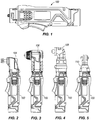
FIG. 1 is a side view of a tool handle according to one construction of the invention. -
FIG. 2 is a side view of an oscillating tool head attached to the handle ofFIG. 1 . -
FIG. 3 is a side view of a drill attachment head attached to the handle ofFIG. 1 . -
FIG. 4 is a side view of an impact driver attachment head attached to the handle ofFIG. 1 . -
FIG. 5 is a side view of a ratchet wrench attachment head attached to the handle ofFIG. 1 . -
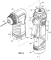
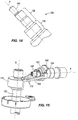
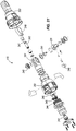
FIG. 6 is an exploded view of the drill attachment head and handle ofFIG. 3 . -
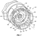
FIG. 7 is a detailed perspective view of a portion of an attachment head. -
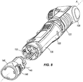
FIG. 8 is a perspective view of the drill attachment head and handle ofFIG. 3 showing a battery exploded from the handle. -
FIG. 9 is an exploded view of the handle ofFIG. 1 . -
FIG. 10 is a side view of the oscillating tool head ofFIG. 2 . -
FIG. 11 is an exploded view of the oscillating tool head ofFIG. 10 . -
FIG. 12A is a side view of a hex key for use with the oscillating tool head ofFIG. 10 . -
FIG. 12B is a bottom view of a flush cutting blade for use with the oscillating tool head ofFIG. 10 . -
FIG. 12C is a bottom view of a wood/metal blade for use with the oscillating tool head ofFIG. 10 . -
FIG. 12D is a bottom view of a sanding backing pad for use with the oscillating tool head ofFIG. 10 . -
FIG. 12E is a bottom view of sandpaper for use with the sanding backing pad ofFIG. 12D . -
FIG. 13 is a cross section of the oscillating tool head ofFIG. 10 taken in the same plane asFIG. 10 . -
FIG. 14 is a side view of an eccentric member of the oscillating tool head ofFIG. 13 . -
FIG. 15 is a perspective view of an oscillating drive of the oscillating tool head ofFIG. 13 . -
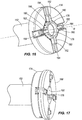
FIG. 16 is a perspective view of an arbor of the oscillating tool head ofFIG. 10 . -
FIG. 17 is a perspective view of an adapter attached to the arbor ofFIG. 16 . -
FIG. 18 is a side view of the adapter ofFIG. 17 . -
FIG. 19A is a front view of the adapter ofFIG. 18 . -
FIG. 19B is a rear view of the adapter ofFIG. 18 . -
FIG. 20 is a partial perspective view of the oscillating tool head ofFIG. 10 having a blade attached thereto. -
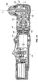
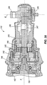
FIG. 21 is a cross section of the drill attachment head and handle ofFIG. 3 taken in the plane ofFIG. 3 . -
FIG. 22 is an exploded view of the drill attachment head ofFIG. 3 . -
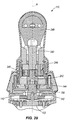
FIG. 23 is a perspective view of the impact driver attachment head ofFIG. 4 having a bit. -
FIG. 24 is an exploded view of the impact driver attachment head ofFIG. 23 . -
FIG. 25 is a cross section of the impact driver attachment head taken along line 25-25 inFIG. 23 . -
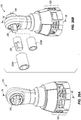
FIG. 26A is a rear perspective view of the ratchet wrench attachment head ofFIG. 5 . -
FIG. 26B is a front perspective view of the ratchet wrench attachment head ofFIG. 5 including an adapter and sockets. -
FIG. 27 is an exploded view of the ratchet wrench attachment head ofFIG. 26A . -
FIG. 28 is a cross section of the ratchet wrench attachment head taken along line 28-28 ofFIG. 26B . -
FIG. 29 is a cross section of the ratchet wrench attachment head taken along line 29-29 ofFIG. 26A . -
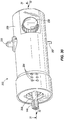
FIG. 30 is a perspective view of a rotary air vane motor for use with the tool handle ofFIG. 1 . -
FIG. 31 is a top view of the rotary air vane motor ofFIG. 30 with the housing and casing being transparent. -
FIG. 32 is a side view of the rotary air vane motor ofFIG. 30 with the housing cut out and casing being transparent. -
FIG. 33 is a perspective view of the rotary air vane motor ofFIG. 30 shown without the housing and casing. - Before any embodiments of the invention are explained in detail, it is to be understood that the invention is not limited in its application to the details of construction and the arrangement of components set forth in the following description or illustrated in the following drawings.
-
FIGS. 1-5 illustrate a mufti-function tool system according to one construction of the invention. The multi-function tool system includes a handle 100 (FIG. 1 ) and various attachment heads, for example 104, 106, 108, 110 (FIGS, 2 - 5 ), that attach to acommon handle 100 and are driven by a motor 102 (FIG. 9 ) housed within thehandle 100. In the illustrated construction, themotor 102 is 12V-DC, 2.0 Amps no load current. In other constructions, other suitable motors may be employed. In yet other constructions, a variable speed or multi-speed motor may be employed. -
FIG. 2 illustrates anoscillating attachment head 104 coupled with thehandle 100 and driven by themotor 102.FIG. 3 illustrates a right angledrill attachment head 106 coupled with thehandle 100 and driven by themotor 102.FIG. 4 illustrates a right angle impactdriver attachment head 108 coupled with thehandle 100 and driven by themotor 102.FIG. 5 illustrates a right angle ratchetwrench attachment head 110 coupled with thehandle 100 and driven by themotor 102. In other constructions, other motor-driven attachment heads may be attached to thehandle 100, and the attachments need not be right angle attachments. - The multi-function tool system utilizes a single
universal handle 100 for the various attachment heads 104-110.FIG. 6 illustrates thedrill attachment head 106 and thehandle 100 aligned along a longitudinal axis A for attachment between thedrill attachment head 106 and thehandle 100. The longitudinal axis A is defined by thehandle 100 having agrip portion 112 and by the head 104-110, as will be described in greater detail below. Thearrow 126 indicates the direction for attachment of theattachment head 106 to thehandle 100, which is parallel to the longitudinal axis A. The other attachment heads 104, 108, 110 are similarly attached to thehandle 100, and will be described in greater detail below. Referring toFIG. 7 , each of the attachment heads 104-110 includes a housing having a commonattachment head interface 122 for mating with ahandle interface 124 of ahousing 138 of thehandle 100. Theattachment head interface 122 includespins 128, or actuators, extending parallel to the axis A and surrounded bysemi-circular cavities 130 for receiving aboss 136 on thehandle interface 124, which will be described in greater detail below. Four equally spacedpins 128 andcavities 130 are spaced radially about the axis A on aninner surface 127 of theattachment head interface 122, theinner surface 127 defining amain cavity 125 for receiving thehandle interface 124. Thepins 128 are positioned at a first radial distance from the axis A. In other constructions fewer or more pins and cavities may be employed. Theattachment head interface 122 also includesaxial grooves 140 for receivingridges 141 on thehandle interface 124, as will be described in greater detail below. Four equally spacedgrooves 140 lie parallel to the axis A and are disposed on theinner surface 127 of theattachment head interface 122. In other constructions, fewer or more grooves may be employed. - The
attachment head interface 122 also includes rectangular openings orrecesses 132 positioned circumferentially about the attachment head 104-110 extending between theinner surface 127 and anouter surface 129 of theinterface 122 for receivingradial projections 142 on thehandle interface 124, which will be described in greater detail below. In the illustrated construction, fouropenings 132 are equally spaced from each other about the axis A; however, in other constructions, fewer or more openings may be employed and the openings may include other shapes. Theattachment head interface 122 also includes a star-shaped central opening orcentral recess 134 centered about the axis A for receiving a motordrive shaft projection 144 of thehandle interface 124, which will be described in greater detail below. In the illustrated construction, thecentral opening 134 is a six-point star shape with rounded tips; however, in other constructions, other numbers of points and other shapes may be employed. -
FIG. 6 illustrates thehandle interface 124. As the features of thehead interface 122 are formed on theinterior surface 127 of thehead interface 122, the features of thehandle interface 124 are formed on anexterior surface 131 of thehandle interface 124. Thus, theexterior surface 131 of thehandle interface 124 mates with theinterior surface 127 of thehead interface 122. Thehandle interface 124 includes a circular ring-shaped orU-shaped boss 136 extending from theouter surface 131 of thehandle interface 124 parallel to the axis A for mating with one of the fourpins 128 andsemi-circular cavities 130 on theattachment head interface 122. In other constructions, more than oneboss 136 may be employed. - The
boss 136 includes a central opening in which abutton 137, or linkage, is disposed, the central opening andbutton 137 extending in a direction substantially parallel to the longitudinal axis A. Thebutton 137 is positioned at a second radial distance from the longitudinal axis A, which is substantially equal to the first radial distance of thepins 128. Thebutton 137 is a safety device that prevents themotor 102 from being activated when there is no attachment head 104-110 attached to thehandle 100. Thebutton 137 is biased by a biasing member 139 (FIG. 9 ), such as a spring, to a locked position in which thebutton 137 is extended in theboss 136. In the locked position, a trigger stop 111 (FIG. 9 ) coupled to thebutton 137 prevents atrigger switch 113 from being moved to an actuated position, thus preventing themotor 102 from being activated. Thebutton 137 is depressed and moved substantially parallel to the longitudinal axis A to an unlocked position when one of thepins 128 of thehead interface 122 is received in the central opening of theboss 136. In the unlocked position, thebutton 137 is recessed in theboss 136. Thepin 128 engages thebutton 137 to depress thebutton 137, which positions the switch trigger stop 111 to allow thetrigger switch 113 to be actuated such that themotor 102 can be activated. Thebutton 137 prevents themotor 102 from being operable when no attachment head 104-110 is attached to thehandle 100. In other words, an attachment head must be attached to thehandle 100 in order for themotor 102 to be operable. - The
handle interface 124 also includes ridges 141 (FIG. 6 ) extending substantially parallel to axis A and projecting radially from theouter surface 131 of thehandle interface 124. Fourridges 141 are employed in the illustrated construction and mate with thegrooves 140 in theattachment head interface 122. In other constructions, fewer or more ridges and grooves may be employed. Thehandle interface 124 also includes rectangularradial projections 142 extending from thehousing 138 radially away from the axis A. Theprojections 142 mate with theopenings 132 in theattachment head interface 122. In the illustrated construction, twoprojections 142 are employed; however, in other constructions, fewer or more projections may be employed and the projections may have a shape other than rectangular. In the illustrated construction, there are fouropenings 132 and twoprojections 142. Preferably, the number ofopenings 132 is at least equal to the number ofprojections 142, although there may bemore openings 132 to allow the head 104-110 to be attached to thehandle 100 in various orientations, and the shape of the projections mate with the shape of the openings. - The
handle interface 124 also includes a motordrive shaft projection 144 centered about the axis A and extending from a motor drive shaft 150 (FIG. 9 ). The motordrive shaft projection 144 is star-shaped and mates with thecentral opening 134 in thehead interface 122. Therefore, both themotor drive shaft 150, motordrive shaft projection 144 andcentral opening 134 cooperate to define the longitudinal axis A, which is parallel and collinear when the head 104-110 is attached to thehandle 100. A second motor drive shaft projection 145 (FIG. 9 ) may be employed to further extend thedrive shaft 150 for connecting to some attachment heads. In the illustrated construction, a six-point star shape is employed. In other constructions, the motordrive shaft projection central opening 134 may have other shapes suitable for transferring rotational motion from the motordrive shaft projection 144 to the attachment head 104-110. - As illustrated in
FIG. 8 , thehandle 100 includes a removable andrechargeable battery pack 146. In the illustrated embodiment, thebattery pack 146 is a 12-volt battery pack and includes three (3) Lithium-ion battery cells. In other embodiments, the battery pack may include fewer or more battery cells such that the battery pack is a 14.4-volt battery pack, an 18-volt battery pack, or the like. Additionally or alternatively, the battery cells may have chemistries other than Lithium-ion such as, for example, Nickel Cadmium, Nickel Metal-Hydride, or the like. - The
battery pack 146 is inserted into a cavity 153 (FIG. 8 ) in thehandle housing 138 in the axial direction of axis A in order to snap into place. Thebattery pack 146 includes alatch 148, which can be depressed in the direction ofarrow 149 to release thebattery pack 146 from thehandle 100. In the illustrated construction, thebattery pack 146 has a capacity of 1.5 amp hours. In other constructions, other suitable batteries and battery packs may be employed. In yet other constructions, the tool handle 100 can include a cord and be powered by a remote source of power, such as a utility source connected to the cord. -
FIG. 9 is an exploded view of thehandle 100 according to one construction of the invention. Thehandle 100 includes themotor 102, themotor drive shaft 150 centered about the axis A, the motordrive shaft projection 144 coupled to themotor drive shaft 150, and ahandle housing assembly 114 including thehousing 138 and thehandle interface 124. Theradial projections 142 are formed separately from thehousing 138 and project frombutton members 115, respectively, to form depressible release buttons.Button members 115 andprojections 142 are disposed in thehandle interface 124 and compression springs 116 are disposed between thebutton members 115, which bias theprojections 142 outwardly from one another to a fully projected first position which is at a first radial distance from the longitudinal axis A. Theprojections 142 are depressible inwards towards the longitudinal axis A to a depressed second position which is at a second radial distance from the longitudinal axis A. The second radial distance is less than the first radial distance. - The
handle 100 also includes aswitch assembly 117, theswitch trigger 113 and theswitch trigger stop 111. Theswitch trigger 113 is coupled with thehousing 138 and is depressible to actuate theswitch assembly 117 when in a depressed position. Theswitch trigger 113 is biased to a non-depressed position by aspring 118. Theswitch assembly 117, when actuated, electrically couples thebattery 146 and themotor 102 to run themotor 102. Theswitch trigger stop 111 is coupled to thebutton 137 disposed in theboss 136 and provides a barrier to prevent theswitch trigger 113 from being movable to the actuated position (e.g., in which themotor 102 is supplied with power) when thebutton 137 is not depressed, as described above, When thebutton 137 is depressed, the switch trigger stop 111 moves to another position in which theswitch trigger 113 may be depressed to the actuated position. - The
handle 100 also includes a forward/reverse switch 119 (FIG. 6 ) having a first position, indicated by thearrow 101, for running themotor 102 in a first direction and a second position, indicated by thearrow 103, for running themotor 102 in a second direction opposite the first direction (e.g., forward and reverse). Other parts includescrews 121 withspring washers 123, amotor mount 133, ahousing connection knob 135, adata label 143,screws 147 for coupling thehousing 138 together and alogo label 151. -
FIG. 10 illustrates theoscillating attachment head 104 according to one construction of the invention. Theoscillating attachment head 104 converts rotary motion of themotor drive shaft 150 into oscillating motion of atool shaft 152.FIG. 11 is an exploded view of theoscillating attachment head 104, andFIGS. 12A-12E illustrate accessories for use with theoscillating attachment head 104. Thetool shaft 152 defines a longitudinal axis B perpendicular to the axis A.FIG. 13 illustrates a cross section of theoscillating attachment head 104 attached to thehandle 100. As shown inFIG. 13 , the motordrive shaft projection 144 is coupled to aneccentric shaft 154 housed in theoscillating attachment head 104. Thedrive shaft projection 144 is received in thecentral opening 134, which is formed in amember 156. Theeccentric shaft 154 is in turn coupled to themember 156 for rotation therewith. - The
eccentric shaft 154 is illustrated separately inFIGS. 14 and 15 , and includes aneccentric portion 158 that is not centered about the axis A. Acounter balance 160 is press fit on a centeredportion 159 of theeccentric shaft 154, and a ball bearingeccentric member 162 is press fit on theeccentric portion 158 of theeccentric shaft 154. Thecounter balance 160 counters the off-center rotation of theeccentric portion 158 and the ball bearingeccentric member 162 to reduce vibrations caused by the eccentric rotation thereof. Theeccentric shaft 154 also includes ashaft extension 164 centered about the axis A. As shown inFIGS. 13 and15 , abearing 166 is coupled to the outer circumference of theshaft extension 164. Thebearing 166 is held in ahousing 155 of theoscillating attachment head 104. Thebearing 166 andshaft extension 164, with the support of thehousing 155, constrain theeccentric shaft 154 to rotation about the axis A to reduce vibrations caused by rotation of theeccentric portion 158. - A forked
member 168 is coupled to theoscillating tool shaft 152 by asleeve 170 and includes twoprongs 172. Theprongs 172 are positioned adjacent opposite sides of the ball bearingeccentric member 162 and transfer eccentric rotary motion of the ball bearingeccentric member 162 into oscillating motion of theoscillating tool shaft 152 about the axis B. - As shown in
FIG. 16 , theoscillating tool shaft 152 terminates, at a free end, with anarbor 174. In the illustrated construction, thearbor 174 is unitarily formed with theoscillating tool shaft 152; however, in other constructions, thearbor 174 may be a separate piece coupled with theoscillating tool shaft 152. Thearbor 174 includes a central locating portion having a raisedlocating feature 176. The raisedlocating feature 176 has an octagon shape with a central,circular aperture 178 therethrough and fourarms 180 extending radially therefrom. In the illustrated construction, each of thearms 180 extends from a side of the locatingfeature 176. Each of thearms 180 is angularly spaced about 90 degrees apart from theadjacent arms 180 and includes a generally pointedtip 182 having a small round. Thearbor 174 also includes fourgrooves 184 extending radially from the octagonal raised locatingfeature 176, andshallower grooves 186 connecting the fourradial grooves 184 around a periphery of the raised locatingfeature 176. Each of the fourarms 180 is raised out of one of the fourradial grooves 184 and extends parallel thereto. - As shown in
FIGS. 17-20 , theoscillating attachment head 104 also includes a two-sided adapter 188 for mating with thearbor 174 and modifying the raised locatingfeature 176 in two configurations. Theadapter 188 includes anopening 190 shaped to receive the raised locatingfeature 176 of thearbor 174. Specifically, theopening 190 is shaped as an octagon having four arms extending radially therefrom. Each of the arms is angularly spaced about 90 degrees apart from the adjacent arms and includes a generally pointed tip with a small round. A first side 192 (FIG. 19A ) of theadapter 188 provides a first modified raised locating feature including a first set of four raised elliptical or oval-shapedprojections 196 angularly spaced approximately 90 degrees apart, each of theprojections 196 located proximate one of the arms of theopening 190 at a first radial distance. The first set of raisedprojections 196 is raised from fourchannels 198 extending radially from each of the four arms of theopening 190 on thefirst side 192. A second side 200 (FIG. 19B ) of theadapter 188 provides a second modified raised locating feature including a second set of four raised elliptical or oval-shapedprojections 202 angularly spaced approximately 90 degrees apart, each of theprojections 202 located proximate one of the arms of theopening 190 at a second radial distance different from the first radial distance, the second distance being greater than the first distance in the illustrated construction. The second set of raisedprojections 202 is raised from fourchannels 206 extending radially from each of the four arms of theopening 190 on the second side. - In one use of the
arbor 174, a tool or blade having a twelve-point star opening is provided for mating with thearbor 174, although other tools may also be utilized. Examples oftools arbor 174 are shown inFIG. 12B-12D . A twelve-point star tool is illustrated in expiredU.S. Patent No. 4,989,320 and includes an opening having substantially linear star-shaped edges. A sandingpad toot attachment 163 also has the twelve-point star opening and may be used with various types of sandpaper 165 (FIG. 12E ), such as 60 grit, 80 grit and 120 grit sandpaper, amongst others. Theadapter 188 is used to mate with other tools or blades having differently-shaped openings. Referring toFIG. 20 , ablade 177 is secured between asleeve 167 and thearbor 174, or between thesleeve 167 and theadapter 188, if theadapter 188 is necessary. In the illustrated construction, theadapter 188 is used to secure theblade 177. Ascrew 169 and O-ring 171 (FIG. 11 ) fasten thesleeve 167,blade 177, and, if necessary, theadapter 188, to thearbor 174 through theopenings FIG. 12A ) is used to engage thescrew 169 to tighten and loosen thescrew 169. - As illustrated in
FIG. 11 , theoscillating attachment head 104 also includes arear head housing 175, orhead interface 122, coupled to thehousing 155 and having an O-ring 181 therebetween. Arubber boot 183 covers thehousing 155 andrear head housing 175 in the final assembly of theoscillating attachment head 104. Therubber boot 183 covers an outer surface of thehead interface 122. Thehead 104 also includesscrews 185, arubber bearing seat 187,washers 189 and screws 191. -
FIGS. 3 and21-22 illustrate thedrill head attachment 106 according to one construction of the invention. Thedrill attachment head 106 is a compact, right angled tool for manipulation in small spaces.FIG. 21 shows a cross-section of thedrill head attachment 106 coupled to thehandle 100.FIG. 22 illustrates an exploded view of thedrill head attachment 106. Thedrill head attachment 106 includes asun gear 194 coupled with the motordrive shaft projection 144 for rotation therewith. Abevel pinion 195 is centered about the axis A and receives rotational motion from thesun gear 194 by way ofplanetary gears carrier 201,ring gear 203 andsun gear 204, amongst other associated parts, in a manner well understood in the art. Thebevel pinion 195 mates with abevel gear 207 to transfer rotational movement of thebevel pinion 195 to rotational movement of anoutput shaft 208. Theoutput shaft 208 defines a longitudinal output axis C perpendicular to the axis A and is coupled to achuck assembly 209 for receiving and grasping a bit 210 (FIG. 6 ). The total gear ratio of the illustrateddrill head attachment 106 is about 36.38. In other constructions, thedrill head attachment 106 may have other desired gear ratios. - As illustrated in
FIG. 22 , thedrill head attachment 106 is housed within ahousing cover assembly 211, which is coupled to agear housing 213 having arubber boot 215 therearound. Thegear housing 213 andrubber boot 215 form thehead interface 122 for the drillhead attachment head 106. Thechuck assembly 209 is coupled to thehousing cover assembly 211. The drillhead attachment head 106 also includes various washers, fasteners, rings, bearings and the like, which are shown inFIG. 22 . -
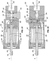
FIGS. 23-25 illustrate the impactdriver attachment head 108 according to one construction of the invention. Theimpact driver head 108 is a compact, right angled tool for manipulation in small spaces. The impactdriver attachment head 108 includes acoupler 212 that receives abit 214. An exploded view of the impactdriver attachment head 108 is shown inFIG. 24 . -
FIG. 25 is a cross section of the impactdriver attachment head 108. The impactdriver attachment head 108 includes amotor pinion 216 that includes thecentral opening 134 for receiving the motordrive shaft projection motor 102 to ahammer 217 with the cooperation of acam shaft 218, aring gear 219 and planetary gears 221 (FIG. 24 ). Thehammer 217 rotates freely and then impacts ananvil 223 to provide a high torque impact, which is transferred to anoutput shaft 224 by way of aspiral bevel pinion 225 andspiral bevel gear 226. Theoutput shaft 224 is coupled to asleeve 228 by way of aretainer ring 229, anupper spring washer 230, aspring sleeve 231,balls 232 and a C-ring 233. Together, theoutput shaft 224 andsleeve 228 form thecoupler 212. Theoutput shaft 224 defines a longitudinal output axis D oriented perpendicular to the axis A. The total gear ratio of the impactdriver attachment head 108 is about 9.33. In other constructions, the impactdriver attachment head 108 may have other desirable gear ratios. - As shown in
FIG. 24 , the impactdriver attachment head 108 is housed within agear case 234 and arear gear housing 235. The gear case is covered by arubber boot 236 and is coupled to therear gear housing 235, which is covered with arear rubber boot 237. Therear gear housing 235 forms thehead interface 122 for the impactdriver attachment head 108. The impactdriver attachment head 108 also includes various washers, fasteners, rings, bearings and the like, which are shown inFIG. 24 . -
FIGS. 26A and 26B illustrate theratchet attachment head 110 according to one construction of the invention. Theratchet attachment head 110 is a compact, right angle tool for manipulation in small spaces. Theratchet attachment head 110 includes a drive shank, or 3/8inch hex head 239, and adial 240, or forward/reverse knob cover, coupled with a direction knob 241 (FIG. 27 ). In other constructions, thehex head 239 may be a size smaller or larger than 3/8 inch. As shown inFIG. 26B , thehex head 239 receives asocket adaptor 220 andsockets FIG. 27 is an exploded view of theratchet attachment head 110.FIGS. 28 and29 are cross sections of theratchet attachment head 110. - The
ratchet attachment head 108 includes apinion 242 that includes thecentral opening 134 for receiving the motordrive shaft projection motor 102 to aneccentric shaft 243 by way of aring gear assembly 244,planetary gears 245 andcarrier 246. Theeccentric shaft 243 includes aprojection 247 that rotates off-center to cause oscillating motion of anadjacent yoke head 248 about an axis E. Oscillating rotational motion of theyoke head 248 is transferred to a single-direction rotational motion of ahex head 239 having aratchet 249. Theratchet 249 allows for transferring only one direction of the oscillating motion of theyoke head 248 to thehex head 239 such that thehex head 239 rotates in a single direction in operation. Thedial 240 anddirection knob 241 are rotatable between two positions: a first position allowing rotation of thehex head 239 in a first direction (e.g., forward) and a second position allowing rotation of thehex head 239 in a second direction opposite the first direction (e.g., reverse). Thehex head 239 defines the longitudinal axis E, which is perpendicular to the axis A. - The
ratchet attachment head 110 is housed within agear housing 250 and ahandle 251. Arubber boot 252 is disposed on an outer surface of thegear housing 250 and thehandle 251. - In another construction, the
handle 100 may be a pneumatic tool handle 100 powered by pressurized air flow through a rotaryair vane motor 253, illustrated inFIGS. 30-33 . In this construction, instead of thebattery 146 andelectric motor 102, thehandle 100 includes the rotaryair vane motor 253 and a connector (not shown) for receiving pressurized air. The remaining components of thehandle 100 remain substantially the same as described above, it being understood that dimensions and geometry are adjustable to accommodate the rotaryair vane motor 253, and the similar components will not be described in further detail. However, thehandle interface 124 remains the same so as to be connectable to thetool head interface 122 in the same manner as described above. The motordrive shaft projection 144, described above, is coupled to adrive shaft 258 of the rotaryair vane motor 253 for mating with the transmission of the attachment heads 104-110, as described above. - In the illustrated construction, the
air vane motor 253 is a five vane reversible motor. In other constructions, theair vane motor 253 may include a different number of vanes and need not be reversible. Furthermore, other suitable types of pneumatic motors may be employed. - With reference to
FIGS. 30-33 , theair vane motor 253 includes a forward/reverse selector 255, aspeed selector 256, anactuator 257, adrive shaft 258, arotor 265 mounted to thedrive shaft 258,vanes 266, and ahousing 259. Pressurized air enters themotor 253 and expands against thevanes 266 of theair vane motor 253, thus providing a force that causes therotor 265 and driveshaft 258 to rotate. Thedrive shaft 258 rotates about the axis A, as described above with respect to theelectric motor 102. Themotor 253 includes acasing 267 surrounding therotor 265, thecasing 267 includingexhaust ports 268 positioned to direct flow away from thevanes 266 in a radial direction. The flow ofair 254 enters themotor 253 at the connector (not shown) and exits themotor 253 throughside exhaust openings 264 in thehousing 259, which are positioned in a direction substantially perpendicular to the axis A. Thehousing 259 includespassageways 263 between the connector (not shown) and theexhaust openings 264 for directing the flow ofair 254 through themotor 253. - The
speed selector 256 extends from thehousing 249 and is coupled to aspeed valve assembly 261 for adjusting the flow ofair 254 through theair vane motor 253 such that the speed of thedrive shaft 258 is adjustable. Thespeed selector 256 is rotatable and, in turn, rotates thespeed valve assembly 261. Thespeed valve assembly 261 includes anopening 262 that is rotatable between a first position, in which theopening 262 is substantially aligned with thepassageways 263 directing the flow ofair 254 through thehousing 259, and a second position, or range of positions, in which theopening 262 is partially aligned with thepassageways 263, thus restricting thepassageways 263. The second position includes a range of positions in which thespeed valve assembly 261 variably restricts the flow ofair 254 through thehousing 259 to adjust the speed of air through thehousing 259, thus adjusting the force on thevanes 266 and the output speed of thedrive shaft 258. - The forward/
reverse selector 255 extends from thehousing 259 and is coupled to adirection valve assembly 260 for switching themotor 253 between forward and reverse directions of rotation, as is well understood in the art. The forward/reverse selector 255, and in turn, thedirection valve assembly 260, are rotatable between a first position in which thedirection valve assembly 260 directs the air such that thedrive shaft 258 rotates in a forward direction and a second position in which thedirection valve assembly 260 directs the air such that thedrive shaft 258 rotates in a reverse direction opposite the forward direction. - The
actuator 257 extends from thehousing 259 and is movable in an axial direction between a first position in which flow ofair 254 to thevanes 266 is allowed and a second position in which flow ofair 254 to thevanes 266 is inhibited. Theswitch trigger 113, described above, is configured to move theactuator 257 to the first position when a user presses theswitch trigger 113. Theactuator 257 is biased to the second position such that theair vane motor 253 is not actuated. - The
housing assembly 114, described above, is adapted to accommodate the rotaryair vane motor 253. As described above, thehousing assembly 114 includes thehousing 138 and thehandle interface 124 for mating with thehead interface 122. - In operation, various attachment heads 104-110 are coupled with the
handle 100 for being driven by themotor head interface 122 is radially symmetrical and can be divided into four equal parts such that the attachment heads 104-110 may be coupled to thehandle 100 in four different rotational orientations positioned about the axis A. As the attachment head 104-110 is coupled with thehandle 100, theradial projections 142 are pushed radially inward toward the axis A, against the bias ofsprings 116, until theopenings 132 align with therelease buttons 115. Theopenings 132 receive therelease buttons 115 therein by way of the biasing force of thesprings 116 to hold the attachment head 104-110 in place relative to thehandle 100. At the same time, one of the fourpins 128 and the corresponding one of the fourcavities 130 mate with theboss 136, theridges 141 mate with thegrooves 140 to align the head 104-110 with thehandle 100 in one of the four orientations. The inclusion of fourpins 128 and fourcavities 130 on thehead interface 122 allows the attachment head 104-110 to actuate thebutton 137, and thereby the lock-off feature, in any of the four orientations. Further, the motordrive shaft projection 144 mates with thecentral opening 134 to drivingly connect themotor 102 to the attachment head 104-110. - To operate the tool, the operator actuates the
switch trigger 113 on the handle, which activates themotor 102 to drive the attachment head 104-110 as long as the attachment head 104-110 is attached to thehandle 100 and thebutton 137 is depressed. When the attachment head 104-110 is not attached to thehandle 100, theswitch trigger 113 is immobilized by thetrigger stop 111 and themotor 102 will not operate. To release the attachment head 104-110, an operator depresses therelease buttons 115 toward the axis A and pulls the attachment head 104-110 away from thehandle 100 in a direction parallel to the axis A. - A power tool, comprising: a tool handle including a grip portion defining a longitudinal axis, a motor disposed within the handle and including a drive shaft having an axis of rotation substantially parallel to the longitudinal axis of the grip portion, a trigger positioned adjacent the grip portion for selectively activating the motor, and a handle interface; and a tool head for selectively coupling to the tool handle, the tool head including a head interface for coupling with the handle interface of the tool handle, a transmission driven by the drive shaft of the motor when the tool head is coupled to the tool handle, and an output member coupled to the transmission, the output member defining an axis generally perpendicular to the axis of rotation of the drive shaft. The power tool handle may further comprises a button disposed on the handle and movable in a direction defining an axis substantially parallel to the longitudinal axis, the button movable to a first position by the tool head when the tool head is coupled to the handle wherein in the first position the trigger can actuate the motor, and the button movable to a second position when the tool head is removed from the handle wherein the trigger is inhibited from actuating the motor. The power tool head may further comprises a pin extending substantially parallel to the longitudinal axis of the grip portion when the tool head is attached to the tool handle, the pin contacting the button in order to move the button to the first position. The power tool handle may further include a projection extending radially outward from the longitudinal axis and wherein the tool head further includes an opening for receiving the projection, wherein the projection is biased radially outwardly for being received by the opening when the tool head is coupled to the tool handle, and wherein the projection is depressible for selectively releasing the tool head from the tool handle.
- A power tool, comprising: a handle; a head selectively coupled to the handle; a motor having a drive shaft extending therefrom, the drive shaft having a first central axis; an opening for receiving the drive shaft of the motor for transferring rotation of the drive shaft to a tool output, the opening defining a second central axis; a trigger for activating the motor; a trigger stop movable between a first position and a second position, wherein in the first position the trigger stop engages the trigger in order to lock the trigger and prevent activation of the motor, and in the second position the trigger is unlocked to permit activation of the motor; a linkage coupled to the trigger stop, wherein the linkage is positioned at a first radial distance from the first central axis; and a plurality of actuators extending from the head and positioned at a second radial distance from the second central axis, the first radial distance being substantially equal to the second radial distance, wherein when the head is coupled to the handle in a first rotational orientation, one of the plurality of actuators engages the linkage to move the trigger stop to the second position, and when the head is coupled to the handle in a second rotational orientation different from the first rotational orientation, another one of the plurality of actuators engages the linkage to move the trigger stop to the second position. The plurality of actuators may extend substantially parallel to the second central axis, and wherein the linkage is movable in a direction substantially parallel to the first central axis between a first position in which the trigger is locked and a second position in which the trigger is unlocked. The plurality of actuators may include four actuators spaced about the second central axis approximately 90 degrees apart such that the head is coupleable to the handle in four rotational orientations. The power tool handle further may include a projection extending radially outward from the first central axis and wherein the tool head further includes an opening for receiving the projection, wherein the projection is biased radially outwardly for being received by the opening when the tool head is coupled to the tool handle, and wherein the projection is depressible for selectively releasing the tool head from the tool handle. The power tool may further comprises: ridges associated with one of the handle and the head, the ridges extending substantially parallel to one of the first and second central axes; and grooves associated with the other of the handle and the head, the grooves extending substantially parallel to the other of the first and second central axes for receiving the ridges and locating the head in one of the first and second rotational orientations.
Claims (10)
- A power tool handle selectively connectable to a power tool head, the power tool handle comprising:a handle (100) including a grip portion (112), the grip portion (112) defining a longitudinal axis;a motor (102) housed within the handle (100) and including a drive shaft (150) driven by the motor (102), the drive shaft (150) mounted for rotation within the handle (100) and defining an axis of rotation substantially parallel to the longitudinal axis of the handle (100);a trigger (113) disposed proximate the grip portion (112) of the handle (100) for actuating the motor (102); anda button (137) disposed on the power tool handle (100) and movable in a direction defining an axis substantially parallel to the longitudinal axis, the button (137) movable to a first position by the tool head when the tool head is coupled to the handle (100) wherein in the first position the trigger (113) can actuate the motor (102), and the button (137) movable to a second position when the tool head is removed from the handle (100) wherein the trigger (113) is inhibited from actuating the motor (102),
- The power tool handle of claim 1, and further comprising a boss extending from the handle and an opening positioned within the boss and oriented in a direction substantially parallel to the longitudinal axis, wherein the button is disposed in the opening.
- The power tool handle of claim 1 wherein the button is biased to the second position.
- The power tool handle of claim 1, and further comprising an extension coupled to the button and including a stop member, wherein when the button is in the second position the stop member abuts the trigger to prevent actuation of the motor.
- The power tool handle of claim 1, and further comprising ridges projecting from an outer surface of the handle and extending substantially parallel to the longitudinal axis, the ridges for mating with the tool head.
- The power tool handle of claim 1, and further comprising:a first projection extending from the outer surface of the handle radially away from the longitudinal axis in a first direction; anda second projection extending from the outer surface of the handle radially away from the longitudinal axis in a second direction generally opposite the first direction,wherein the first and second projections are moveable between first and second positions,wherein in the first position, the projections are at a first radial distance from the longitudinal axis and are received within a portion of the tool head to couple the tool head to the handle,wherein in the second position, the projections are at a second radial distance from the longitudinal axis that is less than the first radial distance and the projections are decoupled from the tool head, andfurther wherein the first and second projections are biased to the first position.
- A power tool head (106) removably connectable to a power tool handle (100), the power tool handle (100) including an interface (124) for being received by the power tool head (106), a motor (102), a drive shaft (150) driven by the motor (102), a release member and a trigger lock button (137) disposed in a raised boss, the power tool head (106) comprising:an output for performing an operation on a work piece;a housing having an inner surface defining a main cavity for receiving the handle (100) of the power tool, the housing (100) having an outer surface generally opposite the inner surface;a first opening (125) adjacent the cavity for selectively receiving the drive shaft for transferring rotation of the drive shaft to a tool output, the opening defining a central axis;a pin (128) extending substantially parallel to the central axis for depressing the button (137); anda second opening (132) extending from the inner surface to the outer surface in a direction generally radial with respect to the central axis for receiving radial projections (142) of the handle (100).
- The power tool head of claim 7, wherein the pin is a plurality of pins extending substantially parallel to the central axis, wherein the plurality of pins are evenly spaced circumferentially about the central axis.
- The power tool head of claim 7, wherein the pin is surrounded by a semi-circular cavity adjacent the main cavity,
- The power tool head of claim 7, further comprising grooves recessed in the inner surface and extending in a direction substantially parallel to the central axis for receiving ridges of the handle for alignment between the handle and the tool head.
Priority Applications (2)
| Application Number | Priority Date | Filing Date | Title |
|---|---|---|---|
| EP13184431.8A EP2674259B1 (en) | 2009-12-18 | 2010-12-14 | Multi-function tool system |
| EP11006526.5A EP2388107B1 (en) | 2009-12-18 | 2010-12-14 | Multi-function tool system |
Applications Claiming Priority (1)
| Application Number | Priority Date | Filing Date | Title |
|---|---|---|---|
| US28794009P | 2009-12-18 | 2009-12-18 |
Related Child Applications (5)
| Application Number | Title | Priority Date | Filing Date |
|---|---|---|---|
| EP11006526.5A Division EP2388107B1 (en) | 2009-12-18 | 2010-12-14 | Multi-function tool system |
| EP11006526.5A Division-Into EP2388107B1 (en) | 2009-12-18 | 2010-12-14 | Multi-function tool system |
| EP13184431.8A Division EP2674259B1 (en) | 2009-12-18 | 2010-12-14 | Multi-function tool system |
| EP13184431.8A Division-Into EP2674259B1 (en) | 2009-12-18 | 2010-12-14 | Multi-function tool system |
| EP11006526.5 Division-Into | 2011-08-09 |
Publications (3)
| Publication Number | Publication Date |
|---|---|
| EP2338644A2 EP2338644A2 (en) | 2011-06-29 |
| EP2338644A3 EP2338644A3 (en) | 2013-02-27 |
| EP2338644B1 true EP2338644B1 (en) | 2019-06-26 |
Family
ID=43982386
Family Applications (3)
| Application Number | Title | Priority Date | Filing Date |
|---|---|---|---|
| EP10252114.3A Not-in-force EP2338644B1 (en) | 2009-12-18 | 2010-12-14 | Multi-function tool system |
| EP13184431.8A Not-in-force EP2674259B1 (en) | 2009-12-18 | 2010-12-14 | Multi-function tool system |
| EP11006526.5A Not-in-force EP2388107B1 (en) | 2009-12-18 | 2010-12-14 | Multi-function tool system |
Family Applications After (2)
| Application Number | Title | Priority Date | Filing Date |
|---|---|---|---|
| EP13184431.8A Not-in-force EP2674259B1 (en) | 2009-12-18 | 2010-12-14 | Multi-function tool system |
| EP11006526.5A Not-in-force EP2388107B1 (en) | 2009-12-18 | 2010-12-14 | Multi-function tool system |
Country Status (3)
| Country | Link |
|---|---|
| US (4) | US8695725B2 (en) |
| EP (3) | EP2338644B1 (en) |
| CN (4) | CN102303307B (en) |
Families Citing this family (84)
| Publication number | Priority date | Publication date | Assignee | Title |
|---|---|---|---|---|
| US8172642B2 (en) | 2008-08-20 | 2012-05-08 | Black & Decker Inc. | Multi-sander |
| EP2338644B1 (en) | 2009-12-18 | 2019-06-26 | Techtronic Power Tools Technology Limited | Multi-function tool system |
| DE102010030433A1 (en) * | 2010-06-23 | 2011-12-29 | Robert Bosch Gmbh | Hand tool with a striking mechanism |
| US9149923B2 (en) | 2010-11-09 | 2015-10-06 | Black & Decker Inc. | Oscillating tools and accessories |
| US9120213B2 (en) | 2011-01-21 | 2015-09-01 | Milwaukee Electric Tool Corporation | Powered ratchet wrench |
| EP2489312A1 (en) * | 2011-02-15 | 2012-08-22 | Zimmer Surgical SA | Compact driver for powered surgical tool |
| WO2012142188A2 (en) * | 2011-04-11 | 2012-10-18 | Milwaukee Electric Tool Corporation | Hydraulic hand-held knockout punch driver |
| CN102259329B (en) * | 2011-06-22 | 2013-08-21 | 南京德朔实业有限公司 | Multifunctional electric power tool |
| DE102011078380A1 (en) * | 2011-06-30 | 2013-01-03 | Robert Bosch Gmbh | Drywall screw driver for system, has housing with screw depth limiting element, gear unit and battery receiving area that is arranged radially within housing |
| US20130008677A1 (en) * | 2011-07-08 | 2013-01-10 | Chen Huifu | Multi-head power tool |
| US9421682B2 (en) | 2011-07-18 | 2016-08-23 | Black & Decker Inc. | Multi-head power tool with reverse lock-out capability |
| US9776315B2 (en) | 2011-11-11 | 2017-10-03 | Black & Decker Inc. | Power tool having interchangeable tool heads with an independent accessory switch |
| US9314852B2 (en) | 2011-12-15 | 2016-04-19 | Black & Decker Inc. | Right angle attachment for power tools |
| EP2799188A4 (en) * | 2011-12-28 | 2015-08-12 | Positec Power Tools Suzhou Co | Power tool |
| TWM433930U (en) * | 2012-01-17 | 2012-07-21 | Basso Ind Corp | Packing device for right angle head impact wrench |
| TWM433266U (en) * | 2012-03-12 | 2012-07-11 | jun-yu Lin | Structure improvement on pneumatic wrench |
| DE102012206884A1 (en) * | 2012-04-26 | 2013-10-31 | Robert Bosch Gmbh | Hand tool |
| US8878490B2 (en) * | 2012-05-07 | 2014-11-04 | Milwaukee Electric Tool Corporation | Twist on battery pack |
| DE202013103023U1 (en) * | 2012-07-14 | 2013-10-04 | Hitachi Koki Co., Ltd. | power tool |
| WO2014022534A1 (en) | 2012-07-31 | 2014-02-06 | Milwaukee Electric Tool Corporation | Multi-operational valve |
| US9186788B2 (en) | 2012-11-15 | 2015-11-17 | Techtronic Power Tools Technology Limited | Lockout mechanism |
| DE102012221748A1 (en) * | 2012-11-28 | 2014-05-28 | Robert Bosch Gmbh | Hand tool |
| JP6050110B2 (en) | 2012-12-27 | 2016-12-21 | 株式会社マキタ | Impact tools |
| US9956676B2 (en) * | 2013-01-09 | 2018-05-01 | Techtronic Power Tools Technology Limited | Tool with rotatable head |
| US10926383B2 (en) * | 2013-03-14 | 2021-02-23 | Milwaukee Electric Tool Corporation | Impact tool |
| US9956677B2 (en) | 2013-05-08 | 2018-05-01 | Black & Decker Inc. | Power tool with interchangeable power heads |
| US20150059531A1 (en) * | 2013-08-29 | 2015-03-05 | Ingersoll-Rand Company | Ratchet Tools |
| TWM475341U (en) * | 2013-10-04 | 2014-04-01 | Tranmax Machinery Co Ltd | Switch component for use in power tool |
| GB2519962A (en) * | 2013-11-01 | 2015-05-13 | Robert Fowler | A handheld power tool |
| US9592591B2 (en) | 2013-12-06 | 2017-03-14 | Ingersoll-Rand Company | Impact tools with speed controllers |
| US10014128B2 (en) * | 2013-12-17 | 2018-07-03 | Robert Bosch Tool Corporation | Portable power tool with trigger switch, trigger release and lock-on mechanism combination |
| US10150210B2 (en) * | 2014-04-04 | 2018-12-11 | Robert Bosch Tool Corporation | Power hand tool with improved oscillating eccentric and fork mechanism |
| CN103963023A (en) * | 2014-04-24 | 2014-08-06 | 天佑电器(苏州)有限公司 | Combined electric tool and control method thereof |
| US9751176B2 (en) | 2014-05-30 | 2017-09-05 | Black & Decker Inc. | Power tool accessory attachment system |
| US9698650B2 (en) * | 2014-06-02 | 2017-07-04 | Regal Beloit America, Inc. | Electric device, gearbox and associated method |
| USD732364S1 (en) * | 2014-07-02 | 2015-06-23 | Mcginley Engineered Solutions, Llc | Removable chuck |
| US9991825B1 (en) | 2014-11-24 | 2018-06-05 | The Toro Company | Outdoor power equipment system with modular motor and modular battery |
| CN206343269U (en) * | 2014-12-17 | 2017-07-21 | 菲活机器制造公司 | Modular system for performing multiple broken and process of lapping |
| DE102016202831A1 (en) * | 2015-02-25 | 2016-08-25 | Robert Bosch Gmbh | Hand tool |
| US20180001588A1 (en) * | 2015-03-25 | 2018-01-04 | Disha KATHARANI | Automated multi-purpose quilling device |
| DE102015206634A1 (en) * | 2015-04-14 | 2016-10-20 | Robert Bosch Gmbh | Tool attachment for a hand tool |
| USD764248S1 (en) * | 2015-04-22 | 2016-08-23 | Nomis Llc | Right angle drive |
| FR3039087B1 (en) * | 2015-07-22 | 2018-03-09 | Innovation Fabrication Commercialisation Infaco | MULTIFUNCTIONAL ELECTROPORTATIVE TOOL |
| TW201706084A (en) * | 2015-08-13 | 2017-02-16 | 陳秀如 | Pneumatic tool motor having an internal hammering device |
| TWI548497B (en) * | 2015-08-25 | 2016-09-11 | Pneumatic tools with trigger | |
| USD789171S1 (en) * | 2016-01-21 | 2017-06-13 | Nomis Llc | Right angle drive |
| JP6758960B2 (en) * | 2016-07-05 | 2020-09-23 | 株式会社マキタ | Rechargeable power tool |
| DE102017211774A1 (en) * | 2016-07-11 | 2018-01-11 | Robert Bosch Gmbh | Hand machine tool device |
| DE102017211772A1 (en) * | 2016-07-11 | 2018-01-11 | Robert Bosch Gmbh | Hand machine tool device |
| DE102016214616A1 (en) * | 2016-08-05 | 2018-02-08 | Robert Bosch Gmbh | attachment device |
| US10632589B2 (en) | 2016-08-29 | 2020-04-28 | Black & Decker Inc. | Power tool |
| EP3338957A1 (en) * | 2016-12-23 | 2018-06-27 | HILTI Aktiengesellschaft | Tool device |
| EP3338958A1 (en) * | 2016-12-23 | 2018-06-27 | HILTI Aktiengesellschaft | Tool device |
| US20180178366A1 (en) * | 2016-12-23 | 2018-06-28 | Andrei Matei | Modular tool system |
| EP3338959A1 (en) * | 2016-12-23 | 2018-06-27 | HILTI Aktiengesellschaft | Tool device |
| CN206748357U (en) * | 2017-06-05 | 2017-12-15 | 钱贤峰 | A kind of electric tool for easily changing function |
| CA3064576A1 (en) * | 2017-06-09 | 2018-12-13 | Stryker Corporation | Surgical systems with twist-lock battery connection |
| DE102018209307A1 (en) * | 2017-06-22 | 2018-12-27 | Robert Bosch Gmbh | Tool base module |
| US20190015963A1 (en) * | 2017-07-13 | 2019-01-17 | Tti (Macao Commercial Offshore) Limited | Power tool including power tool base couplable with power tool implements |
| SI3446834T1 (en) * | 2017-08-24 | 2020-04-30 | Scheppach Fabrikation Von Holzbearbeitungsmaschinen Gmbh | Electric hammer |
| US20190126418A1 (en) * | 2017-10-02 | 2019-05-02 | Bachus and Son, Inc. | Battery Powered Right Angle Aircraft Drill |
| WO2019080859A1 (en) * | 2017-10-24 | 2019-05-02 | 苏州科瓴精密机械科技有限公司 | Handle assembly and gardening tool having same |
| EP3701782A4 (en) * | 2017-10-24 | 2021-08-04 | Suzhou Cleva Precision Machinery & Technology Co., Ltd. | Handle assembly and gardening tool having same |
| CN208434328U (en) * | 2017-10-24 | 2019-01-29 | 苏州科瓴精密机械科技有限公司 | A kind of garden instrument |
| US11426850B2 (en) | 2017-11-28 | 2022-08-30 | Hubbell Incorporated | Portable hand held power tool with interchangeable head |
| EP3717175A4 (en) | 2017-11-28 | 2021-12-22 | Hubbell Incorporated | Force adjusting power tool with interchangeable head |
| US20190217459A1 (en) * | 2018-01-16 | 2019-07-18 | Tti (Macao Commercial Offshore) Limited | Operational data distribution in a power tool |
| AU2019230285B2 (en) * | 2018-03-08 | 2021-09-02 | Nitto Kohki Co., Ltd. | Handle device and punching machine |
| CN215358286U (en) * | 2018-03-23 | 2021-12-31 | 米沃奇电动工具公司 | Attachment mechanism for rotary power tool and accessory |
| US11534897B2 (en) | 2019-05-09 | 2022-12-27 | Black & Decker Inc. | Modular tool bit holder system |
| USD907456S1 (en) | 2019-05-21 | 2021-01-12 | Nomis Llc | Right angle drill attachment |
| USD907455S1 (en) * | 2019-05-21 | 2021-01-12 | Nomis Llc | Right angle drive attachment |
| DE102020120801B4 (en) * | 2020-01-02 | 2021-07-29 | Yueh-Chi Enterprise Co., Ltd. | Pneumatic wrench |
| US11772224B2 (en) | 2020-04-27 | 2023-10-03 | Techtronic Cordless Gp | Compact multi-material cut-off tool |
| US11027392B1 (en) * | 2020-04-27 | 2021-06-08 | Techtronic Cordless Gp | Compact multi-material cut-off tool |
| US20210331300A1 (en) * | 2020-04-28 | 2021-10-28 | Snap-On Incorporated | Quick change indexable ratchet head |
| US11602833B2 (en) * | 2020-06-02 | 2023-03-14 | Snap-On Incorporated | Direction selector mechanism for a power tool |
| US20220023957A1 (en) * | 2020-07-22 | 2022-01-27 | Angel Botello | Sheet Metal Tooling Assembly |
| US20220088753A1 (en) * | 2020-09-22 | 2022-03-24 | Snap-On Incorporated | Tool and motor anti-rotation |
| USD947636S1 (en) | 2020-10-14 | 2022-04-05 | Black & Decker Inc. | Impact tool |
| USD956501S1 (en) | 2020-11-06 | 2022-07-05 | Black & Decker Inc. | Impact tool |
| CN116234431A (en) * | 2021-03-02 | 2023-06-06 | 美拿智能投资有限责任公司 | Motorized multifunctional tool |
| USD974869S1 (en) * | 2021-03-08 | 2023-01-10 | Photonix Corp | Cutting tool |
| TWI799088B (en) * | 2022-01-18 | 2023-04-11 | 冠億齒輪股份有限公司 | Adjustable grips for power tools |
Citations (2)
| Publication number | Priority date | Publication date | Assignee | Title |
|---|---|---|---|---|
| US20030085534A1 (en) * | 2001-11-08 | 2003-05-08 | S-B Power Tool Company | Quick attachment release system for a rotary hand tool |
| CN201049456Y (en) * | 2007-04-18 | 2008-04-23 | 常州市英杰工具有限公司 | Multi-head combination electric tool |
Family Cites Families (84)
| Publication number | Priority date | Publication date | Assignee | Title |
|---|---|---|---|---|
| US2539387A (en) | 1945-08-17 | 1951-01-30 | Timken Axle Co Detroit | Vehicle wheel drive |
| US2726689A (en) | 1953-03-30 | 1955-12-13 | Robert L Busby | Motor attachment device for power tools |
| US2808085A (en) | 1955-08-18 | 1957-10-01 | Millers Falls Co | Hand portable electric power unit |
| US2808749A (en) | 1956-05-08 | 1957-10-08 | Andrew Feyes | Gear operated power wrench |
| US3009493A (en) | 1958-08-18 | 1961-11-21 | Aero Metal Products Corp | Power tool assemblies |
| US3260541A (en) | 1962-03-23 | 1966-07-12 | Hypro Inc | Coupler for power take-off |
| US3574374A (en) | 1969-01-16 | 1971-04-13 | Orthopedic Equipment Co | Surgical instrument |
| YU33537B (en) | 1970-07-18 | 1977-06-30 | Walterscheid Gmbh Jean | Detachable coupling for coaxial interconnecting of driving and driven axle |
| US3734515A (en) | 1971-01-29 | 1973-05-22 | Thor Power Tool Co | Power wrench with interchangeable adapters |
| US3724237A (en) | 1971-06-07 | 1973-04-03 | Black & Decker Mfg Co | Attachment coupling for power tool |
| DE2158598B2 (en) * | 1971-11-26 | 1974-05-09 | Metabowerke Kg, Closs, Rauch & Schnizler, 7440 Nuertingen | Lubricating device for gears with operation in all positions |
| US3759336A (en) | 1972-01-21 | 1973-09-18 | D Marcovitz | Interchangeable power operated tools |
| US3952239A (en) | 1974-08-23 | 1976-04-20 | The Black And Decker Manufacturing Company | Modular cordless tools |
| US4078589A (en) | 1976-05-10 | 1978-03-14 | Miller Walter L | Battery driven screwdriver |
| USRE30680E (en) | 1976-10-04 | 1981-07-21 | Firma Kress Elektrik Gmbh & Co. | Connecting arrangement for a machine tool |
| US4346630A (en) | 1979-12-17 | 1982-08-31 | Rodac Pneumatic Tools | Ratchet wrench |
| JPH0247496Y2 (en) | 1980-05-21 | 1990-12-13 | ||
| US4448098A (en) | 1982-03-10 | 1984-05-15 | Katsuyuki Totsu | Electrically driven screw-driver |
| US4524649A (en) | 1983-01-19 | 1985-06-25 | Joe Diaz | Electric socket wrench |
| US4813808A (en) | 1983-08-19 | 1989-03-21 | Gkn Automotive Components Inc. | Axial retaining member and method for interconnecting male and female splined members |
| DE3345732C1 (en) | 1983-12-17 | 1985-02-14 | Jean Walterscheid Gmbh, 5204 Lohmar | Pull lock lockable in open position |
| DE3814554A1 (en) | 1988-04-29 | 1989-11-09 | Fein C & E | CUTTING KNIFE |
| EP0408987B1 (en) | 1989-07-15 | 1994-12-28 | Kress-elektrik GmbH + Co. Elektromotorenfabrik | Electric tool |
| US4974475A (en) | 1989-07-19 | 1990-12-04 | Skil Corporation | Cordless powered ratchet wrench |
| US5052496A (en) | 1989-10-11 | 1991-10-01 | Ingersoll-Rand Company | Apparatus for attaching power tool housing extensions |
| US5033552A (en) * | 1990-07-24 | 1991-07-23 | Hu Cheng Te | Multi-function electric tool |
| US5562015A (en) | 1995-06-14 | 1996-10-08 | Zinck; Frederick L. | Automatic ratchet reversal device |
| US5771516A (en) * | 1996-08-26 | 1998-06-30 | Huang; Chen Shu-Hsia | Exchangeable power hand tool |
| GB9718336D0 (en) | 1997-08-30 | 1997-11-05 | Black & Decker Inc | Power tool |
| GB9718312D0 (en) | 1997-08-30 | 1997-11-05 | Black & Decker Inc | Power tool |
| GB9718337D0 (en) | 1997-08-30 | 1997-11-05 | Black & Decker Inc | Power tool |
| GB9718305D0 (en) * | 1997-08-30 | 1997-11-05 | Black & Decker Inc | Power tool |
| GB9720721D0 (en) | 1997-10-01 | 1997-11-26 | Black & Decker Inc | Power Tool |
| AU135784S (en) | 1998-01-13 | 1998-11-23 | Black & Decker Inc | Tool body |
| GB9802587D0 (en) | 1998-02-07 | 1998-04-01 | Black & Decker Inc | Power tool |
| GB9804472D0 (en) | 1998-03-04 | 1998-04-29 | Black & Decker Inc | A switch lock-off mechanism |
| US6352127B1 (en) * | 1998-04-16 | 2002-03-05 | Applied Innovation And Manufacturing Ltd. | Elbow attachment |
| US6039126A (en) | 1998-05-15 | 2000-03-21 | Hsieh; An-Fu | Multi-usage electric tool with angle-changeable grip |
| US6263979B1 (en) | 1998-07-24 | 2001-07-24 | The Black & Decker Corporation | Interchangeable implement system for power tools |
| US7069816B1 (en) | 1998-09-14 | 2006-07-04 | Johannes Luebbering Ag | Motor-driven screw driver |
| US5993454A (en) | 1998-09-29 | 1999-11-30 | Stryker Corporation | Drill attachment for a surgical drill |
| JP2002531277A (en) | 1998-11-23 | 2002-09-24 | フレデリック・エル・ジンク | Reversible ratchet head device |
| CN2423072Y (en) * | 1999-12-01 | 2001-03-14 | 上海星特浩企业有限公司 | AC, DC multipurpose combination tool |
| JP2004508211A (en) | 1999-11-23 | 2004-03-18 | フレデリック・エル・ジンク | Reversible ratchet head assembly |
| US6463824B1 (en) | 2000-02-29 | 2002-10-15 | S-B Power Tool Company | Right angle attachment for power hand tool |
| GB0005897D0 (en) | 2000-03-10 | 2000-05-03 | Black & Decker Inc | Power tool |
| GB0005821D0 (en) * | 2000-03-10 | 2000-05-03 | Black & Decker Inc | Coupling method |
| GB0005822D0 (en) | 2000-03-10 | 2000-05-03 | Black & Decker Inc | Coupling mechanism |
| GB0005937D0 (en) | 2000-03-10 | 2000-05-03 | Black & Decker Inc | Interlock mechanism |
| USD449212S1 (en) | 2000-08-17 | 2001-10-16 | Ingersoll-Rand Company | Air ratchet tool handle |
| USD447035S1 (en) | 2000-10-16 | 2001-08-28 | Black & Decker Inc. | Tool body |
| CN1381336A (en) | 2001-04-17 | 2002-11-27 | 上海星特浩企业有限公司 | AC/DC exchangeable multi-purpose combined tool |
| US6715380B2 (en) | 2001-05-14 | 2004-04-06 | C. & E. Fein Gmbh & Co. Kg | Power-driven screwdriver |
| JP4359407B2 (en) | 2001-06-11 | 2009-11-04 | 埼玉精機株式会社 | Powered ratchet wrench |
| CN2493365Y (en) * | 2001-08-31 | 2002-05-29 | 武进市湟里东方电动工具厂 | Locking mechanism and assembling tool |
| US20050000097A2 (en) * | 2001-12-03 | 2005-01-06 | Thomas Bednar | Handle arrangement for a power tool |
| US20040103761A1 (en) | 2002-10-15 | 2004-06-03 | Pillow Thomas M. | Fixed angle extension for a tool |
| US8015648B2 (en) * | 2002-12-18 | 2011-09-13 | Koninklijke Philips Electronics N.V. | System for removably joining a driven member to a driven member with workpiece |
| US7063170B2 (en) | 2003-02-26 | 2006-06-20 | Black & Decker Inc. | Flexible power tool motor pack and method of making the same |
| US7077736B2 (en) | 2003-03-03 | 2006-07-18 | Credo Technology Corporation | Angle attachment for power tool |
| DE10324426A1 (en) | 2003-05-30 | 2004-12-16 | Robert Bosch Gmbh | Hand tool |
| US7568288B2 (en) | 2003-08-26 | 2009-08-04 | Credo Technology Corporation | Power hand tool right angle attachment having a light source with a self-generating power supply |
| US6915721B2 (en) | 2003-10-22 | 2005-07-12 | Techway Industrial Co., Ltd. | Cordless ratchet wrench |
| CA2471616C (en) | 2004-06-21 | 2009-12-22 | Dan Provost | Torque tool |
| US7273159B2 (en) | 2004-11-08 | 2007-09-25 | Black & Decker Inc. | Cordless power tool system with improved power output |
| US7497275B2 (en) | 2005-11-04 | 2009-03-03 | Black & Decker Inc. | Cordless power tool system with improved power output |
| USD533041S1 (en) | 2005-11-04 | 2006-12-05 | Credo Technology Corporation | Drilling and driving tool |
| US20070240892A1 (en) | 2005-11-04 | 2007-10-18 | Black & Decker Inc. | Cordless outdoor power tool system |
| TWM299627U (en) | 2006-04-26 | 2006-10-21 | Tranmax Machinery Co Ltd | Improvement structure for gear ring of electric tool |
| US7549953B2 (en) | 2006-06-14 | 2009-06-23 | American Torch Tip | Quick change tool holder |
| USD554461S1 (en) | 2006-07-03 | 2007-11-06 | Makita Corporation | Portable electric driver |
| US7596872B2 (en) | 2006-07-27 | 2009-10-06 | Robert Bosch Gmbh | Cutting attachment with a removable cover for rotary hand tools |
| DE102006051924A1 (en) * | 2006-11-03 | 2008-05-15 | Robert Bosch Gmbh | Hand tool with a vibration-damped, provided with a switch handle |
| SE0602364L (en) | 2006-11-08 | 2008-04-15 | Atlas Copco Tools Ab | Power tool with interchangeable gear unit |
| DE102006057928A1 (en) | 2006-12-08 | 2008-06-12 | Robert Bosch Gmbh | Attachment for a hand tool |
| US7509894B2 (en) | 2007-01-29 | 2009-03-31 | Ju He Industry Co., Ltd | Power tool |
| USD576854S1 (en) | 2007-03-28 | 2008-09-16 | Robert Bosch Gmbh | Rotary tool |
| USD580247S1 (en) | 2007-09-25 | 2008-11-11 | Hitachi Koki Company Limited | Portable electric driver |
| US7578730B2 (en) | 2007-10-10 | 2009-08-25 | Sunmatch Industrial Co., Ltd. | Grinding brush fixing device |
| USD588891S1 (en) | 2008-01-21 | 2009-03-24 | Makita Corporation | Portable electric drill |
| US7886840B2 (en) | 2008-05-05 | 2011-02-15 | Ingersoll-Rand Company | Motor assembly for pneumatic tool |
| USD626395S1 (en) | 2009-12-18 | 2010-11-02 | Techtronic Power Tools Technology Limited | Tool head interface for connection to tool body |
| USD626398S1 (en) | 2009-12-18 | 2010-11-02 | Techtronic Power Tools Technology Limited | Handle interface |
| EP2338644B1 (en) * | 2009-12-18 | 2019-06-26 | Techtronic Power Tools Technology Limited | Multi-function tool system |
-
2010
- 2010-12-14 EP EP10252114.3A patent/EP2338644B1/en not_active Not-in-force
- 2010-12-14 EP EP13184431.8A patent/EP2674259B1/en not_active Not-in-force
- 2010-12-14 EP EP11006526.5A patent/EP2388107B1/en not_active Not-in-force
- 2010-12-17 CN CN201110238137.7A patent/CN102303307B/en not_active Expired - Fee Related
- 2010-12-17 CN CN201410049521.6A patent/CN103862440B/en not_active Expired - Fee Related
- 2010-12-17 CN CN201010610158.2A patent/CN102126200B/en not_active Expired - Fee Related
- 2010-12-17 US US12/971,049 patent/US8695725B2/en active Active
- 2010-12-17 CN CN201510011764.5A patent/CN104526655B/en not_active Expired - Fee Related
-
2014
- 2014-02-25 US US14/188,869 patent/US9085077B2/en active Active
-
2015
- 2015-07-07 US US14/792,829 patent/US9931743B2/en active Active
-
2018
- 2018-03-27 US US15/937,196 patent/US10525578B2/en active Active
Patent Citations (2)
| Publication number | Priority date | Publication date | Assignee | Title |
|---|---|---|---|---|
| US20030085534A1 (en) * | 2001-11-08 | 2003-05-08 | S-B Power Tool Company | Quick attachment release system for a rotary hand tool |
| CN201049456Y (en) * | 2007-04-18 | 2008-04-23 | 常州市英杰工具有限公司 | Multi-head combination electric tool |
Also Published As
| Publication number | Publication date |
|---|---|
| CN104526655A (en) | 2015-04-22 |
| EP2338644A3 (en) | 2013-02-27 |
| EP2338644A2 (en) | 2011-06-29 |
| CN103862440A (en) | 2014-06-18 |
| US20180215028A1 (en) | 2018-08-02 |
| EP2674259A3 (en) | 2015-12-16 |
| US20140166327A1 (en) | 2014-06-19 |
| CN102303307A (en) | 2012-01-04 |
| US20150306756A1 (en) | 2015-10-29 |
| US10525578B2 (en) | 2020-01-07 |
| EP2674259A2 (en) | 2013-12-18 |
| EP2388107A2 (en) | 2011-11-23 |
| CN103862440B (en) | 2016-03-30 |
| US9931743B2 (en) | 2018-04-03 |
| US9085077B2 (en) | 2015-07-21 |
| EP2388107B1 (en) | 2019-09-04 |
| EP2388107A3 (en) | 2013-02-27 |
| CN102303307B (en) | 2014-07-23 |
| EP2674259B1 (en) | 2017-11-01 |
| CN102126200A (en) | 2011-07-20 |
| US20110272172A1 (en) | 2011-11-10 |
| CN104526655B (en) | 2017-07-28 |
| CN102126200B (en) | 2016-02-03 |
| US8695725B2 (en) | 2014-04-15 |
Similar Documents
| Publication | Publication Date | Title |
|---|---|---|
| US10525578B2 (en) | Multi-function tool system | |
| AU2014204609B2 (en) | Tool with rotatable head | |
| US20110209888A1 (en) | Hand-held oscillatory power tool with two-axis tool mounting | |
| US6286611B1 (en) | Power tool having interchangeable tool head | |
| US6641467B1 (en) | Power tool | |
| US10179383B2 (en) | Lockout mechanism | |
| US9120213B2 (en) | Powered ratchet wrench | |
| US9016395B2 (en) | Impact tool | |
| CN218658760U (en) | Impact tool | |
| US4810916A (en) | Rotary power tool having dual outputs | |
| US20140202725A1 (en) | Power Tool with Spindle Lock | |
| US7828630B2 (en) | Tool body | |
| US20210316424A1 (en) | Wigo |
Legal Events
| Date | Code | Title | Description |
|---|---|---|---|
| PUAI | Public reference made under article 153(3) epc to a published international application that has entered the european phase |
Free format text: ORIGINAL CODE: 0009012 |
|
| AK | Designated contracting states |
Kind code of ref document: A2 Designated state(s): AL AT BE BG CH CY CZ DE DK EE ES FI FR GB GR HR HU IE IS IT LI LT LU LV MC MK MT NL NO PL PT RO RS SE SI SK SM TR |
|
| AX | Request for extension of the european patent |
Extension state: BA ME |
|
| PUAL | Search report despatched |
Free format text: ORIGINAL CODE: 0009013 |
|
| AK | Designated contracting states |
Kind code of ref document: A3 Designated state(s): AL AT BE BG CH CY CZ DE DK EE ES FI FR GB GR HR HU IE IS IT LI LT LU LV MC MK MT NL NO PL PT RO RS SE SI SK SM TR |
|
| AX | Request for extension of the european patent |
Extension state: BA ME |
|
| RIC1 | Information provided on ipc code assigned before grant |
Ipc: B25F 3/00 20060101AFI20130124BHEP |
|
| 17P | Request for examination filed |
Effective date: 20130823 |
|
| RBV | Designated contracting states (corrected) |
Designated state(s): AL AT BE BG CH CY CZ DE DK EE ES FI FR GB GR HR HU IE IS IT LI LT LU LV MC MK MT NL NO PL PT RO RS SE SI SK SM TR |
|
| 17Q | First examination report despatched |
Effective date: 20160314 |
|
| GRAP | Despatch of communication of intention to grant a patent |
Free format text: ORIGINAL CODE: EPIDOSNIGR1 |
|
| STAA | Information on the status of an ep patent application or granted ep patent |
Free format text: STATUS: GRANT OF PATENT IS INTENDED |
|
| RIC1 | Information provided on ipc code assigned before grant |
Ipc: B25F 5/02 20060101ALI20181214BHEP Ipc: B25F 3/00 20060101AFI20181214BHEP |
|
| INTG | Intention to grant announced |
Effective date: 20190109 |
|
| RIN1 | Information on inventor provided before grant (corrected) |
Inventor name: PAREL, THOMAS Inventor name: BRANDENBURG, JASON Inventor name: WHITMIRE, JASON P. Inventor name: OHI, TAKU Inventor name: LAU, SIU YAN |
|
| GRAS | Grant fee paid |
Free format text: ORIGINAL CODE: EPIDOSNIGR3 |
|
| GRAA | (expected) grant |
Free format text: ORIGINAL CODE: 0009210 |
|
| STAA | Information on the status of an ep patent application or granted ep patent |
Free format text: STATUS: THE PATENT HAS BEEN GRANTED |
|
| AK | Designated contracting states |
Kind code of ref document: B1 Designated state(s): AL AT BE BG CH CY CZ DE DK EE ES FI FR GB GR HR HU IE IS IT LI LT LU LV MC MK MT NL NO PL PT RO RS SE SI SK SM TR |
|
| REG | Reference to a national code |
Ref country code: GB Ref legal event code: FG4D |
|
| REG | Reference to a national code |
Ref country code: CH Ref legal event code: EP |
|
| REG | Reference to a national code |
Ref country code: DE Ref legal event code: R096 Ref document number: 602010059658 Country of ref document: DE |
|
| REG | Reference to a national code |
Ref country code: AT Ref legal event code: REF Ref document number: 1147765 Country of ref document: AT Kind code of ref document: T Effective date: 20190715 |
|
| REG | Reference to a national code |
Ref country code: IE Ref legal event code: FG4D |
|
| REG | Reference to a national code |
Ref country code: NL Ref legal event code: MP Effective date: 20190626 |
|
| PG25 | Lapsed in a contracting state [announced via postgrant information from national office to epo] |
Ref country code: NO Free format text: LAPSE BECAUSE OF FAILURE TO SUBMIT A TRANSLATION OF THE DESCRIPTION OR TO PAY THE FEE WITHIN THE PRESCRIBED TIME-LIMIT Effective date: 20190926 Ref country code: FI Free format text: LAPSE BECAUSE OF FAILURE TO SUBMIT A TRANSLATION OF THE DESCRIPTION OR TO PAY THE FEE WITHIN THE PRESCRIBED TIME-LIMIT Effective date: 20190626 Ref country code: HR Free format text: LAPSE BECAUSE OF FAILURE TO SUBMIT A TRANSLATION OF THE DESCRIPTION OR TO PAY THE FEE WITHIN THE PRESCRIBED TIME-LIMIT Effective date: 20190626 Ref country code: LT Free format text: LAPSE BECAUSE OF FAILURE TO SUBMIT A TRANSLATION OF THE DESCRIPTION OR TO PAY THE FEE WITHIN THE PRESCRIBED TIME-LIMIT Effective date: 20190626 Ref country code: SE Free format text: LAPSE BECAUSE OF FAILURE TO SUBMIT A TRANSLATION OF THE DESCRIPTION OR TO PAY THE FEE WITHIN THE PRESCRIBED TIME-LIMIT Effective date: 20190626 Ref country code: AL Free format text: LAPSE BECAUSE OF FAILURE TO SUBMIT A TRANSLATION OF THE DESCRIPTION OR TO PAY THE FEE WITHIN THE PRESCRIBED TIME-LIMIT Effective date: 20190626 |
|
| REG | Reference to a national code |
Ref country code: LT Ref legal event code: MG4D |
|
| PG25 | Lapsed in a contracting state [announced via postgrant information from national office to epo] |
Ref country code: GR Free format text: LAPSE BECAUSE OF FAILURE TO SUBMIT A TRANSLATION OF THE DESCRIPTION OR TO PAY THE FEE WITHIN THE PRESCRIBED TIME-LIMIT Effective date: 20190927 Ref country code: RS Free format text: LAPSE BECAUSE OF FAILURE TO SUBMIT A TRANSLATION OF THE DESCRIPTION OR TO PAY THE FEE WITHIN THE PRESCRIBED TIME-LIMIT Effective date: 20190626 Ref country code: LV Free format text: LAPSE BECAUSE OF FAILURE TO SUBMIT A TRANSLATION OF THE DESCRIPTION OR TO PAY THE FEE WITHIN THE PRESCRIBED TIME-LIMIT Effective date: 20190626 Ref country code: BG Free format text: LAPSE BECAUSE OF FAILURE TO SUBMIT A TRANSLATION OF THE DESCRIPTION OR TO PAY THE FEE WITHIN THE PRESCRIBED TIME-LIMIT Effective date: 20190926 |
|
| REG | Reference to a national code |
Ref country code: AT Ref legal event code: MK05 Ref document number: 1147765 Country of ref document: AT Kind code of ref document: T Effective date: 20190626 |
|
| PG25 | Lapsed in a contracting state [announced via postgrant information from national office to epo] |
Ref country code: RO Free format text: LAPSE BECAUSE OF FAILURE TO SUBMIT A TRANSLATION OF THE DESCRIPTION OR TO PAY THE FEE WITHIN THE PRESCRIBED TIME-LIMIT Effective date: 20190626 Ref country code: SK Free format text: LAPSE BECAUSE OF FAILURE TO SUBMIT A TRANSLATION OF THE DESCRIPTION OR TO PAY THE FEE WITHIN THE PRESCRIBED TIME-LIMIT Effective date: 20190626 Ref country code: NL Free format text: LAPSE BECAUSE OF FAILURE TO SUBMIT A TRANSLATION OF THE DESCRIPTION OR TO PAY THE FEE WITHIN THE PRESCRIBED TIME-LIMIT Effective date: 20190626 Ref country code: CZ Free format text: LAPSE BECAUSE OF FAILURE TO SUBMIT A TRANSLATION OF THE DESCRIPTION OR TO PAY THE FEE WITHIN THE PRESCRIBED TIME-LIMIT Effective date: 20190626 Ref country code: PT Free format text: LAPSE BECAUSE OF FAILURE TO SUBMIT A TRANSLATION OF THE DESCRIPTION OR TO PAY THE FEE WITHIN THE PRESCRIBED TIME-LIMIT Effective date: 20191028 Ref country code: EE Free format text: LAPSE BECAUSE OF FAILURE TO SUBMIT A TRANSLATION OF THE DESCRIPTION OR TO PAY THE FEE WITHIN THE PRESCRIBED TIME-LIMIT Effective date: 20190626 Ref country code: AT Free format text: LAPSE BECAUSE OF FAILURE TO SUBMIT A TRANSLATION OF THE DESCRIPTION OR TO PAY THE FEE WITHIN THE PRESCRIBED TIME-LIMIT Effective date: 20190626 |
|
| PG25 | Lapsed in a contracting state [announced via postgrant information from national office to epo] |
Ref country code: SM Free format text: LAPSE BECAUSE OF FAILURE TO SUBMIT A TRANSLATION OF THE DESCRIPTION OR TO PAY THE FEE WITHIN THE PRESCRIBED TIME-LIMIT Effective date: 20190626 Ref country code: IT Free format text: LAPSE BECAUSE OF FAILURE TO SUBMIT A TRANSLATION OF THE DESCRIPTION OR TO PAY THE FEE WITHIN THE PRESCRIBED TIME-LIMIT Effective date: 20190626 Ref country code: IS Free format text: LAPSE BECAUSE OF FAILURE TO SUBMIT A TRANSLATION OF THE DESCRIPTION OR TO PAY THE FEE WITHIN THE PRESCRIBED TIME-LIMIT Effective date: 20191026 Ref country code: ES Free format text: LAPSE BECAUSE OF FAILURE TO SUBMIT A TRANSLATION OF THE DESCRIPTION OR TO PAY THE FEE WITHIN THE PRESCRIBED TIME-LIMIT Effective date: 20190626 |
|
| PG25 | Lapsed in a contracting state [announced via postgrant information from national office to epo] |
Ref country code: TR Free format text: LAPSE BECAUSE OF FAILURE TO SUBMIT A TRANSLATION OF THE DESCRIPTION OR TO PAY THE FEE WITHIN THE PRESCRIBED TIME-LIMIT Effective date: 20190626 |
|
| PG25 | Lapsed in a contracting state [announced via postgrant information from national office to epo] |
Ref country code: PL Free format text: LAPSE BECAUSE OF FAILURE TO SUBMIT A TRANSLATION OF THE DESCRIPTION OR TO PAY THE FEE WITHIN THE PRESCRIBED TIME-LIMIT Effective date: 20190626 Ref country code: DK Free format text: LAPSE BECAUSE OF FAILURE TO SUBMIT A TRANSLATION OF THE DESCRIPTION OR TO PAY THE FEE WITHIN THE PRESCRIBED TIME-LIMIT Effective date: 20190626 |
|
| PG25 | Lapsed in a contracting state [announced via postgrant information from national office to epo] |
Ref country code: IS Free format text: LAPSE BECAUSE OF FAILURE TO SUBMIT A TRANSLATION OF THE DESCRIPTION OR TO PAY THE FEE WITHIN THE PRESCRIBED TIME-LIMIT Effective date: 20200224 |
|
| REG | Reference to a national code |
Ref country code: DE Ref legal event code: R097 Ref document number: 602010059658 Country of ref document: DE |
|
| PLBE | No opposition filed within time limit |
Free format text: ORIGINAL CODE: 0009261 |
|
| STAA | Information on the status of an ep patent application or granted ep patent |
Free format text: STATUS: NO OPPOSITION FILED WITHIN TIME LIMIT |
|
| PG2D | Information on lapse in contracting state deleted |
Ref country code: IS |
|
| REG | Reference to a national code |
Ref country code: CH Ref legal event code: PL |
|
| 26N | No opposition filed |
Effective date: 20200603 |
|
| REG | Reference to a national code |
Ref country code: BE Ref legal event code: MM Effective date: 20191231 |
|
| PG25 | Lapsed in a contracting state [announced via postgrant information from national office to epo] |
Ref country code: SI Free format text: LAPSE BECAUSE OF FAILURE TO SUBMIT A TRANSLATION OF THE DESCRIPTION OR TO PAY THE FEE WITHIN THE PRESCRIBED TIME-LIMIT Effective date: 20190626 Ref country code: MC Free format text: LAPSE BECAUSE OF FAILURE TO SUBMIT A TRANSLATION OF THE DESCRIPTION OR TO PAY THE FEE WITHIN THE PRESCRIBED TIME-LIMIT Effective date: 20190626 |
|
| PG25 | Lapsed in a contracting state [announced via postgrant information from national office to epo] |
Ref country code: LU Free format text: LAPSE BECAUSE OF NON-PAYMENT OF DUE FEES Effective date: 20191214 Ref country code: IE Free format text: LAPSE BECAUSE OF NON-PAYMENT OF DUE FEES Effective date: 20191214 |
|
| PG25 | Lapsed in a contracting state [announced via postgrant information from national office to epo] |
Ref country code: BE Free format text: LAPSE BECAUSE OF NON-PAYMENT OF DUE FEES Effective date: 20191231 Ref country code: LI Free format text: LAPSE BECAUSE OF NON-PAYMENT OF DUE FEES Effective date: 20191231 Ref country code: CH Free format text: LAPSE BECAUSE OF NON-PAYMENT OF DUE FEES Effective date: 20191231 |
|
| PG25 | Lapsed in a contracting state [announced via postgrant information from national office to epo] |
Ref country code: CY Free format text: LAPSE BECAUSE OF FAILURE TO SUBMIT A TRANSLATION OF THE DESCRIPTION OR TO PAY THE FEE WITHIN THE PRESCRIBED TIME-LIMIT Effective date: 20190626 |
|
| PG25 | Lapsed in a contracting state [announced via postgrant information from national office to epo] |
Ref country code: MT Free format text: LAPSE BECAUSE OF FAILURE TO SUBMIT A TRANSLATION OF THE DESCRIPTION OR TO PAY THE FEE WITHIN THE PRESCRIBED TIME-LIMIT Effective date: 20190626 Ref country code: HU Free format text: LAPSE BECAUSE OF FAILURE TO SUBMIT A TRANSLATION OF THE DESCRIPTION OR TO PAY THE FEE WITHIN THE PRESCRIBED TIME-LIMIT; INVALID AB INITIO Effective date: 20101214 |
|
| PGFP | Annual fee paid to national office [announced via postgrant information from national office to epo] |
Ref country code: DE Payment date: 20211227 Year of fee payment: 12 Ref country code: FR Payment date: 20211227 Year of fee payment: 12 Ref country code: GB Payment date: 20211227 Year of fee payment: 12 |
|
| PG25 | Lapsed in a contracting state [announced via postgrant information from national office to epo] |
Ref country code: MK Free format text: LAPSE BECAUSE OF FAILURE TO SUBMIT A TRANSLATION OF THE DESCRIPTION OR TO PAY THE FEE WITHIN THE PRESCRIBED TIME-LIMIT Effective date: 20190626 |
|
| REG | Reference to a national code |
Ref country code: DE Ref legal event code: R119 Ref document number: 602010059658 Country of ref document: DE |
|
| GBPC | Gb: european patent ceased through non-payment of renewal fee |
Effective date: 20221214 |
|
| PG25 | Lapsed in a contracting state [announced via postgrant information from national office to epo] |
Ref country code: GB Free format text: LAPSE BECAUSE OF NON-PAYMENT OF DUE FEES Effective date: 20221214 Ref country code: DE Free format text: LAPSE BECAUSE OF NON-PAYMENT OF DUE FEES Effective date: 20230701 |
|
| PG25 | Lapsed in a contracting state [announced via postgrant information from national office to epo] |
Ref country code: FR Free format text: LAPSE BECAUSE OF NON-PAYMENT OF DUE FEES Effective date: 20221231 |