EP2337875B1 - Method for the restoration of a metallic coating - Google Patents
Method for the restoration of a metallic coating Download PDFInfo
- Publication number
- EP2337875B1 EP2337875B1 EP09782581.4A EP09782581A EP2337875B1 EP 2337875 B1 EP2337875 B1 EP 2337875B1 EP 09782581 A EP09782581 A EP 09782581A EP 2337875 B1 EP2337875 B1 EP 2337875B1
- Authority
- EP
- European Patent Office
- Prior art keywords
- coating
- component
- metallic coating
- counter electrode
- removal
- Prior art date
- Legal status (The legal status is an assumption and is not a legal conclusion. Google has not performed a legal analysis and makes no representation as to the accuracy of the status listed.)
- Not-in-force
Links
Images


Classifications
-
- C—CHEMISTRY; METALLURGY
- C23—COATING METALLIC MATERIAL; COATING MATERIAL WITH METALLIC MATERIAL; CHEMICAL SURFACE TREATMENT; DIFFUSION TREATMENT OF METALLIC MATERIAL; COATING BY VACUUM EVAPORATION, BY SPUTTERING, BY ION IMPLANTATION OR BY CHEMICAL VAPOUR DEPOSITION, IN GENERAL; INHIBITING CORROSION OF METALLIC MATERIAL OR INCRUSTATION IN GENERAL
- C23C—COATING METALLIC MATERIAL; COATING MATERIAL WITH METALLIC MATERIAL; SURFACE TREATMENT OF METALLIC MATERIAL BY DIFFUSION INTO THE SURFACE, BY CHEMICAL CONVERSION OR SUBSTITUTION; COATING BY VACUUM EVAPORATION, BY SPUTTERING, BY ION IMPLANTATION OR BY CHEMICAL VAPOUR DEPOSITION, IN GENERAL
- C23C4/00—Coating by spraying the coating material in the molten state, e.g. by flame, plasma or electric discharge
- C23C4/02—Pretreatment of the material to be coated, e.g. for coating on selected surface areas
-
- C—CHEMISTRY; METALLURGY
- C23—COATING METALLIC MATERIAL; COATING MATERIAL WITH METALLIC MATERIAL; CHEMICAL SURFACE TREATMENT; DIFFUSION TREATMENT OF METALLIC MATERIAL; COATING BY VACUUM EVAPORATION, BY SPUTTERING, BY ION IMPLANTATION OR BY CHEMICAL VAPOUR DEPOSITION, IN GENERAL; INHIBITING CORROSION OF METALLIC MATERIAL OR INCRUSTATION IN GENERAL
- C23C—COATING METALLIC MATERIAL; COATING MATERIAL WITH METALLIC MATERIAL; SURFACE TREATMENT OF METALLIC MATERIAL BY DIFFUSION INTO THE SURFACE, BY CHEMICAL CONVERSION OR SUBSTITUTION; COATING BY VACUUM EVAPORATION, BY SPUTTERING, BY ION IMPLANTATION OR BY CHEMICAL VAPOUR DEPOSITION, IN GENERAL
- C23C4/00—Coating by spraying the coating material in the molten state, e.g. by flame, plasma or electric discharge
- C23C4/04—Coating by spraying the coating material in the molten state, e.g. by flame, plasma or electric discharge characterised by the coating material
- C23C4/06—Metallic material
- C23C4/073—Metallic material containing MCrAl or MCrAlY alloys, where M is nickel, cobalt or iron, with or without non-metal elements
-
- F—MECHANICAL ENGINEERING; LIGHTING; HEATING; WEAPONS; BLASTING
- F01—MACHINES OR ENGINES IN GENERAL; ENGINE PLANTS IN GENERAL; STEAM ENGINES
- F01D—NON-POSITIVE DISPLACEMENT MACHINES OR ENGINES, e.g. STEAM TURBINES
- F01D5/00—Blades; Blade-carrying members; Heating, heat-insulating, cooling or antivibration means on the blades or the members
- F01D5/005—Repairing methods or devices
-
- F—MECHANICAL ENGINEERING; LIGHTING; HEATING; WEAPONS; BLASTING
- F01—MACHINES OR ENGINES IN GENERAL; ENGINE PLANTS IN GENERAL; STEAM ENGINES
- F01D—NON-POSITIVE DISPLACEMENT MACHINES OR ENGINES, e.g. STEAM TURBINES
- F01D5/00—Blades; Blade-carrying members; Heating, heat-insulating, cooling or antivibration means on the blades or the members
- F01D5/12—Blades
- F01D5/28—Selecting particular materials; Particular measures relating thereto; Measures against erosion or corrosion
- F01D5/288—Protective coatings for blades
Definitions
- the present invention relates to the field of restoration of coated components of gas turbines wherein the coatings include metallic coatings and coating systems having at least a metallic coating and wherein the coating that has to be restored includes a consumed portion.
- metallic coating is used to generically describe metallic overlays, diffusion and bond coatings.
- Components such as turbine blades, vanes or structural parts operating in the hot gas path environment of a gas turbine engine can be subjected to high temperature, thermal cycling as well as degrading environments that promote oxidation and corrosion.
- high temperature thermal cycling
- degrading environments that promote oxidation and corrosion.
- a metallic coating or a combination of a metallic and a ceramic coating to the surface of the component, wherein the ceramic coating is a thermal barrier coating (TBC).
- TBC thermal barrier coating
- the coatings can result in improved efficiency of the engine by enabling an increase in operating temperatures or alternatively a reduction in cooling air consumption.
- Protective coatings can comprise a metallic coating applied to the component surface, to form a bond coating, or inner metallic coating, and an insulating ceramic outer layer, applied directly onto the bond coat, to form a TBC outer coating that can be made of zirconia stabilized with yttria.
- metallic coatings can be formed, also in combinations with other coatings.
- Coatings can also take the form of MAl wherein M is at least one element selected from Fe, Ni, and Co and comprises, for example MAl, MAlY, MCrAl, MCrAlY.
- Another class of coatings are diffused aluminide coatings.
- the coatings may consist of one or more layers distinguished by their chemical or physical properties, and e.g.
- one layer of the metallic coating system is of MCrAI(X) type, where M is an element selected from the group containing Ni, Co, Fe and combinations thereof; X is an element selected from the group consisting of Y, Ta, Si, Hf, Ti, Zr, B, C and combinations thereof.
- M is an element selected from the group containing Ni, Co, Fe and combinations thereof
- X is an element selected from the group consisting of Y, Ta, Si, Hf, Ti, Zr, B, C and combinations thereof.
- one layer of the metallic coating can be an aluminide, noble-metal-aluminide, noble metal-nickel-aluminide or the like.
- the metallic coatings can be applied by vapour deposition, such as PVD, CVD, or thermal spray methods, atmospheric spray methods, sputtering, cathodic arc, and electron beam, as well as by plasma spray processes.
- Coating composition, microstructure and thickness are controlled by processing parameters.
- Diffused aluminide coatings have been applied by a variety of methods including, as used in the art, pack cementation, above the pack, vapour phase, chemical vapour deposition and slurry coating processes.
- the thickness and composition of the end product coating can be controlled by varying coating time, coating temperature and activity of the coating materials and process. Incorporating such elements as Pt, Rh, Pd, Cr, Si, Hf, Zr, and/or Y often enhances the performance of such coatings.
- elements of the coating interdiffuse with an article substrate during processing or operation or both yielding a diffusion zone between the metallic coating and the underlying article substrate.
- the diffusion zone is considered to be part of the metallic coating.
- inner metallic coating is intended to mean at least a portion of the remaining inner metallic coating and such diffusion zone between the metallic coating and the underlying article substrate.
- the materials and processing methods chosen for the coating system are selected to provide resistance to spallation of the ceramic outer layer during thermal cycling of the engine as well as resistance to the oxidizing and corrosive environment in the case of a spallation event.
- the coatings including the metallic coating and the ceramic outer layer, will degrade (preferably or particularly) in certain surface areas most subject to operating conditions and environmental stress, the degradation may also depend on the local quality of the coating at these locations.
- the metallic coating has been observed to be consumed by thermally grown oxides (degradation), consumption of reservoir phases and it has been observed to interdiffuse with a component substrate in such surface areas during operation to the extent that its protective ability has been reduced below an acceptable level, necessitating the removal and reapplication of a protective coating. Therefore, throughout this specification the term consumed portion of the metallic coating is used to describe that part of the metallic coating that is consumed by above-described processes including degradation, depletion (consumption of reservoir phases) and interdiffusion. The consumed portion represents the amount of the metallic coating that has been consumed.
- a current practice in such repair is to remove the entire coating including the metallic coating, optionally along with its zone of diffusion with the component substrate, and the outer ceramic layer. This usually leads to a reduction of the wall thickness. After any required repair of the component structure, the entire coating, including a new metallic coating and a new outer ceramic coating, is reapplied.
- that type of coating system removal in which the metallic coating is removed, will lead to thinning of component walls and reduce the number of possible repairs of the component, which is an undesirable cost factor. Further the complete removal increases throughput time for the repair process.
- Stripping techniques disclosed in the prior art are not fully satisfactory, insofar as normally the entire coating is removed before a new coating can be applied, irrespective if the entire coating was consumed or not, or if the coating degradation was inhomogeneously distributed over the component surface. This is expensive and bears the risk of reducing the wall thickness of the underlying base material, since the base material is exposed to the abrasive treatment or aggressive stripping media prior to, subsequent or combined with mechanical treatment. Furthermore, reapplying the entire coating thickness is also more expensive and requires more time than replacing only the consumed portion of the coating.
- US 4339282 and US 4944807 for example disclose specific etching baths into which the component of which the coating is to be removed can be immersed. In both cases the aim is to remove the full coating structure of the whole component in order to apply a new coating afterwards.
- US 4894130 discloses a method for removal of such coatings in which the cleaned and activated component is immersed into an electrolyte bath and removal of the full coating layer takes place by applying an electric potential between the component and a cathode.
- US 6042880 discloses a method for complete removal of the ceramic TBC layer in local areas only in a manner such that the bond coat layer, i.e. the metallic coating layer is essentially not affected by the removal process and therefore does not have to be completely reconstituted.
- Another method is disclosed in EP 0713957 , here the entire coating structure is completely removed from certain areas such that the actual component material is uncovered and subsequently in these areas a new coating is built up.
- the metallic coating on the entire component surface is affected to some degree, since the entire component surface is exposed to the hot gas during operation of the gas turbine. Consequently, even when an inhomogeneous distribution of coating deterioration is present, the coating is consumed to some degree on the entire surface, but not within the entire thickness.
- the object of the present invention is therefore to provide an improved, simple and cheap method for the restoration of consumed portions of coatings of the above type, applied to metallic components, for example of gas turbines or combustion chambers.
- the present invention relates to restoration of normally just the outer portion of coatings for components with undamaged inner portions of coatings and intact substrate (base metal).
- the present invention correspondingly provides the method of claim 1 for restoration of a consumed portion of a metallic coating or a metallic coating system of a component.
- One of the concepts of the present invention consists in a targeted manner, in a first step, of determining in detail where the metallic coating is consumed, to what extent (up to which thickness) it is consumed and if it needs to be replaced.
- the component to be restored is analysed and the amount of consumed metallic coating which is to be replaced (the thickness thereof) is determined, preferably in spatially resolved manner, i.e. in a manner such that the consumed portions of the metallic coating are identified as a function of the location on the component.
- the consumed portion of the metallic coating is removed, only to the extent (thickness) as necessary. Normally in this step the entire thickness of the metallic coating is not removed but rather only a fraction thereof, which is exposed towards the surface side. Normally in this step at least the diffusion zone of the metallic coating layer remains intact.
- a new metallic coating portion is applied onto the component to where the consumed portion of the metallic coating has been removed in a manner at least compensating for the coating removed in the previous step.
- the new metallic coating can be applied over the entire surface areas to be coated.
- the application of new metallic coating is preferably tailored such that the amount of coating applied is a function of the location so as to compensate for the coating removed in the second step.
- the final target of this third step is to reconstitute the metallic coating layer so as to be homogeneous and intact to an extent that, for example, an optional ceramic thermal barrier coating can be applied as a top coating.
- a metallic coating is present on the component at all (sometimes parts of the component such as the root sections are not coated), it shall be at least partially removed, typically not the whole thickness but a fraction thereof.
- the removed amount is not the same for the entire coated surface, but it depends as a function of location on the component, based on the result of an identification step, in which the consumed portion (the necessary removal thickness) of the metallic coating is determined using non-destructive analysis techniques as a function of location on the component. Typically this is not possible visually but needs to be carried out by specific methods as outlined below. Alternatively, or in addition to that, it is possible to determine the necessary removal thickness as a function of location using destructive techniques on representative components.
- this removal of the metallic coating in a varying thickness as a function of location on the component takes place using electrolytic stripping.
- This is done by using specifically tailored counter electrodes, wherein the tailoring of the counter electrodes is carried out in accordance with the results of the identification step.
- the counter electrode is structured and/or spatially arranged with respect to the component such that the electrical field between the component and the counter electrode as well as the corresponding removal process depends on the location.
- the aim is to remove as little as possible but as much as necessary of the metallic coating as identified in the identification step.
- the metallic coating is used/consumed on the entire component surface at least partially;, therefore typically wherever metallic coating is present on the component it will be at least partially removed in this process. However, preferably it will at no location be completely removed, if not absolutely necessary, such that preferentially the diffusion zone remains intact.
- the presently proposed method is a particularly tailored method for partially (i.e. not entire thickness) coating removal from the entire surface.
- the removal of the metallic coating on the location i.e. depending on the location the metallic coating will be removed only to a limited extent, up to substantially, preferably however at no location completely.
- step c. the quality of the reconstituted (metallic) coating is checked. If during this step a quality defect is found, step c. can be repeated.
- step b preferentially wherever metallic coating is present on the component, it is at least partially removed in step b. leading to an at least partial reduction of the thickness of the entire metallic coating on the component as a result of step b..
- the component can be prepared by removal of this ceramic coating layer.
- the removal of the ceramic (thermal barrier) coating layer is normally carried out by using mechanical or chemical removal methods.
- One method is for example grit blasting of the component to remove the ceramic coating layer.
- the component is rinsed and cleaned. If necessary cleaning can be supplemented by chemical cleaning treatments for example by immersion into an acid bath and/or an alkaline bath.
- the removal step b. this can be followed by a cleaning step (rinsing, brushing and the like) and prior to the initiation of the deposition step c. for the new metallic layer the exposed surface can be prepared/activated by chemical and/or mechanical methods.
- the amount, and/or also the condition, and the associated location of total coated surface is determined by using one or several non-destructive techniques, preferably selected from the group of: infrared thermography, X-ray fluorescence spectroscopy, ultrasonic or eddy current techniques or combinations thereof.
- non-destructive techniques preferably selected from the group of: infrared thermography, X-ray fluorescence spectroscopy, ultrasonic or eddy current techniques or combinations thereof.
- an x-ray gun which can be mounted on a robot can be used to determine by monitoring the variances in aluminium/chromium content of the coating layer whether coating is consumed or not. It should be noted that it is not necessary to carry out the identification step for each and every component to be reconstituted.
- step b. the consumed portion of the metallic coating is removed by an electrolytic method comprising the steps of:
- Electrochemical stripping as such is known from the state-of-the-art (see for example EP 1 010 782 , EP 1 094 134 ), however it was hitherto unknown that it would be possible to use such a process not for a complete removal of a metallic coating, but, according to the invention, very selectively only remove the consumed portion as specifically determined in an identification step carried out previously. There was no suggestion in the state-of-the-art to only remove the consumed portion of a coating and not the complete coating layer, and it was even less suggested that this would be possible by using correspondingly tailored counter electrodes.
- the electrically conductive liquid bath is an aqueous acidic solution, preferably comprising HCl.
- aqueous hydrogen chloride solution i.e. an aqueous solution of HCl, which contains 2-30 mass % hydrogen chloride.
- the electrically conductive liquid bath has a temperature between room temperature and 80°C. It is further preferred that the electrically conductive liquid bath contains one or more of the following additional constituents: accelerators, inhibitors, pH buffers, anti-settling agents, anti-foaming agents, dispersants, wetting agents, surfactants and stabilizers.
- the electrically conductive bath can be agitated at least when the potential is applied.
- the amount (i.e. the thickness), and/or the condition and the associated location of the total coated surface is determined by using one or several non-destructive techniques, preferably selected from the group of: infrared thermography, X-ray fluorescence spectroscopy, ultrasonic or eddy current techniques or combinations thereof.
- step c. the new coating is applied to a thickness (identifying the consumed portion) as determined in step a. by a thermal spray technique, a gas phase deposition such as chemical or physical vapour deposition or modifications thereof, or a slurry technique or combinations/sequences of these methods.
- the thermal spray technique is high velocity oxy fuel spraying, atmospheric plasma spraying, vacuum plasma spraying or low vacuum plasma spraying.
- the quality of the restored metallic coating is controlled by non-destructive techniques.
- These non-destructive techniques can for example be selected from the group of: thermography, X-ray fluorescence spectroscopy, ultrasonic or eddy current techniques or combinations thereof.
- the same method and apparatus is used as is used for step a.
- the component is a gas turbine component (blade, vane, structural parts, etc).
- a gas turbine component consists of a Ni, Co, or Fe based superalloy or of a Ti based superalloy or of combinations thereof.
- the proposed method is applied in a situation where the coating consists of one or more layers which are distinguished by their chemical or physical properties, wherein preferably at least one layer of the metallic coating is of MCrAI(X) type, where M is an element selected from the group containing Ni, Co, Fe and combinations thereof; X is an element selected from the group consisting of Y, Ta, Si, Hf, Ti, Zr, B, C and combinations thereof and/or wherein at least one layer of the metallic coating system is an aluminide, noble-metal-aluminide, noble metal-nickel-aluminide or combinations thereof.
- the new coating is applied in a manner compensating for the removed consumed portion of the coating.
- This is made possible by configuring and arranging of, in step b., the geometry and/or the material of the counter electrode in such a way that metallic coating is mainly or selectively removed in the locations determined in step a.
- This is preferably possible by the configuring and arranging of the geometry of the counter electrode such that the distance between counter electrode and the article is larger in locations where less coating shall be removed.
- the size and/or the structure/surface and/or the position and/or the topology and/or the grid structure/width of the counter electrode can also be adjusted in locations where less or more coating shall be removed.
- a grid or web like counter electrode which allows to adapt the current density on the one hand by adaptation of the grid width and/or by the adjustment of the distance to the surface to be treated.
- Another advantage associated with the use of a grid or web like counter electrode is the fact that it allows a much more efficient agitation of the stripping medium to achieve a fast and homogeneous stripping reaction.
- step b mask the component such that the metallic coating is selectively exposed in the regions where consumed portions have to be removed during the step b., i.e. in the locations as determined in step a..
- Electroplater's tape, clip-on tooling, inert coatings etc can for example, effect such a masking.
- step c. the new coating is applied with a thickness as determined in step a. using a galvanic deposition process.
- the geometry and the material (or any other property leading to locally different adapted galvanic processes) of the counter electrode is configured and arranged such that metallic coating is selectively deposited on the locations to be reconstituted.
- the geometry of the counter electrode can for example be configured and arranged such that the distance between the counter electrode and the article is larger on locations where less coating shall be reconstituted (galvanically deposited) and/or the size and/or the structure/surface and/or the position and/or the topology and/or the grid structure/width of the electrode is correspondingly adapted in locations where coating shall be reconstituted. It should be noted that in cases where, for the removal of the coating, an electrolytic process was already used using a specifically tailored counter electrode, that same counter electrode geometry can be used, for the deposition process, as a cathode leading to homogeneous coating thickness restoration.
- the present invention provides a customized repair that overcomes the problems inherent to prior art and involves the following steps:
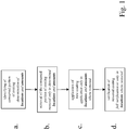
- figure 1 shows in a flow diagram schematically the above steps. In italics important aspects of each step are summarised.
- Figure 2 shows a schematic diagram of a cross section of a coated component (1) having a coating (2) on the surface after service in a gas turbine,.
- any ceramic thermal barrier coating on top of the metallic coating (2) has already been removed by, for example, a mechanical method such as sand blasting or grit blasting possibly supplemented by chemical methods and subsequent cleaning.
- the outer part (3) of the coating is oxidised and the portion below the oxidised coating is consumed (4) and requires replacement.
- the lower portion of the coating (5) is still in acceptable conditions and can be operated again in the gas turbine.
- a diffusion zone (6) is normally formed between the base material of the component (1) and the coating (2).
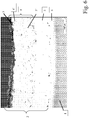
- Figure 3 shows a corresponding cross section micrograph of a coated component (1), having a coating (2) on the surface after service in a gas turbine.
- the outer part (3) of the coating is oxidised and the portion below the outer part (3) is consumed (4) and requires replacement.
- the lower portion of the coating (5) is still in acceptable conditions and can be operated again in the gas turbine.
- a diffusion zone (6) is formed between the base material of the component (1) and the coating (2).
- the consumed portions of the coating are removed by immersion of the relevant parts into an electrolyte bath and by applying a cell voltage in the range of typically several thousand mV having an anodic current density in the range of 0.5-10 A/dm 2 .
- the electrolyte bath is a 10-20 mass % hydrochloric acid bath at a temperature in the range of 30-50°C.
- the time taken for the electrolytic removal process is adapted to the amount of consumed portion of the coating to be removed. This process can for example be controlled by keeping the anodic current density constant over time and by monitoring the voltage. If the consumed portion of the coating is removed one can detect a change in the voltage and correspondingly stop the process at the optimum moment.
- FIG. 4 is a cross section view of the coated gas turbine component (1) displayed in figure 3 , after selective removal of the consumed portion of the coating. By this means only the portions of the coating, which are in acceptable condition (5) remain.
- a diffusion zone (6) is formed between the base material of the component (1) and the remaining coating (5).
- FIG 5 shows a schematic cross section view of the gas turbine component (1) shown in figure 4 , after application of a new coating (7).
- the entire coating (2) thickness meets the component specific coating zone drawing.
- a diffusion zone (6) is located between the base material of the component (1) and the coating (2).
- Figure 6 finally shows a cross sectional micrograph of a gas turbine component (1) with a coating (2) on the surface of the component, the coating (2) includes several layers as described below.
- the coating (2) was restored as described here in a first gas turbine refurbishment.
- the component was again successfully operated in the gas turbine.
- the micrograph shows the status after completion of the second operation interval.
- the inner layer (5) of the coating system (2) directly adjacent to the diffusion zone (6) on the component (1) surface is the original unrestored coating of the coating.
- a second layer (8) of coating was applied.
- the outer portion (3) of this layer was oxidised and the portion below (4') the outer portion (3) was consumed.
- the inner portion (5') of the second coating layer after service exposure (8) and the original coating (5) have protected the component during a second operation period.
Landscapes
- Engineering & Computer Science (AREA)
- Chemical & Material Sciences (AREA)
- Mechanical Engineering (AREA)
- Materials Engineering (AREA)
- General Engineering & Computer Science (AREA)
- Physics & Mathematics (AREA)
- Plasma & Fusion (AREA)
- Chemical Kinetics & Catalysis (AREA)
- Metallurgy (AREA)
- Organic Chemistry (AREA)
- Turbine Rotor Nozzle Sealing (AREA)
Description
- The present invention relates to the field of restoration of coated components of gas turbines wherein the coatings include metallic coatings and coating systems having at least a metallic coating and wherein the coating that has to be restored includes a consumed portion. Throughout this specification the term metallic coating is used to generically describe metallic overlays, diffusion and bond coatings.
- Components such as turbine blades, vanes or structural parts operating in the hot gas path environment of a gas turbine engine can be subjected to high temperature, thermal cycling as well as degrading environments that promote oxidation and corrosion. In order to prevent or at least minimise oxidation and hot gas corrosion it is common practice to apply a metallic coating or a combination of a metallic and a ceramic coating to the surface of the component, wherein the ceramic coating is a thermal barrier coating (TBC). The coatings can result in improved efficiency of the engine by enabling an increase in operating temperatures or alternatively a reduction in cooling air consumption.
- Protective coatings can comprise a metallic coating applied to the component surface, to form a bond coating, or inner metallic coating, and an insulating ceramic outer layer, applied directly onto the bond coat, to form a TBC outer coating that can be made of zirconia stabilized with yttria. Alternatively only metallic coatings can be formed, also in combinations with other coatings.
- Ni, Al and Cr, or Co, Ni, Al and Cr or Pt and Al based alloys can be used to form metallic coatings. Coatings can also take the form of MAl wherein M is at least one element selected from Fe, Ni, and Co and comprises, for example MAl, MAlY, MCrAl, MCrAlY. Another class of coatings are diffused aluminide coatings. The coatings may consist of one or more layers distinguished by their chemical or physical properties, and e.g. one layer of the metallic coating system is of MCrAI(X) type, where M is an element selected from the group containing Ni, Co, Fe and combinations thereof; X is an element selected from the group consisting of Y, Ta, Si, Hf, Ti, Zr, B, C and combinations thereof. Another possibility is that one layer of the metallic coating can be an aluminide, noble-metal-aluminide, noble metal-nickel-aluminide or the like.
- The metallic coatings can be applied by vapour deposition, such as PVD, CVD, or thermal spray methods, atmospheric spray methods, sputtering, cathodic arc, and electron beam, as well as by plasma spray processes. Coating composition, microstructure and thickness are controlled by processing parameters. Diffused aluminide coatings have been applied by a variety of methods including, as used in the art, pack cementation, above the pack, vapour phase, chemical vapour deposition and slurry coating processes. The thickness and composition of the end product coating can be controlled by varying coating time, coating temperature and activity of the coating materials and process. Incorporating such elements as Pt, Rh, Pd, Cr, Si, Hf, Zr, and/or Y often enhances the performance of such coatings. With either type of metallic coating, elements of the coating interdiffuse with an article substrate during processing or operation or both yielding a diffusion zone between the metallic coating and the underlying article substrate. The diffusion zone is considered to be part of the metallic coating. As used herein, the term inner metallic coating is intended to mean at least a portion of the remaining inner metallic coating and such diffusion zone between the metallic coating and the underlying article substrate.
- For gas turbine engine applications, the materials and processing methods chosen for the coating system are selected to provide resistance to spallation of the ceramic outer layer during thermal cycling of the engine as well as resistance to the oxidizing and corrosive environment in the case of a spallation event. During normal engine operation after time, the coatings, including the metallic coating and the ceramic outer layer, will degrade (preferably or particularly) in certain surface areas most subject to operating conditions and environmental stress, the degradation may also depend on the local quality of the coating at these locations. The metallic coating has been observed to be consumed by thermally grown oxides (degradation), consumption of reservoir phases and it has been observed to interdiffuse with a component substrate in such surface areas during operation to the extent that its protective ability has been reduced below an acceptable level, necessitating the removal and reapplication of a protective coating. Therefore, throughout this specification the term consumed portion of the metallic coating is used to describe that part of the metallic coating that is consumed by above-described processes including degradation, depletion (consumption of reservoir phases) and interdiffusion. The consumed portion represents the amount of the metallic coating that has been consumed.
- A current practice in such repair is to remove the entire coating including the metallic coating, optionally along with its zone of diffusion with the component substrate, and the outer ceramic layer. This usually leads to a reduction of the wall thickness. After any required repair of the component structure, the entire coating, including a new metallic coating and a new outer ceramic coating, is reapplied. However, that type of coating system removal, in which the metallic coating is removed, will lead to thinning of component walls and reduce the number of possible repairs of the component, which is an undesirable cost factor. Further the complete removal increases throughput time for the repair process.
- Stripping techniques disclosed in the prior art are not fully satisfactory, insofar as normally the entire coating is removed before a new coating can be applied, irrespective if the entire coating was consumed or not, or if the coating degradation was inhomogeneously distributed over the component surface. This is expensive and bears the risk of reducing the wall thickness of the underlying base material, since the base material is exposed to the abrasive treatment or aggressive stripping media prior to, subsequent or combined with mechanical treatment. Furthermore, reapplying the entire coating thickness is also more expensive and requires more time than replacing only the consumed portion of the coating.
-
US 4339282 andUS 4944807 for example disclose specific etching baths into which the component of which the coating is to be removed can be immersed. In both cases the aim is to remove the full coating structure of the whole component in order to apply a new coating afterwards. -
US 4894130 discloses a method for removal of such coatings in which the cleaned and activated component is immersed into an electrolyte bath and removal of the full coating layer takes place by applying an electric potential between the component and a cathode. - Another approach, disclosed in the prior art, involves local repair of coatings.
US 6042880 for example discloses a method for complete removal of the ceramic TBC layer in local areas only in a manner such that the bond coat layer, i.e. the metallic coating layer is essentially not affected by the removal process and therefore does not have to be completely reconstituted. Another method is disclosed inEP 0713957 , here the entire coating structure is completely removed from certain areas such that the actual component material is uncovered and subsequently in these areas a new coating is built up. - This is appropriate if the coating is only deteriorated in a discrete location.
- However, in general the metallic coating on the entire component surface is affected to some degree, since the entire component surface is exposed to the hot gas during operation of the gas turbine. Consequently, even when an inhomogeneous distribution of coating deterioration is present, the coating is consumed to some degree on the entire surface, but not within the entire thickness.
- Most of the processes known from the state-of-the-art (see for example
US 2005/0235493 ,EP 1 798 302EP 1 927 677EP 1 408 134 - Therefore, a technique, which is able to restore the consumed portion of the coating, over the entire coated area, would be of great benefit.
- The prior art processes lack the following features:
- A simple and cheap method to determine the thickness (e.g. amount) of consumed portions of the coating, that require replacement;
- A method for removing the coating, that can be controlled to such an extent that only the consumed portion of the coating is removed and the underlying substrate is not affected. This decreases the number of potential restoration processes.
- A means of assessing the overall coating quality after restoration of the coating with undamaged inner coatings.
- A combination of these three points is necessary for successful and economic application of customized coating restoration.
- The object of the present invention is therefore to provide an improved, simple and cheap method for the restoration of consumed portions of coatings of the above type, applied to metallic components, for example of gas turbines or combustion chambers. In particular the present invention relates to restoration of normally just the outer portion of coatings for components with undamaged inner portions of coatings and intact substrate (base metal).
- The present invention correspondingly provides the method of
claim 1 for restoration of a consumed portion of a metallic coating or a metallic coating system of a component. One of the concepts of the present invention consists in a targeted manner, in a first step, of determining in detail where the metallic coating is consumed, to what extent (up to which thickness) it is consumed and if it needs to be replaced. Correspondingly in this first step the component to be restored is analysed and the amount of consumed metallic coating which is to be replaced (the thickness thereof) is determined, preferably in spatially resolved manner, i.e. in a manner such that the consumed portions of the metallic coating are identified as a function of the location on the component. - In a second step, again in a targeted manner, based on the collected data in the first step, the consumed portion of the metallic coating is removed, only to the extent (thickness) as necessary. Normally in this step the entire thickness of the metallic coating is not removed but rather only a fraction thereof, which is exposed towards the surface side. Normally in this step at least the diffusion zone of the metallic coating layer remains intact.
- Subsequently, a new metallic coating portion is applied onto the component to where the consumed portion of the metallic coating has been removed in a manner at least compensating for the coating removed in the previous step. The new metallic coating can be applied over the entire surface areas to be coated. The application of new metallic coating is preferably tailored such that the amount of coating applied is a function of the location so as to compensate for the coating removed in the second step. The final target of this third step is to reconstitute the metallic coating layer so as to be homogeneous and intact to an extent that, for example, an optional ceramic thermal barrier coating can be applied as a top coating.
- It is one particular gist of the present invention to remove the metallic coating on the entire coated surface of the component. In other words wherever a metallic coating is present on the component at all (sometimes parts of the component such as the root sections are not coated), it shall be at least partially removed, typically not the whole thickness but a fraction thereof. The removed amount is not the same for the entire coated surface, but it depends as a function of location on the component, based on the result of an identification step, in which the consumed portion (the necessary removal thickness) of the metallic coating is determined using non-destructive analysis techniques as a function of location on the component. Typically this is not possible visually but needs to be carried out by specific methods as outlined below. Alternatively, or in addition to that, it is possible to determine the necessary removal thickness as a function of location using destructive techniques on representative components.
- According to the invention, this removal of the metallic coating in a varying thickness as a function of location on the component takes place using electrolytic stripping. This is done by using specifically tailored counter electrodes, wherein the tailoring of the counter electrodes is carried out in accordance with the results of the identification step. In a nutshell this means that the counter electrode is structured and/or spatially arranged with respect to the component such that the electrical field between the component and the counter electrode as well as the corresponding removal process depends on the location. The aim is to remove as little as possible but as much as necessary of the metallic coating as identified in the identification step. Generally, the metallic coating is used/consumed on the entire component surface at least partially;, therefore typically wherever metallic coating is present on the component it will be at least partially removed in this process. However, preferably it will at no location be completely removed, if not absolutely necessary, such that preferentially the diffusion zone remains intact.
- In contrast to the state-of-the-art, where after visual inspection of true local damages local removal of the metallic coating and subsequent restoration thereof takes place, the presently proposed method is a particularly tailored method for partially (i.e. not entire thickness) coating removal from the entire surface. The removal of the metallic coating on the location, i.e. depending on the location the metallic coating will be removed only to a limited extent, up to substantially, preferably however at no location completely.
- In an optional fourth step of the proposed method the quality of the reconstituted (metallic) coating is checked. If during this step a quality defect is found, step c. can be repeated.
- As mentioned above, preferentially wherever metallic coating is present on the component, it is at least partially removed in step b. leading to an at least partial reduction of the thickness of the entire metallic coating on the component as a result of step b..
- It should generally be noted that prior to carrying out the above method should a ceramic coating layer be present on top of the metallic coating layer, optionally the component can be prepared by removal of this ceramic coating layer. The removal of the ceramic (thermal barrier) coating layer is normally carried out by using mechanical or chemical removal methods. One method is for example grit blasting of the component to remove the ceramic coating layer. After the removal of the ceramic coating layer normally the component is rinsed and cleaned. If necessary cleaning can be supplemented by chemical cleaning treatments for example by immersion into an acid bath and/or an alkaline bath.
- As concerns the removal step b. this can be followed by a cleaning step (rinsing, brushing and the like) and prior to the initiation of the deposition step c. for the new metallic layer the exposed surface can be prepared/activated by chemical and/or mechanical methods.
- According to the invention, in step a. the amount, and/or also the condition, and the associated location of total coated surface, is determined by using one or several non-destructive techniques, preferably selected from the group of: infrared thermography, X-ray fluorescence spectroscopy, ultrasonic or eddy current techniques or combinations thereof. For example an x-ray gun, which can be mounted on a robot can be used to determine by monitoring the variances in aluminium/chromium content of the coating layer whether coating is consumed or not. It should be noted that it is not necessary to carry out the identification step for each and every component to be reconstituted. It is for example in case of blades sufficient to carry out this identification step for one or a few of the blades per row, and subsequently the complete set of blades of the whole row can be subjected to the removal and reconstitution process, as the blades of a row are in a comparable condition and therefore show a similar degradation pattern.
- According to the invention, in step b. the consumed portion of the metallic coating is removed by an electrolytic method comprising the steps of:
- b1. immersing the component in an electrically conductive bath,
- b2. electrically contacting the component and a counter electrode, in the bath,
- b3. applying a potential between the component and the counter electrode, such that the component functions as an anode and the counter electrode as a cathode,
- b4. controlling the potential between the anode and the cathode and measuring the current in order to monitor the coating removal or controlling the current between the anode and the cathode and measuring the voltage in order to monitor the coating removal; and
- b5. stopping the coating removal of step b4. based on the monitoring of the coating removal.
- Electrochemical stripping as such is known from the state-of-the-art (see for
example EP 1 010 782 ,EP 1 094 134 - Preferentially, the electrically conductive liquid bath is an aqueous acidic solution, preferably comprising HCl. Most preferred it is an aqueous hydrogen chloride solution, i.e. an aqueous solution of HCl, which contains 2-30 mass % hydrogen chloride.
- Preferably at least when the potential is applied, the electrically conductive liquid bath has a temperature between room temperature and 80°C. It is further preferred that the electrically conductive liquid bath contains one or more of the following additional constituents: accelerators, inhibitors, pH buffers, anti-settling agents, anti-foaming agents, dispersants, wetting agents, surfactants and stabilizers.
- Furthermore, the electrically conductive bath can be agitated at least when the potential is applied.
- According to a further embodiment, either during step b. or subsequent to step b. the amount (i.e. the thickness), and/or the condition and the associated location of the total coated surface is determined by using one or several non-destructive techniques, preferably selected from the group of: infrared thermography, X-ray fluorescence spectroscopy, ultrasonic or eddy current techniques or combinations thereof.
- According to a still further preferred embodiment of the proposed method, in step c. the new coating is applied to a thickness (identifying the consumed portion) as determined in step a. by a thermal spray technique, a gas phase deposition such as chemical or physical vapour deposition or modifications thereof, or a slurry technique or combinations/sequences of these methods.
- Preferably, the thermal spray technique is high velocity oxy fuel spraying, atmospheric plasma spraying, vacuum plasma spraying or low vacuum plasma spraying.
- Preferentially, in step d. the quality of the restored metallic coating is controlled by non-destructive techniques. These non-destructive techniques can for example be selected from the group of: thermography, X-ray fluorescence spectroscopy, ultrasonic or eddy current techniques or combinations thereof. Preferably, the same method and apparatus is used as is used for step a.
- As mentioned above, typically the component is a gas turbine component (blade, vane, structural parts, etc). Typically such a gas turbine component consists of a Ni, Co, or Fe based superalloy or of a Ti based superalloy or of combinations thereof.
- It is possible that the proposed method is applied in a situation where the coating consists of one or more layers which are distinguished by their chemical or physical properties, wherein preferably at least one layer of the metallic coating is of MCrAI(X) type, where M is an element selected from the group containing Ni, Co, Fe and combinations thereof; X is an element selected from the group consisting of Y, Ta, Si, Hf, Ti, Zr, B, C and combinations thereof and/or wherein at least one layer of the metallic coating system is an aluminide, noble-metal-aluminide, noble metal-nickel-aluminide or combinations thereof.
- As mentioned above, it is preferred that the new coating is applied in a manner compensating for the removed consumed portion of the coating. This is made possible by configuring and arranging of, in step b., the geometry and/or the material of the counter electrode in such a way that metallic coating is mainly or selectively removed in the locations determined in step a. This is preferably possible by the configuring and arranging of the geometry of the counter electrode such that the distance between counter electrode and the article is larger in locations where less coating shall be removed. The size and/or the structure/surface and/or the position and/or the topology and/or the grid structure/width of the counter electrode can also be adjusted in locations where less or more coating shall be removed. It is for example possible to use a grid or web like counter electrode which allows to adapt the current density on the one hand by adaptation of the grid width and/or by the adjustment of the distance to the surface to be treated. Another advantage associated with the use of a grid or web like counter electrode is the fact that it allows a much more efficient agitation of the stripping medium to achieve a fast and homogeneous stripping reaction.
- In addition to this method, it is possible to prior to step b. mask the component such that the metallic coating is selectively exposed in the regions where consumed portions have to be removed during the step b., i.e. in the locations as determined in step a.. Electroplater's tape, clip-on tooling, inert coatings etc can for example, effect such a masking.
- It is not only possible to remove metallic coating by using electrolytic processes, but also to apply the new coating using galvanic deposition. Along this line, according to another embodiment of the proposed method, in step c. the new coating is applied with a thickness as determined in step a. using a galvanic deposition process. Also in this case preferably the geometry and the material (or any other property leading to locally different adapted galvanic processes) of the counter electrode is configured and arranged such that metallic coating is selectively deposited on the locations to be reconstituted. The geometry of the counter electrode can for example be configured and arranged such that the distance between the counter electrode and the article is larger on locations where less coating shall be reconstituted (galvanically deposited) and/or the size and/or the structure/surface and/or the position and/or the topology and/or the grid structure/width of the electrode is correspondingly adapted in locations where coating shall be reconstituted. It should be noted that in cases where, for the removal of the coating, an electrolytic process was already used using a specifically tailored counter electrode, that same counter electrode geometry can be used, for the deposition process, as a cathode leading to homogeneous coating thickness restoration.
- Further embodiments of the present invention are outlined in the dependent claims.
- In the accompanying drawings preferred embodiments of the invention are shown in which:
- Figure 1
- is a flow diagram of the steps of the proposed method;
- Figure 2
- is a schematic diagram of a cross section of a coated component after operation in a gas turbine;
- Figure 3
- is a cross sectional view of a coated component after operation in a gas turbine;
- Figure 4
- is a cross section view of the coated gas turbine component shown in
Figure 2 after selective removal of the consumed portion of the coating; - Figure 5
- is a cross section view of the gas turbine component displayed in
Figure 4 after application of new coating; and - Figure 6
- is a cross sectional view of a micrograph of a gas turbine component with a coating on the component surface wherein the coating includes several layers and was restored as described in the present innovation in a gas turbine refurbishment.
- Generally stated, the present invention provides a customized repair that overcomes the problems inherent to prior art and involves the following steps:
- a. Identifying the portion of the coating, which is consumed as a function of location on the component. This is achieved by one or more non-destructive techniques such as, but not limited to: thermography, X-ray fluorescence spectroscopy, ultrasonic or eddy current investigations. The integrity of the component below the coating can be verified using the same methods. Alternatively, in order to assess coating quality representative members of one row of components can be additionally investigated by destructive techniques.
- b. Removing by means of a process at least the consumed portions of the coating, preferably only the consumed portion. According to the invention, this is achieved by electrolytic stripping, i.e. immersing the component in an electrolytic bath and applying a potential between the component (anode) and a cathode. The electric current (or the voltage depending on the control) changes during the stripping process depending on the amount and condition of overall coating. Consequently, the stripping can be stopped at the previously determined desired end point. If necessary, specific locations of the component can be protected by masking during the stripping process. This allows locally varying degrees of coating removal, according to a previously defined pattern for coating removal.
- c. Applying a new coating, such that the thickness of the remaining coating, plus the thickness of the newly applied coating add up to the thickness distribution according to the component specific coating zone drawing.
- d. Optionally quality controlling to verify if the coating restoration fulfils the requirements. The quality control is achieved by non-destructive techniques, as described in section a.
- Referring to the drawings, which are for the purpose of illustrating preferred embodiments of the invention and not for the purpose of limiting the scope of the invention
figure 1 shows in a flow diagram schematically the above steps. In italics important aspects of each step are summarised. -
Figure 2 shows a schematic diagram of a cross section of a coated component (1) having a coating (2) on the surface after service in a gas turbine,. In the situation shown in this figure any ceramic thermal barrier coating on top of the metallic coating (2) has already been removed by, for example, a mechanical method such as sand blasting or grit blasting possibly supplemented by chemical methods and subsequent cleaning. The outer part (3) of the coating is oxidised and the portion below the oxidised coating is consumed (4) and requires replacement. The lower portion of the coating (5) is still in acceptable conditions and can be operated again in the gas turbine. A diffusion zone (6) is normally formed between the base material of the component (1) and the coating (2). -
Figure 3 shows a corresponding cross section micrograph of a coated component (1), having a coating (2) on the surface after service in a gas turbine. The outer part (3) of the coating is oxidised and the portion below the outer part (3) is consumed (4) and requires replacement. The lower portion of the coating (5) is still in acceptable conditions and can be operated again in the gas turbine. A diffusion zone (6) is formed between the base material of the component (1) and the coating (2). - Such a component can be subjected to the proposed method using the above steps. By means of
figure 4 and figure 5 it shall be illustrated what happens to the metallic coating during these steps. - After locating consumed portions of a coating, as shown in
figure 2 , the consumed portions of the coating are removed by immersion of the relevant parts into an electrolyte bath and by applying a cell voltage in the range of typically several thousand mV having an anodic current density in the range of 0.5-10 A/dm2. The electrolyte bath is a 10-20 mass % hydrochloric acid bath at a temperature in the range of 30-50°C. The time taken for the electrolytic removal process is adapted to the amount of consumed portion of the coating to be removed. This process can for example be controlled by keeping the anodic current density constant over time and by monitoring the voltage. If the consumed portion of the coating is removed one can detect a change in the voltage and correspondingly stop the process at the optimum moment. Alternatively it is possible to keep the cell voltage constant and monitor the anodic current density. The anodic current density can also be monitored for pronounced changes that indicate that the consumed portion of the coating has been removed sufficiently to expose the metallic coating that is not consumed. The result is a situation as shown infigure 4 , which is a cross section view of the coated gas turbine component (1) displayed infigure 3 , after selective removal of the consumed portion of the coating. By this means only the portions of the coating, which are in acceptable condition (5) remain. A diffusion zone (6) is formed between the base material of the component (1) and the remaining coating (5). - After this the coating layer is reconstituted wherever it had been removed, leading to a situation as shown in
figure 5 , which shows a schematic cross section view of the gas turbine component (1) shown infigure 4 , after application of a new coating (7). The entire coating (2) thickness meets the component specific coating zone drawing. A diffusion zone (6) is located between the base material of the component (1) and the coating (2). -
Figure 6 finally shows a cross sectional micrograph of a gas turbine component (1) with a coating (2) on the surface of the component, the coating (2) includes several layers as described below. The coating (2) was restored as described here in a first gas turbine refurbishment. The component was again successfully operated in the gas turbine. The micrograph shows the status after completion of the second operation interval. - The inner layer (5) of the coating system (2) directly adjacent to the diffusion zone (6) on the component (1) surface is the original unrestored coating of the coating. During the restoration according to the invention a second layer (8) of coating was applied. In the second operation interval of the component in the gas turbine, the outer portion (3) of this layer was oxidised and the portion below (4') the outer portion (3) was consumed. The inner portion (5') of the second coating layer after service exposure (8) and the original coating (5) have protected the component during a second operation period.
- A used gas turbine rotating blade, the substrate of which was based on a conventional superalloy (as known for example from
US 4,643,782 ,EP 0 208 645 orEP 0 914 483 ) coated with a metallic coating based on MCrAlY, was subjected to the following treatment: - the consumed portion of the entire metallic coating of the blade was determined as a function of location on the blade, wherein the identification was performed by using infrared thermography and x-ray fluorescence spectroscopy;
- only the consumed portion (i.e. only up to the thickness that was consumed) was removed as a function of the location as identified above over the entire coated surface area.
This step was carried out using an electrolytic method by immersing the component in an aqueous acidic solution, with a concentration of HCl of approx. 12 mass % and at a temperature of 35°C, and by electrically contacting the component and a counter electrode, both immersed in the acidic bath. The geometry of the counter electrode was configured and arranged such that the distance between the counter electrode and the component was larger in locations where less coating was to be removed in accordance with the inspection step and in locations where more coating was to be removed the width of the grid structure and the distance to the counter electrode was adjusted correspondingly.
A potential of approx. 140 mV between the component and this specifically tailored counter electrode was applied and controlled between anode and cathode during the removal process and the current was constantly measured in order to monitor the coating removal process. The coating removal was stopped based on the monitoring of the coating removal and based on the target removal thickness according to the identification step.
After this removal treatment over the entire component surface, the metallic layer (wherever present on the component at all) was removed partially but at no place completely. The removal thickness was just as determined in the identification step. - Subsequently, a new metallic coating was applied using electrolytic deposition and using the same counter electrode geometry as for removal in a manner just compensating for the coating removed in the preceding steps.
-
- 1
- component, substrate
- 2
- metallic coating
- 3
- outer oxidised part of metallic coating
- 4
- consumed part of metallic coating
- 5
- intact part of metallic coating
- 6
- diffusion zone of metallic coating
- 7
- new part (layer) of metallic coating
- 8
- second coating layer after service exposure
Claims (17)
- A method for restoration of a metallic coating (2) of a component (1), wherein the coating (2) includes a consumed portion (3, 4), the method comprising the steps of:a. identifying the consumed portion (3, 4) as a function of location on the component (1), wherein the identification is performed by using one or several non-destructive techniques;b. removing essentially only the consumed portion (3, 4) as a function of the location as identified in step a., wherein removal is carried out using an electrolytic method comprising the steps of:b1. immersing the component in an electrically conductive liquid bath;b2. electrically contacting the component and a counter electrode, which are immersed in said bath;b3. applying a potential between the component and said counter electrode, such that the component functions as an anode and the counter electrode as a cathode;b4. controlling the potential between anode and cathode and measuring the current in order to monitor the coating removal or controlling the current between the anode and the cathode and measuring the voltage in order to monitor the coating removal; andb5. stopping the coating removal of step b4. based on the monitoring of the coating removal;wherein in step b. the geometry and the material of the counter electrode for electrolytic removal is configured and arranged to selectively remove metallic coating (2) as a function of the location as identified in step a.,c. applying new metallic coating (7) in a manner at least compensating for the coating removed in step b..
- The method according to claim 1, wherein, wherever metallic coating (2) is present on the component (1), it is at least partially removed in step b. leading to an at least partial reduction of the thickness of the entire metallic coating (2) on the component (1) as a result of step b..
- The method according to claim 1 or 2, further including after step c. the following step d.:d. verifying the quality of the restored metallic coating (2).
- The method according to claim 1, 2 or 3, wherein step a. further includes determining the condition of either consumed (3, 4) or unconsumed or both consumed (3, 4) and unconsumed portions of the metallic coating (2).
- The method according to any of the preceding claims, wherein the identifying or determination of step a. is at least partly performed by using one or several non-destructive techniques, selected from the group of: infrared thermography, X-ray fluorescence spectroscopy, ultrasonic or eddy current techniques or combinations thereof.
- The method according to any of the preceding claims, wherein the amount of metallic coating (2) to be replaced is also determined on at least one representative component by destructive techniques, such as, but not limited to, metallographic investigations.
- The method according to any of the preceding claims, wherein the electrically conductive liquid bath is an aqueous acidic solution, preferably comprising HCl as the main active constituent, wherein preferably the concentration of HCl is in the rage of 2-30 mass %.
- The method according to any of the preceding claims, wherein the electrically conductive liquid bath has a temperature between room temperature and 80°C, and/or wherein the electrically conductive liquid bath contains one or more of the following additional constituents: accelerators, inhibitors, pH buffers, anti-settling agents, anti-foaming agents, dispersants, wetting agents, surfactants and stabilizers.
- The method according to any of the preceding claims, wherein the electrically conductive liquid bath is agitated at least when the potential is applied.
- The method according to any of the preceding claims, wherein subsequent to or concomitant to step b. the amount, and/or the condition and the associated location of the total coated surface is determined by using one or several non-destructive techniques, preferably selected from the group of: infrared thermography; X-ray fluorescence spectroscopy, ultrasonic or eddy current techniques or combinations thereof.
- The method according to any of the preceding claims, wherein in step c. the amount of the applied new coating is a function of the identification or determination of step a. and the application of the new metallic coating is by a thermal spray technique, wherein preferably the thermal spray technique is high velocity oxy fuel spraying, atmospheric plasma spraying, vacuum plasma spraying or low vacuum plasma spraying, a gas phase deposition such as chemical or physical vapour deposition or modifications thereof, or a slurry technique or combinations of these methods.
- The method according to any of the preceding claims, wherein in step d. the quality of the restored metallic coating is controlled by non-destructive techniques, preferably selected from the group of: infrared thermography, X-ray fluorescence spectroscopy, ultrasonic or eddy current techniques or combinations thereof.
- The method according to any of the preceding claims, wherein the component is a gas turbine component, wherein preferably the gas turbine component, at least on the concerned surface region, consists of a Ni, Co, or Fe based superalloy or of a Ti based superalloy.
- The method according to any of the preceding claims, wherein the metallic coating (2) consists of one or more layers, which are distinguished by their chemical or physical properties, and wherein preferably at least one layer of the metallic coating is of MCrAI(X) type, where: M is an element selected from the group containing Ni, Co, Fe and combinations thereof; X is an element selected from the group consisting of Y, Ta, Si, Hf, Ti, Zr, B, C and combinations thereof and/or wherein preferably at least one layer of the metallic coating is an aluminide, noble-metal-aluminide, noble metal-nickel-aluminide and combinations thereof.
- The method according to any of the preceding claims, wherein the geometry of the counter electrode is configured and arranged such that the distance between the counter electrode and the component is larger in locations where less coating shall be removed and in locations where less coating shall be removed the size and/or the structure/surface and/or the position and/or the topology and/or the grid structure/width of the counter electrode is adjusted.
- The method according to any of the preceding claims, wherein prior to step a. a ceramic coating present on the surface of the metallic coating (2) is removed, preferably mechanically removed.
- The method according to any of the preceding claims, wherein in step c. the new coating is applied using a galvanic deposition process and the amount of the new coating applied is a function of the identification or determination of step a., wherein preferably the geometry of the counter electrode is configured and arranged such that the distance between the counter electrode and the component is larger in locations where less coating shall be reconstituted and in locations where coating shall be reconstituted the size and/or the structure/surface and/or the position and/or the topology and/or the grid structure/width of the electrode is adjusted, and wherein most preferably, if for the removal of the coating an electrolytic process was used with a specifically configured and arranged counter electrode, that same counter electrode geometry is used for the deposition.
Priority Applications (1)
| Application Number | Priority Date | Filing Date | Title |
|---|---|---|---|
| EP09782581.4A EP2337875B1 (en) | 2008-09-19 | 2009-09-03 | Method for the restoration of a metallic coating |
Applications Claiming Priority (3)
| Application Number | Priority Date | Filing Date | Title |
|---|---|---|---|
| EP08164681A EP2166125A1 (en) | 2008-09-19 | 2008-09-19 | Method for the restoration of a metallic coating |
| EP09782581.4A EP2337875B1 (en) | 2008-09-19 | 2009-09-03 | Method for the restoration of a metallic coating |
| PCT/EP2009/061422 WO2010031696A1 (en) | 2008-09-19 | 2009-09-03 | Method for the restoration of a metallic coating |
Publications (2)
| Publication Number | Publication Date |
|---|---|
| EP2337875A1 EP2337875A1 (en) | 2011-06-29 |
| EP2337875B1 true EP2337875B1 (en) | 2017-08-23 |
Family
ID=40344605
Family Applications (2)
| Application Number | Title | Priority Date | Filing Date |
|---|---|---|---|
| EP08164681A Withdrawn EP2166125A1 (en) | 2008-09-19 | 2008-09-19 | Method for the restoration of a metallic coating |
| EP09782581.4A Not-in-force EP2337875B1 (en) | 2008-09-19 | 2009-09-03 | Method for the restoration of a metallic coating |
Family Applications Before (1)
| Application Number | Title | Priority Date | Filing Date |
|---|---|---|---|
| EP08164681A Withdrawn EP2166125A1 (en) | 2008-09-19 | 2008-09-19 | Method for the restoration of a metallic coating |
Country Status (4)
| Country | Link |
|---|---|
| US (1) | US20100072072A1 (en) |
| EP (2) | EP2166125A1 (en) |
| CA (1) | CA2736417A1 (en) |
| WO (1) | WO2010031696A1 (en) |
Families Citing this family (11)
| Publication number | Priority date | Publication date | Assignee | Title |
|---|---|---|---|---|
| JP5517163B2 (en) * | 2010-10-07 | 2014-06-11 | 株式会社日立製作所 | Cooling hole machining method for turbine blade |
| US8636890B2 (en) * | 2011-09-23 | 2014-01-28 | General Electric Company | Method for refurbishing PtAl coating to turbine hardware removed from service |
| US9067294B2 (en) | 2011-11-30 | 2015-06-30 | United Technologies Corporation | Coating removal apparatus |
| EP2969260B1 (en) * | 2013-03-15 | 2018-02-14 | Rolls-Royce Corporation | Anti-fret coating system |
| US9383197B2 (en) | 2014-10-13 | 2016-07-05 | General Electric Company | System and method for measuring cooling of a component |
| EP3098677B1 (en) * | 2015-05-27 | 2019-05-08 | Ansaldo Energia IP UK Limited | Method for machining a component on a multi-axis machine tool driven by an nc-controller and apparatus for conducting said method |
| RU2768908C1 (en) * | 2018-09-20 | 2022-03-25 | Сименс Энерджи, Инк. | Method of cleaning component having heat-insulating coating |
| JP7218201B2 (en) * | 2019-02-13 | 2023-02-06 | アルバックテクノ株式会社 | Method for regenerating oxide film on aluminum parts |
| TR201902731A2 (en) * | 2019-02-23 | 2020-09-21 | Aydeşki̇n Mustafa | Method of coating removal from electrically conductive coated low-e glasses |
| CN110835755A (en) * | 2019-11-12 | 2020-02-25 | 中北大学 | A kind of preparation method of zirconium alloy coating for nuclear |
| US20220290322A1 (en) * | 2021-03-12 | 2022-09-15 | Raytheon Technologies Corporation | Systems, formulations, and methods for removal of diffusion coating from airfoils |
Family Cites Families (19)
| Publication number | Priority date | Publication date | Assignee | Title |
|---|---|---|---|---|
| US4339282A (en) | 1981-06-03 | 1982-07-13 | United Technologies Corporation | Method and composition for removing aluminide coatings from nickel superalloys |
| DE3873038D1 (en) | 1987-12-01 | 1992-08-27 | Bbc Brown Boveri & Cie | METHOD FOR ELECTROLYTICALLY DETACHING A SURFACE PROTECTIVE LAYER HAVING A HIGH CR AND NI AND / OR CO CONTENT FROM THE BASE OF A COMPONENT COMPOSED FROM A SUPER ALLOY. |
| CH674851A5 (en) | 1987-12-01 | 1990-07-31 | Bbc Brown Boveri & Cie | |
| EP0713957A1 (en) | 1994-11-25 | 1996-05-29 | FINMECCANICA S.p.A. AZIENDA ANSALDO | Method of repairing the coating of turbine blades |
| US6176999B1 (en) * | 1998-12-18 | 2001-01-23 | United Technologies Corporation | Feedback controlled stripping of airfoils |
| US6042880A (en) | 1998-12-22 | 2000-03-28 | General Electric Company | Renewing a thermal barrier coating system |
| US6254756B1 (en) * | 1999-08-11 | 2001-07-03 | General Electric Company | Preparation of components having a partial platinum coating thereon |
| US6352636B1 (en) * | 1999-10-18 | 2002-03-05 | General Electric Company | Electrochemical system and process for stripping metallic coatings |
| US6491208B2 (en) * | 2000-12-05 | 2002-12-10 | Siemens Westinghouse Power Corporation | Cold spray repair process |
| JP3905724B2 (en) * | 2001-06-13 | 2007-04-18 | 三菱重工業株式会社 | Repair method for Ni-base alloy parts |
| SE523309E (en) * | 2001-06-15 | 2010-03-02 | Replisaurus Technologies Ab | Method, electrode and apparatus for creating micro- and nanostructures in conductive materials by patterning with master electrode and electrolyte |
| US6599416B2 (en) * | 2001-09-28 | 2003-07-29 | General Electric Company | Method and apparatus for selectively removing coatings from substrates |
| US6701615B2 (en) * | 2002-03-08 | 2004-03-09 | General Electric Company | Inspection and sorting system and method for part repair |
| EP1394360A1 (en) * | 2002-08-23 | 2004-03-03 | Siemens Aktiengesellschaft | Nondestructive method for testing a component as well as method to produce a gas turbine blade |
| US7509735B2 (en) * | 2004-04-22 | 2009-03-31 | Siemens Energy, Inc. | In-frame repairing system of gas turbine components |
| EP1798302A4 (en) * | 2004-08-23 | 2009-12-02 | Toshiba Kk | Method and equipment for repairing rotor |
| DE102004056158B3 (en) * | 2004-11-17 | 2006-03-30 | Siemens Ag | Method for monitoring an electrochemical treatment process and electrode arrangement suitable for this method |
| US20080113163A1 (en) * | 2006-11-14 | 2008-05-15 | United Technologies Corporation | Thermal barrier coating for combustor panels |
| US20090252987A1 (en) * | 2008-04-02 | 2009-10-08 | United Technologies Corporation | Inspection and repair process using thermal acoustic imaging |
-
2008
- 2008-09-19 EP EP08164681A patent/EP2166125A1/en not_active Withdrawn
- 2008-10-27 US US12/258,730 patent/US20100072072A1/en not_active Abandoned
-
2009
- 2009-09-03 CA CA2736417A patent/CA2736417A1/en not_active Abandoned
- 2009-09-03 EP EP09782581.4A patent/EP2337875B1/en not_active Not-in-force
- 2009-09-03 WO PCT/EP2009/061422 patent/WO2010031696A1/en not_active Ceased
Non-Patent Citations (1)
| Title |
|---|
| None * |
Also Published As
| Publication number | Publication date |
|---|---|
| CA2736417A1 (en) | 2010-03-25 |
| US20100072072A1 (en) | 2010-03-25 |
| WO2010031696A1 (en) | 2010-03-25 |
| EP2337875A1 (en) | 2011-06-29 |
| EP2166125A1 (en) | 2010-03-24 |
Similar Documents
| Publication | Publication Date | Title |
|---|---|---|
| EP2166125A1 (en) | Method for the restoration of a metallic coating | |
| JP5036965B2 (en) | Method of repairing coated parts using NiAl bonding coat | |
| EP1531232B1 (en) | Method for repairing a high pressure turbine blade | |
| JP4667714B2 (en) | Removal method of ceramic film | |
| JP4942926B2 (en) | Method of repairing a part using an environmental bond film and the resulting repaired part | |
| EP1076158B1 (en) | Gas turbine component having location-dependent protective coatings thereon | |
| US6274193B1 (en) | Repair of a discrete selective surface of an article | |
| US6933052B2 (en) | Diffusion barrier and protective coating for turbine engine component and method for forming | |
| CA2330218C (en) | Method of removing a thermal barrier coating | |
| JP6126852B2 (en) | Gas turbine component coating and coating method | |
| US6974636B2 (en) | Protective coating for turbine engine component | |
| EP1507022A1 (en) | Thermal barrier coating for reduced sintering and increased impact resistance, and process of making same | |
| EP1944387A1 (en) | System and method for restoring or regenerating an article | |
| US6861157B2 (en) | Article for high temperature service and method for manufacture | |
| US20170369981A1 (en) | Treated gas turbine components and processes of treating gas turbine systems and gas turbine components | |
| KR101928467B1 (en) | Method of rejuvenating a multilayer structure | |
| US20080160213A1 (en) | Method for restoring or regenerating an article | |
| EP1950320B1 (en) | Method for restoring or regenerating an article and restored regenerated article | |
| US20100254820A1 (en) | Article with restored or regenerated structure | |
| WO2009082628A1 (en) | Methods for applying thermal barrier coating systems |
Legal Events
| Date | Code | Title | Description |
|---|---|---|---|
| PUAI | Public reference made under article 153(3) epc to a published international application that has entered the european phase |
Free format text: ORIGINAL CODE: 0009012 |
|
| 17P | Request for examination filed |
Effective date: 20110308 |
|
| AK | Designated contracting states |
Kind code of ref document: A1 Designated state(s): AT BE BG CH CY CZ DE DK EE ES FI FR GB GR HR HU IE IS IT LI LT LU LV MC MK MT NL NO PL PT RO SE SI SK SM TR |
|
| AX | Request for extension of the european patent |
Extension state: AL BA RS |
|
| DAX | Request for extension of the european patent (deleted) | ||
| RAP1 | Party data changed (applicant data changed or rights of an application transferred) |
Owner name: GENERAL ELECTRIC TECHNOLOGY GMBH |
|
| GRAP | Despatch of communication of intention to grant a patent |
Free format text: ORIGINAL CODE: EPIDOSNIGR1 |
|
| RIC1 | Information provided on ipc code assigned before grant |
Ipc: F01D 5/00 20060101ALI20170203BHEP Ipc: F01D 5/28 20060101ALI20170203BHEP Ipc: C23C 4/073 20160101ALI20170203BHEP Ipc: C25F 5/00 20060101ALI20170203BHEP Ipc: C23C 4/02 20060101AFI20170203BHEP |
|
| INTG | Intention to grant announced |
Effective date: 20170310 |
|
| RAP1 | Party data changed (applicant data changed or rights of an application transferred) |
Owner name: ANSALDO ENERGIA SWITZERLAND AG |
|
| GRAS | Grant fee paid |
Free format text: ORIGINAL CODE: EPIDOSNIGR3 |
|
| GRAA | (expected) grant |
Free format text: ORIGINAL CODE: 0009210 |
|
| AK | Designated contracting states |
Kind code of ref document: B1 Designated state(s): AT BE BG CH CY CZ DE DK EE ES FI FR GB GR HR HU IE IS IT LI LT LU LV MC MK MT NL NO PL PT RO SE SI SK SM TR |
|
| REG | Reference to a national code |
Ref country code: GB Ref legal event code: FG4D |
|
| REG | Reference to a national code |
Ref country code: CH Ref legal event code: EP |
|
| REG | Reference to a national code |
Ref country code: AT Ref legal event code: REF Ref document number: 921434 Country of ref document: AT Kind code of ref document: T Effective date: 20170915 |
|
| REG | Reference to a national code |
Ref country code: IE Ref legal event code: FG4D |
|
| REG | Reference to a national code |
Ref country code: FR Ref legal event code: PLFP Year of fee payment: 9 |
|
| REG | Reference to a national code |
Ref country code: DE Ref legal event code: R096 Ref document number: 602009047931 Country of ref document: DE |
|
| PGFP | Annual fee paid to national office [announced via postgrant information from national office to epo] |
Ref country code: FR Payment date: 20170928 Year of fee payment: 9 |
|
| REG | Reference to a national code |
Ref country code: NL Ref legal event code: MP Effective date: 20170823 |
|
| REG | Reference to a national code |
Ref country code: LT Ref legal event code: MG4D |
|
| REG | Reference to a national code |
Ref country code: AT Ref legal event code: MK05 Ref document number: 921434 Country of ref document: AT Kind code of ref document: T Effective date: 20170823 |
|
| PG25 | Lapsed in a contracting state [announced via postgrant information from national office to epo] |
Ref country code: NL Free format text: LAPSE BECAUSE OF FAILURE TO SUBMIT A TRANSLATION OF THE DESCRIPTION OR TO PAY THE FEE WITHIN THE PRESCRIBED TIME-LIMIT Effective date: 20170823 Ref country code: FI Free format text: LAPSE BECAUSE OF FAILURE TO SUBMIT A TRANSLATION OF THE DESCRIPTION OR TO PAY THE FEE WITHIN THE PRESCRIBED TIME-LIMIT Effective date: 20170823 Ref country code: LT Free format text: LAPSE BECAUSE OF FAILURE TO SUBMIT A TRANSLATION OF THE DESCRIPTION OR TO PAY THE FEE WITHIN THE PRESCRIBED TIME-LIMIT Effective date: 20170823 Ref country code: SE Free format text: LAPSE BECAUSE OF FAILURE TO SUBMIT A TRANSLATION OF THE DESCRIPTION OR TO PAY THE FEE WITHIN THE PRESCRIBED TIME-LIMIT Effective date: 20170823 Ref country code: HR Free format text: LAPSE BECAUSE OF FAILURE TO SUBMIT A TRANSLATION OF THE DESCRIPTION OR TO PAY THE FEE WITHIN THE PRESCRIBED TIME-LIMIT Effective date: 20170823 Ref country code: AT Free format text: LAPSE BECAUSE OF FAILURE TO SUBMIT A TRANSLATION OF THE DESCRIPTION OR TO PAY THE FEE WITHIN THE PRESCRIBED TIME-LIMIT Effective date: 20170823 Ref country code: NO Free format text: LAPSE BECAUSE OF FAILURE TO SUBMIT A TRANSLATION OF THE DESCRIPTION OR TO PAY THE FEE WITHIN THE PRESCRIBED TIME-LIMIT Effective date: 20171123 |
|
| PG25 | Lapsed in a contracting state [announced via postgrant information from national office to epo] |
Ref country code: GR Free format text: LAPSE BECAUSE OF FAILURE TO SUBMIT A TRANSLATION OF THE DESCRIPTION OR TO PAY THE FEE WITHIN THE PRESCRIBED TIME-LIMIT Effective date: 20171124 Ref country code: IS Free format text: LAPSE BECAUSE OF FAILURE TO SUBMIT A TRANSLATION OF THE DESCRIPTION OR TO PAY THE FEE WITHIN THE PRESCRIBED TIME-LIMIT Effective date: 20171223 Ref country code: BG Free format text: LAPSE BECAUSE OF FAILURE TO SUBMIT A TRANSLATION OF THE DESCRIPTION OR TO PAY THE FEE WITHIN THE PRESCRIBED TIME-LIMIT Effective date: 20171123 Ref country code: ES Free format text: LAPSE BECAUSE OF FAILURE TO SUBMIT A TRANSLATION OF THE DESCRIPTION OR TO PAY THE FEE WITHIN THE PRESCRIBED TIME-LIMIT Effective date: 20170823 Ref country code: LV Free format text: LAPSE BECAUSE OF FAILURE TO SUBMIT A TRANSLATION OF THE DESCRIPTION OR TO PAY THE FEE WITHIN THE PRESCRIBED TIME-LIMIT Effective date: 20170823 Ref country code: PL Free format text: LAPSE BECAUSE OF FAILURE TO SUBMIT A TRANSLATION OF THE DESCRIPTION OR TO PAY THE FEE WITHIN THE PRESCRIBED TIME-LIMIT Effective date: 20170823 |
|
| PG25 | Lapsed in a contracting state [announced via postgrant information from national office to epo] |
Ref country code: RO Free format text: LAPSE BECAUSE OF FAILURE TO SUBMIT A TRANSLATION OF THE DESCRIPTION OR TO PAY THE FEE WITHIN THE PRESCRIBED TIME-LIMIT Effective date: 20170823 Ref country code: DK Free format text: LAPSE BECAUSE OF FAILURE TO SUBMIT A TRANSLATION OF THE DESCRIPTION OR TO PAY THE FEE WITHIN THE PRESCRIBED TIME-LIMIT Effective date: 20170823 Ref country code: CZ Free format text: LAPSE BECAUSE OF FAILURE TO SUBMIT A TRANSLATION OF THE DESCRIPTION OR TO PAY THE FEE WITHIN THE PRESCRIBED TIME-LIMIT Effective date: 20170823 |
|
| REG | Reference to a national code |
Ref country code: CH Ref legal event code: PL |
|
| REG | Reference to a national code |
Ref country code: DE Ref legal event code: R097 Ref document number: 602009047931 Country of ref document: DE |
|
| PG25 | Lapsed in a contracting state [announced via postgrant information from national office to epo] |
Ref country code: EE Free format text: LAPSE BECAUSE OF FAILURE TO SUBMIT A TRANSLATION OF THE DESCRIPTION OR TO PAY THE FEE WITHIN THE PRESCRIBED TIME-LIMIT Effective date: 20170823 Ref country code: MC Free format text: LAPSE BECAUSE OF FAILURE TO SUBMIT A TRANSLATION OF THE DESCRIPTION OR TO PAY THE FEE WITHIN THE PRESCRIBED TIME-LIMIT Effective date: 20170823 Ref country code: SM Free format text: LAPSE BECAUSE OF FAILURE TO SUBMIT A TRANSLATION OF THE DESCRIPTION OR TO PAY THE FEE WITHIN THE PRESCRIBED TIME-LIMIT Effective date: 20170823 Ref country code: SK Free format text: LAPSE BECAUSE OF FAILURE TO SUBMIT A TRANSLATION OF THE DESCRIPTION OR TO PAY THE FEE WITHIN THE PRESCRIBED TIME-LIMIT Effective date: 20170823 |
|
| REG | Reference to a national code |
Ref country code: IE Ref legal event code: MM4A |
|
| REG | Reference to a national code |
Ref country code: BE Ref legal event code: MM Effective date: 20170930 |
|
| PG25 | Lapsed in a contracting state [announced via postgrant information from national office to epo] |
Ref country code: LU Free format text: LAPSE BECAUSE OF NON-PAYMENT OF DUE FEES Effective date: 20170903 |
|
| PLBE | No opposition filed within time limit |
Free format text: ORIGINAL CODE: 0009261 |
|
| STAA | Information on the status of an ep patent application or granted ep patent |
Free format text: STATUS: NO OPPOSITION FILED WITHIN TIME LIMIT |
|
| PG25 | Lapsed in a contracting state [announced via postgrant information from national office to epo] |
Ref country code: IE Free format text: LAPSE BECAUSE OF NON-PAYMENT OF DUE FEES Effective date: 20170903 Ref country code: CH Free format text: LAPSE BECAUSE OF NON-PAYMENT OF DUE FEES Effective date: 20170930 Ref country code: LI Free format text: LAPSE BECAUSE OF NON-PAYMENT OF DUE FEES Effective date: 20170930 |
|
| 26N | No opposition filed |
Effective date: 20180524 |
|
| PG25 | Lapsed in a contracting state [announced via postgrant information from national office to epo] |
Ref country code: SI Free format text: LAPSE BECAUSE OF FAILURE TO SUBMIT A TRANSLATION OF THE DESCRIPTION OR TO PAY THE FEE WITHIN THE PRESCRIBED TIME-LIMIT Effective date: 20170823 Ref country code: BE Free format text: LAPSE BECAUSE OF NON-PAYMENT OF DUE FEES Effective date: 20170930 |
|
| PG25 | Lapsed in a contracting state [announced via postgrant information from national office to epo] |
Ref country code: MT Free format text: LAPSE BECAUSE OF NON-PAYMENT OF DUE FEES Effective date: 20170903 |
|
| PG25 | Lapsed in a contracting state [announced via postgrant information from national office to epo] |
Ref country code: HU Free format text: LAPSE BECAUSE OF FAILURE TO SUBMIT A TRANSLATION OF THE DESCRIPTION OR TO PAY THE FEE WITHIN THE PRESCRIBED TIME-LIMIT; INVALID AB INITIO Effective date: 20090903 |
|
| PG25 | Lapsed in a contracting state [announced via postgrant information from national office to epo] |
Ref country code: FR Free format text: LAPSE BECAUSE OF NON-PAYMENT OF DUE FEES Effective date: 20180930 |
|
| PG25 | Lapsed in a contracting state [announced via postgrant information from national office to epo] |
Ref country code: CY Free format text: LAPSE BECAUSE OF NON-PAYMENT OF DUE FEES Effective date: 20170823 |
|
| PG25 | Lapsed in a contracting state [announced via postgrant information from national office to epo] |
Ref country code: MK Free format text: LAPSE BECAUSE OF FAILURE TO SUBMIT A TRANSLATION OF THE DESCRIPTION OR TO PAY THE FEE WITHIN THE PRESCRIBED TIME-LIMIT Effective date: 20170823 |
|
| PG25 | Lapsed in a contracting state [announced via postgrant information from national office to epo] |
Ref country code: TR Free format text: LAPSE BECAUSE OF FAILURE TO SUBMIT A TRANSLATION OF THE DESCRIPTION OR TO PAY THE FEE WITHIN THE PRESCRIBED TIME-LIMIT Effective date: 20170823 |
|
| PG25 | Lapsed in a contracting state [announced via postgrant information from national office to epo] |
Ref country code: PT Free format text: LAPSE BECAUSE OF FAILURE TO SUBMIT A TRANSLATION OF THE DESCRIPTION OR TO PAY THE FEE WITHIN THE PRESCRIBED TIME-LIMIT Effective date: 20170823 |
|
| PGFP | Annual fee paid to national office [announced via postgrant information from national office to epo] |
Ref country code: DE Payment date: 20240130 Year of fee payment: 15 Ref country code: GB Payment date: 20240130 Year of fee payment: 15 |
|
| PGFP | Annual fee paid to national office [announced via postgrant information from national office to epo] |
Ref country code: IT Payment date: 20240130 Year of fee payment: 15 |
|
| P01 | Opt-out of the competence of the unified patent court (upc) registered |
Effective date: 20240430 |
|
| REG | Reference to a national code |
Ref country code: DE Ref legal event code: R119 Ref document number: 602009047931 Country of ref document: DE |
|
| GBPC | Gb: european patent ceased through non-payment of renewal fee |
Effective date: 20240903 |
|
| PG25 | Lapsed in a contracting state [announced via postgrant information from national office to epo] |
Ref country code: DE Free format text: LAPSE BECAUSE OF NON-PAYMENT OF DUE FEES Effective date: 20250401 |
|
| PG25 | Lapsed in a contracting state [announced via postgrant information from national office to epo] |
Ref country code: GB Free format text: LAPSE BECAUSE OF NON-PAYMENT OF DUE FEES Effective date: 20240903 |
|
| PG25 | Lapsed in a contracting state [announced via postgrant information from national office to epo] |
Ref country code: IT Free format text: LAPSE BECAUSE OF NON-PAYMENT OF DUE FEES Effective date: 20240903 |