EP2337375A1 - Automatic environmental acoustics identification - Google Patents
Automatic environmental acoustics identification Download PDFInfo
- Publication number
- EP2337375A1 EP2337375A1 EP09179748A EP09179748A EP2337375A1 EP 2337375 A1 EP2337375 A1 EP 2337375A1 EP 09179748 A EP09179748 A EP 09179748A EP 09179748 A EP09179748 A EP 09179748A EP 2337375 A1 EP2337375 A1 EP 2337375A1
- Authority
- EP
- European Patent Office
- Prior art keywords
- sound signal
- internal
- microphone
- external
- mic
- Prior art date
- Legal status (The legal status is an assumption and is not a legal conclusion. Google has not performed a legal analysis and makes no representation as to the accuracy of the status listed.)
- Granted
Links
- 230000007613 environmental effect Effects 0.000 title description 2
- 230000005236 sound signal Effects 0.000 claims description 50
- 230000003044 adaptive effect Effects 0.000 claims description 15
- 238000000034 method Methods 0.000 claims description 14
- 238000000605 extraction Methods 0.000 claims description 11
- 230000000694 effects Effects 0.000 claims description 6
- 238000012545 processing Methods 0.000 claims description 5
- 238000012937 correction Methods 0.000 claims description 4
- 241000699670 Mus sp. Species 0.000 claims 4
- 230000001419 dependent effect Effects 0.000 claims 1
- 238000012360 testing method Methods 0.000 description 4
- 210000005069 ears Anatomy 0.000 description 3
- 230000006870 function Effects 0.000 description 3
- 238000012546 transfer Methods 0.000 description 3
- 230000003190 augmentative effect Effects 0.000 description 2
- 210000000988 bone and bone Anatomy 0.000 description 2
- 238000004364 calculation method Methods 0.000 description 2
- 239000000284 extract Substances 0.000 description 2
- 238000001914 filtration Methods 0.000 description 2
- 238000013459 approach Methods 0.000 description 1
- 238000011161 development Methods 0.000 description 1
- 210000000613 ear canal Anatomy 0.000 description 1
- 210000003027 ear inner Anatomy 0.000 description 1
- 238000002592 echocardiography Methods 0.000 description 1
- 210000003128 head Anatomy 0.000 description 1
- 238000005259 measurement Methods 0.000 description 1
- 238000009877 rendering Methods 0.000 description 1
- 230000013707 sensory perception of sound Effects 0.000 description 1
- 230000001629 suppression Effects 0.000 description 1
- 241000215338 unidentified plant Species 0.000 description 1
Images

Classifications
-
- H—ELECTRICITY
- H04—ELECTRIC COMMUNICATION TECHNIQUE
- H04S—STEREOPHONIC SYSTEMS
- H04S7/00—Indicating arrangements; Control arrangements, e.g. balance control
- H04S7/30—Control circuits for electronic adaptation of the sound field
- H04S7/305—Electronic adaptation of stereophonic audio signals to reverberation of the listening space
- H04S7/306—For headphones
Definitions
- the invention relates to a system which extracts a measure of the acoustic response of the environment, and a method of extracting the acoustic response.
- An auditory display is a human-machine interface to provide information to a user by means of sounds. These are particularly suitable in applications where the user is not permitted or not able to look at a display.
- An example is a headphone-based navigation system which delivers audible navigation instructions. The instructions can appear to come from the appropriate physical location or direction, for example a commercial may appear to come from a particular shop. Such systems are suitable for assisting blind people.
- Headphone systems are well known. In typical systems a pair of loudspeakers are mounted on a band so as to be worn with the loudspeakers adjacent to a user's ears. Closed headphone systems seek to reduce environmental noise by providing a closed enclosure around each user's ear, and are often used in noisy environments or in noise cancellation systems. Open headphone systems have no such enclosure.
- the term "headphone” is used in this application to include earphone systems where the loudspeakers are closely associated with the user's ears, for example mounted on or in the user's ears.
- ARA augmented reality audio
- the headphones do not simply reproduce the sound of a sound source, but create a synthesized environment, with for example reverberation, echoes and other features of natural environments. This can cause the user's perception of sound to be externalized, so the user perceives the sound in a natural way and does not perceive the sound to originate from within the user's head.
- Reverberation in particular is known to play a significant role in the externalization of virtual sound sources played back on headphones.
- Accurate rendering of the environment is particularly important in ARA systems where the acoustic properties of the real and virtual sources must be very similar.
- the inventor has realised that a particular difficulty in providing realistic audio environments is in obtaining the data regarding the audio environment occupied by a user. Headphone systems can be used in a very wide variety of audio environments.
- the system according to the invention avoids the need for a loudspeaker driven by a test signals to generate suitable sounds for determining the impulse response of the environment. Instead, the speech of the user is used as the reference signal.
- the signals from the pair of microphones, one external and one internal, can then be used to calculate the room impulse response.
- the calculation may be done using a normalised least mean squares adaptive filter.
- the system may have a binaural positioning unit having a sound input for accepting an input sound signal and to drive the loudspeakers with a processed stereo signal, wherein the processed sound signal is derived from the input sound signal and the acoustic response of the environment.
- the binaural positioning unit may be arranged to generate the processed sound signal by convolving the input sound system with the room inpulse response.
- the input sound signal is a stereo sound signal and the processed sound signal is also a stereo sound signal.
- the processing may be carried out by convolving the input sound system with the room inpulse response to calculate the processed sound signal. In this way, the input sound is processed to match the auditory properties of the environment of the user.
- headphone 2 has a central headband 4 linking the left ear unit 6 and the right ear unit 8.
- Each of the ear units has an enclosure 10 for surrrounding the user's ear - accordingly the headphone 2 in this embodiment is a closed headphone.
- An internal microphone 12 and an external microphone 14 are provided on the inside of the enclosure 10 and the outside respectively.
- a loudspeaker 16 is also provided to generate sounds.
- a sound processor 20 is provided, including reverberation extraction units 22,24 and a binaural positioning unit 26.
- Each ear unit 6,8 is connected to a respective reverberation extraction unit 22,24.
- Each takes signals from both the internal microphone 12 and the external microphone 14 of the respective ear unit, and is arranged to output a measure of the environment response to the binaural positioning unit 26 as will be explained in more detail below.
- the binaural positioning unit 26 is arranged to take an input sound signal 28 and information 30 together with the information regarding the environment response from the reverberation extraction units 22,24. Then, the binaural positioning unit creates an output sound signal 32 based on the measures of the environment response to modify the input sound signal and outputs the output sound signal to the loudspeakers 16.
- the reverberation extraction units 22,24 extract the environment impulse response as the measure of the environment response. This requires an input or test signal. In the present case, the user's speech is used as the test signal which avoids the need for a dedicated test signal.
- the signal from the internal microphone 12 is used as the input signal and the signal from the external microphone 14 is used as the desired signal.
- H e and H i are the transfer functions between the reference speech signal and the signal recorded with the external and internal microphones respectively.
- H e is the desired room impulse response while H i is the result of the bone and skin conduction from the throat to the ear canal.
- H i is typically independent from the environment the user is in. It can be thus measured off-line and used as an optional equalization filter.
- FIG. 1 One of the many possible techniques to identify the room impulse response H e based on the microphone inputs Mic i and Mic e is an adaptive filter, using a Least Mean Square (LMS) algorithm.
- LMS Least Mean Square
- Figure 2 depicts such adaptive filtering scheme.
- x[n] is the input signal and the adaptive filter attempts to adapt filter ⁇ [ n ] to make it as close as possible to the unknown plant w [ n ] , using only x [ n ] , d [ n ] and e[n] as observable signals.
- the input signal x [ n ] is filtered through two different paths, h e [ n ] and h i [ n ], which are the impulse responses of the transfer functions H e and H i respectively.
- the system could be calibrated in an anechoic environment using the same procedure as described above.
- H i is the room independent path to the internal microphone and H e - anechoic the path from the mouth to the external microphone in anechoic conditions. It includes the filtering effect due to the placement of the microphone behind the mouth instead of in front of it. This effect is neglected in the first embodiment, but can be compensated for when a calibration in anechoic conditions is possible.
- the environment impulse response is then used to process the input sound signal 28 by performing a direct convolution of the input sound signal with the room impulse response.
- the input sound signal 28 is preferably a dry, anechoic sound signal and may in particular be a stereo signal.
- the environment impulse response can be used to identify the properties of the environment and this used to select suitable processing.
- the environment impulse response When used in a room, the environment impulse response will be a room impulse response.
- the invention is not limited to use in rooms and other environments, for example outside, may also be modelled. For this reason, the term environment impulse response has been used.
- the environment impulse response is not the only measure of the auditory environment and alternatives, such as reverberation time, may alternatively or additionally be calculated.
- the invention is also applicable to other forms of headphones, including earphones, such as intra-concha or in-ear canal earpieces.
- the internal microphone may be provided on the inside of the ear unit facing the user's inner ear and the external microphone is on the outside of the ear unit facing the outside.
- the sound processor 20 may be implemented in either hardware or software. However, in view of the complexity and necessary speed of calculation in the reverberation extraction units 22,24, these may in particular be implemented in a digital signal processor (DSP).
- DSP digital signal processor
- Applications include noise cancellation headphones and auditory display apparatus.
Landscapes
- Engineering & Computer Science (AREA)
- Multimedia (AREA)
- Physics & Mathematics (AREA)
- Acoustics & Sound (AREA)
- Signal Processing (AREA)
- Stereophonic System (AREA)
- Soundproofing, Sound Blocking, And Sound Damping (AREA)
Abstract
Description
- The invention relates to a system which extracts a measure of the acoustic response of the environment, and a method of extracting the acoustic response.
- An auditory display is a human-machine interface to provide information to a user by means of sounds. These are particularly suitable in applications where the user is not permitted or not able to look at a display. An example is a headphone-based navigation system which delivers audible navigation instructions. The instructions can appear to come from the appropriate physical location or direction, for example a commercial may appear to come from a particular shop. Such systems are suitable for assisting blind people.
- Headphone systems are well known. In typical systems a pair of loudspeakers are mounted on a band so as to be worn with the loudspeakers adjacent to a user's ears. Closed headphone systems seek to reduce environmental noise by providing a closed enclosure around each user's ear, and are often used in noisy environments or in noise cancellation systems. Open headphone systems have no such enclosure. The term "headphone" is used in this application to include earphone systems where the loudspeakers are closely associated with the user's ears, for example mounted on or in the user's ears.
- It has been proposed to use headphones to create virtual or synthesized acoustic environments. In the case where the sounds are virtualized so that listeners perceive them as coming from the real environment, the systems may be referred to as augmented reality audio (ARA) systems.
- In systems creating such virtual or synthesized environments, the headphones do not simply reproduce the sound of a sound source, but create a synthesized environment, with for example reverberation, echoes and other features of natural environments. This can cause the user's perception of sound to be externalized, so the user perceives the sound in a natural way and does not perceive the sound to originate from within the user's head. Reverberation in particular is known to play a significant role in the externalization of virtual sound sources played back on headphones. Accurate rendering of the environment is particularly important in ARA systems where the acoustic properties of the real and virtual sources must be very similar.
- A development of this concept is provided in Härmä et al, "Techniques and applications of wearable augmented reality audio", presented at the AES 114th convention, Amsterdam, March 22 to 25 2003. This presents a useful overview of a number of options. In particular, the paper proposes generating an environment corresponding to the environment the user is actually present in. This can increase realism during playback.
- However, there remains a need for convenient, practical portable systems that can deliver such an audio environment.
- Further, such systems need data regarding the audio environment to be generated. The conventional way to obtain data about room acoustics is to play back a known signal on a loudspeaker and measure the received signal. The room impulse response is given by the deconvolution of the measured signal by the reference signal.
- Attempts have been made to estimate the reverberation time from recorded data without generating a sound, but these are not particularly accurate and do not generate additional data such as the room impulse response.
- According to the invention, there is provided a headphone system according to claim 1 and a method according to claim 9.
- The inventor has realised that a particular difficulty in providing realistic audio environments is in obtaining the data regarding the audio environment occupied by a user. Headphone systems can be used in a very wide variety of audio environments.
- The system according to the invention avoids the need for a loudspeaker driven by a test signals to generate suitable sounds for determining the impulse response of the environment. Instead, the speech of the user is used as the reference signal. The signals from the pair of microphones, one external and one internal, can then be used to calculate the room impulse response.
- The calculation may be done using a normalised least mean squares adaptive filter.
- The system may have a binaural positioning unit having a sound input for accepting an input sound signal and to drive the loudspeakers with a processed stereo signal, wherein the processed sound signal is derived from the input sound signal and the acoustic response of the environment.
- The binaural positioning unit may be arranged to generate the processed sound signal by convolving the input sound system with the room inpulse response.
- In embodiments, the input sound signal is a stereo sound signal and the processed sound signal is also a stereo sound signal.
- The processing may be carried out by convolving the input sound system with the room inpulse response to calculate the processed sound signal. In this way, the input sound is processed to match the auditory properties of the environment of the user.
- For a better understanding of the invention, embodiments of the invention will now be described, purely by way of example, with reference to the accompanying drawings, in which:
-
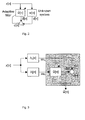
Figure 1 shows a schematic drawing of an embodiment of the invention; -
Figure 2 illustrates an adaptive filter; -
Figure 3 illustrates an adaptive filter as used in an embodiment of the invention; and -
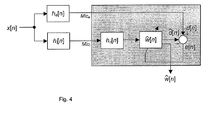
Figure 4 illustrates an adaptive filter as used in an alternative embodiment of the invention. - Referring to
Figure 1 ,headphone 2 has a central headband 4 linking theleft ear unit 6 and theright ear unit 8. Each of the ear units has anenclosure 10 for surrrounding the user's ear - accordingly theheadphone 2 in this embodiment is a closed headphone. Aninternal microphone 12 and anexternal microphone 14 are provided on the inside of theenclosure 10 and the outside respectively. Aloudspeaker 16 is also provided to generate sounds. - A
sound processor 20 is provided, includingreverberation extraction units binaural positioning unit 26. - Each
ear unit reverberation extraction unit internal microphone 12 and theexternal microphone 14 of the respective ear unit, and is arranged to output a measure of the environment response to thebinaural positioning unit 26 as will be explained in more detail below. - The
binaural positioning unit 26 is arranged to take aninput sound signal 28 andinformation 30 together with the information regarding the environment response from thereverberation extraction units output sound signal 32 based on the measures of the environment response to modify the input sound signal and outputs the output sound signal to theloudspeakers 16. - In the particular embodiment described, the
reverberation extraction units - This is done using the microphone inputs using a normalised least mean squared adaptive filter. The signal from the
internal microphone 12 is used as the input signal and the signal from theexternal microphone 14 is used as the desired signal. - The techniques used to calculate the room impulse response will now be described in considerably more detail.
- Consider the reference speech signal produced by the user which will be referred to as x. When in a reverberant environment, the speech signal will be filtered by the room impulse response, and reach the external microphone (signal Mic e). Simultaneously, the speech signal is captured by the internal microphone (signal Mici ) through skin and bone conduction. He and Hi are the transfer functions between the reference speech signal and the signal recorded with the external and internal microphones respectively. He is the desired room impulse response while Hi is the result of the bone and skin conduction from the throat to the ear canal. Hi is typically independent from the environment the user is in. It can be thus measured off-line and used as an optional equalization filter.
- One of the many possible techniques to identify the room impulse response H e based on the microphone inputs Mici and Mice is an adaptive filter, using a Least Mean Square (LMS) algorithm.
Figure 2 depicts such adaptive filtering scheme. x[n] is the input signal and the adaptive filter attempts to adapt filter ŵ[n] to make it as close as possible to the unknown plant w[n], using only x[n], d[n] and e[n] as observable signals. - In the present invention, illustrated in
Figure 3 , the input signal x[n] is filtered through two different paths, he [n] and hi [n], which are the impulse responses of the transfer functions He and Hi respectively. The adaptive filter will find ŵ[n] so as to minimize e[n] =ŵ[n] * Mice [n]- Mici [n] in the least square sense, where * denotes the convolution operation. The resulting filter ŵ[n] is the desired room impulse response between Mici and Mice , and when expressed in the frequency domain to ease notations, we have
- In a further embodiment, the system could be calibrated in an anechoic environment using the same procedure as described above. In this case the resulting filter ŵ anechoic [n], expressed in frequency domain is now

- Hi is the room independent path to the internal microphone and H e-anechoic the path from the mouth to the external microphone in anechoic conditions. It includes the filtering effect due to the placement of the microphone behind the mouth instead of in front of it. This effect is neglected in the first embodiment, but can be compensated for when a calibration in anechoic conditions is possible. In the remainder of this document, He , the path from the mouth to the external microphone, will hence be split in two parts: He-anechoic and He-room , where He-room is the desired room response, such that

- Ŵanechoic can be used as a correction filter

illustrated inFigure 4 , to suppress from the room impulse response the path Hi from the mouth to the error microphone and the part of He which is due to the positioning of the microphone (i.e. He-anechoic ) and keep only He-room as end result. - Indeed, the filter ŵ[n] obtained according to
Figure 4 is, in frequency domain,
- As seen (1) and (3), we obtain

- If we split He according to (2), we finally obtain

- Using the anechoic measurement as correction filter indeed allows the suppression of all contributions not related to the room transfer function to be identified.
- The environment impulse response is then used to process the
input sound signal 28 by performing a direct convolution of the input sound signal with the room impulse response. - The
input sound signal 28 is preferably a dry, anechoic sound signal and may in particular be a stereo signal. - As an alternative to convolution, the environment impulse response can be used to identify the properties of the environment and this used to select suitable processing.
- When used in a room, the environment impulse response will be a room impulse response. However, the invention is not limited to use in rooms and other environments, for example outside, may also be modelled. For this reason, the term environment impulse response has been used.
- Note that those skilled in the art will realise that alternatives to the above approach exist. For example, the environment impulse response is not the only measure of the auditory environment and alternatives, such as reverberation time, may alternatively or additionally be calculated.
- The invention is also applicable to other forms of headphones, including earphones, such as intra-concha or in-ear canal earpieces. In this case, the internal microphone may be provided on the inside of the ear unit facing the user's inner ear and the external microphone is on the outside of the ear unit facing the outside.
- It should also be noted that the
sound processor 20 may be implemented in either hardware or software. However, in view of the complexity and necessary speed of calculation in thereverberation extraction units - Applications include noise cancellation headphones and auditory display apparatus.
Claims (15)
- A headphone system for a user, comprising
a headset (2) with at least one ear unit (6,8), a loudspeaker (16) for generating sound, an internal microphone (12) located on the inside of the ear unit (6,8) for generating an internal sound signal and an external microphone (14) located on the outside of the ear unit (6,8) for generating an external sound signal; and
at least one reverberation extraction unit (22,24) connected to the pair of microphones, arranged to extract the acoustic response of the environment of the headphone system from the internal and the external sound signal recorded as the user speaks. - A headphone system according to claim 1 wherein the acoustic response of the environment calculated by the reverberation extraction unit (22,24) is the environment impulse response calculated using a normalised least mean squares adaptive filter..
- A headphone system according to claim 1 or 2, wherein the adaptive filter in the reverberation extraction unit (22,24) is arranged to seek w [n] so as to minimize e[n] = ŵ [n] * Mice [n]- Mici [n] , where Mice is the external sound signal recorded on the external microphone (14), Mici [n] is the internal sound signal recorded on the internal microphone, [n] is the time index, the minimization is carried out in the least square sense, where * denotes the convolution operation.
- A headphone system according to claim 1 or 2, wherein the adaptive filter in the reverberation extraction unit (22,24) is arranged to seek ŵ [n] so as to minimize e[n] = ŵ[n] * Mice [n] - hc[n] * Mici [n], where Mice is the external sound signal recorded on the external microphone (14), Mici [n] is the internal sound signal recorded on the internal microphone, [n] is the time index, the minimization is carried out in the least square sense, *denotes the convolution operation and hc[n] is a correction to suppress from the room impulse response the effects of the path from the mouth to the internal microphone and the effects of the positioning of the external microphone.
- A headphone system according to any preceding claim having a pair of ear units (6,8), one for each ear of the user, and a pair of reverberation extraction units (22,24), one for each ear unit.
- A headphone system according to any preceding claim, further comprising a binaural positioning unit (26) having a sound input (27) for accepting an input sound signal and a sound output (29) for outputting a processed stereo signal to drive the loudspeakers;,
wherein the processed sound signal is derived from the input sound signal and the acoustic response of the environment. - A headphone system according to claim 6 wherein the binaural positioning unit (26) is arranged to generate the processed sound signal by convolving the input sound signal with an environment impulse response determined by the at least one reverberation extraction unit (22,24).
- A headphone system according to claim 6 or 7 when dependent on claim 5, wherein the input sound signal is a stereo sound signal and the processed sound signal is also a stereo sound signal.
- A method of acoustical processing comprising
providing a headset (2) to a user (18), the headset having at least one ear unit, a loudspeaker for generating sound, an internal microphone forr generating an internal sound signal on the inside of the ear unit and an external microphone located on the outside of the ear unit for generating an external sound signal;
generating an internal sound signal from the internal microphone (12) and an external sound signal from the external microphone (14) whilst the user is speaking; and
extracting the acoustic response of the environment of the headphone system from the internal sound signal and the external sound signal. - A method according to claim 9 wherein the step of extracting the acoustic response of the environment comprises calculating the environment impulse response using a normalised least mean squares adaptive filter.
- A method according to claim 9 or 10, wherein the adaptive filter seeks ŵ[n] so as to minimize e[n] = ŵ[n] * Mic[n]- Mici [n], where Mice is the external sound signal recorded on the external microphone (14), Mici [n] is the internal sound signal recorded on the internal microphone, [n] is the time index, the minimization is carried out in the least square sense, where * denotes the convolution operation.
- A method according to claim 9 or 10, wherein the adaptive filter seeks w [n] so as to minimize e[n] = ŵ[n] * Mice [n] - hc[n] * Mici [n], where Mice is the external sound signal recorded on the external microphone (14), Mici [n] is the internal sound signal recorded on the internal microphone, [n] is the time index, the minimization is carried out in the least square sense, * denotes the convolution operation and hc[n] is a correction to suppress from the room impulse response the effects of the path from the mouth to the internal microphone and the effects of the positioning of the external microphone.
- A method according to any of claims 9 to 12 further comprising
processing an input stereo and the extracted acoustic response to generate a processed sound signal, and
driving the at least one loudspeaker using the processed sound signal. - A method according to any of claims 9 to 13 wherein the step of processing comprises convolving the input sound system with the room impulse response to calculate the processed sound signal.
- A method according to any of claims 9 to 14 wherein the input sound signal is a stereo sound signal and the processed sound signal is also a stereo sound signal.
Priority Applications (3)
| Application Number | Priority Date | Filing Date | Title |
|---|---|---|---|
| EP09179748.0A EP2337375B1 (en) | 2009-12-17 | 2009-12-17 | Automatic environmental acoustics identification |
| US12/970,905 US8682010B2 (en) | 2009-12-17 | 2010-12-16 | Automatic environmental acoustics identification |
| CN201010597877.5A CN102164336B (en) | 2009-12-17 | 2010-12-16 | Head-wearing type receiver system and acoustics processing method |
Applications Claiming Priority (1)
| Application Number | Priority Date | Filing Date | Title |
|---|---|---|---|
| EP09179748.0A EP2337375B1 (en) | 2009-12-17 | 2009-12-17 | Automatic environmental acoustics identification |
Publications (2)
| Publication Number | Publication Date |
|---|---|
| EP2337375A1 true EP2337375A1 (en) | 2011-06-22 |
| EP2337375B1 EP2337375B1 (en) | 2013-09-11 |
Family
ID=42133593
Family Applications (1)
| Application Number | Title | Priority Date | Filing Date |
|---|---|---|---|
| EP09179748.0A Active EP2337375B1 (en) | 2009-12-17 | 2009-12-17 | Automatic environmental acoustics identification |
Country Status (3)
| Country | Link |
|---|---|
| US (1) | US8682010B2 (en) |
| EP (1) | EP2337375B1 (en) |
| CN (1) | CN102164336B (en) |
Cited By (1)
| Publication number | Priority date | Publication date | Assignee | Title |
|---|---|---|---|---|
| EP3441966A1 (en) * | 2014-07-23 | 2019-02-13 | PCMS Holdings, Inc. | System and method for determining audio context in augmented-reality applications |
Families Citing this family (17)
| Publication number | Priority date | Publication date | Assignee | Title |
|---|---|---|---|---|
| US8199942B2 (en) * | 2008-04-07 | 2012-06-12 | Sony Computer Entertainment Inc. | Targeted sound detection and generation for audio headset |
| RU2595943C2 (en) * | 2011-01-05 | 2016-08-27 | Конинклейке Филипс Электроникс Н.В. | Audio system and method for operation thereof |
| AU2012236649A1 (en) * | 2011-03-28 | 2013-10-31 | Ambientz | Methods and systems for searching utilizing acoustical context |
| US9356571B2 (en) * | 2012-01-04 | 2016-05-31 | Harman International Industries, Incorporated | Earbuds and earphones for personal sound system |
| CN102543097A (en) * | 2012-01-16 | 2012-07-04 | 华为终端有限公司 | Denoising method and equipment |
| CN104956689B (en) * | 2012-11-30 | 2017-07-04 | Dts(英属维尔京群岛)有限公司 | For the method and apparatus of personalized audio virtualization |
| US10043535B2 (en) * | 2013-01-15 | 2018-08-07 | Staton Techiya, Llc | Method and device for spectral expansion for an audio signal |
| CN103207719A (en) * | 2013-03-28 | 2013-07-17 | 北京京东方光电科技有限公司 | Capacitive inlaid touch screen and display device |
| CN108605193B (en) | 2016-02-01 | 2021-03-16 | 索尼公司 | Sound output device, sound output method, computer-readable storage medium, and sound system |
| KR102642275B1 (en) | 2016-02-02 | 2024-02-28 | 디티에스, 인코포레이티드 | Augmented reality headphone environment rendering |
| WO2017147428A1 (en) | 2016-02-25 | 2017-08-31 | Dolby Laboratories Licensing Corporation | Capture and extraction of own voice signal |
| EP3453189B1 (en) | 2016-05-06 | 2021-04-14 | Eers Global Technologies Inc. | Device and method for improving the quality of in- ear microphone signals in noisy environments |
| US20170372697A1 (en) * | 2016-06-22 | 2017-12-28 | Elwha Llc | Systems and methods for rule-based user control of audio rendering |
| US10361673B1 (en) | 2018-07-24 | 2019-07-23 | Sony Interactive Entertainment Inc. | Ambient sound activated headphone |
| EP3897386A4 (en) * | 2018-12-21 | 2022-09-07 | Nura Holdings PTY Ltd | AUDIO EQUALIZATION METADATA |
| WO2020131963A1 (en) | 2018-12-21 | 2020-06-25 | Nura Holdings Pty Ltd | Modular ear-cup and ear-bud and power management of the modular ear-cup and ear-bud |
| WO2020180499A1 (en) | 2019-03-01 | 2020-09-10 | Nura Holdings Pty Ltd | Headphones with timing capability and enhanced security |
Citations (5)
| Publication number | Priority date | Publication date | Assignee | Title |
|---|---|---|---|---|
| US20070165879A1 (en) * | 2006-01-13 | 2007-07-19 | Vimicro Corporation | Dual Microphone System and Method for Enhancing Voice Quality |
| US20070297617A1 (en) * | 2006-06-23 | 2007-12-27 | Cehelnik Thomas G | Neighbor friendly headset: featuring technology to reduce sound produced by people speaking in their phones |
| US20080037801A1 (en) * | 2006-08-10 | 2008-02-14 | Cambridge Silicon Radio, Ltd. | Dual microphone noise reduction for headset application |
| GB2441835A (en) * | 2007-02-07 | 2008-03-19 | Sonaptic Ltd | Ambient noise reduction system with a limited family of responses |
| US20090046867A1 (en) * | 2006-04-12 | 2009-02-19 | Wolfson Microelectronics Plc | Digtal Circuit Arrangements for Ambient Noise-Reduction |
Family Cites Families (9)
| Publication number | Priority date | Publication date | Assignee | Title |
|---|---|---|---|---|
| JP2000059876A (en) * | 1998-08-13 | 2000-02-25 | Sony Corp | Sound equipment and headphones |
| US6741707B2 (en) * | 2001-06-22 | 2004-05-25 | Trustees Of Dartmouth College | Method for tuning an adaptive leaky LMS filter |
| US8670570B2 (en) * | 2006-11-07 | 2014-03-11 | Stmicroelectronics Asia Pacific Pte., Ltd. | Environmental effects generator for digital audio signals |
| WO2008095167A2 (en) * | 2007-02-01 | 2008-08-07 | Personics Holdings Inc. | Method and device for audio recording |
| US8081780B2 (en) * | 2007-05-04 | 2011-12-20 | Personics Holdings Inc. | Method and device for acoustic management control of multiple microphones |
| CN101400007A (en) * | 2007-09-28 | 2009-04-01 | 富准精密工业(深圳)有限公司 | Active noise eliminating earphone and noise eliminating method thereof |
| US8477957B2 (en) * | 2009-04-15 | 2013-07-02 | Nokia Corporation | Apparatus, method and computer program |
| US8090114B2 (en) * | 2009-04-28 | 2012-01-03 | Bose Corporation | Convertible filter |
| JP5550456B2 (en) * | 2009-06-04 | 2014-07-16 | 本田技研工業株式会社 | Reverberation suppression apparatus and reverberation suppression method |
-
2009
- 2009-12-17 EP EP09179748.0A patent/EP2337375B1/en active Active
-
2010
- 2010-12-16 CN CN201010597877.5A patent/CN102164336B/en active Active
- 2010-12-16 US US12/970,905 patent/US8682010B2/en not_active Expired - Fee Related
Patent Citations (5)
| Publication number | Priority date | Publication date | Assignee | Title |
|---|---|---|---|---|
| US20070165879A1 (en) * | 2006-01-13 | 2007-07-19 | Vimicro Corporation | Dual Microphone System and Method for Enhancing Voice Quality |
| US20090046867A1 (en) * | 2006-04-12 | 2009-02-19 | Wolfson Microelectronics Plc | Digtal Circuit Arrangements for Ambient Noise-Reduction |
| US20070297617A1 (en) * | 2006-06-23 | 2007-12-27 | Cehelnik Thomas G | Neighbor friendly headset: featuring technology to reduce sound produced by people speaking in their phones |
| US20080037801A1 (en) * | 2006-08-10 | 2008-02-14 | Cambridge Silicon Radio, Ltd. | Dual microphone noise reduction for headset application |
| GB2441835A (en) * | 2007-02-07 | 2008-03-19 | Sonaptic Ltd | Ambient noise reduction system with a limited family of responses |
Cited By (1)
| Publication number | Priority date | Publication date | Assignee | Title |
|---|---|---|---|---|
| EP3441966A1 (en) * | 2014-07-23 | 2019-02-13 | PCMS Holdings, Inc. | System and method for determining audio context in augmented-reality applications |
Also Published As
| Publication number | Publication date |
|---|---|
| US20110150248A1 (en) | 2011-06-23 |
| CN102164336B (en) | 2014-04-16 |
| US8682010B2 (en) | 2014-03-25 |
| CN102164336A (en) | 2011-08-24 |
| EP2337375B1 (en) | 2013-09-11 |
Similar Documents
| Publication | Publication Date | Title |
|---|---|---|
| EP2337375B1 (en) | Automatic environmental acoustics identification | |
| CN107018460B (en) | Binaural headset rendering with head tracking | |
| JP4780119B2 (en) | Head-related transfer function measurement method, head-related transfer function convolution method, and head-related transfer function convolution device | |
| US9615189B2 (en) | Artificial ear apparatus and associated methods for generating a head related audio transfer function | |
| EP3413590B1 (en) | Audio output device, audio output method, program, and audio system | |
| Ranjan et al. | Natural listening over headphones in augmented reality using adaptive filtering techniques | |
| EP2953383B1 (en) | Signal processing circuit | |
| US20040136538A1 (en) | Method and system for simulating a 3d sound environment | |
| US20120128166A1 (en) | Systems, methods, apparatus, and computer-readable media for head tracking based on recorded sound signals | |
| CN112956210B (en) | Audio signal processing method and device based on equalization filter | |
| CN107039029B (en) | Sound reproduction with active noise control in a helmet | |
| JP4904461B2 (en) | Voice frequency response processing system | |
| EP3837863B1 (en) | Methods for obtaining and reproducing a binaural recording | |
| Schepker et al. | Subjective sound quality evaluation of an acoustically transparent hearing device | |
| EP2822301B1 (en) | Determination of individual HRTFs | |
| JP2001346298A (en) | Binaural playback device and sound source evaluation support method | |
| JP5163685B2 (en) | Head-related transfer function measurement method, head-related transfer function convolution method, and head-related transfer function convolution device | |
| JP2010217268A (en) | Low delay signal processor generating signal for both ears enabling perception of direction of sound source | |
| Brungart et al. | Rapid collection of head related transfer functions and comparison to free-field listening | |
| Schobben et al. | Personalized multi-channel headphone sound reproduction based on active noise cancellation | |
| JP2006352728A (en) | Audio apparatus | |
| JP7716132B1 (en) | Sound pickup device | |
| WO2025054810A1 (en) | Method and system for optimizing speaker outputs of psap and hearing aid | |
| Völk et al. | Physical correlates of loudness transfer functions in binaural synthesis | |
| HK1237574B (en) | Artifical ear apparatus and associated methods for generating a head related audio transfer function |
Legal Events
| Date | Code | Title | Description |
|---|---|---|---|
| PUAI | Public reference made under article 153(3) epc to a published international application that has entered the european phase |
Free format text: ORIGINAL CODE: 0009012 |
|
| AK | Designated contracting states |
Kind code of ref document: A1 Designated state(s): AT BE BG CH CY CZ DE DK EE ES FI FR GB GR HR HU IE IS IT LI LT LU LV MC MK MT NL NO PL PT RO SE SI SK SM TR |
|
| AX | Request for extension of the european patent |
Extension state: AL BA RS |
|
| 17P | Request for examination filed |
Effective date: 20111222 |
|
| 17Q | First examination report despatched |
Effective date: 20120402 |
|
| REG | Reference to a national code |
Ref country code: DE Ref legal event code: R079 Ref document number: 602009018691 Country of ref document: DE Free format text: PREVIOUS MAIN CLASS: H04R0003000000 Ipc: H04S0007000000 |
|
| GRAP | Despatch of communication of intention to grant a patent |
Free format text: ORIGINAL CODE: EPIDOSNIGR1 |
|
| RIC1 | Information provided on ipc code assigned before grant |
Ipc: H04S 7/00 20060101AFI20130522BHEP |
|
| INTG | Intention to grant announced |
Effective date: 20130612 |
|
| GRAS | Grant fee paid |
Free format text: ORIGINAL CODE: EPIDOSNIGR3 |
|
| GRAA | (expected) grant |
Free format text: ORIGINAL CODE: 0009210 |
|
| AK | Designated contracting states |
Kind code of ref document: B1 Designated state(s): AT BE BG CH CY CZ DE DK EE ES FI FR GB GR HR HU IE IS IT LI LT LU LV MC MK MT NL NO PL PT RO SE SI SK SM TR |
|
| REG | Reference to a national code |
Ref country code: GB Ref legal event code: FG4D |
|
| REG | Reference to a national code |
Ref country code: CH Ref legal event code: EP |
|
| REG | Reference to a national code |
Ref country code: AT Ref legal event code: REF Ref document number: 632189 Country of ref document: AT Kind code of ref document: T Effective date: 20130915 |
|
| REG | Reference to a national code |
Ref country code: IE Ref legal event code: FG4D |
|
| REG | Reference to a national code |
Ref country code: DE Ref legal event code: R096 Ref document number: 602009018691 Country of ref document: DE Effective date: 20131107 |
|
| PG25 | Lapsed in a contracting state [announced via postgrant information from national office to epo] |
Ref country code: HR Free format text: LAPSE BECAUSE OF FAILURE TO SUBMIT A TRANSLATION OF THE DESCRIPTION OR TO PAY THE FEE WITHIN THE PRESCRIBED TIME-LIMIT Effective date: 20130911 Ref country code: SE Free format text: LAPSE BECAUSE OF FAILURE TO SUBMIT A TRANSLATION OF THE DESCRIPTION OR TO PAY THE FEE WITHIN THE PRESCRIBED TIME-LIMIT Effective date: 20130911 Ref country code: CY Free format text: LAPSE BECAUSE OF FAILURE TO SUBMIT A TRANSLATION OF THE DESCRIPTION OR TO PAY THE FEE WITHIN THE PRESCRIBED TIME-LIMIT Effective date: 20130724 Ref country code: LT Free format text: LAPSE BECAUSE OF FAILURE TO SUBMIT A TRANSLATION OF THE DESCRIPTION OR TO PAY THE FEE WITHIN THE PRESCRIBED TIME-LIMIT Effective date: 20130911 Ref country code: NO Free format text: LAPSE BECAUSE OF FAILURE TO SUBMIT A TRANSLATION OF THE DESCRIPTION OR TO PAY THE FEE WITHIN THE PRESCRIBED TIME-LIMIT Effective date: 20131211 |
|
| REG | Reference to a national code |
Ref country code: NL Ref legal event code: VDEP Effective date: 20130911 |
|
| REG | Reference to a national code |
Ref country code: AT Ref legal event code: MK05 Ref document number: 632189 Country of ref document: AT Kind code of ref document: T Effective date: 20130911 |
|
| REG | Reference to a national code |
Ref country code: LT Ref legal event code: MG4D |
|
| PG25 | Lapsed in a contracting state [announced via postgrant information from national office to epo] |
Ref country code: LV Free format text: LAPSE BECAUSE OF FAILURE TO SUBMIT A TRANSLATION OF THE DESCRIPTION OR TO PAY THE FEE WITHIN THE PRESCRIBED TIME-LIMIT Effective date: 20130911 Ref country code: FI Free format text: LAPSE BECAUSE OF FAILURE TO SUBMIT A TRANSLATION OF THE DESCRIPTION OR TO PAY THE FEE WITHIN THE PRESCRIBED TIME-LIMIT Effective date: 20130911 Ref country code: GR Free format text: LAPSE BECAUSE OF FAILURE TO SUBMIT A TRANSLATION OF THE DESCRIPTION OR TO PAY THE FEE WITHIN THE PRESCRIBED TIME-LIMIT Effective date: 20131212 Ref country code: SI Free format text: LAPSE BECAUSE OF FAILURE TO SUBMIT A TRANSLATION OF THE DESCRIPTION OR TO PAY THE FEE WITHIN THE PRESCRIBED TIME-LIMIT Effective date: 20130911 |
|
| PG25 | Lapsed in a contracting state [announced via postgrant information from national office to epo] |
Ref country code: CY Free format text: LAPSE BECAUSE OF FAILURE TO SUBMIT A TRANSLATION OF THE DESCRIPTION OR TO PAY THE FEE WITHIN THE PRESCRIBED TIME-LIMIT Effective date: 20130911 Ref country code: BE Free format text: LAPSE BECAUSE OF FAILURE TO SUBMIT A TRANSLATION OF THE DESCRIPTION OR TO PAY THE FEE WITHIN THE PRESCRIBED TIME-LIMIT Effective date: 20130911 |
|
| PG25 | Lapsed in a contracting state [announced via postgrant information from national office to epo] |
Ref country code: IS Free format text: LAPSE BECAUSE OF FAILURE TO SUBMIT A TRANSLATION OF THE DESCRIPTION OR TO PAY THE FEE WITHIN THE PRESCRIBED TIME-LIMIT Effective date: 20140111 Ref country code: NL Free format text: LAPSE BECAUSE OF FAILURE TO SUBMIT A TRANSLATION OF THE DESCRIPTION OR TO PAY THE FEE WITHIN THE PRESCRIBED TIME-LIMIT Effective date: 20130911 Ref country code: EE Free format text: LAPSE BECAUSE OF FAILURE TO SUBMIT A TRANSLATION OF THE DESCRIPTION OR TO PAY THE FEE WITHIN THE PRESCRIBED TIME-LIMIT Effective date: 20130911 Ref country code: CZ Free format text: LAPSE BECAUSE OF FAILURE TO SUBMIT A TRANSLATION OF THE DESCRIPTION OR TO PAY THE FEE WITHIN THE PRESCRIBED TIME-LIMIT Effective date: 20130911 Ref country code: RO Free format text: LAPSE BECAUSE OF FAILURE TO SUBMIT A TRANSLATION OF THE DESCRIPTION OR TO PAY THE FEE WITHIN THE PRESCRIBED TIME-LIMIT Effective date: 20130911 Ref country code: SK Free format text: LAPSE BECAUSE OF FAILURE TO SUBMIT A TRANSLATION OF THE DESCRIPTION OR TO PAY THE FEE WITHIN THE PRESCRIBED TIME-LIMIT Effective date: 20130911 |
|
| PG25 | Lapsed in a contracting state [announced via postgrant information from national office to epo] |
Ref country code: AT Free format text: LAPSE BECAUSE OF FAILURE TO SUBMIT A TRANSLATION OF THE DESCRIPTION OR TO PAY THE FEE WITHIN THE PRESCRIBED TIME-LIMIT Effective date: 20130911 Ref country code: ES Free format text: LAPSE BECAUSE OF FAILURE TO SUBMIT A TRANSLATION OF THE DESCRIPTION OR TO PAY THE FEE WITHIN THE PRESCRIBED TIME-LIMIT Effective date: 20130911 Ref country code: PL Free format text: LAPSE BECAUSE OF FAILURE TO SUBMIT A TRANSLATION OF THE DESCRIPTION OR TO PAY THE FEE WITHIN THE PRESCRIBED TIME-LIMIT Effective date: 20130911 |
|
| REG | Reference to a national code |
Ref country code: DE Ref legal event code: R097 Ref document number: 602009018691 Country of ref document: DE |
|
| PG25 | Lapsed in a contracting state [announced via postgrant information from national office to epo] |
Ref country code: PT Free format text: LAPSE BECAUSE OF FAILURE TO SUBMIT A TRANSLATION OF THE DESCRIPTION OR TO PAY THE FEE WITHIN THE PRESCRIBED TIME-LIMIT Effective date: 20140113 |
|
| PLBE | No opposition filed within time limit |
Free format text: ORIGINAL CODE: 0009261 |
|
| STAA | Information on the status of an ep patent application or granted ep patent |
Free format text: STATUS: NO OPPOSITION FILED WITHIN TIME LIMIT |
|
| REG | Reference to a national code |
Ref country code: CH Ref legal event code: PL |
|
| 26N | No opposition filed |
Effective date: 20140612 |
|
| GBPC | Gb: european patent ceased through non-payment of renewal fee |
Effective date: 20131217 |
|
| PG25 | Lapsed in a contracting state [announced via postgrant information from national office to epo] |
Ref country code: LU Free format text: LAPSE BECAUSE OF FAILURE TO SUBMIT A TRANSLATION OF THE DESCRIPTION OR TO PAY THE FEE WITHIN THE PRESCRIBED TIME-LIMIT Effective date: 20131217 Ref country code: MC Free format text: LAPSE BECAUSE OF FAILURE TO SUBMIT A TRANSLATION OF THE DESCRIPTION OR TO PAY THE FEE WITHIN THE PRESCRIBED TIME-LIMIT Effective date: 20130911 Ref country code: IT Free format text: LAPSE BECAUSE OF FAILURE TO SUBMIT A TRANSLATION OF THE DESCRIPTION OR TO PAY THE FEE WITHIN THE PRESCRIBED TIME-LIMIT Effective date: 20130911 |
|
| REG | Reference to a national code |
Ref country code: IE Ref legal event code: MM4A |
|
| REG | Reference to a national code |
Ref country code: DE Ref legal event code: R097 Ref document number: 602009018691 Country of ref document: DE Effective date: 20140612 |
|
| REG | Reference to a national code |
Ref country code: FR Ref legal event code: ST Effective date: 20140829 |
|
| PG25 | Lapsed in a contracting state [announced via postgrant information from national office to epo] |
Ref country code: DK Free format text: LAPSE BECAUSE OF FAILURE TO SUBMIT A TRANSLATION OF THE DESCRIPTION OR TO PAY THE FEE WITHIN THE PRESCRIBED TIME-LIMIT Effective date: 20130911 |
|
| PG25 | Lapsed in a contracting state [announced via postgrant information from national office to epo] |
Ref country code: CH Free format text: LAPSE BECAUSE OF NON-PAYMENT OF DUE FEES Effective date: 20131231 Ref country code: LI Free format text: LAPSE BECAUSE OF NON-PAYMENT OF DUE FEES Effective date: 20131231 Ref country code: IE Free format text: LAPSE BECAUSE OF NON-PAYMENT OF DUE FEES Effective date: 20131217 |
|
| PG25 | Lapsed in a contracting state [announced via postgrant information from national office to epo] |
Ref country code: FR Free format text: LAPSE BECAUSE OF NON-PAYMENT OF DUE FEES Effective date: 20131231 Ref country code: GB Free format text: LAPSE BECAUSE OF NON-PAYMENT OF DUE FEES Effective date: 20131217 |
|
| PG25 | Lapsed in a contracting state [announced via postgrant information from national office to epo] |
Ref country code: SM Free format text: LAPSE BECAUSE OF FAILURE TO SUBMIT A TRANSLATION OF THE DESCRIPTION OR TO PAY THE FEE WITHIN THE PRESCRIBED TIME-LIMIT Effective date: 20130911 |
|
| PG25 | Lapsed in a contracting state [announced via postgrant information from national office to epo] |
Ref country code: TR Free format text: LAPSE BECAUSE OF FAILURE TO SUBMIT A TRANSLATION OF THE DESCRIPTION OR TO PAY THE FEE WITHIN THE PRESCRIBED TIME-LIMIT Effective date: 20130911 |
|
| PG25 | Lapsed in a contracting state [announced via postgrant information from national office to epo] |
Ref country code: BG Free format text: LAPSE BECAUSE OF FAILURE TO SUBMIT A TRANSLATION OF THE DESCRIPTION OR TO PAY THE FEE WITHIN THE PRESCRIBED TIME-LIMIT Effective date: 20130911 Ref country code: MK Free format text: LAPSE BECAUSE OF FAILURE TO SUBMIT A TRANSLATION OF THE DESCRIPTION OR TO PAY THE FEE WITHIN THE PRESCRIBED TIME-LIMIT Effective date: 20130911 Ref country code: HU Free format text: LAPSE BECAUSE OF FAILURE TO SUBMIT A TRANSLATION OF THE DESCRIPTION OR TO PAY THE FEE WITHIN THE PRESCRIBED TIME-LIMIT; INVALID AB INITIO Effective date: 20091217 |
|
| PG25 | Lapsed in a contracting state [announced via postgrant information from national office to epo] |
Ref country code: MT Free format text: LAPSE BECAUSE OF FAILURE TO SUBMIT A TRANSLATION OF THE DESCRIPTION OR TO PAY THE FEE WITHIN THE PRESCRIBED TIME-LIMIT Effective date: 20130911 |
|
| P01 | Opt-out of the competence of the unified patent court (upc) registered |
Effective date: 20230724 |
|
| PGFP | Annual fee paid to national office [announced via postgrant information from national office to epo] |
Ref country code: DE Payment date: 20241121 Year of fee payment: 16 |