EP2337277A1 - Network node for a streaming tree network and method of operating a network node for a streaming tree network - Google Patents
Network node for a streaming tree network and method of operating a network node for a streaming tree network Download PDFInfo
- Publication number
- EP2337277A1 EP2337277A1 EP20090290965 EP09290965A EP2337277A1 EP 2337277 A1 EP2337277 A1 EP 2337277A1 EP 20090290965 EP20090290965 EP 20090290965 EP 09290965 A EP09290965 A EP 09290965A EP 2337277 A1 EP2337277 A1 EP 2337277A1
- Authority
- EP
- European Patent Office
- Prior art keywords
- node
- network
- nodes
- backup
- parent
- Prior art date
- Legal status (The legal status is an assumption and is not a legal conclusion. Google has not performed a legal analysis and makes no representation as to the accuracy of the status listed.)
- Granted
Links
- 238000000034 method Methods 0.000 title claims description 28
- 230000008859 change Effects 0.000 claims description 11
- 230000001174 ascending effect Effects 0.000 claims description 6
- 238000004891 communication Methods 0.000 description 13
- 230000011664 signaling Effects 0.000 description 13
- 238000011084 recovery Methods 0.000 description 9
- 238000004364 calculation method Methods 0.000 description 6
- 230000008569 process Effects 0.000 description 5
- 238000010586 diagram Methods 0.000 description 4
- 238000012423 maintenance Methods 0.000 description 4
- 230000000694 effects Effects 0.000 description 3
- 230000004044 response Effects 0.000 description 3
- 238000013459 approach Methods 0.000 description 2
- 230000008901 benefit Effects 0.000 description 2
- 230000007246 mechanism Effects 0.000 description 2
- 230000004075 alteration Effects 0.000 description 1
- 238000012217 deletion Methods 0.000 description 1
- 230000037430 deletion Effects 0.000 description 1
- 230000001419 dependent effect Effects 0.000 description 1
- 238000011156 evaluation Methods 0.000 description 1
- 230000006870 function Effects 0.000 description 1
- 230000006872 improvement Effects 0.000 description 1
- 230000008520 organization Effects 0.000 description 1
- 230000000644 propagated effect Effects 0.000 description 1
- 230000000284 resting effect Effects 0.000 description 1
- 230000007727 signaling mechanism Effects 0.000 description 1
Images




Classifications
-
- H—ELECTRICITY
- H04—ELECTRIC COMMUNICATION TECHNIQUE
- H04L—TRANSMISSION OF DIGITAL INFORMATION, e.g. TELEGRAPHIC COMMUNICATION
- H04L45/00—Routing or path finding of packets in data switching networks
- H04L45/28—Routing or path finding of packets in data switching networks using route fault recovery
-
- H—ELECTRICITY
- H04—ELECTRIC COMMUNICATION TECHNIQUE
- H04L—TRANSMISSION OF DIGITAL INFORMATION, e.g. TELEGRAPHIC COMMUNICATION
- H04L45/00—Routing or path finding of packets in data switching networks
- H04L45/48—Routing tree calculation
Definitions
- the invention relates to a network node for a streaming tree network and a method of operating a network node for a streaming tree network.
- Streaming tree networks comprise a plurality of network nodes that are arranged in a logical tree-like topology which comprises a plurality of levels.
- the logical tree-like topology may e.g. be established independent of an actual underlying physical network infrastructure such as the Internet.
- a plurality of different data streams may be distributed by means of such streaming tree networks to a plurality of consumers.
- Streaming trees suffer from the disadvantage that child nodes are losing their connection to the remaining network, if an upper level node such as a parent node fails or explicitly leaves the tree.
- this object is achieved by a network node for a streaming tree which is configured to maintain local backup information on at least one potential backup node that is capable of replacing a parent node of said network node and/or a parent node of a further network node in case of failure of said parent node.
- the provisioning of the local backup information advantageously enables to promptly react to link failures and avoids lengthy signaling procedures.
- said local backup information comprises information on one or more network nodes having the same parent node as the network node which enables the network node to efficiently select one of its siblings as a backup node.
- said local backup information comprises information on one or more sibling network nodes of said parent node, i.e. the network node locally maintains backup information on its own aunt and uncle nodes as potential backup parent nodes.
- the network node may thus use its own siblings and/or the siblings of its parent node for backup purposes.
- said local backup information comprises information on which of said plurality of network nodes is configured to operate as a potential backup node and/or a fan-out and/or a number of free slots and/or a sort key of the respective node.
- a node's fan-out value is usually provided by the respective node itself and describes how many child nodes it may take to be filled up to capacity.
- the amount of free slots indicates how many child node positions are left at a specific node until its fan-out is reached.
- the sort key may advantageously be used to sort various sibling nodes depending on their suitability as a backup node and/or their communications capabilities.
- said backup information is arranged in a load table which comprises one row per node and a plurality of columns comprising a node ID, information on whether a respective node of said plurality of network nodes is configured to operate as a potential backup node and/or a fan-out and/or a number of free slots and/or a sort key.
- the load table enables an efficient browsing and sorting of the sibling nodes.
- the network node is configured to signal a change of said local backup information to at least one further node.
- messages comprising the relevant information can be exchanged between nodes to effect said signalling.
- said network node is configured to determine a potential backup node out of said one or more sibling network nodes of its parent node depending on its own node ID and/or on at least one of its own sibling nodes.
- the evaluation of its own ID enables the network node to determine a potential backup node without any knowledge on its own sibling nodes and thus requires no signalling for the determination.
- the network node may advantageously synchronize itself with its siblings regarding the usage of the potential backup nodes thus enabling to fairly share the load on the potential backup nodes.
- said network node is configured to sort the network node and its siblings in an ascending or descending order of their node ID to obtain a numbered sequence of nodes, and to assign backup parent nodes to the nodes of said sequence depending on a sequence number of the specific node and on an overall number of backup parent nodes.
- said network node is configured to receive backup information regarding its own aunt and uncle nodes and/or to signal information regarding its child nodes to further child nodes.
- said network node is configured to receive a request of a further node for a potential backup node, and to forward information regarding said potential backup node to said further node.
- said network node is configured to determine a capacity value that defines a node's suitability as a potential backup parent for at least one network node comprised within a sub-tree associated with said network node. According to a further preferred embodiment, said network node is configured to determine said capacity value depending on a number of active child nodes of a respective node, a fan-out of said respective node, and a number of backup children that are already registered for said respective node.
- said network node is configured to sort a plurality of nodes of said sub-tree according to said capacity value, and to forward information on a potential backup node having the highest capacity value to said further node which ensures an efficient assignment of backup nodes depending on the respective capabilities.
- a further solution to the object of the present invention is given by a method of operating a network node for a streaming tree network, wherein said node maintains local backup information on at least one potential backup node that is capable of replacing a parent node of said network node and/or a parent node of a further network node in case of failure of said parent node.
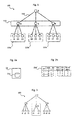
- Figure 1 depicts an embodiment of a streaming tree network 100, which may e.g. be used to distribute a variety of different data streams to a plurality of network nodes.
- the network nodes of the streaming tree network 100 may comprise network-enabled personal computers or any other network elements with a suitable network interface that enables to establish logical links 150 to further network elements.
- the network nodes of the streaming tree network 100 are arranged in a logical tree-like topology which comprises a plurality of levels.
- Reference sign 3 depicts a network node that represents the root level of the tree topology.
- Network nodes 4, 6, 8, which are child nodes to the root node 3, represent an intermediate level of the network 100.
- Node 4 comprises three child nodes 9, 11, 23, whereas node 6 comprises three child nodes 16, 21, 25, and node 8 comprises three child nodes 13, 14, 19. Since the nodes 9, 11, 23, 16, 21, 25, 13, 14, 19 constitute the lowest level of the network 100, they are also denoted as "leaf nodes".
- Nodes 9, 11, 23 having the same parent node 4 are also denoted as sibling nodes or simply siblings, whereas siblings 6, 8 of a node's parent node 4 are also referred to as aunt and/or uncle nodes or simply aunts and/or uncles.
- the logical tree-like topology of network 100 may e.g. be established independent of an actual underlying physical network infrastructure such as the Internet, a local or wide area network (LAN, WAN) or even a wireless LAN (WLAN) or any other network infrastructure enabling the nodes 3, 4, 6, 8, .. to communicate with each other.
- LAN local or wide area network
- WLAN wireless LAN
- Streaming trees such as defined by network 100 usually suffer from the disadvantage that child nodes 16, 21, 25 are losing their connection to the remaining network nodes if an upper level node such as the parent node 6 fails or explicitly leaves the tree topology 100. In these cases data streaming to the respective child nodes 16, 21, 25 is interrupted which is highly undesirable.
- a network node 21 is configured to maintain local backup information on at least one potential backup node 16 that is capable of replacing the parent node 6 of said network node 21.
- the provisioning of the local backup information within the network node 21 advantageously enables to promptly react to link failures and avoids lengthy signaling procedures as known from prior art systems.
- FIG. 2a schematically depicts a simplified block diagram of a network node 21 according to one embodiment.
- Node 21 comprises local backup information 21a which may e.g. be stored to local memory means comprised within said node 21.
- said local backup information 21a may be comprised in a local database of said node 21 or in a simple list or table or some other form suitable for prompt access in the case of a link failure.
- said local backup information 21a comprises information on one or more network nodes 16, 21, 25 having the same parent node 6 as the network node 21. This is particularly advantageous, since it enables the network node 21 to efficiently select one of its siblings 16, 25 as a backup node. It is also possible that said backup information 21a comprises information on the suitability of the node 21 itself as a backup node. In this case, too, an efficient establishment of a backup structure within the affected tree portions is possible since no signaling with further nodes 4, 8 is required to again supply the affected child nodes 16, 21, 25 of the failing parent node 6 with streaming data. In this case, the node 21 itself will replace its failed parent node 6.
- all child nodes 16, 21, 25 of a parent node 6 comprise the functionality of the above explained embodiment, i.e. locally provide backup information 21a.
- these child nodes 16, 21, 25, or siblings, as seen from their own network level constitute a specific group 120b of nodes which is also referred to as "pre-failure-network", since these nodes 16, 21, 25 will collaboratively build a backup-sub-tree of the network structure if their parent node fails by using the locally provided backup information.
- the nodes 9, 11, 23 may constitute a further pre-failure-network 120a
- the nodes 13, 14, 19 may constitute a further pre-failure-network 120c
- the intermediate nodes 4, 6, 8 may also constitute a further pre-failure-network 110 in the sense of the present embodiment.
- the nodes of the network 100 are enabled to efficiently rebuild the tree topology in order to supply each node with streaming data.
- said local backup information 21a comprises information on one or more sibling network nodes 4, 8 of said parent node 6, i.e. the network node 21 locally maintains backup information 21a on its own aunt and uncle nodes as potential backup parent nodes.
- node 21 may use its own siblings 16, 25 and/or the siblings 4, 8 of its parent node 6 for backup purposes.
- said local backup information 21a ( Figure 2a ) comprised within node 21 comprises information on which of said plurality of network nodes 16, 21, 25 is configured to operate as a potential backup node and/or a fan-out and/or a number of free slots and/or a sort key of the respective node 16, 21, 25.
- a node's fan-out value is usually provided by the respective node itself and describes how many child nodes it may take to be filled up to capacity.
- the amount of free slots indicates how many child node positions are left at a specific node until its fan-out is reached.
- the sort key may advantageously be used to sort various sibling nodes 16, 21, 25 depending on their suitability as a backup node and/or their communications capabilities.
- a very efficient way of arranging said backup information 21a within a node 21 is a load table, an example of which is depicted by Figure 2b .
- the load table 21a' which may e.g. be used to organize the backup information 21a ( Figure 2a ) that is locally stored within said node 21, may e.g. comprise one row per node. I.e., since the currently discussed pre-failure-network 120b comprises a total of three sibling nodes 16, 21, 25, the load table 21a' comprises three rows for the three nodes 16, 21, 25.
- the title row of table 21a' which comprises column titles, of course, only serves illustrative purposes.
- the load table 21a' has a plurality of columns comprising
- the load table 21a' enables an efficient browsing and sorting of the sibling nodes 16, 21, 25.
- each node 16, 21, 25 of the pre-failure network 120b manages backup information concerning the pre-failure network 120b, preferably in the tabular structure as explained above with reference to Figure 2b .
- each node 16, 21, 25 of the pre-failure network 120b may locally store an instance of the same load table 21a'.
- the load table 21a' contains a table row for each node 16, 21, 25 that is part of the pre-failure network 120b and stores additional information (fan-out, free slots, backup parent) describing the node's capacity.
- All nodes 16, 21, 25 from the same pre-failure network 120b are preferably required to always hold completely identical load tables 21a' to be sure they work on the same basis in the case of a network failure that affects streaming operation to them, i.e. due to a failure of parent node 6.
- each member of the respective pre-failure networks 110, 120a, 120b, 120c comprises a local load table 21a', which is identical to the load tables of its siblings that define the further members of the respective pre-failure networks 110, 120a, 120b, 120c.
- the affected nodes can efficiently rebuild the tree topology, i.e. fully establish backup sub-trees and the like.
- the sort-key information may be used to sort the members 16, 21, 25 in a specific order according to their suitability as a backup node.
- the sort key value may e.g. be determined by multiplication of the "fan-out" value and the "free slots" value and may be used as a primary indicator for table sorting of the load table 21a'. High values of fan-out and free slots qualify a node to be placed in an upper layer of a potential backup sub-tree, because such a node can support a corresponding number of child nodes. Therefore, the table 21a' is preferably sorted in descending order by the sort key.
- the node id is used as a secondary sorting criterion, i.e. in an ascending order.
- the table column "backup parent" describes the row number that will be the parent node in the backup sub-tree.
- the nodes 16, 21 and 25 constitute a pre-failure network 120b.
- Each of the nodes 16, 21, 25 preferably has exactly the same load table 21a' as depicted by Figure 2b .
- a fan-out value of three is asserted for each node 16, 21, 25.
- the values in column "backup parent" describe the row numbers from the node table, which contain the certain parent node, i.e. that node of the pre-failure network 120b that represents a potential backup node.
- a backup parent value of "0" identifies node 16 to be the root of the backup sub-tree, i.e. the potential backup parent for the case of failure of the current parent node 6.
- the potential backup node 16 is configured to contact its grandparent node 3 for temporary stream recovery as the only one. I.e. the further nodes 21, 25 of the pre-failure network 120b do not contact the grandparent node 3 since from their respective backup parent values of "1" they can determine that they are no potential backup parent nodes.
- node 25 looks up its backup parent value in its load table. It finds the value "1”, which invokes it to search for table row number 1 that contains its planned backup parent node 16. In row 1, node 25 finds the id of node 16, which will thus be considered as its backup parent in case of temporary recovery becoming necessary. Likewise, node 21 looks up its backup parent value in its load table. It finds the value "1”, which invokes it to search for table row number 1 that contains its planned backup parent node 16. In row 1, node 25 also finds the id of node 16, which will thus be considered as its backup parent in case of temporary recovery becoming necessary.
- the nodes 21, 25 can determine their planned backup parent node in the case of a link failure. Moreover, from analyzing its own local load table 21a', the nodes 16 can determine that it is determined to be the backup parent node for its siblings 21, 25 in the case of a link failure.
- a new sub-tree structure for the pre-failure network 120b is established according to the backup information 21a comprised in the load tables 21a' of the member nodes 16, 21, 25 if their parent node 6 fails.
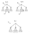
- the whole streaming tree network assumes the topology as depicted by Figure 3 .
- Node 16 is the root of the backup sub-tree and therefore replaced its former parent node 6.
- Nodes 21 and 25 got bound to node 16 as child nodes, as defined by the load table 21a'.
- FIG. 3 shows the nodes 4 and 8 resting at their original positions, cf. Figure 1 , and keeping their child nodes.
- the network branches associated with nodes 4, 8 remain completely unaffected when node 6 fails.
- the network nodes 16, 21, 25 apart from locally maintaining backup information 21a ( Figure 2a ), preferably in form of a load table 21a' ( Figure 2b ), the network nodes 16, 21, 25 have to take different roles and have certain areas of responsibility to ensure a successful organization of a pre-failure network 120b and failure response.
- the network nodes are configured to signal e.g. a change of said local backup information 21a to at least one further node.
- each message is preferably sent by one node and received by a single target node, which both can be either a parent node or a child node.
- a node preferably cannot send a message to itself.
- every message may contain information (e.g., alteration or deletion) about a certain node and may also identify the pre-failure network 120b this node is part of.
- a minimal number of required parameters are the id of the certain node and the id of its parent node to identify the pre-failure network 120b.
- the following three messages are used to communicate changes of pre-failure networks 120b.
- the RecoveryUpdateMessage is employed to communicate changes of existing nodes or to introduce new nodes to the pre-failure network 120b.
- a recipient node of the RecoveryUpdateMessage has to update the node with the delivered id to its local load table, or add it if it does not already exist.
- the first parameter ID1 of the RecoveryUpdateMessage is the id of the node, which is parent of the affected pre-failure network, e.g. node 6 for the pre-failure network 120b.
- the second parameter ID2 of the RecoveryUpdateMessage identifies the node which has experienced a change.
- a RecoveryRemoveMessage tells a recipient node to remove the node with the delivered node id "ID1" from its load table 21a'.
- ID1 denotes the node which has to be deleted from the recipient node's pre-failure network, e.g. from the list representing the backup information 21a or the load table 21a', respectively.
- the RecoveryGrandparentMessage tells a recipient node the contact address of its grandparent node, which is required for replacement of the parent node in case of failure.
- the single parameter ID1 identifies the grandparent node.
- Figure 4a, 4b depict a further embodiment of the invention which comprises a node join procedure in the context of the streaming tree network of Figure 1 by using the above explained messages.
- a new node 30 joins the pre-failure network 120b.
- the presently discussed pre-failure network 120b is framed by a dashed rectangle in Figures 4a, 4b . It initially comprises the nodes 16, 21, and 25. A new node 30 has just joined the parent node 6 as a child and now has to take part in pre-failure calculations, i.e. information on the newly joined node 30 has to be added to the backup information 21a according to the inventive embodiments in order to enable node 30 to actively take part in the backup and tree restore mechanisms explained above.
- Node 6 is the parent node of nodes 16, 21, 25, and 30 and therefore also is the parent node of the whole pre-failure network 120b, while node 3 is the grandparent node of nodes 16, 21, 25, and 30, and the parent node of node 6.
- table 1 represents a load table of node 4 as maintained prior to the joining of node 30: (table 1) row node ID fan-out free slots sort key backup parent 1 4 5 2 10 0 2 6 5 2 10 1 3 8 5 2 10 1
- nodes 4, 6 and 8 are capable of taking 5 child nodes each (fan-out), while each of their children 16, 21, and 25 can deliver 3 child nodes in this example, cf. table 2 below, which represents a load table of node 16 as maintained prior to the joining of node 30: (table 2) row node ID fan-out free slots sort key backup parent 1 16 3 3 9 0 2 21 3 3 9 1 3 25 3 3 9 1
- the load tables of a specific pre-failure network's nodes are preferably always congruent, which is e.g. ensured by mutual synchronization, cf. the explanations with reference to Figure 6b below.
- node 30 After node 30 has finished its joining procedure at the streaming tree network 100, it is bound to node 6 as the child in a parent-child relationship.
- the joining itself may e.g. be performed by per se known signalling mechanisms suitable for application within streaming tree networks 100.
- node 6 initiates a process of load table maintenance of its child nodes 16, 21, 25, 30 to ensure that the backup information 21a according to the inventive embodiments is up to date, i.e. particularly reflects the altered structure of the pre-failure network 120b having a new sibling node 30.
- parent node 6 needs to inform child nodes 16, 21, and 25 about their new sibling 30.
- parent node 6 has to notify node 30 that the nodes 16, 21, and 25 are part of its pre-failure network 120b so that the new node 30 can update its load table accordingly.
- node 30 needs to be notified about the identity of its grandparent node 3.
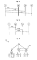
- Figure 6a depicts the message flow employed according to a preferred embodiment so as to accomplish the steps of signalling involved in the above explained process of load table maintenance.
- parent node 6 issues a RecoveryUpdateMessage m1 with the parameters (6,30) to its child node 16 to notify the child node 16 about a new sibling or member node of the pre-failure network 120b.
- the first parameter of the RecoveryUpdateMessage m1 defines the current parent node 6, and the second parameter of the RecoveryUpdateMessage m1 identifies the new node 30.
- Parent node 6 also informs the further child nodes 21, 25 accordingly by transmitting respective messages m1(6,30) to the nodes 21, 25.
- parent node 6 After that, parent node 6 notifies new node 30 on its "new" siblings 16, 21, 25, which is also accomplished by forwarding a total of three messages m1 of the RecoveryUpdateMessage type to new node 30: m1(6,16), m1(6,21), m1(6,25).
- the messages m1, m2 explained above with reference to the communications diagram of Figure 6a are used to create a load table at node 30 and to extend the load tables of nodes 16, 21 and 25 by information related to node 30.
- the load tables of nodes 16, 21, 25 and 30 are congruent, i.e. all members or sibling nodes 16, 21, 25, 30 of the pre-failure network 120b ( Figure 4b ) have identical load tables and can thus efficiently reorganize themselves in case of failure of their parent node 6.
- Table 3 The contents of the load tables of nodes 16, 21, 25 and 30 after the procedure according to Figure 6a are depicted by table 3 below: (table 3). row node ID fan-out free slots sort key backup parent 1 16 3 3 9 0 2 21 3 3 9 1 3 25 3 3 9 1 4 30 3 3 9 1
- Figure 4b depicts the resulting tree structure after a successful joining process of node 30 as a child node to parent node 6.
- the load tables of its siblings and its parent need to be updated as well.
- node 30 parts from the streaming tree, Figure 5 the load tables of nodes 4, 6, 8 and 16, 21, 25 have to be updated.
- parent node 6 of node 30 Since only the parent node 6 of node 30 detects the parting or the absence of node 30, the parent node 6 has to inform the other member nodes 16, 21, 25 of the affected pre-failure network 120b. To accomplish this, parent node 6 notifies the other member nodes 16, 21, 25 by means of respective RecoveryRemoveMessage notifications, cf. the messages m3(30) of Figure 6c . Upon receipt of these messages m3(30), nodes 16, 21, and 25 can update their load tables, which will assume a form as represented by table 2 above.
- node 6 sends an update message to its parent node 3 in order to have its pre-failure siblings 4, 8 be informed by node 3 about the structural change, cf. Figure 6d and the respective RecoveryUpdateMessage notifications m1(3,6). In order to notify nodes 4 and 8 about the change, node 3 passes the update messages m1(3,6) to them.
- positions of nodes of a pre-failure network 120b in a backup sub-tree are calculated by iterating over the load table. This means to create table sections dependant on the preceding sections' capacities. Each table section (respectively backup sub-tree layer) contains a number of nodes equal to the sum of free slots of all nodes from the previous section. This allows creation of the backup sub-tree in regard of special node capacities, such as a very high fan-out of a single node for example.
- Every node of the streaming tree or at least of a specific pre-failure network 120b is configured to run through this procedure for its pre-failure network load table 21a' ( Figure 2a ) completely on its own, preferably every time the contents of the load table 21a' change, i.e. due to a node join or node leave event.
- the algorithm according to the present embodiment requires an ordered load table and two structures to represent several attributes of node sets in order to begin.
- the set structures must be able to store the size of a set, the sum of free slots of a set and the row number of the first node within it.
- a set represents a section of the load table. Firstly, a table row is pulled from the table. If it is the first row at all, this row is set as the root of the backup sub-tree and its attributes are stored in the currentSet variable. From now on, each row is handled the same. If there are free slots in the currentSet variable, the algorithm searches for one of them by calculating a possible parent node from the currentSet. In case this potential parent node has free slots, the row gets it assigned as its backup parent node.
- nextSet The node's attributes are added to those stored in nextSet, because the node may become a parent node for the next tree layer. Otherwise, the algorithm checks further nodes from the currentSet until the free slot is found. In case there are no free slots in the currentSet, a new tree layer is opened up and currentSet and nextSet are swapped. All upcoming table rows now are assigned to the next backup sub-tree layer until it is completely filled.
- positions of nodes of a pre-failure network 120b in a backup sub-tree are given by a load table.
- a load table is set up in sections. Each load table section contains a number of nodes equal to the sum of free slots of all nodes from the previous section.
- the first section in a load table consists of four nodes if the parent peer, i.e. node, has a capacity of four. Hence if these four nodes in the first section each also have a capacity of four, the next section in the load table can consist of 16 nodes.
- This setup of the load table in sections allows creation of the backup sub-tree in regard of special node capacities, such as a very high fan-out of a single node for example.
- a node To get a node's position in the backup sub tree, a node has to iterate about the self-calculated load table to get its new position in the backup tree.
- a given algorithm according the present embodiment requires a pre-ordered load table according to the node's capacities and two virtual structures "currentSet” and "nextSet", cf. above, which represent attributes of nodes in order to begin.
- a node set which consists of a node's characteristics must be able to store the size (node count), the sum of free slots and the row number of the first node within it.
- a node set is mapped into a row of a load table.
- To get a load table which builds up the backup tree in case of a node failure a given algorithm assigns backup parents to each node set in a row.
- the first row of the load table is taken. This row is set as the root of the backup sub-tree and its attributes are stored in a so called 'currentSet' variable. From now on, each row is handled the same. If there are free slots in the currentSet variable, the algorithm searches for one of them by calculating a possible parent node from the currentSet. In case this potential parent node has free slots, the row gets it assigned as its backup parent node. The node's attributes are added to those stored in nextSet, because the node may become a parent node for the next tree layer. Otherwise, the algorithm checks further nodes from the currentSet until the free slot is found. In case there are no free slots in the currentSet, a new tree layer is opened up and currentSet and nextSet are swapped. All upcoming table rows now are assigned to the next backup sub-tree layer until it is completely filled.
- Table 4a shows an ordered load table with the column of backup parents not yet filled.
- the iterative procedure picks the first row from the load table and sets it as the root node of the backup sub-tree.
- the backup parent is set to 0 (cf. table 4b below), which means that it is the backup tree root and has no backup parent from within the load table. (table 4b - The backup tree root) Row Node ID Fan-Out Free Slots Sort Key Backup Parent 1 2 3 3 9 0
- the root node's amount of free slots is 3, as shown in (table 4b.
- the step to proceed is to select the upcoming three rows from the load table in order to fill the second tree layer. All nodes from the second layer have to take the root node as their parent; it is located in the first table row, so their backup parent value is 1.
- (table 4c - Second layer of the backup tree) Row Node ID Fan-Out Free Slots Sort Key Backup Parent 1 2 3 3 9 0 2 3 3 3 9 1 3 4 3 3 9 1 4 5 3 3 9 1
- the second layer contains three nodes located in table rows 2 - 4. They deliver 9 free slots for the third backup tree layer.
- the algorithm has to select the succeeding 9 nodes from the load table in order to assign them to these free slots.
- the slots are preferably filled regarding to homogenous distribution of child nodes over all nodes from the layer above.
- the last three rows from the load table therefore are assigned to different parent nodes as shown in table 4d. (table 4d - Complete calculation of backup) Row Node ID Fan-Out Free Slots Sort Key Backup Parent 1 2 3 3 9 0 2 3 3 3 9 1 3 4 3 3 9 1 4 5 3 3 9 1 5 6 3 3 9 2 6 7 3 3 9 3 7 8 3 3 9 4
- the above explained embodiments enable an immediate, fast, independent and efficient recovery of a tree topology in case of a stream failure.
- a minimum effort regarding peer-to-peer communications i.e. communications between sibling nodes
- peer-to-peer communications is restricted to the members of a pre-failure network 120b.
- the network element is configured to use aunt and/or uncle nodes as backup nodes for the case of failure, in contrast to using its own siblings. Consequently, in this embodiment, the backup information 21a ( Figure 2a ) or a respective load table 21a' ( Figure 2b ) comprises information on aunt and/or uncle nodes that are potential backup nodes. I.e., siblings of a parent node can be used to enable fallback for at least temporary stream recovery in case the parent node fails.
- a pre-failure network can be defined as a collection of all siblings of one single node. Such pre-failure network can be used for temporary stream recovery for the single node's child nodes in case of its failure.
- nodes do not exactly know which node from the pre-failure network will be its backup parent node on failure, but they are configured to determine such backup parent node on their own if it is necessary.
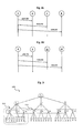
- FIG. 7a An exemplary pre-failure network based on aunt and/or uncle nodes is presented by Figure 7a .
- the three nodes 9, 11, 23 framed by a dotted rectangle all have the same pre-failure network 110a comprising the nodes 6, 8 which are siblings of the parent node 4 of the three nodes 9, 11, 23.
- the parent node 4 itself is not part of the pre-failure network 110a, because it is the one whose failure shall be compensated by the pre-failure network 110a.
- nodes 4, 8 form a respective pre-failure network (not shown) for the nodes 16, 21, and 25, and nodes 4, 6 form a respective pre-failure network (not shown) for the nodes 13, 14, and 19.
- At least one node, but preferably every node 9, 11, 23 comprises locally stored backup information which in the present case represents information about its pre-failure network 110a and the involved potential backup nodes 6, 8 constituting said pre-failure network 110a.
- said backup information is arranged in form of an ordered list of nodes or a table.
- Such list or table may have a form similar to that of the load table 21a' described above with reference to Figure 2b and is thus also referred to as load table for the further explanations, although slight variations regarding the table structure and/or contents may occur.
- the load table according to this embodiment too, represents a form of arranging data related to potential backup nodes 6, 8, as with the further embodiments already explained above.
- the load table comprises all siblings 6, 8 of the parent node 4, i.e. the aunts and uncles of the child nodes 9, 11, 23.
- the child nodes 9, 11, 23 need to be up-to-date about their uncles and uncles 6, 8 at any time.
- the parent node 4 may mirror the pre-failure network related information of its children 9, 11, 23, i.e. their load tables, in order to keep them available for new nodes that join the parent node 4 as a child node. This advantageously reduces the amount of signaling required for adding new child node.
- the dashed rectangle indicates the pre-failure network 110a of the nodes 9, 11, 23 framed by a dotted line.
- the notation of this pre-failure network 110a comprising the nodes 6 and 8 (in the same order) is PN ⁇ 6,8 ⁇ .
- nodes 9, 11, 23 are assigned to their uncles and uncles 6, 8 by means of an autonomous and independent calculation of the respective backup parent which is conducted by each child node 9, 11, 23.
- the child nodes 9, 11, 23 can advantageously determine their backup aunt/uncle node without requiring any communication or signaling with other nodes if they have proper backup information 21a that is locally stored.
- nodes 9, 11, and 23 are not required to know each other, but they all hold the same pre-failure network PN ⁇ 6,8 ⁇ 110a.
- the nodes 9, 11, 23 may use their own ids (9, 11, 23) to each calculate a suitable backup parent e.g. by means of a modulo operation with the overall amount of nodes in the pre-failure network 110a, i.e. presently a value of two, because of the two uncles/aunts 6, 8.
- the result of this operation is a sequence number indicating the position of the backup parent node in PN ⁇ 6,8 ⁇ .
- nodes 9, 11, 23 since none of the nodes 9, 11, 23 has an even id, all of them are assigned to backup node 8, which results in a sub-optimal distribution of child nodes to the available backup nodes 6, 8, because node 6 is not used at all, while node 8 might be overburdened by three new child nodes 9, 11, 23.
- a further improvement regarding assignment of the nodes 9, 11, 23 to a backup node 6, 8 is achievable if the nodes 9, 11, and 23 comprise information on each other. In this case, they are preferably configured to put themselves into an ascending order by their id and each of them calculates its appropriate backup parent ad-hoc.
- the nodes 9, 11, 23 use a modulo-function that alternately assigns them to node 6 or 8. This procedure can lead to an assignment of backup parent nodes as shown in table 5, which can be considered as a form of backup information or load table for the nodes 9, 11, 23. (table 5) node ID node sequence parent sequence backup parent 9 0 0 6 11 1 1 8 23 2 0 6
- nodes 9, 11, and 23 are arranged into a sequence of ascending node ids, cf. the first column of table 5. Their sequence numbers are printed in the second column. Their common pre-failure network is PN ⁇ 6,8 ⁇ 110a and has a size of two elements.
- the node sequence number from column 2 is modulated using the size "2" of the pre-failure network 110a.
- each node 9, 11, 23 assumes substantially two roles at the same time. Firstly, it is a child node of the parent node 4, which means that it is configured to receive information concerning its aunts and uncles 6, 8 (if available) and to store it as pre-failure network 110a, for instance in form of the backup information or a load table, respectively. Secondly, the node is configured to deliver information concerning each child node 9, 11, 23 to the other child nodes 9, 11, 23, because they have to know about their respective siblings. That is, a network node 23 is configured to receive backup information regarding its own aunt and uncle nodes 6, 8.
- a respective parent node 4 is configured to signal information regarding its child nodes to further child nodes.
- a specific network node may comprise both a functionality to receive backup information regarding its own aunt and uncle nodes and a functionality to signal information regarding its child nodes to further child nodes.
- message types proposed that are preferably sent from parent node 4 to a child node 9, 11, 23. According to the present embodiment, it is not required for messages to float up the tree topology, i.e. from a child node to a parent node, which advantageously reduces signaling efforts.
- a first proposed message that can be used for the signaling in the context of the present embodiment is the NodeUpdateMessage(ID1, ID2).
- the NodeUpdateMessage can advantageously be used to introduce a new sibling node 11, 23 or a new aunt/uncle node 6, 8 to a child node 9. Whether the newly introduce node is a sibling or an aunt or uncle is indicated by the first parameter ID1 of the NodeUpdateMessage, that describes the node whose failure the message is related to.
- the second parameter ID2 of the NodeUpdateMessage defines the affected node that shall be updated or added to a certain pre-failure network.
- a second proposed message that can be used for the signaling in the context of the present embodiment is the NodeRemoveMessage(ID1, ID2).
- the NodeRemoveMessage informs a target or recipient node about removal of a certain node.
- the first parameter ID1 describes the node whose failure is affected; the second parameter ID2 defines the certain node to be deleted.
- Figure 7c , 7d depict an embodiment related to a node join procedure in the context of the streaming tree network of Figure 7a .
- the dashed rectangle in Figure 7c indicates the nodes 9, 11, 23 that will be examined in the following description of a communications process that relates to the node join event.
- the common pre-failure network 110a of the nodes 9, 11, 23 consists of nodes 6 and 8, also cf.
- Figure 7a depicts an embodiment related to a node join procedure in the context of the streaming tree network of Figure 7a .
- the dashed rectangle in Figure 7c indicates the nodes 9, 11, 23 that will be examined in the following description of a communications process that relates to the node join event.
- the common pre-failure network 110a of the nodes 9, 11, 23 consists of nodes 6 and 8, also cf.
- Figure 7a .
- node 30 has joined the streaming tree at node 3 and is bound in a parent-child relationship to node 3.
- the initial pre-failure network of nodes 9, 11, and 23 is PN ⁇ 6, 8 ⁇ as explained above.
- Node 4 advantageously also knows about this pre-failure network since node 4 is responsible for its child nodes 9, 11, 23. Now, that node 30 has just joined the tree 100, node 3 initiates maintenance of the pre-failure networks. First of all, the new node 30 is introduced as a sibling to all of the child nodes 4, 6, 8 of node 3.
- node 3 is configured to signal corresponding information to its child nodes 4, 6, 8, which is preferably accomplished by the above explained mechanism using the NodeUpdateMessage, also cf. Figure 8a .
- Node 3 transmits a respective NodeUpdateMessage m4(4,30), m4(6,30), m4(8,30) to all of its child nodes 4, 6, 8 to notify them of their new sibling node 30.
- Nodes 4, 6, and 8 are configured to recognize that this update must affect their respective child nodes, because their own IDs are set as first message parameter of the NodeUpdateMessage issued by node 3. Consequently, each of the nodes 4, 6, 8 takes the following measures that are explained only for the case of node 4 for sake of simplicity. The other nodes 6, 8 follow basically the same procedures.
- Node 4 stores the new node 30 in addition to nodes 6 and 8 as an aunt or uncle node of its children, wherein said aunt or uncle node may also be used as a backup parent node. I.e., the aunt/uncle-based pre-failure network 110a is extended by the new node 30. Node 4 then passes the respective NodeUpdateMessage m4(4,30) downwards the tree topology to its child nodes 9, 11, 23, cf. Figure 8b .
- the first message parameter of message m4(4,30) remains the same, because the recipient nodes 9, 11, 23 must not store node 4 as possible backup parent.
- each of nodes 9, 11, and 23 know their pre-failure network 110a to be PN ⁇ 6, 8, 30 ⁇ , i.e. extended by the newly added node 30.
- node 3 is configured to notify node 30 of its pre-failure network, which would consist of all siblings of node 3. with the present example, there are no siblings to node 3, because node 3 is the root node. In effect, node 30 does not have a pre-failure network according to the aunt/uncle-based principle illustrated with reference to the Figures 7a to 8d .
- node 30 may not benefit from an aunt/uncle-based pre-failure network that may compensate for a failure of root node 3.
- node 30 may very well comprise backup information on its sibling nodes 4, 6, 8 in order to use one of these nodes 4, 6, 8 as a potential backup parent node in case of a failure of root node 3.
- the corresponding embodiments have already been explained with reference to the Figures 1 to 6d . Consequently, a network node may advantageously use its own siblings and/or the siblings of its parent node (i.e. its own aunts and/or uncles) for backup purposes. This principle can be applied to any node of the streaming tree network 100 to ensure maximum resilience and flexibility.
- Figure 7d shows the streaming tree topology after node 30 has completely been integrated into the pre-failure networks.
- the dotted rectangle 110a defines the pre-failure network of nodes 9, 11, and 23: PN ⁇ 6, 8, 30 ⁇ .
- root node 3 is the only one to detect this event, because it is the parent node of node 30.
- Root node 3 is thus preferably configured to send update messages to its child nodes 4, 6, 8 to notify them about the absence of node 30, cf. the NodeRemoveMessage notifications m5(4,30), m5(6,30), m5(8,30) of Figure 8c .
- the recipient nodes 4, 6, 8 are configured to be aware of the fact that these messages m5(4,30), m5(6,30), m5(8,30) affect their respective child nodes, because their own ids 4, 6, 8 are set as the first parameter of the messages m5(4,30), m5(6,30), m5(8,30).
- the nodes 4, 6, 8 are thus configured to pass the respective message m5(4,30) to the child nodes 9, 11, 23, .., cf. Figure 8d .
- Nodes 9, 11, and 23 are configured to detect the messages to affect their own pre-failure network 110a and therefore remove node 30.
- their pre-failure network 110a is PN ⁇ 6, 8 ⁇ again, cf. Figure 7a .
- a network node 2 is configured to maintain local backup information 21a on at least one potential backup node that is capable of replacing a parent node 5 of a further network node 7 in case of failure of said parent node 5, cf.
- Figure 5 which shows a further streaming tree network 101.
- This embodiment of the invention is also denoted as delegation approach, because it proposes to select a specific node 2 to act as delegator node that is configured to receive a request of a further node 7 for a potential backup node, and to forward information regarding said potential backup node to said further node 7.
- a pre-failure network consists of the whole sub-tree 111 of which the delegator node 2 is the root node, cf. Figure 9 .
- the delegator network node 2 is configured to determine a capacity value that defines a node's suitability as a potential backup parent for at least one network node comprised within the sub-tree 111 associated with said delegator network node 2.
- the delegator network node 2 is configured to determine said capacity value depending on a number of active child nodes of a respective node, a fan-out of said respective node, and a number of backup children that are already registered for said respective node. This embodiment enables to precisely assess a node's suitability as a backup node.
- said delegator network node 2 is configured to sort a plurality of nodes of said sub-tree 111 according to said capacity value, and to forward information on a potential backup node having the highest capacity value to said further node 7.
- a backup depth may be defined which is a value that describes a count of layers a delegator node 2 may select backup parents from.
- the backup depth describes a layer distance to each node's delegator (as seen upwards the tree).
- Nodes that contact the delegator node 2 for a backup parent may e.g. be located one layer below this backup depth.
- a node is configured to contact its designated delegator node 2 and to request a backup parent to receive streaming data from upon detecting its parent's failure.
- Information on the identity and/or further parameters of the delegator node 2 is preferably locally stored to the respective node, e.g. in the form of backup information 21a in analogy to the network node 21 explained with reference to Figure 2a .
- the local storage of the delegator node 2 enables an efficient response to parent node failures and thus minimizes the time no streaming data can be received by the node.
- the delegator node 2 is preferably configured to comprise knowledge about its sub-tree 111 up to the predetermined backup depth, which particularly constitutes a form of pre-failure network the delegator node 2 maintains. Based on its knowledge of the pre-failure network, the delegator node 2 is able to return a proper backup node to a requesting node.
- Figure 9 shows two examples of delegator nodes each being assigned a backup depth of 2.
- Node 0, which is marked by a dashed circle, is configured to operate as a delegator node for all nodes 5, 27, 31, 4, 6, 8, 15, 17, 30 within the dashed rectangle 112.
- Node 2, which is marked by a dotted circle, is configured to operate as a delegator node for all nodes that are located 2 layers below it. These nodes 7, 10, 20, 33, 34, 38, 35, 36 are framed by a dotted rectangle.
- any node 0, 2 configured as a delegator node is required to comprise knowledge about its sub-tree 111 down to the backup depth.
- the delegator node 0, 2 is not necessarily required to know which of its descendant nodes is a parent or a child of another node.
- the delegator node 0, 2 is rather only configured to hold a list of nodes which is preferably ordered ascending by a capacity value which is calculated as described below. Said list represents a form of backup information 21a that is to be locally stored to the delegator nodes 0, 2.
- the capacity value may also be denoted as "backup node capability" and is a parameter that indicates a nodes' capability of taking the role of another node's backup link or backup parent, respectively.
- the capacity value is a positive number which enables an efficient retrieval of suitable backup nodes by the delegator nodes 0, 2 by means of comparison of their capacity values.
- Every node of the network 101 may be characterized by three properties that are useful for the calculation of a meaningful capacity value:
- the fan-out value f of an exemplary node 121 depicted by Figure 10 a) corresponds to the total number of lines that are aligned top-down in Figure 10 a) , which indicate a theoretical number of possible child nodes supported by the node 121, no matter if dashed or solid lines.
- the fan-out value equals 4. This also applies to the further settings according to Figures 10 b) and 10 c) .
- Registered backup children are located in the dashed cloud 122 of Figure 10 a) .
- the parent node 122 of Figure 10 a has two active child nodes and two backup children. Combined with the fan-out of 4, the equation (1) according to the present embodiment results in 1, which indicates the node 122 being exactly filled.
- a capacity value above 1 shows that the node might be overstrained in case of one or more failures, as in case of Figure 10 b) .
- a delegation node 0, 2 After a delegation node 0, 2 calculated the capacity values of each peer node in its sub tree 111, it preferably sorts the list according to the capacity value. Thus, the delegator node 0, 2 can quickly determine a suitable backup parent node for a requesting node. When a node requests a backup parent, its delegator node 0, 2 e.g. picks the first node from its sorted list and returns it as backup parent. Afterwards, the delegator node eventually reorders the list, because changes have occurred.
- each node of the network 101 is configured to be capable of acting as a delegator node. As explained above, that means to assign other nodes from a lower level to backup parents from the pre-failure network 111.
- the delegator node 0, 2 may also assign itself to a requesting node as a backup parent.
- the following messages are proposed for signaling purposes.
- all messages only flow upwards the tree topology 101, if not specified differently.
- the SubtreeUpdateMessage is used to inform upper tree layers about a new or an altered node.
- the "Sequence” parameter is a list of nodes and their respective capacity values. The list may comprise information on one or more nodes. Using this parameter structure, every recipient node can determine which node is affected and which other nodes have passed the message upwards. A changed or newly added node is preferably the first in the sequence of nodes.
- the second parameter "BackupDepth" defines how many tree layers need to be informed about the update.
- the SubtreeDeleteMessage is used to propagate the absence of a single node to upper tree layers.
- the "Sequence” parameter contains a list of one or more nodes.
- "BackupDepth” describes the desired amount of layers the message needs to travel.
- This message is used to send a request upwards the tree topology in order to find the delegator node 0, 2.
- the "ID” parameter contains the originator's id; the "BackupDepth” parameter defines how many layers this message shall travel upwards.
- the RespondDelegationNode message is a message that may be sent downwards the tree topology. It originates at the found delegator node 0, 2 and is sent to the node that started the RequestDelegationNode message with its own id.
- This message is used whenever a node has detected its parent's failure and contacts the appropriate delegator node 0, 2 in order to retrieve a backup parent for stream recovery.
- the AssignBackup message tells the recipient node which node to contact for a stream recovery, i.e. the proposed backup parent. It is sent directly from the delegator node 0, 2 to the originator of the RequestBackup message.
- the backup depth is assumed to equal 2.
- Each node's maximum fan-out value is defined to equal 3.
- node 40 has joined the tree topology 101 and is bound in a parent-child relationship to node 2.
- the capacity value C of node 2 has altered and needs to be propagated upwards so that the respective delegator node's backup information can be kept up-to-date.
- the new node 40 has to gather information on its delegator node.
- node 40 starts requesting its delegator node using the global backup depth of 2. For this purpose, node 40 sends a RequestDelegationNode(40, 2) message to node 2.
- Node 2 in its function as the message recipient, evaluates for the "BackupDepth" value. Because it is larger than 1, presently "2", node 2 decrements the "BackupDepth” by a value of 1 and passes the message further upwards to node 0, i.e. a RequestDelegationNode(40, 1) is sent from node 2 to node 0.
- the RequestDelegationNode(40, 1) reaches node 0, the depth value being 1.
- node 0 concludes that it is the delegator node of node 40 and correspondingly notifies node 40 by sending a RespondDelegationNode message with the parameter "0" to node 40: RespondDelegationNode(0).
- node 40 For node 40, the pre-failure phase has finished at this point, because it is now informed on its delegator node 0, which may be contacted in case of a failure of its parent node 2. And yet, the upper tree layers are still uninformed about the change; hence node 40 initiates a tree update by sending a SubtreeUpdateMessage ( ⁇ (40,0) ⁇ , 2) to its parent node 2.
- the exemplary inserted sequence ⁇ (40,0) ⁇ which is the first parameter of the SubtreeUpdateMessage, includes all nodes and their appropriate capacity values, the message has travelled.
- Node 2 receives the SubtreeUpdateMessage and updates its sub-tree information: It adds node 40. It then checks the depth value ("BackupDepth" parameter, cf. the message definitions above), which is "2" in this case. Thus, node 2 concludes that the message has not reached its target depth yet, so node 2 passes the message upwards to node 0 after having added itself to the node sequence. Additionally, node 2 decrements the depth value from "2" to "1": SubtreeUpdateMessage ( ⁇ (40,0), (2,0.75) ⁇ , 1).
- node 0 As can be seen from the SubtreeUpdateMessage, the capacity value of node 2 has been entered as 0.75 using a maximum fan-out of 3. When this message reaches node 0, node 0 evaluates the backup depth value which presently equals "1". Hence, node 0 updates its information of all nodes from within the sequence which are part of its sub-tree (regarding the defined backup depth). In this case, node 0 only needs to update node 2. Now, its sub-tree information is up-to-date and thus node 0 can operate as delegator node based on proper sub-tree information.
- Node 40 knows about its pre-failure node, and the sub-tree information of node 0 is completely up-to-date.
- node 40 In case node 40 detects a failure of its parent node 2, according to one embodiment, it sends a backup request to its delegator node 0: RequestBackup(40).
- delegator node 0 is configured to pick the potential backup node best suited to act as backup parent for node 40 from its backup information, i.e. the information on its sub-tree with associated capacity values, and to returns it to the originator, i.e. the requesting node 40: AssignBackup(3).
- a node's leaving is handled in basically the same way as the above explained joining is performed.
- the former parent of the leaving node preferably initiates a SubtreeDeleteMessage, which flows up the tree topology.
- node 40 is to leave the tree topology
- node 2 only needs to remove node 40 from its children. Additionally, the former parent node 2 needs to inform the former delegator node 0 of the lost node 40, which is accomplished by transmitting a SubtreeUpdateMessage( ⁇ (40,0), (2,1) ⁇ , 1) from node 2 to node 0.
Landscapes
- Engineering & Computer Science (AREA)
- Computer Networks & Wireless Communication (AREA)
- Signal Processing (AREA)
- Data Exchanges In Wide-Area Networks (AREA)
Abstract
Description
- The invention relates to a network node for a streaming tree network and a method of operating a network node for a streaming tree network.
- Streaming tree networks comprise a plurality of network nodes that are arranged in a logical tree-like topology which comprises a plurality of levels. The logical tree-like topology may e.g. be established independent of an actual underlying physical network infrastructure such as the Internet. A plurality of different data streams may be distributed by means of such streaming tree networks to a plurality of consumers.
- Streaming trees suffer from the disadvantage that child nodes are losing their connection to the remaining network, if an upper level node such as a parent node fails or explicitly leaves the tree.
- Hence there is a need for timely recovering tree connectivity, because a large subsection of the tree network may be affected by a link failure. It is desirable to minimize stream interruption time.
- According to an embodiment of the present invention, this object is achieved by a network node for a streaming tree which is configured to maintain local backup information on at least one potential backup node that is capable of replacing a parent node of said network node and/or a parent node of a further network node in case of failure of said parent node. The provisioning of the local backup information advantageously enables to promptly react to link failures and avoids lengthy signaling procedures.
- According to an advantageous embodiment, said local backup information comprises information on one or more network nodes having the same parent node as the network node which enables the network node to efficiently select one of its siblings as a backup node.
- According to a further embodiment, said local backup information comprises information on one or more sibling network nodes of said parent node, i.e. the network node locally maintains backup information on its own aunt and uncle nodes as potential backup parent nodes.
- According to the aforedescribed embodiments, the network node may thus use its own siblings and/or the siblings of its parent node for backup purposes.
- According to a further embodiment, said local backup information comprises information on which of said plurality of network nodes is configured to operate as a potential backup node and/or a fan-out and/or a number of free slots and/or a sort key of the respective node.
- A node's fan-out value is usually provided by the respective node itself and describes how many child nodes it may take to be filled up to capacity. The amount of free slots indicates how many child node positions are left at a specific node until its fan-out is reached. The sort key may advantageously be used to sort various sibling nodes depending on their suitability as a backup node and/or their communications capabilities.
- According to a further embodiment, said backup information is arranged in a load table which comprises one row per node and a plurality of columns comprising a node ID, information on whether a respective node of said plurality of network nodes is configured to operate as a potential backup node and/or a fan-out and/or a number of free slots and/or a sort key. The load table enables an efficient browsing and sorting of the sibling nodes.
- According to a further embodiment, the network node is configured to signal a change of said local backup information to at least one further node. According to a preferred variant, messages comprising the relevant information can be exchanged between nodes to effect said signalling.
- According to a further embodiment, said network node is configured to determine a potential backup node out of said one or more sibling network nodes of its parent node depending on its own node ID and/or on at least one of its own sibling nodes. The evaluation of its own ID enables the network node to determine a potential backup node without any knowledge on its own sibling nodes and thus requires no signalling for the determination. On the other hand, when determining the potential backup node depending on at least one of its own sibling nodes, the network node may advantageously synchronize itself with its siblings regarding the usage of the potential backup nodes thus enabling to fairly share the load on the potential backup nodes.
- According to a further embodiment, said network node is configured to sort the network node and its siblings in an ascending or descending order of their node ID to obtain a numbered sequence of nodes, and to assign backup parent nodes to the nodes of said sequence depending on a sequence number of the specific node and on an overall number of backup parent nodes.
- According to a further embodiment, said network node is configured to receive backup information regarding its own aunt and uncle nodes and/or to signal information regarding its child nodes to further child nodes.
- According to a further embodiment, said network node is configured to receive a request of a further node for a potential backup node, and to forward information regarding said potential backup node to said further node.
- According to a further embodiment, said network node is configured to determine a capacity value that defines a node's suitability as a potential backup parent for at least one network node comprised within a sub-tree associated with said network node. According to a further preferred embodiment, said network node is configured to determine said capacity value depending on a number of active child nodes of a respective node, a fan-out of said respective node, and a number of backup children that are already registered for said respective node.
- According to a further embodiment, said network node is configured to sort a plurality of nodes of said sub-tree according to said capacity value, and to forward information on a potential backup node having the highest capacity value to said further node which ensures an efficient assignment of backup nodes depending on the respective capabilities.
- A further solution to the object of the present invention is given by a method of operating a network node for a streaming tree network, wherein said node maintains local backup information on at least one potential backup node that is capable of replacing a parent node of said network node and/or a parent node of a further network node in case of failure of said parent node.
- Further advantageous embodiments are given by the dependent claims.
- Further aspects, features and embodiments of the present invention are given in the following detailed description with reference to the drawings, in which:
- Figure 1
- depicts an embodiment of a streaming tree network,
- Figure 2a
- depicts a simplified block diagram of a network node according to one embodiment of the invention,
- Figure 2b
- depicts a load table as used by the network node of
Figure 2a , - Figure 3
- depicts the streaming tree network of
Figure 1 after establishment of a backup node, - Figure 4a, 4b
- depict a node join procedure in the context of the streaming tree network of
Figure 1 , - Figure 5
- depicts the streaming tree network of
Figure 4b after a node leave event, - Figure 6a, 6b
- depict communications flows in the course of the node join procedure according to
Figure 4a, 4b , - Figure 6c, 6d
- depict communications flows in the course of the node leave procedure according to
Figure 5 , - Figure 7a
- depicts a further embodiment of a streaming tree network,
- Figure 7b
- depicts the streaming tree network of
Figure 7a after establishment of backup nodes, - Figure 7c, 7d
- depict a node join procedure in the context of the streaming tree network of
Figure 7a - Figure 8a, 8b
- depict communications flows in the course of the node join procedure according to
Figure 7c ,7d , - Figure 8c, 8d
- depict communications flows in the course of a node leave procedure,
- Figure 9
- depicts a further embodiment of a streaming tree network,
- Figure 10a, 10b, 10d
- depict different node constellations according to a further embodiment, and
- Figure 11
- depicts a node join procedure in the context of the streaming tree network according to
Figure 9 . -
Figure 1 depicts an embodiment of astreaming tree network 100, which may e.g. be used to distribute a variety of different data streams to a plurality of network nodes. For instance, the network nodes of the streamingtree network 100 may comprise network-enabled personal computers or any other network elements with a suitable network interface that enables to establishlogical links 150 to further network elements. - The network nodes of the streaming
tree network 100 are arranged in a logical tree-like topology which comprises a plurality of levels.Reference sign 3 depicts a network node that represents the root level of the tree topology.Network nodes root node 3, represent an intermediate level of thenetwork 100.Node 4 comprises threechild nodes node 6 comprises threechild nodes node 8 comprises threechild nodes nodes network 100, they are also denoted as "leaf nodes". -
Nodes same parent node 4 are also denoted as sibling nodes or simply siblings, whereassiblings parent node 4 are also referred to as aunt and/or uncle nodes or simply aunts and/or uncles. - As is per se known, the logical tree-like topology of
network 100 may e.g. be established independent of an actual underlying physical network infrastructure such as the Internet, a local or wide area network (LAN, WAN) or even a wireless LAN (WLAN) or any other network infrastructure enabling thenodes - Streaming trees such as defined by
network 100 usually suffer from the disadvantage thatchild nodes parent node 6 fails or explicitly leaves thetree topology 100. In these cases data streaming to therespective child nodes - In order to promptly recover the tree connectivity in such cases, which enables to supply the affected
nodes network node 21 according to an embodiment of the present invention is configured to maintain local backup information on at least onepotential backup node 16 that is capable of replacing theparent node 6 of saidnetwork node 21. - The provisioning of the local backup information within the
network node 21 advantageously enables to promptly react to link failures and avoids lengthy signaling procedures as known from prior art systems. -
Figure 2a schematically depicts a simplified block diagram of anetwork node 21 according to one embodiment.Node 21 comprises localbackup information 21a which may e.g. be stored to local memory means comprised within saidnode 21. For instance, saidlocal backup information 21a may be comprised in a local database of saidnode 21 or in a simple list or table or some other form suitable for prompt access in the case of a link failure. - According to a preferred embodiment, said
local backup information 21a comprises information on one ormore network nodes same parent node 6 as thenetwork node 21. This is particularly advantageous, since it enables thenetwork node 21 to efficiently select one of itssiblings backup information 21a comprises information on the suitability of thenode 21 itself as a backup node. In this case, too, an efficient establishment of a backup structure within the affected tree portions is possible since no signaling withfurther nodes child nodes parent node 6 with streaming data. In this case, thenode 21 itself will replace its failedparent node 6. - It is further preferred that all
child nodes parent node 6 comprise the functionality of the above explained embodiment, i.e. locally providebackup information 21a. In this case, thesechild nodes specific group 120b of nodes which is also referred to as "pre-failure-network", since thesenodes - Likewise, the
nodes network 120a, thenodes network 120c. Of course, theintermediate nodes network 110 in the sense of the present embodiment. - I.e., by means of the locally stored
backup information 21a (Fig. 2a ), the nodes of thenetwork 100 are enabled to efficiently rebuild the tree topology in order to supply each node with streaming data. - According to a further embodiment, said
local backup information 21a comprises information on one or moresibling network nodes parent node 6, i.e. thenetwork node 21 locally maintainsbackup information 21a on its own aunt and uncle nodes as potential backup parent nodes. Thus,node 21 may use itsown siblings siblings parent node 6 for backup purposes. - The further explanations with reference to
Figures 2b to 6d primarily contemplate using the node'ssiblings Figures 7a to 8d . - According to a further embodiment, said
local backup information 21a (Figure 2a ) comprised withinnode 21 comprises information on which of said plurality ofnetwork nodes respective node - A node's fan-out value is usually provided by the respective node itself and describes how many child nodes it may take to be filled up to capacity. The amount of free slots indicates how many child node positions are left at a specific node until its fan-out is reached. The sort key may advantageously be used to sort
various sibling nodes - According to a further embodiment, a very efficient way of arranging said
backup information 21a within anode 21 is a load table, an example of which is depicted byFigure 2b . - The load table 21a', which may e.g. be used to organize the
backup information 21a (Figure 2a ) that is locally stored within saidnode 21, may e.g. comprise one row per node. I.e., since the currently discussed pre-failure-network 120b comprises a total of threesibling nodes nodes - As can be seen from
Figure 2b , the load table 21a' has a plurality of columns comprising - a node ID, which in the present example corresponds to the respective reference signs used to denote specific nodes,
- information on whether a respective node of said plurality of network nodes is configured to operate as a potential backup node (column "backup parent"),
- a fan-out value,
- a number of free slots, and
- a sort key.
- The load table 21a' enables an efficient browsing and sorting of the
sibling nodes - According to a preferred embodiment, each
node pre-failure network 120b manages backup information concerning thepre-failure network 120b, preferably in the tabular structure as explained above with reference toFigure 2b . For instance, eachnode pre-failure network 120b may locally store an instance of the same load table 21a'. As already explained, the load table 21a' contains a table row for eachnode pre-failure network 120b and stores additional information (fan-out, free slots, backup parent) describing the node's capacity. Allnodes pre-failure network 120b are preferably required to always hold completely identical load tables 21a' to be sure they work on the same basis in the case of a network failure that affects streaming operation to them, i.e. due to a failure ofparent node 6. - Preferably, each member of the respective
pre-failure networks pre-failure networks whole network 100, the affected nodes can efficiently rebuild the tree topology, i.e. fully establish backup sub-trees and the like. - According to a further embodiment, the sort-key information may be used to sort the
members - As already mentioned above, the
nodes pre-failure network 120b. Each of thenodes Figure 2b . For the present example, a fan-out value of three is asserted for eachnode pre-failure network 120b that represents a potential backup node. Presently, a backup parent value of "0" identifiesnode 16 to be the root of the backup sub-tree, i.e. the potential backup parent for the case of failure of thecurrent parent node 6. - According to a further embodiment, the
potential backup node 16 is configured to contact itsgrandparent node 3 for temporary stream recovery as the only one. I.e. thefurther nodes pre-failure network 120b do not contact thegrandparent node 3 since from their respective backup parent values of "1" they can determine that they are no potential backup parent nodes. - Exemplary in reference to the load table 21a',
node 25 looks up its backup parent value in its load table. It finds the value "1", which invokes it to search fortable row number 1 that contains its plannedbackup parent node 16. Inrow 1,node 25 finds the id ofnode 16, which will thus be considered as its backup parent in case of temporary recovery becoming necessary. Likewise,node 21 looks up its backup parent value in its load table. It finds the value "1", which invokes it to search fortable row number 1 that contains its plannedbackup parent node 16. Inrow 1,node 25 also finds the id ofnode 16, which will thus be considered as its backup parent in case of temporary recovery becoming necessary. Thus, from analyzing their own local load table 21a', thenodes nodes 16 can determine that it is determined to be the backup parent node for itssiblings - According to a further embodiment, a new sub-tree structure for the
pre-failure network 120b is established according to thebackup information 21a comprised in the load tables 21a' of themember nodes parent node 6 fails. As a result, the whole streaming tree network assumes the topology as depicted byFigure 3 .Node 16 is the root of the backup sub-tree and therefore replaced itsformer parent node 6.Nodes node 16 as child nodes, as defined by the load table 21a'. - A particular advantage of the above explained embodiments of the invention is the fact that upon failure of a
parent node 6 itssiblings Figure 3 shows thenodes Figure 1 , and keeping their child nodes. The network branches associated withnodes node 6 fails. - According to the above explained embodiments, apart from locally maintaining
backup information 21a (Figure 2a ), preferably in form of a load table 21a' (Figure 2b ), thenetwork nodes pre-failure network 120b and failure response. - For an exchange of information between the involved nodes, various message types are introduced according to a further embodiment. That is, the network nodes are configured to signal e.g. a change of said
local backup information 21a to at least one further node. By definition, each message is preferably sent by one node and received by a single target node, which both can be either a parent node or a child node. Further, by definition, a node preferably cannot send a message to itself. Moreover, every message may contain information (e.g., alteration or deletion) about a certain node and may also identify thepre-failure network 120b this node is part of. Advantageously, a minimal number of required parameters are the id of the certain node and the id of its parent node to identify thepre-failure network 120b. The following three messages are used to communicate changes ofpre-failure networks 120b. - The RecoveryUpdateMessage is employed to communicate changes of existing nodes or to introduce new nodes to the
pre-failure network 120b. A recipient node of the RecoveryUpdateMessage has to update the node with the delivered id to its local load table, or add it if it does not already exist. The first parameter ID1 of the RecoveryUpdateMessage is the id of the node, which is parent of the affected pre-failure network,e.g. node 6 for thepre-failure network 120b. The second parameter ID2 of the RecoveryUpdateMessage identifies the node which has experienced a change. - A RecoveryRemoveMessage tells a recipient node to remove the node with the delivered node id "ID1" from its load table 21a'. The single parameter ID1 denotes the node which has to be deleted from the recipient node's pre-failure network, e.g. from the list representing the
backup information 21a or the load table 21a', respectively. - The RecoveryGrandparentMessage tells a recipient node the contact address of its grandparent node, which is required for replacement of the parent node in case of failure. The single parameter ID1 identifies the grandparent node.
-
Figure 4a, 4b depict a further embodiment of the invention which comprises a node join procedure in the context of the streaming tree network ofFigure 1 by using the above explained messages. Presently, anew node 30 joins thepre-failure network 120b. - The presently discussed
pre-failure network 120b is framed by a dashed rectangle inFigures 4a, 4b . It initially comprises thenodes new node 30 has just joined theparent node 6 as a child and now has to take part in pre-failure calculations, i.e. information on the newly joinednode 30 has to be added to thebackup information 21a according to the inventive embodiments in order to enablenode 30 to actively take part in the backup and tree restore mechanisms explained above. -
Node 6 is the parent node ofnodes pre-failure network 120b, whilenode 3 is the grandparent node ofnodes node 6. - The following table 1 represents a load table of
node 4 as maintained prior to the joining of node 30:(table 1) row node ID fan-out free slots sort key backup parent 1 4 5 2 10 0 2 6 5 2 10 1 3 8 5 2 10 1 - As can be gathered from table 1,
nodes children node 16 as maintained prior to the joining of node 30:(table 2) row node ID fan-out free slots sort key backup parent 1 16 3 3 9 0 2 21 3 3 9 1 3 25 3 3 9 1 - As already explained above, the load tables of a specific pre-failure network's nodes are preferably always congruent, which is e.g. ensured by mutual synchronization, cf. the explanations with reference to
Figure 6b below. In the present case, this specifically applies to thenodes nodes nodes nodes - After
node 30 has finished its joining procedure at thestreaming tree network 100, it is bound tonode 6 as the child in a parent-child relationship. The joining itself may e.g. be performed by per se known signalling mechanisms suitable for application within streaming tree networks 100. - According to the present embodiment, after the joining of
node 30,node 6 initiates a process of load table maintenance of itschild nodes backup information 21a according to the inventive embodiments is up to date, i.e. particularly reflects the altered structure of thepre-failure network 120b having anew sibling node 30. For conducting this process of load table maintenance,parent node 6 needs to informchild nodes new sibling 30. Moreover,parent node 6 has to notifynode 30 that thenodes pre-failure network 120b so that thenew node 30 can update its load table accordingly. Furthermore,node 30 needs to be notified about the identity of itsgrandparent node 3. -
Figure 6a depicts the message flow employed according to a preferred embodiment so as to accomplish the steps of signalling involved in the above explained process of load table maintenance. - Firstly,
parent node 6 issues a RecoveryUpdateMessage m1 with the parameters (6,30) to itschild node 16 to notify thechild node 16 about a new sibling or member node of thepre-failure network 120b. As already explained above, the first parameter of the RecoveryUpdateMessage m1 defines thecurrent parent node 6, and the second parameter of the RecoveryUpdateMessage m1 identifies thenew node 30. -
Parent node 6 also informs thefurther child nodes nodes - After that,
parent node 6 notifiesnew node 30 on its "new"siblings - Finally, a RecoveryGrandparentMessage m2(3) is also sent to the
new node 30 to notify it on itsnew grandparent node 3. - According to the present embodiment, the messages m1, m2 explained above with reference to the communications diagram of
Figure 6a are used to create a load table atnode 30 and to extend the load tables ofnodes node 30. After these messages have been sent and received, the load tables ofnodes sibling nodes pre-failure network 120b (Figure 4b ) have identical load tables and can thus efficiently reorganize themselves in case of failure of theirparent node 6. The contents of the load tables ofnodes Figure 6a are depicted by table 3 below:(table 3). row node ID fan-out free slots sort key backup parent 1 16 3 3 9 0 2 21 3 3 9 1 3 25 3 3 9 1 4 30 3 3 9 1 - As a further effect of adding
new node 30 toparent node 6, the free slots value ofparent node 6 has altered. Hence,parent node 6 has to commit this change to itsown parent node 3, because thepre-failure network 110 of node 6 (consisting ofnodes node 6 issues a RecoveryUpdateMessage m1(3,6) to itsparent node 3, cf. the communications diagram ofFigure 6b . As a consequence, in order to informnodes node 3 passes the RecoveryUpdateMessage m1(3,6) to thenodes - After these messages m1(3,6) have been handled by the
recipient nodes pre-failure networks 110. The load table ofnodes node 30, becausenode 6 has a smaller sort key value since it has receivednode 30 as a new child node.(table 4) row node ID fan-out free slots sort key backup parent 1 4 5 2 10 0 2 8 5 2 10 1 3 6 5 1 5 1 -
Figure 4b depicts the resulting tree structure after a successful joining process ofnode 30 as a child node toparent node 6. - According to a further embodiment, if a child node leaves its parent node, the load tables of its siblings and its parent need to be updated as well. In the present example,
node 30 parts from the streaming tree,Figure 5 . Thus, the load tables ofnodes - Since only the
parent node 6 ofnode 30 detects the parting or the absence ofnode 30, theparent node 6 has to inform theother member nodes pre-failure network 120b. To accomplish this,parent node 6 notifies theother member nodes Figure 6c . Upon receipt of these messages m3(30),nodes - Moreover, the state of
node 6 has changed, because its amount of free slots has increased due to the parting ofnode 30.Node 6 sends an update message to itsparent node 3 in order to have itspre-failure siblings node 3 about the structural change, cf.Figure 6d and the respective RecoveryUpdateMessage notifications m1(3,6). In order to notifynodes node 3 passes the update messages m1(3,6) to them. - Thus, all remaining
relevant nodes nodes Figure 5 . - According to a further embodiment, positions of nodes of a
pre-failure network 120b in a backup sub-tree are calculated by iterating over the load table. This means to create table sections dependant on the preceding sections' capacities. Each table section (respectively backup sub-tree layer) contains a number of nodes equal to the sum of free slots of all nodes from the previous section. This allows creation of the backup sub-tree in regard of special node capacities, such as a very high fan-out of a single node for example. - Every node of the streaming tree or at least of a specific
pre-failure network 120b is configured to run through this procedure for its pre-failure network load table 21a' (Figure 2a ) completely on its own, preferably every time the contents of the load table 21a' change, i.e. due to a node join or node leave event. - The algorithm according to the present embodiment requires an ordered load table and two structures to represent several attributes of node sets in order to begin. The set structures must be able to store the size of a set, the sum of free slots of a set and the row number of the first node within it. A set represents a section of the load table. Firstly, a table row is pulled from the table. If it is the first row at all, this row is set as the root of the backup sub-tree and its attributes are stored in the currentSet variable. From now on, each row is handled the same. If there are free slots in the currentSet variable, the algorithm searches for one of them by calculating a possible parent node from the currentSet. In case this potential parent node has free slots, the row gets it assigned as its backup parent node. The node's attributes are added to those stored in nextSet, because the node may become a parent node for the next tree layer. Otherwise, the algorithm checks further nodes from the currentSet until the free slot is found. In case there are no free slots in the currentSet, a new tree layer is opened up and currentSet and nextSet are swapped. All upcoming table rows now are assigned to the next backup sub-tree layer until it is completely filled.
- I.e., according to the present embodiment, positions of nodes of a
pre-failure network 120b in a backup sub-tree are given by a load table. A load table is set up in sections. Each load table section contains a number of nodes equal to the sum of free slots of all nodes from the previous section. As an example, the first section in a load table consists of four nodes if the parent peer, i.e. node, has a capacity of four. Hence if these four nodes in the first section each also have a capacity of four, the next section in the load table can consist of 16 nodes. This setup of the load table in sections allows creation of the backup sub-tree in regard of special node capacities, such as a very high fan-out of a single node for example. - To get a node's position in the backup sub tree, a node has to iterate about the self-calculated load table to get its new position in the backup tree.
- To calculate a load table with the present embodiment, a given algorithm according the present embodiment requires a pre-ordered load table according to the node's capacities and two virtual structures "currentSet" and "nextSet", cf. above, which represent attributes of nodes in order to begin. A node set which consists of a node's characteristics must be able to store the size (node count), the sum of free slots and the row number of the first node within it. A node set is mapped into a row of a load table. To get a load table which builds up the backup tree in case of a node failure a given algorithm assigns backup parents to each node set in a row.
- At first, the first row of the load table is taken. This row is set as the root of the backup sub-tree and its attributes are stored in a so called 'currentSet' variable. From now on, each row is handled the same. If there are free slots in the currentSet variable, the algorithm searches for one of them by calculating a possible parent node from the currentSet. In case this potential parent node has free slots, the row gets it assigned as its backup parent node. The node's attributes are added to those stored in nextSet, because the node may become a parent node for the next tree layer. Otherwise, the algorithm checks further nodes from the currentSet until the free slot is found. In case there are no free slots in the currentSet, a new tree layer is opened up and currentSet and nextSet are swapped. All upcoming table rows now are assigned to the next backup sub-tree layer until it is completely filled.
- The following description demonstrates the procedure of iterative backup parent calculation according to the present embodiment by using an example of 7 nodes.
(table 4a - Load table for iterative calculation of backup nodes) Row Node ID Fan-Out Free Slots Sort Key Backup Parent 1 2 3 3 9 ? 2 3 3 3 9 ? 3 4 3 3 9 ? 4 5 3 3 9 ? 5 6 3 3 9 ? 6 7 3 3 9 ? 7 8 3 3 9 ? - Table 4a shows an ordered load table with the column of backup parents not yet filled. The iterative procedure picks the first row from the load table and sets it as the root node of the backup sub-tree. Particularly, the backup parent is set to 0 (cf. table 4b below), which means that it is the backup tree root and has no backup parent from within the load table.
(table 4b - The backup tree root) Row Node ID Fan-Out Free Slots Sort Key Backup Parent 1 2 3 3 9 0 - The root node's amount of free slots is 3, as shown in (table 4b. This means that the next tree layer may contain three nodes at a maximum. Hence, the step to proceed is to select the upcoming three rows from the load table in order to fill the second tree layer. All nodes from the second layer have to take the root node as their parent; it is located in the first table row, so their backup parent value is 1.
(table 4c - Second layer of the backup tree) Row Node ID Fan-Out Free Slots Sort Key Backup Parent 1 2 3 3 9 0 2 3 3 3 9 1 3 4 3 3 9 1 4 5 3 3 9 1 - Now, the second layer contains three nodes located in table rows 2 - 4. They deliver 9 free slots for the third backup tree layer. Hence, the algorithm has to select the succeeding 9 nodes from the load table in order to assign them to these free slots. The slots are preferably filled regarding to homogenous distribution of child nodes over all nodes from the layer above. The last three rows from the load table therefore are assigned to different parent nodes as shown in table 4d.
(table 4d - Complete calculation of backup) Row Node ID Fan-Out Free Slots Sort Key Backup Parent 1 2 3 3 9 0 2 3 3 3 9 1 3 4 3 3 9 1 4 5 3 3 9 1 5 6 3 3 9 2 6 7 3 3 9 3 7 8 3 3 9 4 - The above explained embodiments enable an immediate, fast, independent and efficient recovery of a tree topology in case of a stream failure. A minimum effort regarding peer-to-peer communications (i.e. communications between sibling nodes) is guaranteed due to backup information stored locally in the nodes, and peer-to-peer communications is restricted to the members of a
pre-failure network 120b. - According to a further embodiment, which is explained below with reference to
Figures 7a to 8d , the network element is configured to use aunt and/or uncle nodes as backup nodes for the case of failure, in contrast to using its own siblings. Consequently, in this embodiment, thebackup information 21a (Figure 2a ) or a respective load table 21a' (Figure 2b ) comprises information on aunt and/or uncle nodes that are potential backup nodes. I.e., siblings of a parent node can be used to enable fallback for at least temporary stream recovery in case the parent node fails. - In the context of the present embodiment and in analogy to the above explained
pre-failure networks - According to a preferred embodiment, nodes do not exactly know which node from the pre-failure network will be its backup parent node on failure, but they are configured to determine such backup parent node on their own if it is necessary.
- An exemplary pre-failure network based on aunt and/or uncle nodes is presented by
Figure 7a . The threenodes pre-failure network 110a comprising thenodes parent node 4 of the threenodes parent node 4 itself is not part of thepre-failure network 110a, because it is the one whose failure shall be compensated by thepre-failure network 110a. In analogy,nodes nodes nodes nodes - According to the present embodiment, at least one node, but preferably every
node pre-failure network 110a and the involved potentialbackup nodes pre-failure network 110a. - Preferably, said backup information is arranged in form of an ordered list of nodes or a table. Such list or table may have a form similar to that of the load table 21a' described above with reference to
Figure 2b and is thus also referred to as load table for the further explanations, although slight variations regarding the table structure and/or contents may occur. Nevertheless, the load table according to this embodiment, too, represents a form of arranging data related to potentialbackup nodes - According to a preferred embodiment, the load table comprises all
siblings parent node 4, i.e. the aunts and uncles of thechild nodes child nodes uncles - Additionally, the
parent node 4 may mirror the pre-failure network related information of itschildren parent node 4 as a child node. This advantageously reduces the amount of signaling required for adding new child node. - Returning to
Figure 7a , the dashed rectangle indicates thepre-failure network 110a of thenodes pre-failure network 110a comprising thenodes 6 and 8 (in the same order) is PN{6,8}. - According to a particularly preferred embodiment,
nodes uncles child node child nodes backup information 21a that is locally stored. - In reference to
Figure 7a ,nodes nodes pre-failure network 110a, i.e. presently a value of two, because of the two uncles/aunts - For
node 9, that has the id "9", the determination of the backup parent yields: 9mod 2 = 1. If the list of potential backup parents of thepre-failure network 110a is counted starting from "0", this means that due to its id of "9", thenode 9 is assigned to the 1-th node of the list of potential backup parents, i.e. tonode 8. - For
node 11, that has the id "11", the determination of the backup parent yields: 11mod 2 = 1. Hence, due to its id of "11", thenode 11 is also assigned to the 1-th node of the list of potential backup parents, i.e. tonode 8. In the present case, the same applies to all other nodes having an odd id value, i.e. also tonode 23. Only nodes with an even id would be assigned to the 0-th node of the list of potential backup parents, i.e. tonode 6. However, since none of thenodes backup node 8, which results in a sub-optimal distribution of child nodes to the availablebackup nodes node 6 is not used at all, whilenode 8 might be overburdened by threenew child nodes - A further improvement regarding assignment of the
nodes backup node nodes nodes node nodes (table 5) node ID node sequence parent sequence backup parent 9 0 0 6 11 1 1 8 23 2 0 6 - As can be gathered from table 5,
nodes column 2 is modulated using the size "2" of thepre-failure network 110a. - Thus, for
node 9, the parent sequence value is: 0mod 2 = 0, wherein fornode 11 the parent sequence value is: 1mod 2 = 1, and fornode 23 the parent sequence value is: 2mod 2 = 0. - Applying the resulting parent sequence number to the pre-failure network PN {6,8} 110a, the backup parent for each node is obtained. On failure of
node 4,nodes backup node 6, whilenode 11 is assigned tobackup node 8 as depicted byFigure 7b . - According to an embodiment, during a pre-failure phase, i.e. before a
parent node 4 fails, eachnode parent node 4, which means that it is configured to receive information concerning its aunts anduncles 6, 8 (if available) and to store it aspre-failure network 110a, for instance in form of the backup information or a load table, respectively. Secondly, the node is configured to deliver information concerning eachchild node other child nodes network node 23 is configured to receive backup information regarding its own aunt anduncle nodes respective parent node 4, saidparent node 4 is configured to signal information regarding its child nodes to further child nodes. Of course, depending on the tree topology, a specific network node may comprise both a functionality to receive backup information regarding its own aunt and uncle nodes and a functionality to signal information regarding its child nodes to further child nodes. For this purpose, there are two message types proposed that are preferably sent fromparent node 4 to achild node - A first proposed message that can be used for the signaling in the context of the present embodiment is the
NodeUpdateMessage(ID1, ID2). - The NodeUpdateMessage can advantageously be used to introduce a
new sibling node uncle node child node 9. Whether the newly introduce node is a sibling or an aunt or uncle is indicated by the first parameter ID1 of the NodeUpdateMessage, that describes the node whose failure the message is related to. The second parameter ID2 of the NodeUpdateMessage defines the affected node that shall be updated or added to a certain pre-failure network. - A second proposed message that can be used for the signaling in the context of the present embodiment is the
NodeRemoveMessage(ID1, ID2). - The NodeRemoveMessage informs a target or recipient node about removal of a certain node. Again, the first parameter ID1 describes the node whose failure is affected; the second parameter ID2 defines the certain node to be deleted.
-
Figure 7c ,7d depict an embodiment related to a node join procedure in the context of the streaming tree network ofFigure 7a . The dashed rectangle inFigure 7c indicates thenodes common pre-failure network 110a of thenodes nodes Figure 7a . - According to the present embodiment,
node 30 has joined the streaming tree atnode 3 and is bound in a parent-child relationship tonode 3. The initial pre-failure network ofnodes Node 4 advantageously also knows about this pre-failure network sincenode 4 is responsible for itschild nodes node 30 has just joined thetree 100,node 3 initiates maintenance of the pre-failure networks. First of all, thenew node 30 is introduced as a sibling to all of thechild nodes node 3. - For this purpose,
node 3 is configured to signal corresponding information to itschild nodes Figure 8a .Node 3 transmits a respective NodeUpdateMessage m4(4,30), m4(6,30), m4(8,30) to all of itschild nodes new sibling node 30. -
Nodes node 3. Consequently, each of thenodes node 4 for sake of simplicity. Theother nodes -
Node 4 stores thenew node 30 in addition tonodes pre-failure network 110a is extended by thenew node 30.Node 4 then passes the respective NodeUpdateMessage m4(4,30) downwards the tree topology to itschild nodes Figure 8b . - As already explained, the first message parameter of message m4(4,30) remains the same, because the
recipient nodes node 4 as possible backup parent. After having received the message, each ofnodes pre-failure network 110a to be PN{6, 8, 30}, i.e. extended by the newly addednode 30. - Additionally,
node 3 is configured to notifynode 30 of its pre-failure network, which would consist of all siblings ofnode 3. with the present example, there are no siblings tonode 3, becausenode 3 is the root node. In effect,node 30 does not have a pre-failure network according to the aunt/uncle-based principle illustrated with reference to theFigures 7a to 8d . - However, according to a further embodiment, it is also possible to combine the various types of backup information and tree restructuring approaches of the above explained embodiments. For example, as explained,
node 30 may not benefit from an aunt/uncle-based pre-failure network that may compensate for a failure ofroot node 3. Nevertheless,node 30 may very well comprise backup information on itssibling nodes nodes root node 3. The corresponding embodiments have already been explained with reference to theFigures 1 to 6d . Consequently, a network node may advantageously use its own siblings and/or the siblings of its parent node (i.e. its own aunts and/or uncles) for backup purposes. This principle can be applied to any node of the streamingtree network 100 to ensure maximum resilience and flexibility. -
Figure 7d shows the streaming tree topology afternode 30 has completely been integrated into the pre-failure networks. The dottedrectangle 110a defines the pre-failure network ofnodes - In
case node 30 leaves the tree topology,root node 3 is the only one to detect this event, because it is the parent node ofnode 30.Root node 3 is thus preferably configured to send update messages to itschild nodes node 30, cf. the NodeRemoveMessage notifications m5(4,30), m5(6,30), m5(8,30) ofFigure 8c . Therecipient nodes own ids nodes child nodes Figure 8d .Nodes pre-failure network 110a and therefore removenode 30. Finally theirpre-failure network 110a is PN{6, 8} again, cf.Figure 7a . - According to yet another embodiment, which is explained with reference to
Figures 9 to 11 , anetwork node 2 is configured to maintain localbackup information 21a on at least one potential backup node that is capable of replacing a parent node 5 of afurther network node 7 in case of failure of said parent node 5, cf.Figure 5 , which shows a furtherstreaming tree network 101. - This embodiment of the invention is also denoted as delegation approach, because it proposes to select a
specific node 2 to act as delegator node that is configured to receive a request of afurther node 7 for a potential backup node, and to forward information regarding said potential backup node to saidfurther node 7. - For example, the
delegator node 2 returns on request a backup parent from its sub-tree 111 for a stream recovery on failure. In the context of the present embodiment, a pre-failure network consists of thewhole sub-tree 111 of which thedelegator node 2 is the root node, cf.Figure 9 . - According to a preferred embodiment, the
delegator network node 2 is configured to determine a capacity value that defines a node's suitability as a potential backup parent for at least one network node comprised within the sub-tree 111 associated with saiddelegator network node 2. - According to a further preferred embodiment, the
delegator network node 2 is configured to determine said capacity value depending on a number of active child nodes of a respective node, a fan-out of said respective node, and a number of backup children that are already registered for said respective node. This embodiment enables to precisely assess a node's suitability as a backup node. - According to yet another preferred embodiment, said
delegator network node 2 is configured to sort a plurality of nodes of said sub-tree 111 according to said capacity value, and to forward information on a potential backup node having the highest capacity value to saidfurther node 7. - According to another embodiment, a backup depth may be defined which is a value that describes a count of layers a
delegator node 2 may select backup parents from. As well, the backup depth describes a layer distance to each node's delegator (as seen upwards the tree). - This is impossible for nodes that are located near the tree root, so they have a lower backup depth. Nodes that contact the
delegator node 2 for a backup parent may e.g. be located one layer below this backup depth. - According to an embodiment, a node is configured to contact its designated
delegator node 2 and to request a backup parent to receive streaming data from upon detecting its parent's failure. Information on the identity and/or further parameters of thedelegator node 2 is preferably locally stored to the respective node, e.g. in the form ofbackup information 21a in analogy to thenetwork node 21 explained with reference toFigure 2a . The local storage of thedelegator node 2 enables an efficient response to parent node failures and thus minimizes the time no streaming data can be received by the node. - The
delegator node 2 is preferably configured to comprise knowledge about its sub-tree 111 up to the predetermined backup depth, which particularly constitutes a form of pre-failure network thedelegator node 2 maintains. Based on its knowledge of the pre-failure network, thedelegator node 2 is able to return a proper backup node to a requesting node. -
Figure 9 shows two examples of delegator nodes each being assigned a backup depth of 2.Node 0, which is marked by a dashed circle, is configured to operate as a delegator node for allnodes rectangle 112.Node 2, which is marked by a dotted circle, is configured to operate as a delegator node for all nodes that are located 2 layers below it. Thesenodes - According to a further embodiment, any
node delegator node delegator node backup information 21a that is to be locally stored to thedelegator nodes - According to an embodiment, the capacity value may also be denoted as "backup node capability" and is a parameter that indicates a nodes' capability of taking the role of another node's backup link or backup parent, respectively. Preferably, the capacity value is a positive number which enables an efficient retrieval of suitable backup nodes by the
delegator nodes - Every node of the
network 101 may be characterized by three properties that are useful for the calculation of a meaningful capacity value: - fan-out f,
- number of active children a, and
- number of registered backup children b.
- . Using these properties, the capacity value C can be determined using the equation:

- As an example, the fan-out value f of an
exemplary node 121 depicted byFigure 10 a) corresponds to the total number of lines that are aligned top-down inFigure 10 a) , which indicate a theoretical number of possible child nodes supported by thenode 121, no matter if dashed or solid lines. For the configuration according toFigure 10 a) , the fan-out value equals 4. This also applies to the further settings according toFigures 10 b) and 10 c) . - The number a of active children corresponds to the solid lines connecting two nodes with each other. Referring to
Figure 10 , a=2 in case ofFigure 10 a) , a=3 in case ofFigure 10 b) , and a=1 forFigure 10 c) . - Registered backup children are located in the dashed
cloud 122 ofFigure 10 a) . - The node constellations depicted by
Figure 10 a) to 10 c) 2 lead to the following capacity values: -
Figure 10 a) C = (2 + 2) / 4 = 1 -
Figure 10 b) C = (3 + 2) / 4 = 5/4 -
Figure 10 c) C = (1 + 1) / 4 = 1/2 - The
parent node 122 ofFigure 10 a) has two active child nodes and two backup children. Combined with the fan-out of 4, the equation (1) according to the present embodiment results in 1, which indicates thenode 122 being exactly filled. - A capacity value above 1 shows that the node might be overstrained in case of one or more failures, as in case of
Figure 10 b) . - Whenever the capacity value lies between 0 and 1, this indicates that the related node has free capacities and may be well suited as a backup parent, cf.
Figure 10 c) . - After a
delegation node sub tree 111, it preferably sorts the list according to the capacity value. Thus, thedelegator node delegator node - Although this is not necessarily the case, in order to enable an efficient backup of the tree topology, according to a further embodiment, each node of the
network 101 is configured to be capable of acting as a delegator node. As explained above, that means to assign other nodes from a lower level to backup parents from thepre-failure network 111. Thedelegator node - According to a further embodiment, for the purpose of a
delegator node tree topology 101, if not specified differently. - The SubtreeUpdateMessage is used to inform upper tree layers about a new or an altered node. The "Sequence" parameter is a list of nodes and their respective capacity values. The list may comprise information on one or more nodes. Using this parameter structure, every recipient node can determine which node is affected and which other nodes have passed the message upwards. A changed or newly added node is preferably the first in the sequence of nodes. The second parameter "BackupDepth" defines how many tree layers need to be informed about the update.
- The SubtreeDeleteMessage is used to propagate the absence of a single node to upper tree layers. Again, the "Sequence" parameter contains a list of one or more nodes. "BackupDepth" describes the desired amount of layers the message needs to travel.
- This message is used to send a request upwards the tree topology in order to find the
delegator node - The RespondDelegationNode message is a message that may be sent downwards the tree topology. It originates at the found
delegator node - This message is used whenever a node has detected its parent's failure and contacts the
appropriate delegator node - The AssignBackup message tells the recipient node which node to contact for a stream recovery, i.e. the proposed backup parent. It is sent directly from the
delegator node - The above defined messages are further explained below in the context of a node joining scenario.
- For the following message flow examples, the backup depth is assumed to equal 2. Each node's maximum fan-out value is defined to equal 3.
- In reference to
Figure 11 ,node 40 has joined thetree topology 101 and is bound in a parent-child relationship tonode 2. Hence, the capacity value C ofnode 2 has altered and needs to be propagated upwards so that the respective delegator node's backup information can be kept up-to-date. Furthermore, thenew node 40 has to gather information on its delegator node. - Thus,
node 40 starts requesting its delegator node using the global backup depth of 2. For this purpose,node 40 sends a RequestDelegationNode(40, 2) message tonode 2.Node 2, in its function as the message recipient, evaluates for the "BackupDepth" value. Because it is larger than 1, presently "2",node 2 decrements the "BackupDepth" by a value of 1 and passes the message further upwards tonode 0, i.e. a RequestDelegationNode(40, 1) is sent fromnode 2 tonode 0. Finally, the RequestDelegationNode(40, 1) reachesnode 0, the depth value being 1. Thus,node 0 concludes that it is the delegator node ofnode 40 and correspondingly notifiesnode 40 by sending a RespondDelegationNode message with the parameter "0" to node 40: RespondDelegationNode(0). - For
node 40, the pre-failure phase has finished at this point, because it is now informed on itsdelegator node 0, which may be contacted in case of a failure of itsparent node 2. And yet, the upper tree layers are still uninformed about the change; hencenode 40 initiates a tree update by sending a SubtreeUpdateMessage ({(40,0)}, 2) to itsparent node 2. - The exemplary inserted sequence {(40,0)}, which is the first parameter of the SubtreeUpdateMessage, includes all nodes and their appropriate capacity values, the message has travelled.
Node 2 receives the SubtreeUpdateMessage and updates its sub-tree information: It addsnode 40. It then checks the depth value ("BackupDepth" parameter, cf. the message definitions above), which is "2" in this case. Thus,node 2 concludes that the message has not reached its target depth yet, sonode 2 passes the message upwards tonode 0 after having added itself to the node sequence. Additionally,node 2 decrements the depth value from "2" to "1": SubtreeUpdateMessage ({(40,0), (2,0.75)}, 1). - As can be seen from the SubtreeUpdateMessage, the capacity value of
node 2 has been entered as 0.75 using a maximum fan-out of 3. When this message reachesnode 0,node 0 evaluates the backup depth value which presently equals "1". Hence,node 0 updates its information of all nodes from within the sequence which are part of its sub-tree (regarding the defined backup depth). In this case,node 0 only needs to updatenode 2. Now, its sub-tree information is up-to-date and thusnode 0 can operate as delegator node based on proper sub-tree information. - At this point, the pre-failure phase is finished.
Node 40 knows about its pre-failure node, and the sub-tree information ofnode 0 is completely up-to-date. - In
case node 40 detects a failure of itsparent node 2, according to one embodiment, it sends a backup request to its delegator node 0: RequestBackup(40). - As already explained above,
delegator node 0 is configured to pick the potential backup node best suited to act as backup parent fornode 40 from its backup information, i.e. the information on its sub-tree with associated capacity values, and to returns it to the originator, i.e. the requesting node 40: AssignBackup(3). - According to a further embodiment, a node's leaving is handled in basically the same way as the above explained joining is performed. The former parent of the leaving node preferably initiates a SubtreeDeleteMessage, which flows up the tree topology. In the present example, wherein
node 40 is to leave the tree topology,node 2 only needs to removenode 40 from its children. Additionally, theformer parent node 2 needs to inform the formerdelegator node 0 of the lostnode 40, which is accomplished by transmitting a SubtreeUpdateMessage({(40,0), (2,1)}, 1) fromnode 2 tonode 0. - The description and drawings merely illustrate the principles of the invention. It will thus be appreciated that those skilled in the art will be able to devise various arrangements that, although not explicitly described or shown herein, embody the principles of the invention and are included within its spirit and scope. Furthermore, all examples recited herein are principally intended expressly to be only for pedagogical purposes to aid the reader in understanding the principles of the invention and the concepts contributed by the inventor(s) to furthering the art, and are to be construed as being without limitation to such specifically recited examples and conditions. Moreover, all statements herein reciting principles, aspects, and embodiments of the invention, as well as specific examples thereof, are intended to encompass equivalents thereof.
Claims (15)
- Network node (21; 23; 2) for a streaming tree network (100), wherein said node (21; 23) is configured to maintain local backup information (21a) on at least one potential backup node (16) that is capable of replacing a parent node (6; 4) of said network node (21; 23) and/or a parent node (5) of a further network node (7) in case of failure of said parent node (6; 4; 5) .
- Network node (21) according to claim 1, wherein said local backup information (21a) comprises information on one or more network nodes (16, 21, 25) having the same parent node (6) as the network node (21).
- Network node (23) according to one of the claims 1 to 2, wherein said local backup information comprises information on one or more sibling network nodes (6, 8) of said parent node (4).
- Network node (21) according to one of the claims 2 to 3, wherein said local backup information (21a) comprises information on which of said plurality of network nodes (16, 21, 25) is configured to operate as a potential backup node (16) and/or a fan-out and/or a number of free slots and/or a sort key of the respective node (16, 21, 25).
- Network node (21) according to one of the claims 2 to 4, wherein said backup information (21a) is arranged in a load table (21a') which comprises one row per node (16, 21, 25) and a plurality of columns comprising a node ID, information on whether a respective node of said plurality of network nodes (16, 21, 25) is configured to operate as a potential backup node (16) and/or a fan-out and/or a number of free slots and/or a sort key.
- Network node (21) according to one of the claims 2 to 5, wherein said network node (21) is configured to signal a change of said local backup information (21a) to at least one further node.
- Network node (23) according to one of the claims 3 to 6, wherein said network node (23) is configured to determine a potential backup node (6) out of said one or more sibling network nodes (6, 8) of its parent node (4) depending on its own node ID and/or on at least one of its own sibling nodes (9, 11).
- Network node (23) according to claim 7, wherein said network node (23) is configured to sort the network node (23) and its siblings (9, 11) in an ascending or descending order of their node ID to obtain a numbered sequence of nodes (9, 11, 23), and to assign backup parent nodes (6, 8) to the nodes of said sequence (9, 11, 23) depending on a sequence number of the specific node (9, 11, 23) and on an overall number of backup parent nodes (6, 8).
- Network node (23) according to one of the claims 3 to 8, wherein said network node (23) is configured to receive backup information regarding its own aunt and uncle nodes (6, 8) and/or to signal information regarding its child nodes to further child nodes.
- Network node (2) according to one of the preceding claims, wherein said network node (2) is configured to receive a request of a further node (7) for a potential backup node, and to forward information regarding said potential backup node to said further node (7).
- Network node(2) according to claim 10, wherein said network node (2) is configured to determine a capacity value that defines a node's suitability as a potential backup parent for at least one network node comprised within a sub-tree (111) associated with said network node (2).
- Network node (2) according to claim 11, wherein said network node (2) is configured to determine said capacity value depending on a number of active child nodes of a respective node, a fan-out of said respective node, and a number of backup children that are already registered for said respective node.
- Network node (2) according to one of the claims 11 to 12, wherein said network node (2) is configured to sort a plurality of nodes of said sub-tree (111) according to said capacity value, and to forward information on a potential backup node having the highest capacity value to said further node (7).
- Method of operating a network node (21; 23; 2) for a streaming tree network (100), wherein said node (21; 23) maintains local backup information (21a) on at least one potential backup node (16) that is capable of replacing a parent node (6; 4) of said network node (21; 23) and/or a parent node (5) of a further network node (7) in case of failure of said parent node (6; 4; 5).
- Method according to claim 14, wherein said local backup information (21a) comprises information on one or more network nodes (16, 21, 25) having the same parent node (6) as the network node (6) and/or on one or more sibling network nodes (6, 8) of said parent node (4).
Priority Applications (1)
| Application Number | Priority Date | Filing Date | Title |
|---|---|---|---|
| EP09290965.4A EP2337277B1 (en) | 2009-12-18 | 2009-12-18 | Network node for a streaming tree network and method of operating a network node for a streaming tree network |
Applications Claiming Priority (1)
| Application Number | Priority Date | Filing Date | Title |
|---|---|---|---|
| EP09290965.4A EP2337277B1 (en) | 2009-12-18 | 2009-12-18 | Network node for a streaming tree network and method of operating a network node for a streaming tree network |
Publications (2)
| Publication Number | Publication Date |
|---|---|
| EP2337277A1 true EP2337277A1 (en) | 2011-06-22 |
| EP2337277B1 EP2337277B1 (en) | 2015-10-21 |
Family
ID=41818351
Family Applications (1)
| Application Number | Title | Priority Date | Filing Date |
|---|---|---|---|
| EP09290965.4A Not-in-force EP2337277B1 (en) | 2009-12-18 | 2009-12-18 | Network node for a streaming tree network and method of operating a network node for a streaming tree network |
Country Status (1)
| Country | Link |
|---|---|
| EP (1) | EP2337277B1 (en) |
Cited By (6)
| Publication number | Priority date | Publication date | Assignee | Title |
|---|---|---|---|---|
| CN103544353A (en) * | 2013-10-30 | 2014-01-29 | 国网安徽省电力公司 | Rapid forming method for relay protection multi-level setting calculation physical topological structure |
| US9307507B2 (en) | 2012-11-30 | 2016-04-05 | Qualcomm Incorporated | Systems and methods of selective scanning for ad-hoc networks |
| CN106576281A (en) * | 2014-08-20 | 2017-04-19 | 富士通株式会社 | Communication method, communication program and communication system |
| CN109151613A (en) * | 2017-06-16 | 2019-01-04 | 中兴通讯股份有限公司 | A kind of content distribution system and method |
| CN110113260A (en) * | 2019-04-28 | 2019-08-09 | 新华三技术有限公司 | A kind of forwarding table updating method and device |
| CN114301798A (en) * | 2022-03-09 | 2022-04-08 | 帆软软件有限公司帆软南京分公司 | Data analysis visualization method and device, electronic equipment and storage medium |
Families Citing this family (1)
| Publication number | Priority date | Publication date | Assignee | Title |
|---|---|---|---|---|
| CN105681406B (en) * | 2016-01-04 | 2018-10-02 | 北京众享比特科技有限公司 | The instant messaging group information storage method and system of decentralization |
Citations (1)
| Publication number | Priority date | Publication date | Assignee | Title |
|---|---|---|---|---|
| US20030126299A1 (en) * | 2001-12-28 | 2003-07-03 | Nortel Networks Limted | Hierarchical tree-based protection scheme for mesh networks |
-
2009
- 2009-12-18 EP EP09290965.4A patent/EP2337277B1/en not_active Not-in-force
Patent Citations (1)
| Publication number | Priority date | Publication date | Assignee | Title |
|---|---|---|---|---|
| US20030126299A1 (en) * | 2001-12-28 | 2003-07-03 | Nortel Networks Limted | Hierarchical tree-based protection scheme for mesh networks |
Non-Patent Citations (2)
| Title |
|---|
| GUIKAI LIU ET AL: "Dynamic Maintenance for Multicast Source Tree in Wireless Ad Hoc Networks", WIRELESS COMMUNICATIONS, NETWORKING AND MOBILE COMPUTING, 2009. WICOM '09. 5TH INTERNATIONAL CONFERENCE ON, IEEE, PISCATAWAY, NJ, USA, 24 September 2009 (2009-09-24), pages 1 - 5, XP031554159, ISBN: 978-1-4244-3692-7 * |
| SILBER J ET AL: "Augmenting overlay trees for failure resiliency", GLOBAL TELECOMMUNICATIONS CONFERENCE, 2004. GLOBECOM '04. IEEE DALLAS, TX, USA 29 NOV.-3 DEC., 2004, PISCATAWAY, NJ, USA,IEEE, PISCATAWAY, NJ, USA, vol. 3, 29 November 2004 (2004-11-29), pages 1525 - 1531, XP010757778, ISBN: 978-0-7803-8794-2 * |
Cited By (13)
| Publication number | Priority date | Publication date | Assignee | Title |
|---|---|---|---|---|
| US9307507B2 (en) | 2012-11-30 | 2016-04-05 | Qualcomm Incorporated | Systems and methods of selective scanning for ad-hoc networks |
| CN103544353B (en) * | 2013-10-30 | 2016-06-08 | 国网安徽省电力公司 | The quick forming method of relay protection multi-level adaptive setting physical topological structure |
| CN103544353A (en) * | 2013-10-30 | 2014-01-29 | 国网安徽省电力公司 | Rapid forming method for relay protection multi-level setting calculation physical topological structure |
| CN106576281B (en) * | 2014-08-20 | 2021-03-12 | 富士通株式会社 | Communication method and communication system |
| CN106576281A (en) * | 2014-08-20 | 2017-04-19 | 富士通株式会社 | Communication method, communication program and communication system |
| EP3185614A4 (en) * | 2014-08-20 | 2017-06-28 | Fujitsu Limited | Communication method, communication program and communication system |
| US10172021B2 (en) | 2014-08-20 | 2019-01-01 | Fujitsu Limited | Communication method, non-transitory computer-readable recording medium, and communication system |
| CN109151613A (en) * | 2017-06-16 | 2019-01-04 | 中兴通讯股份有限公司 | A kind of content distribution system and method |
| CN109151613B (en) * | 2017-06-16 | 2022-12-02 | 中兴通讯股份有限公司 | Content distribution system and method |
| CN110113260A (en) * | 2019-04-28 | 2019-08-09 | 新华三技术有限公司 | A kind of forwarding table updating method and device |
| CN110113260B (en) * | 2019-04-28 | 2021-07-06 | 新华三技术有限公司 | Forwarding table updating method and device |
| CN114301798A (en) * | 2022-03-09 | 2022-04-08 | 帆软软件有限公司帆软南京分公司 | Data analysis visualization method and device, electronic equipment and storage medium |
| CN114301798B (en) * | 2022-03-09 | 2022-05-31 | 帆软软件有限公司帆软南京分公司 | Data analysis visualization method and device, electronic equipment and storage medium |
Also Published As
| Publication number | Publication date |
|---|---|
| EP2337277B1 (en) | 2015-10-21 |
Similar Documents
| Publication | Publication Date | Title |
|---|---|---|
| EP2337277B1 (en) | Network node for a streaming tree network and method of operating a network node for a streaming tree network | |
| Yeo et al. | A survey of application level multicast techniques | |
| US10674486B2 (en) | System, security and network management using self-organizing communication orbits in distributed networks | |
| US11809294B1 (en) | Reliable map-reduce communications in a decentralized, self-organizing communication orbit of a distributed network | |
| US20080177767A1 (en) | Two-level structured overlay design for cluster management in a peer-to-peer network | |
| US10649870B1 (en) | Reliable map-reduce communications in a decentralized, self-organizing communication orbit of a distributed network | |
| CN102497279B (en) | Component management method applicable to tract traffic comprehensive monitoring system | |
| CN106059791A (en) | Business link switching method and storage device in storage system | |
| US20110280129A1 (en) | System of Path Computation Element Protocol Support for Large-Scale Concurrent Path Computation | |
| Ariefianto et al. | Routing in NDN network: A survey and future perspectives | |
| CN101465796B (en) | P2P system metadata collection and distribution method, device and system thereof | |
| US8437274B2 (en) | Discovery of disconnected components in a distributed communication network | |
| CN107547374B (en) | Aggregation route processing method and device | |
| CN102651712B (en) | Node routing method of multiprocessor system, controller and multiprocessor system | |
| US8595337B2 (en) | Computer link method and computer system | |
| KR102287520B1 (en) | Method for Managing Domain Routing Table in Router on Network Structure Based on Hierarchical Domain | |
| Shen et al. | Hash-based proximity clustering for load balancing in heterogeneous DHT networks | |
| Velí et al. | Routing optimization for delay tolerant networks in rural applications using a distributed algorithm | |
| Hirayama et al. | Reconstruction of control plane of distributed SDN against large-scale disruption and restoration | |
| Harvey et al. | Efficient recovery from organizational disconnects in SkipNet | |
| Khedher et al. | A novel overlay-based failure detection architecture for manet applications | |
| JP5885257B2 (en) | Network system, node, network management method, and program | |
| Gouvas et al. | Integrating overlay protocols for providing autonomic services in mobile ad-hoc networks | |
| CN113596109A (en) | Service request operation method, system, device, equipment and storage medium | |
| Rabat et al. | A random walk topology management solution for grid |
Legal Events
| Date | Code | Title | Description |
|---|---|---|---|
| PUAI | Public reference made under article 153(3) epc to a published international application that has entered the european phase |
Free format text: ORIGINAL CODE: 0009012 |
|
| AK | Designated contracting states |
Kind code of ref document: A1 Designated state(s): AT BE BG CH CY CZ DE DK EE ES FI FR GB GR HR HU IE IS IT LI LT LU LV MC MK MT NL NO PL PT RO SE SI SK SM TR |
|
| AX | Request for extension of the european patent |
Extension state: AL BA RS |
|
| 17P | Request for examination filed |
Effective date: 20110805 |
|
| RAP1 | Party data changed (applicant data changed or rights of an application transferred) |
Owner name: ALCATEL LUCENT |
|
| 17Q | First examination report despatched |
Effective date: 20121102 |
|
| 111Z | Information provided on other rights and legal means of execution |
Free format text: AT BE BG CH CY CZ DE DK EE ES FI FR GB GR HR HU IE IS IT LI LT LU LV MC MK MT NL NO PL PT RO SE SI SK SM TR Effective date: 20130410 |
|
| RAP1 | Party data changed (applicant data changed or rights of an application transferred) |
Owner name: ALCATEL LUCENT |
|
| D11X | Information provided on other rights and legal means of execution (deleted) | ||
| REG | Reference to a national code |
Ref country code: DE Ref legal event code: R079 Ref document number: 602009034328 Country of ref document: DE Free format text: PREVIOUS MAIN CLASS: H04L0012560000 Ipc: H04L0012707000 |
|
| RIC1 | Information provided on ipc code assigned before grant |
Ipc: H04L 12/703 20130101ALI20150420BHEP Ipc: H04L 12/753 20130101ALI20150420BHEP Ipc: H04L 12/757 20130101ALI20150420BHEP Ipc: H04L 12/707 20130101AFI20150420BHEP |
|
| GRAP | Despatch of communication of intention to grant a patent |
Free format text: ORIGINAL CODE: EPIDOSNIGR1 |
|
| INTG | Intention to grant announced |
Effective date: 20150601 |
|
| GRAS | Grant fee paid |
Free format text: ORIGINAL CODE: EPIDOSNIGR3 |
|
| GRAA | (expected) grant |
Free format text: ORIGINAL CODE: 0009210 |
|
| AK | Designated contracting states |
Kind code of ref document: B1 Designated state(s): AT BE BG CH CY CZ DE DK EE ES FI FR GB GR HR HU IE IS IT LI LT LU LV MC MK MT NL NO PL PT RO SE SI SK SM TR |
|
| REG | Reference to a national code |
Ref country code: GB Ref legal event code: FG4D Ref country code: NL Ref legal event code: MP Effective date: 20151021 |
|
| REG | Reference to a national code |
Ref country code: CH Ref legal event code: EP |
|
| REG | Reference to a national code |
Ref country code: AT Ref legal event code: REF Ref document number: 757244 Country of ref document: AT Kind code of ref document: T Effective date: 20151115 |
|
| REG | Reference to a national code |
Ref country code: IE Ref legal event code: FG4D |
|
| REG | Reference to a national code |
Ref country code: DE Ref legal event code: R096 Ref document number: 602009034328 Country of ref document: DE |
|
| REG | Reference to a national code |
Ref country code: FR Ref legal event code: PLFP Year of fee payment: 7 |
|
| REG | Reference to a national code |
Ref country code: LT Ref legal event code: MG4D |
|
| REG | Reference to a national code |
Ref country code: AT Ref legal event code: MK05 Ref document number: 757244 Country of ref document: AT Kind code of ref document: T Effective date: 20151021 |
|
| PG25 | Lapsed in a contracting state [announced via postgrant information from national office to epo] |
Ref country code: HR Free format text: LAPSE BECAUSE OF FAILURE TO SUBMIT A TRANSLATION OF THE DESCRIPTION OR TO PAY THE FEE WITHIN THE PRESCRIBED TIME-LIMIT Effective date: 20151021 Ref country code: NO Free format text: LAPSE BECAUSE OF FAILURE TO SUBMIT A TRANSLATION OF THE DESCRIPTION OR TO PAY THE FEE WITHIN THE PRESCRIBED TIME-LIMIT Effective date: 20160121 Ref country code: ES Free format text: LAPSE BECAUSE OF FAILURE TO SUBMIT A TRANSLATION OF THE DESCRIPTION OR TO PAY THE FEE WITHIN THE PRESCRIBED TIME-LIMIT Effective date: 20151021 Ref country code: NL Free format text: LAPSE BECAUSE OF FAILURE TO SUBMIT A TRANSLATION OF THE DESCRIPTION OR TO PAY THE FEE WITHIN THE PRESCRIBED TIME-LIMIT Effective date: 20151021 Ref country code: LT Free format text: LAPSE BECAUSE OF FAILURE TO SUBMIT A TRANSLATION OF THE DESCRIPTION OR TO PAY THE FEE WITHIN THE PRESCRIBED TIME-LIMIT Effective date: 20151021 Ref country code: IS Free format text: LAPSE BECAUSE OF FAILURE TO SUBMIT A TRANSLATION OF THE DESCRIPTION OR TO PAY THE FEE WITHIN THE PRESCRIBED TIME-LIMIT Effective date: 20160221 Ref country code: IT Free format text: LAPSE BECAUSE OF FAILURE TO SUBMIT A TRANSLATION OF THE DESCRIPTION OR TO PAY THE FEE WITHIN THE PRESCRIBED TIME-LIMIT Effective date: 20151021 |
|
| PG25 | Lapsed in a contracting state [announced via postgrant information from national office to epo] |
Ref country code: PL Free format text: LAPSE BECAUSE OF FAILURE TO SUBMIT A TRANSLATION OF THE DESCRIPTION OR TO PAY THE FEE WITHIN THE PRESCRIBED TIME-LIMIT Effective date: 20151021 Ref country code: SE Free format text: LAPSE BECAUSE OF FAILURE TO SUBMIT A TRANSLATION OF THE DESCRIPTION OR TO PAY THE FEE WITHIN THE PRESCRIBED TIME-LIMIT Effective date: 20151021 Ref country code: FI Free format text: LAPSE BECAUSE OF FAILURE TO SUBMIT A TRANSLATION OF THE DESCRIPTION OR TO PAY THE FEE WITHIN THE PRESCRIBED TIME-LIMIT Effective date: 20151021 Ref country code: GR Free format text: LAPSE BECAUSE OF FAILURE TO SUBMIT A TRANSLATION OF THE DESCRIPTION OR TO PAY THE FEE WITHIN THE PRESCRIBED TIME-LIMIT Effective date: 20160122 Ref country code: AT Free format text: LAPSE BECAUSE OF FAILURE TO SUBMIT A TRANSLATION OF THE DESCRIPTION OR TO PAY THE FEE WITHIN THE PRESCRIBED TIME-LIMIT Effective date: 20151021 Ref country code: BE Free format text: LAPSE BECAUSE OF NON-PAYMENT OF DUE FEES Effective date: 20151231 Ref country code: PT Free format text: LAPSE BECAUSE OF FAILURE TO SUBMIT A TRANSLATION OF THE DESCRIPTION OR TO PAY THE FEE WITHIN THE PRESCRIBED TIME-LIMIT Effective date: 20160222 Ref country code: LV Free format text: LAPSE BECAUSE OF FAILURE TO SUBMIT A TRANSLATION OF THE DESCRIPTION OR TO PAY THE FEE WITHIN THE PRESCRIBED TIME-LIMIT Effective date: 20151021 |
|
| REG | Reference to a national code |
Ref country code: DE Ref legal event code: R097 Ref document number: 602009034328 Country of ref document: DE |
|
| PG25 | Lapsed in a contracting state [announced via postgrant information from national office to epo] |
Ref country code: CZ Free format text: LAPSE BECAUSE OF FAILURE TO SUBMIT A TRANSLATION OF THE DESCRIPTION OR TO PAY THE FEE WITHIN THE PRESCRIBED TIME-LIMIT Effective date: 20151021 Ref country code: LU Free format text: LAPSE BECAUSE OF FAILURE TO SUBMIT A TRANSLATION OF THE DESCRIPTION OR TO PAY THE FEE WITHIN THE PRESCRIBED TIME-LIMIT Effective date: 20151218 Ref country code: MC Free format text: LAPSE BECAUSE OF FAILURE TO SUBMIT A TRANSLATION OF THE DESCRIPTION OR TO PAY THE FEE WITHIN THE PRESCRIBED TIME-LIMIT Effective date: 20151021 |
|
| REG | Reference to a national code |
Ref country code: CH Ref legal event code: PL |
|
| PLBE | No opposition filed within time limit |
Free format text: ORIGINAL CODE: 0009261 |
|
| STAA | Information on the status of an ep patent application or granted ep patent |
Free format text: STATUS: NO OPPOSITION FILED WITHIN TIME LIMIT |
|
| PG25 | Lapsed in a contracting state [announced via postgrant information from national office to epo] |
Ref country code: EE Free format text: LAPSE BECAUSE OF FAILURE TO SUBMIT A TRANSLATION OF THE DESCRIPTION OR TO PAY THE FEE WITHIN THE PRESCRIBED TIME-LIMIT Effective date: 20151021 Ref country code: SM Free format text: LAPSE BECAUSE OF FAILURE TO SUBMIT A TRANSLATION OF THE DESCRIPTION OR TO PAY THE FEE WITHIN THE PRESCRIBED TIME-LIMIT Effective date: 20151021 Ref country code: DK Free format text: LAPSE BECAUSE OF FAILURE TO SUBMIT A TRANSLATION OF THE DESCRIPTION OR TO PAY THE FEE WITHIN THE PRESCRIBED TIME-LIMIT Effective date: 20151021 Ref country code: RO Free format text: LAPSE BECAUSE OF FAILURE TO SUBMIT A TRANSLATION OF THE DESCRIPTION OR TO PAY THE FEE WITHIN THE PRESCRIBED TIME-LIMIT Effective date: 20151021 Ref country code: SK Free format text: LAPSE BECAUSE OF FAILURE TO SUBMIT A TRANSLATION OF THE DESCRIPTION OR TO PAY THE FEE WITHIN THE PRESCRIBED TIME-LIMIT Effective date: 20151021 |
|
| REG | Reference to a national code |
Ref country code: IE Ref legal event code: MM4A |
|
| 26N | No opposition filed |
Effective date: 20160722 |
|
| PG25 | Lapsed in a contracting state [announced via postgrant information from national office to epo] |
Ref country code: CH Free format text: LAPSE BECAUSE OF NON-PAYMENT OF DUE FEES Effective date: 20151231 Ref country code: IE Free format text: LAPSE BECAUSE OF NON-PAYMENT OF DUE FEES Effective date: 20151218 Ref country code: LI Free format text: LAPSE BECAUSE OF NON-PAYMENT OF DUE FEES Effective date: 20151231 |
|
| PG25 | Lapsed in a contracting state [announced via postgrant information from national office to epo] |
Ref country code: SI Free format text: LAPSE BECAUSE OF FAILURE TO SUBMIT A TRANSLATION OF THE DESCRIPTION OR TO PAY THE FEE WITHIN THE PRESCRIBED TIME-LIMIT Effective date: 20151021 |
|
| REG | Reference to a national code |
Ref country code: FR Ref legal event code: PLFP Year of fee payment: 8 |
|
| PG25 | Lapsed in a contracting state [announced via postgrant information from national office to epo] |
Ref country code: BE Free format text: LAPSE BECAUSE OF FAILURE TO SUBMIT A TRANSLATION OF THE DESCRIPTION OR TO PAY THE FEE WITHIN THE PRESCRIBED TIME-LIMIT Effective date: 20151021 |
|
| PG25 | Lapsed in a contracting state [announced via postgrant information from national office to epo] |
Ref country code: HU Free format text: LAPSE BECAUSE OF FAILURE TO SUBMIT A TRANSLATION OF THE DESCRIPTION OR TO PAY THE FEE WITHIN THE PRESCRIBED TIME-LIMIT; INVALID AB INITIO Effective date: 20091218 Ref country code: BG Free format text: LAPSE BECAUSE OF FAILURE TO SUBMIT A TRANSLATION OF THE DESCRIPTION OR TO PAY THE FEE WITHIN THE PRESCRIBED TIME-LIMIT Effective date: 20151021 |
|
| PG25 | Lapsed in a contracting state [announced via postgrant information from national office to epo] |
Ref country code: CY Free format text: LAPSE BECAUSE OF FAILURE TO SUBMIT A TRANSLATION OF THE DESCRIPTION OR TO PAY THE FEE WITHIN THE PRESCRIBED TIME-LIMIT Effective date: 20151021 |
|
| PG25 | Lapsed in a contracting state [announced via postgrant information from national office to epo] |
Ref country code: TR Free format text: LAPSE BECAUSE OF FAILURE TO SUBMIT A TRANSLATION OF THE DESCRIPTION OR TO PAY THE FEE WITHIN THE PRESCRIBED TIME-LIMIT Effective date: 20151021 Ref country code: MT Free format text: LAPSE BECAUSE OF FAILURE TO SUBMIT A TRANSLATION OF THE DESCRIPTION OR TO PAY THE FEE WITHIN THE PRESCRIBED TIME-LIMIT Effective date: 20151021 |
|
| REG | Reference to a national code |
Ref country code: FR Ref legal event code: PLFP Year of fee payment: 9 |
|
| PG25 | Lapsed in a contracting state [announced via postgrant information from national office to epo] |
Ref country code: MK Free format text: LAPSE BECAUSE OF FAILURE TO SUBMIT A TRANSLATION OF THE DESCRIPTION OR TO PAY THE FEE WITHIN THE PRESCRIBED TIME-LIMIT Effective date: 20151021 |
|
| REG | Reference to a national code |
Ref country code: FR Ref legal event code: PLFP Year of fee payment: 11 |
|
| PGFP | Annual fee paid to national office [announced via postgrant information from national office to epo] |
Ref country code: DE Payment date: 20191203 Year of fee payment: 11 |
|
| PGFP | Annual fee paid to national office [announced via postgrant information from national office to epo] |
Ref country code: FR Payment date: 20191114 Year of fee payment: 11 |
|
| PGFP | Annual fee paid to national office [announced via postgrant information from national office to epo] |
Ref country code: GB Payment date: 20191219 Year of fee payment: 11 |
|
| REG | Reference to a national code |
Ref country code: DE Ref legal event code: R119 Ref document number: 602009034328 Country of ref document: DE |
|
| GBPC | Gb: european patent ceased through non-payment of renewal fee |
Effective date: 20201218 |
|
| PG25 | Lapsed in a contracting state [announced via postgrant information from national office to epo] |
Ref country code: FR Free format text: LAPSE BECAUSE OF NON-PAYMENT OF DUE FEES Effective date: 20201231 |
|
| PG25 | Lapsed in a contracting state [announced via postgrant information from national office to epo] |
Ref country code: GB Free format text: LAPSE BECAUSE OF NON-PAYMENT OF DUE FEES Effective date: 20201218 Ref country code: DE Free format text: LAPSE BECAUSE OF NON-PAYMENT OF DUE FEES Effective date: 20210701 |