EP2337247A1 - Method and apparatus for preventing signal interference in a passive optical network - Google Patents
Method and apparatus for preventing signal interference in a passive optical network Download PDFInfo
- Publication number
- EP2337247A1 EP2337247A1 EP09180178A EP09180178A EP2337247A1 EP 2337247 A1 EP2337247 A1 EP 2337247A1 EP 09180178 A EP09180178 A EP 09180178A EP 09180178 A EP09180178 A EP 09180178A EP 2337247 A1 EP2337247 A1 EP 2337247A1
- Authority
- EP
- European Patent Office
- Prior art keywords
- signal
- optical network
- unit
- splitting unit
- identification signal
- Prior art date
- Legal status (The legal status is an assumption and is not a legal conclusion. Google has not performed a legal analysis and makes no representation as to the accuracy of the status listed.)
- Withdrawn
Links
- 230000003287 optical effect Effects 0.000 title claims abstract description 171
- 238000000034 method Methods 0.000 title claims abstract description 42
- 238000010168 coupling process Methods 0.000 claims description 14
- 238000005859 coupling reaction Methods 0.000 claims description 14
- 230000008878 coupling Effects 0.000 claims description 9
- 230000006854 communication Effects 0.000 description 8
- 238000004891 communication Methods 0.000 description 8
- 230000000694 effects Effects 0.000 description 8
- 238000011144 upstream manufacturing Methods 0.000 description 8
- 239000013307 optical fiber Substances 0.000 description 6
- 230000005540 biological transmission Effects 0.000 description 4
- 238000001514 detection method Methods 0.000 description 3
- 239000000835 fiber Substances 0.000 description 3
- 239000000243 solution Substances 0.000 description 3
- 235000007575 Calluna vulgaris Nutrition 0.000 description 1
- 238000013459 approach Methods 0.000 description 1
- 230000007175 bidirectional communication Effects 0.000 description 1
- 230000002457 bidirectional effect Effects 0.000 description 1
- 230000001364 causal effect Effects 0.000 description 1
- 230000003247 decreasing effect Effects 0.000 description 1
- 238000010586 diagram Methods 0.000 description 1
- 238000005516 engineering process Methods 0.000 description 1
- 238000011156 evaluation Methods 0.000 description 1
- 238000002347 injection Methods 0.000 description 1
- 239000007924 injection Substances 0.000 description 1
- 238000012986 modification Methods 0.000 description 1
- 230000004048 modification Effects 0.000 description 1
- 238000011002 quantification Methods 0.000 description 1
- 230000007420 reactivation Effects 0.000 description 1
- 238000001228 spectrum Methods 0.000 description 1
- 238000006467 substitution reaction Methods 0.000 description 1
Images




Classifications
-
- H—ELECTRICITY
- H04—ELECTRIC COMMUNICATION TECHNIQUE
- H04J—MULTIPLEX COMMUNICATION
- H04J14/00—Optical multiplex systems
- H04J14/02—Wavelength-division multiplex systems
- H04J14/0278—WDM optical network architectures
- H04J14/0282—WDM tree architectures
-
- H—ELECTRICITY
- H04—ELECTRIC COMMUNICATION TECHNIQUE
- H04B—TRANSMISSION
- H04B10/00—Transmission systems employing electromagnetic waves other than radio-waves, e.g. infrared, visible or ultraviolet light, or employing corpuscular radiation, e.g. quantum communication
- H04B10/27—Arrangements for networking
- H04B10/272—Star-type networks or tree-type networks
-
- H—ELECTRICITY
- H04—ELECTRIC COMMUNICATION TECHNIQUE
- H04B—TRANSMISSION
- H04B10/00—Transmission systems employing electromagnetic waves other than radio-waves, e.g. infrared, visible or ultraviolet light, or employing corpuscular radiation, e.g. quantum communication
- H04B10/80—Optical aspects relating to the use of optical transmission for specific applications, not provided for in groups H04B10/03 - H04B10/70, e.g. optical power feeding or optical transmission through water
- H04B10/85—Protection from unauthorised access, e.g. eavesdrop protection
-
- H—ELECTRICITY
- H04—ELECTRIC COMMUNICATION TECHNIQUE
- H04J—MULTIPLEX COMMUNICATION
- H04J14/00—Optical multiplex systems
- H04J14/02—Wavelength-division multiplex systems
- H04J14/0227—Operation, administration, maintenance or provisioning [OAMP] of WDM networks, e.g. media access, routing or wavelength allocation
- H04J14/0241—Wavelength allocation for communications one-to-one, e.g. unicasting wavelengths
- H04J14/0242—Wavelength allocation for communications one-to-one, e.g. unicasting wavelengths in WDM-PON
- H04J14/0245—Wavelength allocation for communications one-to-one, e.g. unicasting wavelengths in WDM-PON for downstream transmission, e.g. optical line terminal [OLT] to ONU
- H04J14/0247—Sharing one wavelength for at least a group of ONUs
-
- H—ELECTRICITY
- H04—ELECTRIC COMMUNICATION TECHNIQUE
- H04J—MULTIPLEX COMMUNICATION
- H04J14/00—Optical multiplex systems
- H04J14/02—Wavelength-division multiplex systems
- H04J14/0227—Operation, administration, maintenance or provisioning [OAMP] of WDM networks, e.g. media access, routing or wavelength allocation
- H04J14/0241—Wavelength allocation for communications one-to-one, e.g. unicasting wavelengths
- H04J14/0242—Wavelength allocation for communications one-to-one, e.g. unicasting wavelengths in WDM-PON
- H04J14/0249—Wavelength allocation for communications one-to-one, e.g. unicasting wavelengths in WDM-PON for upstream transmission, e.g. ONU-to-OLT or ONU-to-ONU
- H04J14/025—Wavelength allocation for communications one-to-one, e.g. unicasting wavelengths in WDM-PON for upstream transmission, e.g. ONU-to-OLT or ONU-to-ONU using one wavelength per ONU, e.g. for transmissions from-ONU-to-OLT or from-ONU-to-ONU
-
- H—ELECTRICITY
- H04—ELECTRIC COMMUNICATION TECHNIQUE
- H04J—MULTIPLEX COMMUNICATION
- H04J14/00—Optical multiplex systems
- H04J14/02—Wavelength-division multiplex systems
- H04J14/0227—Operation, administration, maintenance or provisioning [OAMP] of WDM networks, e.g. media access, routing or wavelength allocation
- H04J14/0254—Optical medium access
- H04J14/0256—Optical medium access at the optical channel layer
- H04J14/0258—Wavelength identification or labelling
-
- H—ELECTRICITY
- H04—ELECTRIC COMMUNICATION TECHNIQUE
- H04J—MULTIPLEX COMMUNICATION
- H04J14/00—Optical multiplex systems
- H04J14/02—Wavelength-division multiplex systems
- H04J14/0227—Operation, administration, maintenance or provisioning [OAMP] of WDM networks, e.g. media access, routing or wavelength allocation
- H04J14/0254—Optical medium access
- H04J14/0272—Transmission of OAMP information
- H04J14/0275—Transmission of OAMP information using an optical service channel
-
- H—ELECTRICITY
- H04—ELECTRIC COMMUNICATION TECHNIQUE
- H04J—MULTIPLEX COMMUNICATION
- H04J14/00—Optical multiplex systems
- H04J14/02—Wavelength-division multiplex systems
- H04J14/0227—Operation, administration, maintenance or provisioning [OAMP] of WDM networks, e.g. media access, routing or wavelength allocation
- H04J14/0254—Optical medium access
- H04J14/0272—Transmission of OAMP information
- H04J14/0276—Transmission of OAMP information using pilot tones
-
- H—ELECTRICITY
- H04—ELECTRIC COMMUNICATION TECHNIQUE
- H04J—MULTIPLEX COMMUNICATION
- H04J14/00—Optical multiplex systems
- H04J14/02—Wavelength-division multiplex systems
- H04J14/0287—Protection in WDM systems
-
- H—ELECTRICITY
- H04—ELECTRIC COMMUNICATION TECHNIQUE
- H04L—TRANSMISSION OF DIGITAL INFORMATION, e.g. TELEGRAPHIC COMMUNICATION
- H04L43/00—Arrangements for monitoring or testing data switching networks
-
- H—ELECTRICITY
- H04—ELECTRIC COMMUNICATION TECHNIQUE
- H04J—MULTIPLEX COMMUNICATION
- H04J14/00—Optical multiplex systems
- H04J14/02—Wavelength-division multiplex systems
- H04J14/0227—Operation, administration, maintenance or provisioning [OAMP] of WDM networks, e.g. media access, routing or wavelength allocation
- H04J14/0254—Optical medium access
- H04J14/0267—Optical signaling or routing
- H04J14/0269—Optical signaling or routing using tables for routing
Definitions
- the invention refers to an apparatus for preventing signal interference in a passive optical network and to a corresponding method for removing signal interference in a passive optical network.
- PON Passive Optical Networks
- FIG 1 is a diagrammatic representation of a conventional passive optical network 1.
- the passive optical network 1 shown is a so-called metro-access network by which data from a public optical fiber network 5 are distributed to a plurality of user units 4 also called ONU (Optical Network Unit).
- the optical network comprises a so-called OLT 2 (Optical Line Terminal) as access point, which is the transmission interface between the passive optical network 1 and the overlying public optical backbone fiber network 5.
- the passive optical network 1 comprises a splitting unit 3 which connects a central cable 6 coming from the OLT 2 to a plurality of arms 7, each arm 7 ending at an ONU 4.
- PONs are bidirectional networks, in particular they distribute downstream traffic from the optical line terminal (OLT) to optical network units (ONUs) in a broadcast manner while the ONUs send upstream data packets.
- OLT optical line terminal
- ONUs optical network units
- wavelength-division multiplexing is a technology which multiplexes multiple optical carrier signals on a single optical fiber by using different wavelengths of laser light to carry different signals. This allows for a multiplication in capacity, in addition to enabling bidirectional communications over one strand of fiber.
- a particularly critical situation is given when a single ONU starts to transmit permanently or casually light at a wavelength reserved for the upstream communication of another ONU. Especially for networks using a single wavelength for the shared upstream information flow, this would mean that the communication between ONUs and OLT is significantly affected or even impossible.
- a large number of methods for removing signal interference in a passive optical network (PON) are known from the prior art.
- the restoration of the path affected by the attack includes the manual substitution of hardware elements, which can be very time-consuming and leads to a long re-activation time.
- the disconnection of the ONU affected by the attack includes the simultaneous disconnection of an entire group of users, which could be particularly inconvenient for the enterprise users or wireless network operators.
- the improved method should be capable of removing signal interference or injection attacks in a passive optical network in an effective and automated way without that the removal of the interference causes the disconnection of an entire group of users.
- the present invention discloses a method for removing signal interference in a passive optical network, the passive optical network including an optical line terminal, a splitting unit coupled with the optical line terminal, an optical network unit coupled with the splitting unit, and an identification signal uniquely associated with the optical network unit; the method comprising the following steps: sending a first signal, detecting the first signal; comparing the detected first signal with the identification signal decoupling the optical network unit from the splitting unit if the comparing step results in a mismatch.
- the method further comprises the step in which the optical network unit sends the first signal.
- the method further comprises the step according to which the splitting unit detects the first signal, compares the detected first signal with the identification signal and decouples the optical network unit from the splitting unit if the comparing step results in a mismatch.
- the method further comprises the step according to which the splitting unit maintains the optical network unit coupled with the splitting unit if the comparing step results in a match.
- the method further comprises the step according to which the splitting unit recouples the optical network unit with the splitting unit if the optical network unit is not coupled with the splitting unit and the comparing step results in a match.
- the splitting unit further comprises a switch unit for coupling and re-coupling the optical network unit with the splitting unit and for decoupling the optical network unit from the splitting unit.
- the switch unit further comprises a first detecting element for detecting the first signal, a first controlling means for storing the identification signal in a first recording medium and for comparing the detected first signal with the identification signal stored in the first recording medium and a switching element for coupling and re-coupling the optical network unit with the splitting unit and for decoupling the optical network unit from the splitting unit.
- the method further comprises the steps according to which the first detecting element detects the first signal, the first controlling means compares the detected first signal with the identification signal stored in the first recording medium, and the switching element decouples the optical network unit from the splitting unit if the comparing step in the first controlling means results in a mismatch.
- the method further comprises the step according to which the switching element maintains the optical network unit coupled with the splitting unit if the comparing step in the first controlling means results in a match.
- the method further comprises the step according to which the switching element recouples the optical network unit with the splitting unit if the optical network unit is not coupled with the splitting unit and if the comparing step in the first controlling means results in a match.
- the optical line terminal comprises a second detecting element for detecting the first signal, and a second controlling means for storing the identification signal in a second recording medium and for comparing the detected first signal with the identification signal stored in the second recording medium.
- the passive optical network further comprises a supervisory channel linking the optical line terminal with the splitting unit.
- the method further comprises the following steps: the second detecting element detects the first signal, the second controlling means compares the detected first signal with the identification signal stored in the second recording medium, and the optical line terminal sends through the supervisory channel a request to the splitting unit to decouple the optical network unit from the splitting unit if the comparing step in the second controlling means results in a mismatch.
- the identification signal comprises a continuous wave optical signal modulated at a low frequency.
- CW being a constant term representing a continuous wave
- v 0 being a low frequency tone
- t being the time
- T being the duration of the identification signal
- rect t T being a function being equal to one for - T 2 ⁇ t ⁇ T 2 and being equal to zero elsewhere.
- the identification signal further comprises an acknowledgment data packet.
- the method further comprises the following steps: the optical line terminal stores an updated identification signal in the second recording medium, the optical line terminal sends the updated identification signal to the splitting unit through the supervisory channel, the splitting unit stores the updated identification signal in the first recording medium and the optical line terminal sends the updated identification signal to the optical network unit.
- a system for removing signal interference in a passive optical network comprising: an optical line terminal, a splitting unit coupled with the optical line terminal, an optical network unit coupled with the splitting unit, an identification signal uniquely associated with the optical network unit, wherein the optical network unit is configured to send a first signal and the splitting unit is configured to detect the first signal, compare the detected first signal with the identification signal and decouple the optical network unit from the splitting unit if the comparing results in a mismatch.
- FIG 1 As regards the description of FIG 1 , reference is made to the background of the invention.
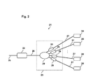
- FIG 2 is a diagrammatic representation of a passive optical network 21 according to one embodiment of the invention.
- the passive optical network 21 shown in FIG 2 is a so-called metro-access network by which data from a public optical fiber network 25 are distributed to a plurality of user units 24 also called ONU (Optical Network Unit).
- the optical network comprises an OLT 22 (Optical Line Terminal) as access point, which is the transmission interface between the passive optical network 21 and the overlying public optical fiber network 25.
- the passive optical network 21 comprises a splitting unit 23 which connects a central cable 26 coming from the OLT 22 to a plurality of arms 27, each arm 27 ending at an ONU 24.
- Each ONU 24 may represent a single subscriber, and in FIG 2 , as an example, only four ONUs 24 are shown for the purpose of a clearer representation. However, more than 256 ONUs 24 may be connected to a single splitting unit 23.
- the splitting unit 23 comprises an optical splitter 29, for connecting the central cable 26 to the plurality of arms 27, and a plurality of switch units 28 for coupling and decoupling the optical network units 24 with the optical splitter 29.
- the splitting unit 23 may comprise one switch unit 28 for each of the arm 27.
- each ONU 24 is uniquely associated with an identification signal which, in one embodiment of the invention may be represented by a continuous wave optical signal modulated at a low frequency (e.g. kilo-Hertz to hundreds of Mega-Hertz), the frequency tone being the unique identifier of the single ONU 24.
- the identification signal may be also be represented by a sequence and, in particular, by a finite sequence.
- an ONU 24 sends a request for communication to the OLT 22, followed by a first signal which, if the ONU 24 is working properly, should correspond exactly to the identification signal (i.e. the continuous wave optical signal modulated at a low frequency).
- the splitting unit 23 detects the first signal sent by the specific ONU 24 and compares this detected first signal with the identification signal which corresponds to the specific ONU 24. If this comparing step corresponds to a match it means that the ONU 24 is working properly, i.e. no interference or attack occurred, and in this case splitting unit ensures that the connection to the ONU is established. Conversely, if the comparing step corresponds to a mismatch it means that the specific ONU 24 is not working properly, i.e.
- the splitting unit 23 decouples the specific ONU 24 from the passive optical network 21. Therefore, according to the present embodiment of the invention, the splitting unit 23 guarantees for the security of the network by checking the identification signal of each specific ONU 24 independently. As a consequence, a possible interference will be efficiently identified and rapidly removed by the splitting unit 23.
- FIG 3 is a diagrammatic representation of a switch unit 28 according to one embodiment of the invention.
- the switch unit 28 shown in FIG 3 is a particular implementation of the switch unit 28 shown in FIG 2 according to one embodiment of the invention and is suitable for coupling and decoupling a specific ONU 24 with the optical splitter 29 through the arm 27.
- the switch unit 28 shown in FIG 3 includes a first detecting element 34 for detecting the first signal sent by the ONU 24 through the arm 27, a first controlling means 33 for storing the identification signal in a first recording medium 37 and for comparing the detected first signal with the identification signal stored in the first recording medium 37 and a switching element 31 for coupling and decoupling the optical network unit from the optical splitter 29.
- the first detecting element 34 includes a frequency detector 36, a photodiode 35 coupled with the frequency detector 36 through the link 311 and a tap 32 coupled with the photodiode 35 through the link 312 for detecting the first signal in the arm 27.
- the first controlling means 33 is coupled with the frequency detector 36 through the control link 38 and with the switching element 31 through the control link 39.
- the ONU 24 sends a request for communication, containing a first signal which, if the ONU 24 is working properly, should correspond exactly to the identification signal (e.g. the continuous wave optical signal modulated at a low frequency).
- the first detecting element 34 detects the first signal sent by the specific ONU 24 through the tap 32 and the photodiode 35, while the frequency detector 36 detects the frequency tone included in the first signal.
- the first controlling means 33 which may be a switch control unit, compares the detected first signal with the identification signal related to the specific ONU 24 which is stored in the first recording medium 37 which corresponds to the specific ONU 24.
- this comparing step corresponds to a match it means that the ONU 24 is working properly, i.e. no interference or attack occurred, and in this case for the switching element 31 ensures that the connection to the ONU is established. Conversely, if the comparing step corresponds to a mismatch it means that the specific ONU 24 is not working properly, i.e. an interference or an attack occurred, and in this case the switching element 31 decouples the specific ONU 24 from the passive optical network 21.
- the first controlling means 33 compares the detected first signal with the identification signal related to the specific ONU 24 stored in the first recording medium 37, and if the comparing step corresponds to a match the switching element 31 ensures that the connection between the splitting unit 23 and the ONU 24 is established.
- the splitting unit 23 maintains the optical network unit (24) coupled with the splitting unit if the comparing step results in a match or recouples the optical network unit (24) with the splitting unit 23 if the optical network unit (24) is not coupled with the splitting unit (for example because the optical network unit 24 has been previously decoupled from the splitting unit) and the comparing step results in a match.
- the splitting unit 23, and in particular the switch unit 28 guarantees for the security of the network by checking the identification signal of each specific ONU 24 independently. As a consequence, a possible interference will be efficiently identified and rapidly removed by the switch unit 28.
- the embodiment of the invention shown in FIG 3 can be implemented in different ways.
- the implementation may require the use of tap couplers, photodiodes and optical switches.
- the optical switching element 31 may be designed as "Normally Closed" (NC) component wherein the specific arm 27 is connected to the passive optical network if no electrical signal is applied to the switching element 31.
- NC normally Closed
- PLC Planar Lightwave Circuits
- the switching functionality may be obtained by means of a thermal effect which may require a heather element for the switch unit 28.
- the identification signal may be represented by a continuous wave optical signal modulated at a low frequency (e.g. kilo-Hertz to hundreds of Mega-Hertz), the frequency tone being the unique identifier of the single ONU 24.
- CW may represent a continuous wave (e.g. the continuous wave generated by the ONU 24 laser), v 0 being a low frequency tone, t being the time, T being the duration of the identification signal, and rect t T being a function being equal to one for - T 2 ⁇ t ⁇ T 2 and being equal to zero elsewhere.
- CW term since the CW term is constant, it will be neglected without loss of generality.
- TotalBandwidth n sp ⁇ 2 ⁇ n T
- n sp represents the number of ONUs 24 of the splitting unit (i.e. the splitting ratio).
- v 0 is assumed to be representative of the frequency range of the ensemble of the low frequency signals related to the arms of the splitting unit. It is worthwhile to note, that for tone frequencies in the MHz range, relative accuracies below 1% can be achieved by keeping the duration T 51 of the identification signal below 1ms, so that the overall performance of the network is almost unaffected.
- FIG 6 is a diagrammatic representation of a passive optical network 61 according to one embodiment of the invention.
- the passive optical network 61 shown in FIG 6 is a so-called metro-access network by which data from a public optical fiber network are distributed to a plurality of user units 24 also called ONU (Optical Network Unit).
- the optical network comprises an OLT 22 (Optical Line Terminal) as access point, which is the transmission interface between the passive optical network 61 and the overlying public optical backbone fiber network.
- the passive optical network 61 comprises a splitting unit 23 which connects a central cable 26 coming from the OLT 22 to a plurality of arms 27, each arm 27 ending at an ONU 24.
- Each ONU 24 may represent a single subscriber, and in FIG 6 , as an example, only four ONUs 24 are shown for the purpose of a clearer representation. However, more than 256 ONUs 24 may be connected to a single splitting unit 23.
- the OLT 22 further comprises a second detecting element 62 which includes a frequency detector 64, a photodiode 65 coupled with the frequency detector 64 through the link 618 and a tap 615 coupled with the photodiode 65 through the link 619 for detecting the first signal in each of the upstream signals 613.
- the second detecting element 62, and in particular its frequency detector 64 is further coupled through the control link 617 with a second controlling means 69 which is suitable for storing the identification signal in a second recording medium 69 and for comparing the detected first signal with the identification signal stored in the second recording medium 69.
- the OLT 22 further comprises an optical port 68 for the supervisory channel to convey this channel from the optical line terminal 22 with the splitting unit 23.
- the supervisory channel is an Unidirectional Optical Supervisory Channel (OSC) and transport control information from the second controlling means 69 to the splitting unit 23 through the multiplexer/demultiplexer 616 and the central cable 26 so that the Unidirectional Optical Supervisory Channel (OSC) is multiplexed by together with the downstream signal (is usually one signal/wavelength) 614 in the central cable 26.
- OSC Unidirectional Optical Supervisory Channel
- CWDM Coarse Wavelength Division Multiplexing
- AWG Array Waveguide Grating
- the splitting unit 23 comprises a demultiplexer 611 for demultiplexing the Unidirectional Optical Supervisory Channel (OSC) 68 and the cable conveying the downstream and upstream signals 612.
- the splitting unit 23 further comprises an optical splitter 29 for connecting the cable conveying the downstream and upstream signals 612 to the plurality of arms 27, and a plurality of switch units 28 for coupling and decoupling the optical network units 24 with the optical splitter 29.
- the splitting unit 23 may comprise one switch unit 28 for each of the arm 27.
- the splitting unit 23 further comprises an optical supervisory channel detection unit 66 for detecting the signals conveyed in the Optical Supervisory Channel, and an Optical Supervisory Channel switch control unit 67 coupled with the Optical Supervisory Channel detection unit 66 through the link 620 for controlling the coupling and de-coupling operation of the switch units 28 and linked to these switch units 28 through the control links 621.
- the identification signal further comprises an acknowledgment data packet. Therefore, in the present embodiment, the identification signal comprises a continuous wave optical signal modulated at a low frequency represented for example by the formula (1), and an acknowledgment data packet conveying information to be compared with the one stored in the second recording medium 69 (e.g. in a look-up table).
- the ONU 24 sends a request for communication, beginning with the identification signal (e.g. the continuous wave optical signal modulated at a low frequency), followed by data packets including acknowledgements data packets detected by means of a receiver connected to line 613 but not shown in the diagram.
- the identification signal e.g. the continuous wave optical signal modulated at a low frequency
- data packets including acknowledgements data packets detected by means of a receiver connected to line 613 but not shown in the diagram.
- the comparing step includes comparing both the frequency tone related to the continuous wave optical signal modulated at a low frequency and the acknowledgment data packet.
- the present embodiment allows the detection and the removal of interference also in the case in which the first signal includes a matching frequency tone but a wrong acknowledgment data packet.
- the OLT 22 still guarantees for the security of the network by checking the identification signal of each specific ONU 24 independently, while the splitting unit 23, and in particular the switch unit 28, merely executes the requests to decouple the ONU 24 from the network if an interference occurs.
- the identification signal can be changed and updated on a regular basis, in particular the tone frequency of the continuous wave optical signal modulated at a low frequency can be changed and updated regularly.
- the OLT 22 updates the tone frequency related to a particular ONU 24 and stores the new value in the second recording medium 69, at the same time the OLT sends the updated tone frequency related to a particular ONU 24 to the splitting unit (23) through the supervisory channel via the link 68 and the splitting unit (23) stores the updated identification signal in the first recording medium (37), contemporaneously the optical line terminal (22) sends the updated value of the frequency of the identification signal to the optical network unit (24) which sets the frequency of the new tone to the updated value.
- the number of arms 27 of the splitting unit 23 can be increased beyond the limitation imposed by the number of ports of AWG- Demultiplexers or CWDM-Demultiplexers.
- each OLT 22 is allowed to serve a higher number of ONUs 24 reducing in this way the reduced cost per arm 27.
- a further effect of some embodiments of the invention is that no spectrally separated optical control signals are required to control the connection of each arm 27, so that the number of ports can be increased without the use of demultiplexer (AWGs or CWDM filters). As a consequence, neither an array of fixed wavelength laser nor tuneable lasers are necessary in the OLT 22.
- a further effect of some embodiments of the invention is that the OLT does not require an optical amplifier and the related requirement on the maximum allowed distance between the OLT 22 and the splitting unit 23 becomes unnecessary.
- a further effect of some embodiments of the invention is the capability to exclude each port from the network separately.
- the number of ONUs 24 served by a single OLT 22 can be increased to 256 or beyond by simultaneously guaranteeing the possibility to disconnect each individual port.
- a further effect of some embodiments of the invention is that the splitting unit 23 guarantees for the security of the network by checking the identification signal of each arm 27 independently. As a consequence, an attacking port will be identified in a fast way by the splitting unit 23. As a further consequence, the attacking port does not need necessarily to be identified by the OLT 22 and a corresponding procedure is intrinsically not necessary.
Landscapes
- Engineering & Computer Science (AREA)
- Computer Networks & Wireless Communication (AREA)
- Signal Processing (AREA)
- Physics & Mathematics (AREA)
- Electromagnetism (AREA)
- Computer Security & Cryptography (AREA)
- Computing Systems (AREA)
- Optical Communication System (AREA)
Abstract
A method for removing signal interference in a passive optical network, the passive optical network including an optical line terminal, a splitting unit coupled with the optical line terminal, an optical network unit coupled with the splitting unit, and an identification signal uniquely associated with the optical network unit; the method comprising the steps of sending a first signal, detecting the first signal, comparing the detected first signal with the identification signal and decoupling the optical network unit from the splitting unit if the comparing step results in a mismatch.
Description
- The invention refers to an apparatus for preventing signal interference in a passive optical network and to a corresponding method for removing signal interference in a passive optical network.
- Passive Optical Networks (PON) are networks of optical fiber lines in which optical light signals are transmitted and distributed without interposition of active amplifying components.
-
FIG 1 is a diagrammatic representation of a conventional passiveoptical network 1. The passiveoptical network 1 shown is a so-called metro-access network by which data from a publicoptical fiber network 5 are distributed to a plurality ofuser units 4 also called ONU (Optical Network Unit). The optical network comprises a so-called OLT 2 (Optical Line Terminal) as access point, which is the transmission interface between the passiveoptical network 1 and the overlying public opticalbackbone fiber network 5. Moreover, the passiveoptical network 1 comprises a splittingunit 3 which connects acentral cable 6 coming from theOLT 2 to a plurality ofarms 7, eacharm 7 ending at an ONU 4. - Conventional PONs are bidirectional networks, in particular they distribute downstream traffic from the optical line terminal (OLT) to optical network units (ONUs) in a broadcast manner while the ONUs send upstream data packets.
- In fiber-optic communications, wavelength-division multiplexing (WDM) is a technology which multiplexes multiple optical carrier signals on a single optical fiber by using different wavelengths of laser light to carry different signals. This allows for a multiplication in capacity, in addition to enabling bidirectional communications over one strand of fiber.
- Conventionally passive optical networks use a specific wavelength for downstream communication (from the OLT to the ONUs) whereas for upstream traffic (from the ONUs to the OLT) different solutions are known in the art. According to one known solution all ONUs transmit over the same wavelength (time division multiplexing technique), whereas, according to another known solution, wavelength-division multiplexing (WDM) is employed (the so-called WDM-PON approach). However, in both architectures the same OLT and the same central cable are shared by a plurality of ONUs
- Unfortunately, in such passive optical networks, interference in a single ONU can cause a collapse of the entire access network during a data transmission from the ONUs to the OLT whenever a disturbed signal coming from an ONU reaches the central cable and there causes a disturbed overall signal which can no longer be processed correctly.
- A particularly critical situation is given when a single ONU starts to transmit permanently or casually light at a wavelength reserved for the upstream communication of another ONU. Especially for networks using a single wavelength for the shared upstream information flow, this would mean that the communication between ONUs and OLT is significantly affected or even impossible.
- As a consequence, although the opposite direction (OLT to ONUs) is still working properly, the operation of the PON would be significantly limited or even interrupted. With the increasing number of user units (ONUs) connected to a single OLT this scenario would be particularly inconvenient for the enterprise users or wireless network operators.
- These disturbances are usually referred to as attacks, even if these events are not necessarily restricted to intentional activities.
- When such signal interference occurs in conventional optical networks, the fault must be eliminated by a service technician who examines and individually disconnects the individual arms at the splitting unit of the optical network until the causal fault has been found. This procedure can be very time-consuming and leads to a long failure time of the optical network.
- A large number of methods for removing signal interference in a passive optical network (PON) are known from the prior art. In one known method, for example, the restoration of the path affected by the attack includes the manual substitution of hardware elements, which can be very time-consuming and leads to a long re-activation time. In other known methods the disconnection of the ONU affected by the attack includes the simultaneous disconnection of an entire group of users, which could be particularly inconvenient for the enterprise users or wireless network operators.
- Based upon the above discussions, it is concluded that there is a need in the art, for an improved method and apparatus for removing signal interference in a passive optical network (PON). The improved method should be capable of removing signal interference or injection attacks in a passive optical network in an effective and automated way without that the removal of the interference causes the disconnection of an entire group of users.
- In order to overcome the above-described need in the art, the present invention discloses a method for removing signal interference in a passive optical network, the passive optical network including an optical line terminal, a splitting unit coupled with the optical line terminal, an optical network unit coupled with the splitting unit, and an identification signal uniquely associated with the optical network unit; the method comprising the following steps: sending a first signal, detecting the first signal; comparing the detected first signal with the identification signal decoupling the optical network unit from the splitting unit if the comparing step results in a mismatch.
- In a next embodiment the method further comprises the step in which the optical network unit sends the first signal.
- In other embodiments of the present invention the method further comprises the step according to which the splitting unit detects the first signal, compares the detected first signal with the identification signal and decouples the optical network unit from the splitting unit if the comparing step results in a mismatch.
- In other embodiments of the present invention the method further comprises the step according to which the splitting unit maintains the optical network unit coupled with the splitting unit if the comparing step results in a match.
- In a further embodiment the method further comprises the step according to which the splitting unit recouples the optical network unit with the splitting unit if the optical network unit is not coupled with the splitting unit and the comparing step results in a match.
- In a further embodiment the method further comprises the step according to which switching element maintains the optical network unit decoupled from the splitting unit if the optical network unit is not coupled with the splitting unit and if the comparing step in the first controlling means results in a mismatch
- It is also an embodiment, that the splitting unit further comprises a switch unit for coupling and re-coupling the optical network unit with the splitting unit and for decoupling the optical network unit from the splitting unit.
- In a further embodiment, the switch unit further comprises a first detecting element for detecting the first signal, a first controlling means for storing the identification signal in a first recording medium and for comparing the detected first signal with the identification signal stored in the first recording medium and a switching element for coupling and re-coupling the optical network unit with the splitting unit and for decoupling the optical network unit from the splitting unit.
- In other embodiments of the present invention the method further comprises the steps according to which the first detecting element detects the first signal, the first controlling means compares the detected first signal with the identification signal stored in the first recording medium, and the switching element decouples the optical network unit from the splitting unit if the comparing step in the first controlling means results in a mismatch.
- In a further embodiment, the method further comprises the step according to which the switching element maintains the optical network unit coupled with the splitting unit if the comparing step in the first controlling means results in a match.
- In a further embodiment the method further comprises the step according to which the switching element recouples the optical network unit with the splitting unit if the optical network unit is not coupled with the splitting unit and if the comparing step in the first controlling means results in a match.
- It is also an embodiment, that the optical line terminal comprises a second detecting element for detecting the first signal, and a second controlling means for storing the identification signal in a second recording medium and for comparing the detected first signal with the identification signal stored in the second recording medium.
- It is also an embodiment, that the passive optical network further comprises a supervisory channel linking the optical line terminal with the splitting unit.
- In a further embodiment, the method further comprises the following steps: the second detecting element detects the first signal, the second controlling means compares the detected first signal with the identification signal stored in the second recording medium, and the optical line terminal sends through the supervisory channel a request to the splitting unit to decouple the optical network unit from the splitting unit if the comparing step in the second controlling means results in a mismatch.
- In a next embodiment, the identification signal comprises a continuous wave optical signal modulated at a low frequency.
- In an alternative embodiment of the invention, the continuous wave optical signal modulated at a low frequency (41) is expressed by the following:

- CW being a constant term representing a continuous wave, v0 being a low frequency tone, t being the time, T being the duration of the identification signal, and rect


- It is also an embodiment, that the identification signal further comprises an acknowledgment data packet.
- In a further embodiment, the method further comprises the following steps: the optical line terminal stores an updated identification signal in the second recording medium, the optical line terminal sends the updated identification signal to the splitting unit through the supervisory channel, the splitting unit stores the updated identification signal in the first recording medium and the optical line terminal sends the updated identification signal to the optical network unit.
- The problem stated above is also solved by a system for removing signal interference in a passive optical network, comprising: an optical line terminal, a splitting unit coupled with the optical line terminal, an optical network unit coupled with the splitting unit, an identification signal uniquely associated with the optical network unit, wherein the optical network unit is configured to send a first signal and the splitting unit is configured to detect the first signal, compare the detected first signal with the identification signal and decouple the optical network unit from the splitting unit if the comparing results in a mismatch.
- The invention is explained by way of example in more detail below with the aid of the attached drawings.
-
FIG 1 is a diagrammatic representation of a conventional passive optical network; -
FIG 2 is a diagrammatic representation of a passive optical network according to one embodiment of the invention; -
FIG 3 is a diagrammatic representation of a switch unit according to one embodiment of the invention; -
FIG 4 is a representation of the normalized Fourier transform of the identification signal versus frequency difference (v-v =) according to one embodiment of the invention; -
FIG 5 is a representation of the required duration T of the identification signal versus frequency according to one embodiment of the invention. -
FIG 6 is a diagrammatic representation of a passive optical network according to one embodiment of the invention. - As regards the description of
FIG 1 , reference is made to the background of the invention. - Illustrative embodiments will now be described with reference to the accompanying drawings to disclose the teachings of the present invention. While the present invention is described herein with reference to illustrative embodiments for particular applications, it should be understood that the invention is not limited thereto. Those having ordinary skill in the art and access to the teachings provided herein will recognize additional modifications, applications, and embodiments within the scope thereof and additional fields in which the present invention would be of significant utility.
-
FIG 2 is a diagrammatic representation of a passiveoptical network 21 according to one embodiment of the invention. The passiveoptical network 21 shown inFIG 2 is a so-called metro-access network by which data from a publicoptical fiber network 25 are distributed to a plurality ofuser units 24 also called ONU (Optical Network Unit). The optical network comprises an OLT 22 (Optical Line Terminal) as access point, which is the transmission interface between the passiveoptical network 21 and the overlying publicoptical fiber network 25. Moreover, the passiveoptical network 21 comprises a splittingunit 23 which connects acentral cable 26 coming from the OLT 22 to a plurality ofarms 27, eacharm 27 ending at an ONU 24. EachONU 24 may represent a single subscriber, and inFIG 2 , as an example, only fourONUs 24 are shown for the purpose of a clearer representation. However, more than 256ONUs 24 may be connected to asingle splitting unit 23. In the embodiment of the invention shown inFIG 2 , the splittingunit 23 comprises anoptical splitter 29, for connecting thecentral cable 26 to the plurality ofarms 27, and a plurality ofswitch units 28 for coupling and decoupling theoptical network units 24 with theoptical splitter 29. In particular, the splittingunit 23 may comprise oneswitch unit 28 for each of thearm 27. - In the present invention each
ONU 24 is uniquely associated with an identification signal which, in one embodiment of the invention may be represented by a continuous wave optical signal modulated at a low frequency (e.g. kilo-Hertz to hundreds of Mega-Hertz), the frequency tone being the unique identifier of thesingle ONU 24. In other embodiments of the invention the identification signal may be also be represented by a sequence and, in particular, by a finite sequence. - During normal operation an
ONU 24 sends a request for communication to theOLT 22, followed by a first signal which, if theONU 24 is working properly, should correspond exactly to the identification signal (i.e. the continuous wave optical signal modulated at a low frequency). The splittingunit 23 detects the first signal sent by thespecific ONU 24 and compares this detected first signal with the identification signal which corresponds to thespecific ONU 24. If this comparing step corresponds to a match it means that theONU 24 is working properly, i.e. no interference or attack occurred, and in this case splitting unit ensures that the connection to the ONU is established. Conversely, if the comparing step corresponds to a mismatch it means that thespecific ONU 24 is not working properly, i.e. an interference or an attack occurred, and in this case the splittingunit 23 decouples thespecific ONU 24 from the passiveoptical network 21. Therefore, according to the present embodiment of the invention, the splittingunit 23 guarantees for the security of the network by checking the identification signal of eachspecific ONU 24 independently. As a consequence, a possible interference will be efficiently identified and rapidly removed by the splittingunit 23. -
FIG 3 is a diagrammatic representation of aswitch unit 28 according to one embodiment of the invention. Theswitch unit 28 shown inFIG 3 is a particular implementation of theswitch unit 28 shown inFIG 2 according to one embodiment of the invention and is suitable for coupling and decoupling aspecific ONU 24 with theoptical splitter 29 through thearm 27. Theswitch unit 28 shown inFIG 3 includes a first detectingelement 34 for detecting the first signal sent by theONU 24 through thearm 27, a first controlling means 33 for storing the identification signal in afirst recording medium 37 and for comparing the detected first signal with the identification signal stored in thefirst recording medium 37 and a switchingelement 31 for coupling and decoupling the optical network unit from theoptical splitter 29. Moreover, the first detectingelement 34 includes afrequency detector 36, aphotodiode 35 coupled with thefrequency detector 36 through thelink 311 and atap 32 coupled with thephotodiode 35 through thelink 312 for detecting the first signal in thearm 27. Moreover the first controlling means 33 is coupled with thefrequency detector 36 through thecontrol link 38 and with the switchingelement 31 through thecontrol link 39. - During normal operation the
ONU 24 sends a request for communication, containing a first signal which, if theONU 24 is working properly, should correspond exactly to the identification signal (e.g. the continuous wave optical signal modulated at a low frequency). The first detectingelement 34 detects the first signal sent by thespecific ONU 24 through thetap 32 and thephotodiode 35, while thefrequency detector 36 detects the frequency tone included in the first signal. The first controlling means 33, which may be a switch control unit, compares the detected first signal with the identification signal related to thespecific ONU 24 which is stored in thefirst recording medium 37 which corresponds to thespecific ONU 24. - If this comparing step corresponds to a match it means that the
ONU 24 is working properly, i.e. no interference or attack occurred, and in this case for the switchingelement 31 ensures that the connection to the ONU is established. Conversely, if the comparing step corresponds to a mismatch it means that thespecific ONU 24 is not working properly, i.e. an interference or an attack occurred, and in this case the switchingelement 31 decouples thespecific ONU 24 from the passiveoptical network 21. - As soon as the interference or the attack has been removed, and the
specific ONU 24 sends a new request for communication, containing a first signal, this new request together with the first signal is detected again from the first detectingelement 34. Consequently the first controlling means 33 compares the detected first signal with the identification signal related to thespecific ONU 24 stored in thefirst recording medium 37, and if the comparing step corresponds to a match the switchingelement 31 ensures that the connection between the splittingunit 23 and theONU 24 is established. In particular the splittingunit 23 maintains the optical network unit (24) coupled with the splitting unit if the comparing step results in a match or recouples the optical network unit (24) with thesplitting unit 23 if the optical network unit (24) is not coupled with the splitting unit (for example because theoptical network unit 24 has been previously decoupled from the splitting unit) and the comparing step results in a match. - Therefore, according to the present embodiment of the invention, the splitting
unit 23, and in particular theswitch unit 28, guarantees for the security of the network by checking the identification signal of eachspecific ONU 24 independently. As a consequence, a possible interference will be efficiently identified and rapidly removed by theswitch unit 28. - The embodiment of the invention shown in
FIG 3 can be implemented in different ways. As shown inFIG 3 the implementation may require the use of tap couplers, photodiodes and optical switches. In particular theoptical switching element 31 may be designed as "Normally Closed" (NC) component wherein thespecific arm 27 is connected to the passive optical network if no electrical signal is applied to the switchingelement 31. The use of discrete components and micro-optics may represent an option as well as the use of Planar Lightwave Circuits (PLC) which offers several advantages like, for example, reduced size, reduced costs due the capability of integrating several optical components, and low power supply. In the PLC configuration, the switching functionality may be obtained by means of a thermal effect which may require a heather element for theswitch unit 28. -
FIG 4 is a representation of the normalized Fourier transform S+(v) 41 of the identification signal versus frequency difference (v-v =) 42 according to one embodiment of the invention. In the present embodiment, the identification signal may be represented by a continuous wave optical signal modulated at a low frequency (e.g. kilo-Hertz to hundreds of Mega-Hertz), the frequency tone being the unique identifier of thesingle ONU 24. - In particular, in the present embodiment, the continuous wave optical signal modulated at a low frequency 41) may be expressed by the following formula:

- Where CW may represent a continuous wave (e.g. the continuous wave generated by the
ONU 24 laser), v 0 being a low frequency tone, t being the time, T being the duration of the identification signal, and rect

- The Fourier transform of the continuous wave optical signal modulated at a low frequency is:


- S(v) is a symmetric function around the zero frequency, so that in the following only its normalized part:

will be analyzed. - In
FIG 4 , the normalized Fourier transform S +(v) 41 of the continuous wave optical signal modulated at a low frequency is shown for different values of the duration T of the identification signal, in particular for T=0.0001sec 45 and for T=0.002sec 44. It can be seen that thespectrum 41 becomes narrower when increasing T, making the identification of the frequency easier for the splitting unit. - The zeros of S+(v) are located at the following frequencies:

n being an integer number, with n≠0 - In order to obtain a quantification of the minimum required duration T of the identification signal, the relative uncertainty on the peak frequency δv is defined as ratio between the interval between the zero of order n and -n and v 0, that can be expressed as

And therefore
i.e. at a given frequency v0 the required duration T of the identification signal increases by decreasing δv. - Furthermore, the larger the uncertainty δv is, the larger the electrical bandwidth required by the ensemble of the pilot tones will be. Based on the above analysis, the minimum value of the total required electrical bandwidth can be computed as follows:

Where nsp represents the number ofONUs 24 of the splitting unit (i.e. the splitting ratio). - The duration T of the identification signal can be expressed in terms of number (nT) of periods of the pilot tone, leading to:


- These relationships indicate that the relative accuracy depends only on the number of periods contained in the identification signal and not on the absolute value of the tone frequency. As a consequence, for a given accuracy, the duration of the identification signal can be reduced by increasing the frequency of the pilot tone v0 at the expense of an increased total electrical bandwidth.
-
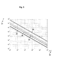
FIG 5 is a representation of the requiredduration T 51 of the identification signal versusfrequency 52 according to one embodiment of the invention and for n=3, and δv=1% 53, δv=5% 54, δv=10% 55, δv=30% 56 as a function of the lowfrequency tone v 0 52. For this evaluation, v0 is assumed to be representative of the frequency range of the ensemble of the low frequency signals related to the arms of the splitting unit. It is worthwhile to note, that for tone frequencies in the MHz range, relative accuracies below 1% can be achieved by keeping theduration T 51 of the identification signal below 1ms, so that the overall performance of the network is almost unaffected. -
FIG 6 is a diagrammatic representation of a passiveoptical network 61 according to one embodiment of the invention. The passiveoptical network 61 shown inFIG 6 is a so-called metro-access network by which data from a public optical fiber network are distributed to a plurality ofuser units 24 also called ONU (Optical Network Unit). The optical network comprises an OLT 22 (Optical Line Terminal) as access point, which is the transmission interface between the passiveoptical network 61 and the overlying public optical backbone fiber network. Moreover, the passiveoptical network 61 comprises asplitting unit 23 which connects acentral cable 26 coming from theOLT 22 to a plurality ofarms 27, eacharm 27 ending at anONU 24. EachONU 24 may represent a single subscriber, and inFIG 6 , as an example, only fourONUs 24 are shown for the purpose of a clearer representation. However, more than 256ONUs 24 may be connected to asingle splitting unit 23. TheOLT 22, according to the present embodiment of the invention, comprises a multiplexer/demultiplexer 616 for multiplexing the downstream signal travelling along theoptical link 614 to thecentral cable 26 and for demultiplexing a plurality ofupstream signals 615 coming from the samecentral cable 26. TheOLT 22, according to the present embodiment of the invention, further comprises a second detectingelement 62 which includes afrequency detector 64, aphotodiode 65 coupled with thefrequency detector 64 through thelink 618 and atap 615 coupled with thephotodiode 65 through the link 619 for detecting the first signal in each of the upstream signals 613. The second detectingelement 62, and in particular itsfrequency detector 64, is further coupled through thecontrol link 617 with a second controlling means 69 which is suitable for storing the identification signal in asecond recording medium 69 and for comparing the detected first signal with the identification signal stored in thesecond recording medium 69. TheOLT 22, according to the present embodiment of the invention, further comprises anoptical port 68 for the supervisory channel to convey this channel from theoptical line terminal 22 with thesplitting unit 23. In particular the supervisory channel is an Unidirectional Optical Supervisory Channel (OSC) and transport control information from the second controlling means 69 to thesplitting unit 23 through the multiplexer/demultiplexer 616 and thecentral cable 26 so that the Unidirectional Optical Supervisory Channel (OSC) is multiplexed by together with the downstream signal (is usually one signal/wavelength) 614 in thecentral cable 26. - Conventional Coarse Wavelength Division Multiplexing (CWDM) filters and Array Waveguide Grating (AWG) base components can be used to implement the multiplexer/
demultiplexer unit 616 and thedemultiplexer unit 611. - In the present embodiment of the invention, the splitting
unit 23 comprises ademultiplexer 611 for demultiplexing the Unidirectional Optical Supervisory Channel (OSC) 68 and the cable conveying the downstream andupstream signals 612. The splittingunit 23 further comprises anoptical splitter 29 for connecting the cable conveying the downstream andupstream signals 612 to the plurality ofarms 27, and a plurality ofswitch units 28 for coupling and decoupling theoptical network units 24 with theoptical splitter 29. In particular, the splittingunit 23 may comprise oneswitch unit 28 for each of thearm 27. The splittingunit 23 further comprises an optical supervisorychannel detection unit 66 for detecting the signals conveyed in the Optical Supervisory Channel, and an Optical Supervisory Channelswitch control unit 67 coupled with the Optical SupervisoryChannel detection unit 66 through thelink 620 for controlling the coupling and de-coupling operation of theswitch units 28 and linked to theseswitch units 28 through the control links 621. - According to the present embodiment of the invention, as shown in
FIG 6 , the identification signal further comprises an acknowledgment data packet. Therefore, in the present embodiment, the identification signal comprises a continuous wave optical signal modulated at a low frequency represented for example by the formula (1), and an acknowledgment data packet conveying information to be compared with the one stored in the second recording medium 69 (e.g. in a look-up table). - According to the present embodiment of the invention, during normal operation the
ONU 24 sends a request for communication, beginning with the identification signal (e.g. the continuous wave optical signal modulated at a low frequency), followed by data packets including acknowledgements data packets detected by means of a receiver connected to line 613 but not shown in the diagram. In this way, the information contained in the acknowledgement data packets and indicating which ONU is sending the request is extracted by theOLT 22. In the present embodiment the comparing step includes comparing both the frequency tone related to the continuous wave optical signal modulated at a low frequency and the acknowledgment data packet. - As an effect, the present embodiment allows the detection and the removal of interference also in the case in which the first signal includes a matching frequency tone but a wrong acknowledgment data packet. According to the present embodiment of the invention, the
OLT 22 still guarantees for the security of the network by checking the identification signal of eachspecific ONU 24 independently, while thesplitting unit 23, and in particular theswitch unit 28, merely executes the requests to decouple theONU 24 from the network if an interference occurs. - According to another embodiment of the invention, which can be also represented in
FIG 6 , the identification signal can be changed and updated on a regular basis, in particular the tone frequency of the continuous wave optical signal modulated at a low frequency can be changed and updated regularly. According to the present embodiment, theOLT 22 updates the tone frequency related to aparticular ONU 24 and stores the new value in thesecond recording medium 69, at the same time the OLT sends the updated tone frequency related to aparticular ONU 24 to the splitting unit (23) through the supervisory channel via thelink 68 and the splitting unit (23) stores the updated identification signal in the first recording medium (37), contemporaneously the optical line terminal (22) sends the updated value of the frequency of the identification signal to the optical network unit (24) which sets the frequency of the new tone to the updated value. - One of the effects of some embodiments of the invention, is that the number of
arms 27 of thesplitting unit 23 can be increased beyond the limitation imposed by the number of ports of AWG- Demultiplexers or CWDM-Demultiplexers. Thus, eachOLT 22 is allowed to serve a higher number ofONUs 24 reducing in this way the reduced cost perarm 27. - A further effect of some embodiments of the invention, is that no spectrally separated optical control signals are required to control the connection of each
arm 27, so that the number of ports can be increased without the use of demultiplexer (AWGs or CWDM filters). As a consequence, neither an array of fixed wavelength laser nor tuneable lasers are necessary in theOLT 22. - A further effect of some embodiments of the invention, is that the OLT does not require an optical amplifier and the related requirement on the maximum allowed distance between the
OLT 22 and thesplitting unit 23 becomes unnecessary. - A further effect of some embodiments of the invention, is the capability to exclude each port from the network separately. In the present invention the number of
ONUs 24 served by asingle OLT 22 can be increased to 256 or beyond by simultaneously guaranteeing the possibility to disconnect each individual port. - A further effect of some embodiments of the invention, is that the
splitting unit 23 guarantees for the security of the network by checking the identification signal of eacharm 27 independently. As a consequence, an attacking port will be identified in a fast way by the splittingunit 23. As a further consequence, the attacking port does not need necessarily to be identified by theOLT 22 and a corresponding procedure is intrinsically not necessary.
Claims (18)
- A method for removing signal interference in a passive optical network (21), the passive optical network including an optical line terminal (22), a splitting unit (23) coupled with the optical line terminal (22), an optical network unit (24) coupled with the splitting unit (23), and an identification signal uniquely associated with the optical network unit (24); the method comprising the following steps:- sending a first signal;- detecting the first signal;- comparing the detected first signal with the identification signal;- decoupling the optical network unit from the splitting unit if the comparing step results in a mismatch.
- A method as claim 1, further comprising:the optical network unit (24) sending the first signal.
- A method as in any of the preceding claims 1 to 2, further comprising:the splitting unit (23) detecting the first signal, comparing the detected first signal with the identification signal and decoupling the optical network unit (24) from the splitting unit (23) if the comparing step results in a mismatch.
- A method as in any of the preceding claims 1 to 3, further comprising the following step:- the splitting unit (23) maintaining the optical network unit (24) coupled with the splitting unit if the comparing step results in a match.
- A method as in any of the preceding claims 1 to 3, further comprising the following step:the splitting unit (23) recoupling the optical network unit (24) with the splitting unit (23) if the optical network unit (24) is not coupled with the splitting unit and the comparing step results in a match.
- A method as in any of the preceding claims 1 to 5, wherein the splitting unit further comprises a switch unit (28) for coupling and re-coupling the optical network unit (24) with the splitting unit (23) and for decoupling the optical network unit (24) from the splitting unit (23).
- A method as in claim 6, wherein the switch unit further comprises a first detecting element (34) for detecting the first signal, a first controlling means (33) for storing the identification signal in a first recording medium (37) and for comparing the detected first signal with the identification signal stored in the first recording medium (37) and a switching element (31) for coupling and re-coupling the optical network unit (24) with the splitting unit (23) and for decoupling the optical network unit (24) from the splitting unit (23).
- A method as in claim 7, wherein
the first detecting element (34) detects the first signal;
the first controlling means (33) compares the detected first signal with the identification signal stored in the first recording medium (37); and
the switching element (31) decouples the optical network unit (24) from the splitting unit (23) if the comparing step in the first controlling means (33) results in a mismatch; - A method as in claims 3 and 7 wherein
the switching element (31) maintains the optical network unit (24) coupled with the splitting unit (23) if the comparing step in the first controlling means (33) results in a match. - A method as in claims 3 and 7 wherein
the switching element (31) recouples the optical network unit (24) with the splitting unit (23) if the optical network unit (24) is not coupled with the splitting unit and if the comparing step in the first controlling means (33) results in a match. - A method as in any of the preceding claims 1 to 9, wherein the optical line terminal (22) comprises a second detecting element (62) for detecting the first signal, and a second controlling means (63) for storing the identification signal in a second recording medium (69) and for comparing the detected first signal with the identification signal stored in the second recording medium (69).
- A method as in any of the preceding claims 1 to 11, wherein the passive optical network (21, 61) further comprises a supervisory channel linking the optical line terminal (22) with the splitting unit (23).
- A method as in any of the preceding claims 10 to 12, wherein
the second detecting element (62) detects the first signal;
the second controlling means (63) compares the detected first signal with the identification signal stored in the second recording medium (69);
the optical line terminal (22) sends through the supervisory channel (68) a request to the splitting unit (23) to decouple the optical network unit (24) from the splitting unit (23) if the comparing step in the second controlling means (63) results in a mismatch. - A method as in any of the preceding claims 1 to 13, wherein the identification signal comprises a continuous wave optical signal modulated at a low frequency (41).
- A method as in claim 13, wherein the continuous wave optical signal modulated at a low frequency (41) is expressed by the following:

CW being a constant term representing a continuous wave, v0 being a low frequency tone, t being the time, T being the duration of the identification signal, and rect

- A method as in any of the preceding claims 13 to 15, wherein the identification signal further comprises an acknowledgment data packet.
- A method as in any of the preceding claims 12 to 16, further comprising:the optical line terminal (22) storing an updated identification signal in the second recording medium (69);the optical line terminal sending the updated identification signal to the splitting unit (23) through the supervisory channel;the splitting unit (23) storing the updated identification signal in the first recording medium (37);the optical line terminal (22) sending the updated identification signal to the optical network unit (24).
- A system for removing signal interference in a passive optical network (21, 61), comprising:an optical line terminal (22);a splitting unit (23) coupled with the optical line terminal;an optical network unit (24) coupled with the splitting unit;an identification signal uniquely associated with the optical network unit (24);wherein the optical network unit (24) is configured to send a first signal and the splitting unit (23) is configured to detect the first signal, compare the detected first signal with the identification signal and decouple the optical network unit (24) from the splitting unit (23) if the comparing results in a mismatch.
Priority Applications (5)
| Application Number | Priority Date | Filing Date | Title |
|---|---|---|---|
| EP09180178A EP2337247A1 (en) | 2009-12-21 | 2009-12-21 | Method and apparatus for preventing signal interference in a passive optical network |
| CN201080064411.7A CN102771067B (en) | 2009-12-21 | 2010-12-17 | Method and device for preventing signal interference in a passive optical network |
| US13/518,277 US8824891B2 (en) | 2009-12-21 | 2010-12-17 | Method and apparatus for preventing signal interference in a passive optical network |
| EP10803072.7A EP2517383B1 (en) | 2009-12-21 | 2010-12-17 | Method and apparatus for preventing signal interference in a passive optical network |
| PCT/EP2010/070021 WO2011076671A1 (en) | 2009-12-21 | 2010-12-17 | Method and apparatus for preventing signal interference in a passive optical network |
Applications Claiming Priority (1)
| Application Number | Priority Date | Filing Date | Title |
|---|---|---|---|
| EP09180178A EP2337247A1 (en) | 2009-12-21 | 2009-12-21 | Method and apparatus for preventing signal interference in a passive optical network |
Publications (1)
| Publication Number | Publication Date |
|---|---|
| EP2337247A1 true EP2337247A1 (en) | 2011-06-22 |
Family
ID=42201058
Family Applications (2)
| Application Number | Title | Priority Date | Filing Date |
|---|---|---|---|
| EP09180178A Withdrawn EP2337247A1 (en) | 2009-12-21 | 2009-12-21 | Method and apparatus for preventing signal interference in a passive optical network |
| EP10803072.7A Active EP2517383B1 (en) | 2009-12-21 | 2010-12-17 | Method and apparatus for preventing signal interference in a passive optical network |
Family Applications After (1)
| Application Number | Title | Priority Date | Filing Date |
|---|---|---|---|
| EP10803072.7A Active EP2517383B1 (en) | 2009-12-21 | 2010-12-17 | Method and apparatus for preventing signal interference in a passive optical network |
Country Status (4)
| Country | Link |
|---|---|
| US (1) | US8824891B2 (en) |
| EP (2) | EP2337247A1 (en) |
| CN (1) | CN102771067B (en) |
| WO (1) | WO2011076671A1 (en) |
Cited By (3)
| Publication number | Priority date | Publication date | Assignee | Title |
|---|---|---|---|---|
| US20140237021A1 (en) * | 2013-02-15 | 2014-08-21 | Broadcom Corporation | System and Method for Bandwidth-Delay-Product Decoupler |
| WO2015124174A1 (en) * | 2014-02-18 | 2015-08-27 | Telefonaktiebolaget L M Ericsson (Publ) | A security device for an optical network |
| EP3051759A4 (en) * | 2013-09-26 | 2017-06-07 | Nec Corporation | Optical reception device, optical transmission device, optical communication system, optical communication method, and storage medium with program stored thereon |
Families Citing this family (11)
| Publication number | Priority date | Publication date | Assignee | Title |
|---|---|---|---|---|
| CN103916191B (en) * | 2012-12-31 | 2017-05-10 | 上海贝尔股份有限公司 | Method and apparatus for optical access network |
| JP5858485B2 (en) * | 2013-03-04 | 2016-02-10 | Necプラットフォームズ株式会社 | Optical communication system, control method therefor, and optical distributor |
| CN103488140B (en) * | 2013-09-06 | 2016-01-20 | 华中科技大学 | The online inspection tour system of a kind of transmission line of electricity |
| US9749723B2 (en) * | 2015-03-05 | 2017-08-29 | Huawei Technologies Co., Ltd. | System and method for optical network |
| US9673897B2 (en) * | 2015-06-30 | 2017-06-06 | Viavi Solutions Deutschland Gmbh | Optical network test instrument including optical network unit identifier capture capability from downstream signals |
| WO2017139974A1 (en) * | 2016-02-19 | 2017-08-24 | Huawei Technologies Co., Ltd. | Optical channel monitoring using expanded-spectrum pilot tone |
| JP6383380B2 (en) * | 2016-04-27 | 2018-08-29 | アンリツ株式会社 | Mobile terminal test apparatus and test method |
| US10348438B2 (en) * | 2017-09-04 | 2019-07-09 | Huawei Technologies Co., Ltd. | Spur removal in pilot-tone OPM |
| US11463164B1 (en) * | 2020-07-24 | 2022-10-04 | Cable Television Laboratories, Inc. | Optical line terminal with out-of-band communication channel, and method for implementing |
| US20230327756A1 (en) * | 2020-09-11 | 2023-10-12 | Nippon Telegraph And Telephone Corporation | Communication monitoring apparatus and communication monitoring system |
| CN112383845B (en) * | 2020-11-09 | 2022-10-11 | 国网四川省电力公司成都供电公司 | Test circuit and method convenient for PON to access network link |
Citations (5)
| Publication number | Priority date | Publication date | Assignee | Title |
|---|---|---|---|---|
| US20040156635A1 (en) * | 2003-02-06 | 2004-08-12 | Nortel Networks Limited | Method and apparatus for the transmission fault detection in an access network |
| US20070133800A1 (en) * | 2005-12-08 | 2007-06-14 | Electronics & Telecommunications Research Institute | Method for setting security channel based on MPCP between OLT and ONUs in EPON, and MPCP message structure for controlling frame transmission |
| EP1887717A1 (en) * | 2006-08-10 | 2008-02-13 | Fujitsu Ltd. | Optical transmission method and device |
| JP2008118296A (en) * | 2006-11-01 | 2008-05-22 | Nippon Telegr & Teleph Corp <Ntt> | ONU remote automatic setting method in EPON system and ONU remote automatic setting system |
| WO2009143893A1 (en) * | 2008-05-29 | 2009-12-03 | Telecom Italia S.P.A. | Method for localizing an optical network termination in an optical access network |
Family Cites Families (2)
| Publication number | Priority date | Publication date | Assignee | Title |
|---|---|---|---|---|
| JP4860137B2 (en) * | 2004-11-12 | 2012-01-25 | 日本電気通信システム株式会社 | Optical access network method, optical access network, and optical switch for optical access network |
| DE102006029967B3 (en) * | 2006-04-20 | 2007-12-13 | Siemens Ag | Protective device for correcting signal interference in a passive optical network, as well as a passive optical network and method for correcting signal interference |
-
2009
- 2009-12-21 EP EP09180178A patent/EP2337247A1/en not_active Withdrawn
-
2010
- 2010-12-17 CN CN201080064411.7A patent/CN102771067B/en active Active
- 2010-12-17 WO PCT/EP2010/070021 patent/WO2011076671A1/en not_active Ceased
- 2010-12-17 EP EP10803072.7A patent/EP2517383B1/en active Active
- 2010-12-17 US US13/518,277 patent/US8824891B2/en active Active
Patent Citations (5)
| Publication number | Priority date | Publication date | Assignee | Title |
|---|---|---|---|---|
| US20040156635A1 (en) * | 2003-02-06 | 2004-08-12 | Nortel Networks Limited | Method and apparatus for the transmission fault detection in an access network |
| US20070133800A1 (en) * | 2005-12-08 | 2007-06-14 | Electronics & Telecommunications Research Institute | Method for setting security channel based on MPCP between OLT and ONUs in EPON, and MPCP message structure for controlling frame transmission |
| EP1887717A1 (en) * | 2006-08-10 | 2008-02-13 | Fujitsu Ltd. | Optical transmission method and device |
| JP2008118296A (en) * | 2006-11-01 | 2008-05-22 | Nippon Telegr & Teleph Corp <Ntt> | ONU remote automatic setting method in EPON system and ONU remote automatic setting system |
| WO2009143893A1 (en) * | 2008-05-29 | 2009-12-03 | Telecom Italia S.P.A. | Method for localizing an optical network termination in an optical access network |
Non-Patent Citations (1)
| Title |
|---|
| HARALD ROHDE ET AL: "Securing Passive Optical Networks Against Signal Injection Attacks", 29 May 2007, OPTICAL NETWORK DESIGN AND MODELING; [LECTURE NOTES IN COMPUTER SCIENCE;;LNCS], SPRINGER BERLIN HEIDELBERG, BERLIN, HEIDELBERG, PAGE(S) 96 - 100, ISBN: 978-3-540-72729-3, XP019060024 * |
Cited By (4)
| Publication number | Priority date | Publication date | Assignee | Title |
|---|---|---|---|---|
| US20140237021A1 (en) * | 2013-02-15 | 2014-08-21 | Broadcom Corporation | System and Method for Bandwidth-Delay-Product Decoupler |
| EP3051759A4 (en) * | 2013-09-26 | 2017-06-07 | Nec Corporation | Optical reception device, optical transmission device, optical communication system, optical communication method, and storage medium with program stored thereon |
| US9882671B2 (en) | 2013-09-26 | 2018-01-30 | Nec Corporation | Optical reception apparatus, optical transmission apparatus, optical communication system, optical communication method, and storage medium storing program |
| WO2015124174A1 (en) * | 2014-02-18 | 2015-08-27 | Telefonaktiebolaget L M Ericsson (Publ) | A security device for an optical network |
Also Published As
| Publication number | Publication date |
|---|---|
| EP2517383B1 (en) | 2016-08-24 |
| US20120275782A1 (en) | 2012-11-01 |
| CN102771067B (en) | 2016-05-25 |
| WO2011076671A1 (en) | 2011-06-30 |
| CN102771067A (en) | 2012-11-07 |
| EP2517383A1 (en) | 2012-10-31 |
| US8824891B2 (en) | 2014-09-02 |
Similar Documents
| Publication | Publication Date | Title |
|---|---|---|
| US8824891B2 (en) | Method and apparatus for preventing signal interference in a passive optical network | |
| US8554078B2 (en) | Passive optical network with plural optical line terminals | |
| US9660754B2 (en) | Method and devices for automatic tuning in WDM-PON | |
| US8369706B2 (en) | Open access service model using WDM-PON | |
| US8180223B2 (en) | System and method for extending reach in a passive optical network | |
| US8977127B2 (en) | Inter-optical line terminal (OLT) communication in multiple-OLT passive optical networks (PONs) | |
| US6597482B1 (en) | Multiplexing/demultiplexing apparatus for wavelength division multiplexed system and wavelength division multiplexed passive optical subscriber networks using the same apparatus | |
| US20090010648A1 (en) | Methods and apparatus for upgrading passive optical networks | |
| EP2806583B1 (en) | Optical fiber transmission system | |
| WO2011017348A1 (en) | Split/smart channel allocated wdm-pon architecture | |
| US20040184809A1 (en) | Optical transmission apparatus and an optical wavelength multiplex network therewith | |
| JP2008517529A (en) | Systems and apparatus for telecommunications carrier class WDMPON providing trunk protection with improved fiber usage, distance, and bandwidth | |
| Hilbk et al. | High capacity WDM overlay on a passive optical network | |
| US8565599B2 (en) | System and method for transmitting optical markers in a passive optical network system | |
| WO2004034621A2 (en) | A wavelenght-division-multiplexing passive optical network utilizing fiber fault detectors and/or wavelenght tracking components | |
| US20070189772A1 (en) | Hybrid passive optical network using wireless communication | |
| US20190097988A1 (en) | Communication device and communication method | |
| KR20070001869A (en) | Broadband communication network | |
| KR20090059018A (en) | Optical filtering device and optical communication system | |
| TW201214996A (en) | Architecture and protection method for passive optical network and structure for optical switch | |
| JPH11243372A (en) | Device and method for supervising disconnection of wavelength multiple optical signal |
Legal Events
| Date | Code | Title | Description |
|---|---|---|---|
| PUAI | Public reference made under article 153(3) epc to a published international application that has entered the european phase |
Free format text: ORIGINAL CODE: 0009012 |
|
| AK | Designated contracting states |
Kind code of ref document: A1 Designated state(s): AT BE BG CH CY CZ DE DK EE ES FI FR GB GR HR HU IE IS IT LI LT LU LV MC MK MT NL NO PL PT RO SE SI SK SM TR |
|
| AX | Request for extension of the european patent |
Extension state: AL BA RS |
|
| 17P | Request for examination filed |
Effective date: 20111222 |
|
| STAA | Information on the status of an ep patent application or granted ep patent |
Free format text: STATUS: THE APPLICATION IS DEEMED TO BE WITHDRAWN |
|
| 18D | Application deemed to be withdrawn |
Effective date: 20111223 |