EP2337244A1 - Method and device for homodyne reception of an optical signal - Google Patents
Method and device for homodyne reception of an optical signal Download PDFInfo
- Publication number
- EP2337244A1 EP2337244A1 EP10193549A EP10193549A EP2337244A1 EP 2337244 A1 EP2337244 A1 EP 2337244A1 EP 10193549 A EP10193549 A EP 10193549A EP 10193549 A EP10193549 A EP 10193549A EP 2337244 A1 EP2337244 A1 EP 2337244A1
- Authority
- EP
- European Patent Office
- Prior art keywords
- signal
- optical
- transmitted
- baseline
- wavelength
- Prior art date
- Legal status (The legal status is an assumption and is not a legal conclusion. Google has not performed a legal analysis and makes no representation as to the accuracy of the status listed.)
- Granted
Links
- 230000003287 optical effect Effects 0.000 title claims abstract description 93
- 238000000034 method Methods 0.000 title claims abstract description 21
- 230000001427 coherent effect Effects 0.000 claims description 30
- 230000010287 polarization Effects 0.000 claims description 18
- MARUHZGHZWCEQU-UHFFFAOYSA-N 5-phenyl-2h-tetrazole Chemical compound C1=CC=CC=C1C1=NNN=N1 MARUHZGHZWCEQU-UHFFFAOYSA-N 0.000 claims description 6
- 239000013078 crystal Substances 0.000 claims description 6
- 238000004891 communication Methods 0.000 claims description 4
- 238000001514 detection method Methods 0.000 description 8
- 238000010586 diagram Methods 0.000 description 6
- 230000010355 oscillation Effects 0.000 description 2
- 230000010363 phase shift Effects 0.000 description 2
- 230000005540 biological transmission Effects 0.000 description 1
- 238000005516 engineering process Methods 0.000 description 1
- 238000002347 injection Methods 0.000 description 1
- 239000007924 injection Substances 0.000 description 1
- 239000000243 solution Substances 0.000 description 1
Images



Classifications
-
- H—ELECTRICITY
- H04—ELECTRIC COMMUNICATION TECHNIQUE
- H04B—TRANSMISSION
- H04B10/00—Transmission systems employing electromagnetic waves other than radio-waves, e.g. infrared, visible or ultraviolet light, or employing corpuscular radiation, e.g. quantum communication
- H04B10/60—Receivers
- H04B10/61—Coherent receivers
- H04B10/63—Homodyne, i.e. coherent receivers where the local oscillator is locked in frequency and phase to the carrier signal
-
- H—ELECTRICITY
- H01—ELECTRIC ELEMENTS
- H01S—DEVICES USING THE PROCESS OF LIGHT AMPLIFICATION BY STIMULATED EMISSION OF RADIATION [LASER] TO AMPLIFY OR GENERATE LIGHT; DEVICES USING STIMULATED EMISSION OF ELECTROMAGNETIC RADIATION IN WAVE RANGES OTHER THAN OPTICAL
- H01S5/00—Semiconductor lasers
- H01S5/10—Construction or shape of the optical resonator, e.g. extended or external cavity, coupled cavities, bent-guide, varying width, thickness or composition of the active region
- H01S5/14—External cavity lasers
-
- H—ELECTRICITY
- H04—ELECTRIC COMMUNICATION TECHNIQUE
- H04B—TRANSMISSION
- H04B10/00—Transmission systems employing electromagnetic waves other than radio-waves, e.g. infrared, visible or ultraviolet light, or employing corpuscular radiation, e.g. quantum communication
- H04B10/60—Receivers
-
- H—ELECTRICITY
- H01—ELECTRIC ELEMENTS
- H01S—DEVICES USING THE PROCESS OF LIGHT AMPLIFICATION BY STIMULATED EMISSION OF RADIATION [LASER] TO AMPLIFY OR GENERATE LIGHT; DEVICES USING STIMULATED EMISSION OF ELECTROMAGNETIC RADIATION IN WAVE RANGES OTHER THAN OPTICAL
- H01S3/00—Lasers, i.e. devices using stimulated emission of electromagnetic radiation in the infrared, visible or ultraviolet wave range
- H01S3/05—Construction or shape of optical resonators; Accommodation of active medium therein; Shape of active medium
- H01S3/08—Construction or shape of optical resonators or components thereof
- H01S3/08018—Mode suppression
- H01S3/08022—Longitudinal modes
- H01S3/08031—Single-mode emission
- H01S3/08036—Single-mode emission using intracavity dispersive, polarising or birefringent elements
Definitions
- the present invention pertains to the field of optical communication networks, and more particularly means for protecting the network's connections and for retrieving signals by coherent detection within the egress node's receiver.
- optical protection paths which may be activated if there is a problem on the active optical path, i.e. the working path.
- the goal of the present invention is therefore to overcome the aforementioned drawbacks of the state of the art and to disclose a method for reducing the time taken to adapt the receiver when the wavelength of the transmitted signal varies, such as when a protection connection is set up.
- the present invention discloses a method for homodyne reception, wherein a coherent mixer combines the transmitted optical signal with a baseline optical signal delivered by a local oscillator whose wavelength is within a predefined interval around the wavelength of the transmitted optical signal in order to produce interference signals corresponding to a beat between the transmitted optical signal and the baseline signal and intended to be detected by photodiodes, wherein said local oscillator comprises a Fabry-Pbrot laser cavity comprising a photorefractive holographic medium, said laser cavity being supplied by the transmitted optical signal whenever its wavelength varies so as to produce a baseline signal.
- the photorefractive holographic medium is a crystal of cadmium telluride (CdTe).
- the polarization state of the optical signal delivered by the local oscillator and transmitted to the coherent mixer is aligned with a predetermined polarization state.
- analog-digital converters sample the detected signals and a digital signal processing device processes the sampled signals in order to demodulate a data signal.
- the transmitted optical signal is polarization division multiplexed.
- the invention also pertains to a method for protecting an optical communication network whose connections between a transmitter and receiver comprise an active optical path and a protection optical path, wherein the receipt of a signal within the receiver is carried out according to the previously described method for receiving a signal, and wherein the receiver's input switches to the optical protection path whenever an incident occurs on the active optical path.
- the switchover is done by a switch.
- the active optical path signals have different wavelengths within said receiver.
- the signals of the active optical paths and optical protection paths are transmitted, at the transmitter's output, by an optical coupler to respective optical paths.
- the present invention also pertains to a device for retrieving a transmitted optical signal, comprising:
- the invention further comprises an optical node of a protection optical device, said protection device comprising an active optical path and a protection optical path, said optical paths connecting an optical emitter and an optical receiver, said optical node comprising:
- the embodiments of the present invention pertain to a method for receiving and retrieving a signal, said method being adapted to coherent detection and using a slave laser in order to produce the baseline signal needed for retrieval.
- Figure 4 depicts a diagram of an optical receiver in accordance with the present invention.
- the transmitted signal is sent to an optical coupler 13 in order to split the signal and to transmit part of the signal to a slave laser 25 by means of an optical circulator 27, and to transmit the other part of the signal directly to the first input of a coherent mixer 19.
- the role of the slave laser 25 is to produce a continuous signal at the same frequency as the transmitted optical signal.
- the slave laser 25 comprises a cavity 26 bounded by two mirrors R1 and R2, one of which is a semi-reflective mirror R2, thereby forming a Fabry-Pbrot cavity 26.
- the cavity 26 comprises an amplifying medium 29, a collimating lens 31, and a photorefractive holographic medium 31.
- This photorefractive holographic medium 31 may, for example, be a crystal of cadmium telluride (CdTe) forcing the laser to carry out single-mode wavelength oscillation over its entire range of operation.
- CdTe cadmium telluride
- the structure of stationary waves associated with each of the longitudinal modes records an index hologram within the crystal.
- the writing of an index grating occurs after the electrical charges available within the crystal have moved. As the number of charges is fixed, a phenomenon whereby the gratings between them are erased and strengthened occurs as a result. This self-organization process, combined with the competition phenomena that take place within the amplifying medium 29, under some conditions lead to the laser 25 performing single-mode oscillation.
- injecting part of the transmitted signal into the cavity 26 causes the crystal's index grating to adapt, and thus the laser cavity 26 then emits around the wavelength imposed by the transmitted signal, even when the signal injection stops.
- the slave laser 25 emits an optical signal whose wavelength approximately corresponds to the wavelength of the transmitted signal.
- the wavelength of the baseline signal does not need to be strictly identical to the wavelength of the transmitted signal, but rather may be within a relatively close interval, so as to produce, by signal interference, a beat between the two signals, and thereby to generate a base-band signal which is then detected by the photodiodes.
- the width of the wavelength's interval is defined by the technical characteristics of the slave laser 25. This signal emitted by the slave laser 25 may then be used as a baseline for retrieving the signal comprising a coherent detection. To do so, the slave laser's optical signal 25 is transmitted on the second input of the coherent mixer 19 by means of the optical circulator 27.
- the polarization of the signal emitted by the slave laser 25 and transmitted to the coherent mixer 19 must be known when the signal penetrates into the coherent mixer, in order to enable the retrieval of the transmitted signal.
- the polarization state of the optical signal derived from the slave laser is aligned with a predetermined polarization state.
- the coherent mixer 19 generates components of the mixed signal resulting from interference between the baseline signal and the transmitted signal.
- the signals are modulated using quadrature phase shift keying (QPSK), with the signals being detected on two polarizations and the non-alignment of the polarization axes being corrected numerically so that four photodiodes and four analog-digital converters are necessary.
- QPSK quadrature phase shift keying
- the alignment of the polarization axes may be done mechanically. In this situation, detection may be carried out on a single polarization, and two photodiodes as well as two analog-digital converters are sufficient.
- the slave laser 25 requires that the control signal (i.e. the transmitted signal, in our situation) arrives with a certain power level within the laser cavity's 26 preferential polarization state.
- the transmitted signals are polarization division multiplexed (PDM), which makes it possible to prevent the control signal of the slave laser 25 from arriving with a polarization orthogonal to the slave laser 25 cavity's 26 preferential polarization state.
- PDM polarization division multiplexed
- the signals are detected by photodiodes.
- four photodiodes deliver four quadrature phase-shifted electrical signals.
- the electrical signals are then sampled by analog-digital converters and transmitted to a digital signal processing device 23.
- the slave laser makes it possible to automatically and quickly tune to the protection signal's wavelength, and thereby makes it possible to reduce the time needed to implement the protection connection.
- implementing the present invention's embodiments has a limited cost, because the changes compared to a signal-retrieving device comprising coherent demodulation according to the state of the art only involve replacing the tunable laser 17 (corresponding to the local oscillator) with a slave laser 25, and using an optical coupler 13 and an optical circulator 27 so as to transmit part of the transmitted signal to the slave laser 25, then to transmit the baseline signal derived from the slave laser 25 to the coherent mixer 19.
- the embodiments of the present invention make it possible to reduce the time needed to adapt the signal-retrieving circuit comprising a coherent detection whenever the wavelength of the transmitted signal changes, and consequently make it possible to use an optical protection scheme while also using coherent detection.
- the present invention therefore makes it possible to limit the quantity of signals lost in the event of an incident on an active connection, and to limit the cost needed to implement effective protection.
Landscapes
- Physics & Mathematics (AREA)
- Electromagnetism (AREA)
- Engineering & Computer Science (AREA)
- Computer Networks & Wireless Communication (AREA)
- Signal Processing (AREA)
- Condensed Matter Physics & Semiconductors (AREA)
- General Physics & Mathematics (AREA)
- Optics & Photonics (AREA)
- Optical Communication System (AREA)
Abstract
Description
- The present invention pertains to the field of optical communication networks, and more particularly means for protecting the network's connections and for retrieving signals by coherent detection within the egress node's receiver.
- In order to meet users' demands, the capacities of communication networks are constantly increasing. Nonetheless, as it is very expensive to completely change a network's technology, operators are seeking to develop higher-performing equipment which is compatible with already-installed equipment.
- The use of coherent detection, in combination with complex modulation formats, is a means for obtaining such compatibility.
- Furthermore, in order to overcome any problems that may arise over a network connection, operators are installing optical protection paths which may be activated if there is a problem on the active optical path, i.e. the working path.
- In the state of the art, two types of protection schemes exist:
- First, there are electrical protection schemes, as depicted in
Figure 1 , in which all of the optical equipment of thetransmitter 1 of theingress node 3 connected to anelectronic router 4 all the way to thereceiver 5 of theegress node 7 connected to anotherelectrical router 4, with optical cross connects (OXCs) 9 and optical transmission means 11 along the way, are doubled. This solution is high-performance and makes it possible to activate the protection connection in a minimal amount of time (because the signals are received at two separate receivers 5), but it is very expensive because the equipment that is needed is doubled (in particular thetransmitters 1 and optical receivers 5). - Second, there are optical protection schemes, as depicted in
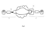
Figure 2 , in which the output of thetransmitter 1 is connected to anoptical coupler 13 making it possible to split the signal, and wherein aswitch 15 makes it possible to select the working path or protection path. Nonetheless, if signals are detected using a coherent receiver, the signals associated with that technique are retrieved as described inFigure 3 , in which the transmitted signal is mixed with a signal of alocal oscillator 17 by acoherent mixer 19 so as to retrieve different components of the mixed signal, these components being transmitted to asampler 21 and then to a digitalsignal processing device 23 in order to decode the information contained by the transmitted signal based on the retrieved components. However, this retrieval technique requires alocal oscillator 17 producing a signal of approximately the same wavelength as the transmitted signal. Thus, switching the working path over to the protection path (which may correspond to a different wavelength) requires knowing the wavelength of the protection signal (generally predefined by the network's control plane) and tuning the local oscillator to the newly received wavelength. Thus, the time taken to set up the protection connection (if an incident occurs on the working connection) includes the time taken by the control plane to react, the sending of a command to thelocal oscillator 17 by the control plane, and the tuning of thelocal oscillator 17. This time is non-negligible, and leads to a significant loss of information whenever the bitrate is high. - The goal of the present invention is therefore to overcome the aforementioned drawbacks of the state of the art and to disclose a method for reducing the time taken to adapt the receiver when the wavelength of the transmitted signal varies, such as when a protection connection is set up.
- Thus, the present invention discloses a method for homodyne reception, wherein a coherent mixer combines the transmitted optical signal with a baseline optical signal delivered by a local oscillator whose wavelength is within a predefined interval around the wavelength of the transmitted optical signal in order to produce interference signals corresponding to a beat between the transmitted optical signal and the baseline signal and intended to be detected by photodiodes, wherein said local oscillator comprises a Fabry-Pbrot laser cavity comprising a photorefractive holographic medium, said laser cavity being supplied by the transmitted optical signal whenever its wavelength varies so as to produce a baseline signal.
- According to another aspect of the present invention, the photorefractive holographic medium is a crystal of cadmium telluride (CdTe).
- According to an additional aspect of the present invention, the polarization state of the optical signal delivered by the local oscillator and transmitted to the coherent mixer is aligned with a predetermined polarization state.
- According to an additional aspect of the present invention, analog-digital converters sample the detected signals and a digital signal processing device processes the sampled signals in order to demodulate a data signal.
- According to another aspect of the present invention, the transmitted optical signal is polarization division multiplexed.
- The invention also pertains to a method for protecting an optical communication network whose connections between a transmitter and receiver comprise an active optical path and a protection optical path, wherein the receipt of a signal within the receiver is carried out according to the previously described method for receiving a signal, and wherein the receiver's input switches to the optical protection path whenever an incident occurs on the active optical path.
- According to another aspect of the present invention, the switchover is done by a switch.
- According to an additional aspect of the present invention, the active optical path signals have different wavelengths within said receiver.
- According to an additional aspect of the present invention, the signals of the active optical paths and optical protection paths are transmitted, at the transmitter's output, by an optical coupler to respective optical paths.
- The present invention also pertains to a device for retrieving a transmitted optical signal, comprising:
- a local oscillator intended to produce a baseline optical signal,
- a coherent mixer comprising two inputs intended to receive both the transmitted optical signal and the baseline signal, and outputs intended to transmit components of the mixed signal,
- a sampler comprising photodiodes and analog-digital converters,
- a digital signal processing module,
- The invention further comprises an optical node of a protection optical device, said protection device comprising an active optical path and a protection optical path, said optical paths connecting an optical emitter and an optical receiver, said optical node comprising:
- means for switching the active optical path over to the protection optical path in the event of an incident on the active optical path.
- demodulation means comprising:
- a local oscillator intended to produce a baseline optical signal,
- a coherent mixer comprising two inputs intended to receive both the signal transmitted by one of the optical paths and the baseline signal, and outputs intended to transmit components of the mixed signal,
- a sampler comprising photodiodes and analog-digital converters,
- a digital signal processing module,
- Other characteristics and benefits of the invention will become apparent from the following description, given with reference to the attached drawings, which by way of a non-limiting example depict one possible embodiment.
- In these drawings:
-
Figure 1 depicts an electrical protection diagram; -
Figure 2 depicts an optical protection diagram; -
Figure 3 depicts a diagram of a signal-retrieval device comprising a coherent demodulation according to the state of the art; -
Figure 4 depicts a diagram of a signal-retrieval device comprising a coherent demodulation according to the present invention; -
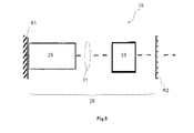
Figure 5 depicts a diagram of a laser cavity of a slave laser according to the present invention; - The embodiments of the present invention pertain to a method for receiving and retrieving a signal, said method being adapted to coherent detection and using a slave laser in order to produce the baseline signal needed for retrieval.
-
Figure 4 depicts a diagram of an optical receiver in accordance with the present invention. - The transmitted signal is sent to an
optical coupler 13 in order to split the signal and to transmit part of the signal to aslave laser 25 by means of anoptical circulator 27, and to transmit the other part of the signal directly to the first input of acoherent mixer 19. - The role of the
slave laser 25 is to produce a continuous signal at the same frequency as the transmitted optical signal. - One example embodiment of the slave laser is described in
Figure 5 . - The
slave laser 25 comprises acavity 26 bounded by two mirrors R1 and R2, one of which is a semi-reflective mirror R2, thereby forming a Fabry-Pbrot cavity 26. Thecavity 26 comprises anamplifying medium 29, acollimating lens 31, and a photorefractiveholographic medium 31. - This photorefractive
holographic medium 31 may, for example, be a crystal of cadmium telluride (CdTe) forcing the laser to carry out single-mode wavelength oscillation over its entire range of operation. The structure of stationary waves associated with each of the longitudinal modes records an index hologram within the crystal. The writing of an index grating occurs after the electrical charges available within the crystal have moved. As the number of charges is fixed, a phenomenon whereby the gratings between them are erased and strengthened occurs as a result. This self-organization process, combined with the competition phenomena that take place within the amplifyingmedium 29, under some conditions lead to thelaser 25 performing single-mode oscillation. - Additionally, injecting part of the transmitted signal into the
cavity 26 causes the crystal's index grating to adapt, and thus thelaser cavity 26 then emits around the wavelength imposed by the transmitted signal, even when the signal injection stops. - Thus, the
slave laser 25 emits an optical signal whose wavelength approximately corresponds to the wavelength of the transmitted signal. - The wavelength of the baseline signal does not need to be strictly identical to the wavelength of the transmitted signal, but rather may be within a relatively close interval, so as to produce, by signal interference, a beat between the two signals, and thereby to generate a base-band signal which is then detected by the photodiodes. The width of the wavelength's interval is defined by the technical characteristics of the
slave laser 25. This signal emitted by theslave laser 25 may then be used as a baseline for retrieving the signal comprising a coherent detection. To do so, the slave laser'soptical signal 25 is transmitted on the second input of thecoherent mixer 19 by means of theoptical circulator 27. - Furthermore, the polarization of the signal emitted by the
slave laser 25 and transmitted to thecoherent mixer 19 must be known when the signal penetrates into the coherent mixer, in order to enable the retrieval of the transmitted signal. Thus, the polarization state of the optical signal derived from the slave laser is aligned with a predetermined polarization state. - The
coherent mixer 19 generates components of the mixed signal resulting from interference between the baseline signal and the transmitted signal. - Different embodiments exist depending on the signals' mode of polarization and the coherent detection system used.
- According to one preferential mode, the signals are modulated using quadrature phase shift keying (QPSK), with the signals being detected on two polarizations and the non-alignment of the polarization axes being corrected numerically so that four photodiodes and four analog-digital converters are necessary.
- Nonetheless, other modulation formats may be used.
- Additionally, the alignment of the polarization axes may be done mechanically. In this situation, detection may be carried out on a single polarization, and two photodiodes as well as two analog-digital converters are sufficient.
- Furthermore, the
slave laser 25 requires that the control signal (i.e. the transmitted signal, in our situation) arrives with a certain power level within the laser cavity's 26 preferential polarization state. Thus, according to one embodiment of the present invention, the transmitted signals are polarization division multiplexed (PDM), which makes it possible to prevent the control signal of theslave laser 25 from arriving with a polarization orthogonal to theslave laser 25 cavity's 26 preferential polarization state. The components of the mixed signal are then sent to thesampler 21. - Within the
sampler 21, the signals are detected by photodiodes. In quadrature phase shift keying, four photodiodes deliver four quadrature phase-shifted electrical signals. The electrical signals are then sampled by analog-digital converters and transmitted to a digitalsignal processing device 23. - Thus, unlike the
tunable laser 17 used in the state of the art requiring a command from the control plane and a certain length of time to tune when the receiver is switching a signal at a certain wavelength to another signal at a different wavelength, the slave laser makes it possible to automatically and quickly tune to the protection signal's wavelength, and thereby makes it possible to reduce the time needed to implement the protection connection. Additionally, implementing the present invention's embodiments has a limited cost, because the changes compared to a signal-retrieving device comprising coherent demodulation according to the state of the art only involve replacing the tunable laser 17 (corresponding to the local oscillator) with aslave laser 25, and using anoptical coupler 13 and anoptical circulator 27 so as to transmit part of the transmitted signal to theslave laser 25, then to transmit the baseline signal derived from theslave laser 25 to thecoherent mixer 19. - Owing to the use of a
slave laser 25, the embodiments of the present invention make it possible to reduce the time needed to adapt the signal-retrieving circuit comprising a coherent detection whenever the wavelength of the transmitted signal changes, and consequently make it possible to use an optical protection scheme while also using coherent detection. The present invention therefore makes it possible to limit the quantity of signals lost in the event of an incident on an active connection, and to limit the cost needed to implement effective protection.
Claims (10)
- A method for homodyne reception, wherein a coherent mixer (19) combines the transmitted optical signal with a baseline optical signal delivered by a local oscillator (25) whose wavelength is within a predefined interval around the wavelength of the transmitted optical signal in order to produce interference signals corresponding to a beat between the transmitted optical signal and the baseline signal and intended to be detected by photodiodes, wherein said local oscillator (17, 25) comprises a Fabry-Pbrot laser cavity (26) comprising a photorefractive holographic medium (33), said laser cavity being supplied by the transmitted optical signal whenever its wavelength varies so as to produce a baseline signal.
- A method for receiving a signal according to claim 1, wherein the photorefractive holographic medium (26) is a crystal of cadmium telluride (CdTe).
- A method for receiving a signal according to one of the preceding claims, wherein the polarization state of the optical signal delivered by the local oscillator (25) and transmitted to the coherent mixer (19) is aligned with a predetermined polarization state.
- A method for receiving a signal according to one of the preceding claims, wherein analog-digital converters sample the detected signals and a digital signal processing device processes the sampled signals in order to demodulate a data signal.
- A method for receiving a signal according to one of the preceding claims, wherein the transmitted optical signal is polarization division multiplexed.
- A method for protecting an optical communication network whose connections between a transmitter (1) and a receiver (5) comprise an active optical path and a protection optical path, wherein the receipt of a signal within the receiver (5) is carried out according to one of the claims 1 to 5 and wherein the receiver's (5) input switches to the optical protection path whenever an incident occurs on the active optical path.
- A protection method according to claim 6, wherein the switchover is carried out by a switch (15).
- A protection method according to claim 6 or 7, wherein the active optical path signals have different wavelengths within said receiver (5).
- An device for retrieving a transmitted optical signal comprising:- a local oscillator (17, 25) intended to produce a baseline optical signal,- a coherent mixer (19) comprising two inputs intended to receive both the transmitted optical signal and the baseline signal, and outputs intended to transmit components of the mixed signal,- a sampler (21) comprising photodiodes and analog-digital converters,- a digital signal processing module (23),wherein said local oscillator (17, 25) comprises a Fabry-Pérot laser cavity (26) comprising a photorefractive holographic medium (33), said laser cavity (26) being supplied by the transmitted optical signal whenever its wavelength varies so as to produce a baseline signal whose wavelength is within a predefined interval around the wavelength of the transmitted signal so as to produce a beat between the transmitted signal and the baseline signal within the coherent mixer (19).
- An optical node of an optical protection device, said protection device comprising an active optical path and a protection optical path, said optical paths connecting an optical emitter and an optical receiver, said optical node comprising:- means for switching (15) the active optical path over to the protection optical path in the event of an incident on the active optical path,- demodulation means comprising:- a local oscillator (17, 25) intended to produce a baseline optical signal,- a coherent mixer (19) comprising two inputs intended to receive both the signal transmitted by one of the optical paths and the baseline signal, and outputs intended to transmit components of the mixed signal,- a sampler (21) comprising photodiodes and analog-digital converters,- a digital signal processing module (23),wherein the local oscillator (17, 25) comprises a Fabry-Pérot laser cavity (26) comprising a photorefractive holographic medium (33) and supplied by the signal transmitted by one of the optical paths, said oscillator (19) being configured to transmit a baseline signal whose wavelength is within a predefined interval around the wavelength of the signal supplying said local oscillator (19) so as to produce a beat between the two signals within the coherent mixer (19).
Applications Claiming Priority (1)
| Application Number | Priority Date | Filing Date | Title |
|---|---|---|---|
| FR0906197A FR2954637B1 (en) | 2009-12-21 | 2009-12-21 | METHOD FOR RECEIVING A SIGNAL |
Publications (2)
| Publication Number | Publication Date |
|---|---|
| EP2337244A1 true EP2337244A1 (en) | 2011-06-22 |
| EP2337244B1 EP2337244B1 (en) | 2016-09-28 |
Family
ID=42340712
Family Applications (1)
| Application Number | Title | Priority Date | Filing Date |
|---|---|---|---|
| EP10193549.2A Not-in-force EP2337244B1 (en) | 2009-12-21 | 2010-12-02 | Method and device for homodyne reception of an optical signal |
Country Status (2)
| Country | Link |
|---|---|
| EP (1) | EP2337244B1 (en) |
| FR (1) | FR2954637B1 (en) |
Cited By (2)
| Publication number | Priority date | Publication date | Assignee | Title |
|---|---|---|---|---|
| CN105896309A (en) * | 2016-06-13 | 2016-08-24 | 深圳新飞通光电子技术有限公司 | Bidirectional output DFB tunable laser module and coherent light transmission system thereof |
| CN115266582A (en) * | 2022-06-30 | 2022-11-01 | 山东大学 | Fabry-Perot resonant cavity type salinity sensor |
Citations (2)
| Publication number | Priority date | Publication date | Assignee | Title |
|---|---|---|---|---|
| EP1125347B1 (en) * | 1998-10-28 | 2003-01-29 | Centre National De La Recherche Scientifique | Self-adapted filters for sharpening laser emission |
| US20060245766A1 (en) * | 2005-04-29 | 2006-11-02 | Taylor Michael G | Phase estimation for coherent optical detection |
-
2009
- 2009-12-21 FR FR0906197A patent/FR2954637B1/en not_active Expired - Fee Related
-
2010
- 2010-12-02 EP EP10193549.2A patent/EP2337244B1/en not_active Not-in-force
Patent Citations (2)
| Publication number | Priority date | Publication date | Assignee | Title |
|---|---|---|---|---|
| EP1125347B1 (en) * | 1998-10-28 | 2003-01-29 | Centre National De La Recherche Scientifique | Self-adapted filters for sharpening laser emission |
| US20060245766A1 (en) * | 2005-04-29 | 2006-11-02 | Taylor Michael G | Phase estimation for coherent optical detection |
Non-Patent Citations (2)
| Title |
|---|
| DUBREUIL N ET AL: "TUNABLE SELF-ADAPTIVE CAVITY LASER DIODE WITH WAVELENGTH ALL-OPTICAL ADDRESSING", PROCEEDINGS OF THE EUROPEAN CONFERENCE ON OPTICALCOMMUNICATION, XX, XX, vol. 3, 1 January 2004 (2004-01-01), pages 600/601, XP009060284 * |
| TSUKAMOTO S ET AL: "Coherent demodulation of 40-Gbit/s polarization-multiplexed QPSK signals with 16-GHz spacing after 200-km transmission", 2005 OPTICAL FIBER COMMUNICATIONS CONFERENCE TECHNICAL DIGEST (IEEE CAT. NO. 05CH37672) IEEE PISCATAWAY, NJ, USA,, vol. 6, 6 March 2005 (2005-03-06), pages 85 - 87, XP010833521, ISBN: 978-1-55752-783-7 * |
Cited By (2)
| Publication number | Priority date | Publication date | Assignee | Title |
|---|---|---|---|---|
| CN105896309A (en) * | 2016-06-13 | 2016-08-24 | 深圳新飞通光电子技术有限公司 | Bidirectional output DFB tunable laser module and coherent light transmission system thereof |
| CN115266582A (en) * | 2022-06-30 | 2022-11-01 | 山东大学 | Fabry-Perot resonant cavity type salinity sensor |
Also Published As
| Publication number | Publication date |
|---|---|
| EP2337244B1 (en) | 2016-09-28 |
| FR2954637A1 (en) | 2011-06-24 |
| FR2954637B1 (en) | 2014-07-18 |
Similar Documents
| Publication | Publication Date | Title |
|---|---|---|
| EP0981869B1 (en) | Modulation format adjusting optical transponders | |
| US5173794A (en) | Wavelength division multiplexing using a tunable acousto-optic filter | |
| US9407426B2 (en) | Optical network interface, module and engine | |
| US8009989B1 (en) | Integrated electro-optic hybrid communication system | |
| US8958706B2 (en) | Coherent optical communication device and method | |
| EP1330054A2 (en) | System and method for multi-level phase modulated communication | |
| JPH04233339A (en) | Radio communication system, particularly cell-shaped vehicle wireless system | |
| US11119003B2 (en) | Calibration apparatus and method, and wavelength division multiplexing system | |
| US10056979B2 (en) | Optical transmission device and optical communication system | |
| EP3349375B1 (en) | A method and apparatus for automatic compensation of chromatic dispersion | |
| CN115225152B (en) | Optical network detection method, optical transceiver component, and optical network equipment | |
| EP2343840A1 (en) | Method, device and optical node for coherent reception of an optical signal | |
| EP3783816B1 (en) | Optical signal transceiving device | |
| EP2337244B1 (en) | Method and device for homodyne reception of an optical signal | |
| US7769299B2 (en) | Chromatic dispersion monitoring method and chromatic dispersion monitoring apparatus, and optical transmission system | |
| US20040208569A1 (en) | System adopting wavelength division multiplexing and method of operating the system | |
| WO2017002322A1 (en) | Communication device, communication method, and communication system | |
| JPH10126341A (en) | Optical transmitter and optical network system | |
| US6751375B1 (en) | Self-referencing tunable add-drop filters | |
| NO171819B (en) | PROCEDURE FOR OPTICAL TELECOMMUNICATION TRANSFER | |
| US6795610B1 (en) | Tunable add-drop filters using two independent optical paths | |
| US12531639B2 (en) | Optical transmission control device | |
| US6826326B1 (en) | Quasi-hitless tunable add-drop filters | |
| JP5871642B2 (en) | Coherent transmission system and method | |
| KR102016928B1 (en) | Method and Apparatus for Synchronizing using Opto-electronic Oscillator |
Legal Events
| Date | Code | Title | Description |
|---|---|---|---|
| PUAI | Public reference made under article 153(3) epc to a published international application that has entered the european phase |
Free format text: ORIGINAL CODE: 0009012 |
|
| AK | Designated contracting states |
Kind code of ref document: A1 Designated state(s): AL AT BE BG CH CY CZ DE DK EE ES FI FR GB GR HR HU IE IS IT LI LT LU LV MC MK MT NL NO PL PT RO RS SE SI SK SM TR |
|
| AX | Request for extension of the european patent |
Extension state: BA ME |
|
| 17P | Request for examination filed |
Effective date: 20111222 |
|
| 111Z | Information provided on other rights and legal means of execution |
Free format text: AL AT BE BG CH CY CZ DE DK EE ES FI FR GB GR HR HU IE IS IT LI LT LU LV MC MK MT NL NO PL PT RO RS SE SI SK SM TR Effective date: 20130410 |
|
| RAP1 | Party data changed (applicant data changed or rights of an application transferred) |
Owner name: ALCATEL LUCENT |
|
| D11X | Information provided on other rights and legal means of execution (deleted) | ||
| REG | Reference to a national code |
Ref country code: DE Ref legal event code: R079 Ref document number: 602010036720 Country of ref document: DE Free format text: PREVIOUS MAIN CLASS: H04B0010148000 Ipc: H01S0003106000 |
|
| GRAP | Despatch of communication of intention to grant a patent |
Free format text: ORIGINAL CODE: EPIDOSNIGR1 |
|
| RIC1 | Information provided on ipc code assigned before grant |
Ipc: H04B 10/60 20130101ALI20160407BHEP Ipc: H01S 5/14 20060101ALI20160407BHEP Ipc: H01S 3/106 20060101AFI20160407BHEP Ipc: H04B 10/63 20130101ALI20160407BHEP Ipc: H01S 3/08 20060101ALI20160407BHEP |
|
| INTG | Intention to grant announced |
Effective date: 20160504 |
|
| GRAS | Grant fee paid |
Free format text: ORIGINAL CODE: EPIDOSNIGR3 |
|
| GRAA | (expected) grant |
Free format text: ORIGINAL CODE: 0009210 |
|
| AK | Designated contracting states |
Kind code of ref document: B1 Designated state(s): AL AT BE BG CH CY CZ DE DK EE ES FI FR GB GR HR HU IE IS IT LI LT LU LV MC MK MT NL NO PL PT RO RS SE SI SK SM TR |
|
| REG | Reference to a national code |
Ref country code: GB Ref legal event code: FG4D |
|
| REG | Reference to a national code |
Ref country code: CH Ref legal event code: EP |
|
| REG | Reference to a national code |
Ref country code: AT Ref legal event code: REF Ref document number: 833469 Country of ref document: AT Kind code of ref document: T Effective date: 20161015 |
|
| REG | Reference to a national code |
Ref country code: IE Ref legal event code: FG4D |
|
| REG | Reference to a national code |
Ref country code: DE Ref legal event code: R096 Ref document number: 602010036720 Country of ref document: DE |
|
| REG | Reference to a national code |
Ref country code: FR Ref legal event code: PLFP Year of fee payment: 7 |
|
| REG | Reference to a national code |
Ref country code: LT Ref legal event code: MG4D |
|
| PG25 | Lapsed in a contracting state [announced via postgrant information from national office to epo] |
Ref country code: NO Free format text: LAPSE BECAUSE OF FAILURE TO SUBMIT A TRANSLATION OF THE DESCRIPTION OR TO PAY THE FEE WITHIN THE PRESCRIBED TIME-LIMIT Effective date: 20161228 Ref country code: FI Free format text: LAPSE BECAUSE OF FAILURE TO SUBMIT A TRANSLATION OF THE DESCRIPTION OR TO PAY THE FEE WITHIN THE PRESCRIBED TIME-LIMIT Effective date: 20160928 Ref country code: LT Free format text: LAPSE BECAUSE OF FAILURE TO SUBMIT A TRANSLATION OF THE DESCRIPTION OR TO PAY THE FEE WITHIN THE PRESCRIBED TIME-LIMIT Effective date: 20160928 Ref country code: RS Free format text: LAPSE BECAUSE OF FAILURE TO SUBMIT A TRANSLATION OF THE DESCRIPTION OR TO PAY THE FEE WITHIN THE PRESCRIBED TIME-LIMIT Effective date: 20160928 Ref country code: HR Free format text: LAPSE BECAUSE OF FAILURE TO SUBMIT A TRANSLATION OF THE DESCRIPTION OR TO PAY THE FEE WITHIN THE PRESCRIBED TIME-LIMIT Effective date: 20160928 |
|
| REG | Reference to a national code |
Ref country code: NL Ref legal event code: MP Effective date: 20160928 |
|
| REG | Reference to a national code |
Ref country code: AT Ref legal event code: MK05 Ref document number: 833469 Country of ref document: AT Kind code of ref document: T Effective date: 20160928 |
|
| PG25 | Lapsed in a contracting state [announced via postgrant information from national office to epo] |
Ref country code: LV Free format text: LAPSE BECAUSE OF FAILURE TO SUBMIT A TRANSLATION OF THE DESCRIPTION OR TO PAY THE FEE WITHIN THE PRESCRIBED TIME-LIMIT Effective date: 20160928 Ref country code: GR Free format text: LAPSE BECAUSE OF FAILURE TO SUBMIT A TRANSLATION OF THE DESCRIPTION OR TO PAY THE FEE WITHIN THE PRESCRIBED TIME-LIMIT Effective date: 20161229 Ref country code: SE Free format text: LAPSE BECAUSE OF FAILURE TO SUBMIT A TRANSLATION OF THE DESCRIPTION OR TO PAY THE FEE WITHIN THE PRESCRIBED TIME-LIMIT Effective date: 20160928 Ref country code: NL Free format text: LAPSE BECAUSE OF FAILURE TO SUBMIT A TRANSLATION OF THE DESCRIPTION OR TO PAY THE FEE WITHIN THE PRESCRIBED TIME-LIMIT Effective date: 20160928 |
|
| PGFP | Annual fee paid to national office [announced via postgrant information from national office to epo] |
Ref country code: FR Payment date: 20161222 Year of fee payment: 7 |
|
| PG25 | Lapsed in a contracting state [announced via postgrant information from national office to epo] |
Ref country code: EE Free format text: LAPSE BECAUSE OF FAILURE TO SUBMIT A TRANSLATION OF THE DESCRIPTION OR TO PAY THE FEE WITHIN THE PRESCRIBED TIME-LIMIT Effective date: 20160928 Ref country code: RO Free format text: LAPSE BECAUSE OF FAILURE TO SUBMIT A TRANSLATION OF THE DESCRIPTION OR TO PAY THE FEE WITHIN THE PRESCRIBED TIME-LIMIT Effective date: 20160928 |
|
| PG25 | Lapsed in a contracting state [announced via postgrant information from national office to epo] |
Ref country code: CZ Free format text: LAPSE BECAUSE OF FAILURE TO SUBMIT A TRANSLATION OF THE DESCRIPTION OR TO PAY THE FEE WITHIN THE PRESCRIBED TIME-LIMIT Effective date: 20160928 Ref country code: SK Free format text: LAPSE BECAUSE OF FAILURE TO SUBMIT A TRANSLATION OF THE DESCRIPTION OR TO PAY THE FEE WITHIN THE PRESCRIBED TIME-LIMIT Effective date: 20160928 Ref country code: BG Free format text: LAPSE BECAUSE OF FAILURE TO SUBMIT A TRANSLATION OF THE DESCRIPTION OR TO PAY THE FEE WITHIN THE PRESCRIBED TIME-LIMIT Effective date: 20161228 Ref country code: AT Free format text: LAPSE BECAUSE OF FAILURE TO SUBMIT A TRANSLATION OF THE DESCRIPTION OR TO PAY THE FEE WITHIN THE PRESCRIBED TIME-LIMIT Effective date: 20160928 Ref country code: PT Free format text: LAPSE BECAUSE OF FAILURE TO SUBMIT A TRANSLATION OF THE DESCRIPTION OR TO PAY THE FEE WITHIN THE PRESCRIBED TIME-LIMIT Effective date: 20170130 Ref country code: ES Free format text: LAPSE BECAUSE OF FAILURE TO SUBMIT A TRANSLATION OF THE DESCRIPTION OR TO PAY THE FEE WITHIN THE PRESCRIBED TIME-LIMIT Effective date: 20160928 Ref country code: SM Free format text: LAPSE BECAUSE OF FAILURE TO SUBMIT A TRANSLATION OF THE DESCRIPTION OR TO PAY THE FEE WITHIN THE PRESCRIBED TIME-LIMIT Effective date: 20160928 Ref country code: BE Free format text: LAPSE BECAUSE OF FAILURE TO SUBMIT A TRANSLATION OF THE DESCRIPTION OR TO PAY THE FEE WITHIN THE PRESCRIBED TIME-LIMIT Effective date: 20160928 Ref country code: PL Free format text: LAPSE BECAUSE OF FAILURE TO SUBMIT A TRANSLATION OF THE DESCRIPTION OR TO PAY THE FEE WITHIN THE PRESCRIBED TIME-LIMIT Effective date: 20160928 Ref country code: IS Free format text: LAPSE BECAUSE OF FAILURE TO SUBMIT A TRANSLATION OF THE DESCRIPTION OR TO PAY THE FEE WITHIN THE PRESCRIBED TIME-LIMIT Effective date: 20170128 |
|
| REG | Reference to a national code |
Ref country code: DE Ref legal event code: R097 Ref document number: 602010036720 Country of ref document: DE |
|
| PG25 | Lapsed in a contracting state [announced via postgrant information from national office to epo] |
Ref country code: IT Free format text: LAPSE BECAUSE OF FAILURE TO SUBMIT A TRANSLATION OF THE DESCRIPTION OR TO PAY THE FEE WITHIN THE PRESCRIBED TIME-LIMIT Effective date: 20160928 |
|
| PG25 | Lapsed in a contracting state [announced via postgrant information from national office to epo] |
Ref country code: DK Free format text: LAPSE BECAUSE OF FAILURE TO SUBMIT A TRANSLATION OF THE DESCRIPTION OR TO PAY THE FEE WITHIN THE PRESCRIBED TIME-LIMIT Effective date: 20160928 |
|
| REG | Reference to a national code |
Ref country code: CH Ref legal event code: PL |
|
| PLBE | No opposition filed within time limit |
Free format text: ORIGINAL CODE: 0009261 |
|
| STAA | Information on the status of an ep patent application or granted ep patent |
Free format text: STATUS: NO OPPOSITION FILED WITHIN TIME LIMIT |
|
| 26N | No opposition filed |
Effective date: 20170629 |
|
| PG25 | Lapsed in a contracting state [announced via postgrant information from national office to epo] |
Ref country code: MC Free format text: LAPSE BECAUSE OF FAILURE TO SUBMIT A TRANSLATION OF THE DESCRIPTION OR TO PAY THE FEE WITHIN THE PRESCRIBED TIME-LIMIT Effective date: 20160928 |
|
| REG | Reference to a national code |
Ref country code: IE Ref legal event code: MM4A |
|
| PG25 | Lapsed in a contracting state [announced via postgrant information from national office to epo] |
Ref country code: CH Free format text: LAPSE BECAUSE OF NON-PAYMENT OF DUE FEES Effective date: 20161231 Ref country code: LU Free format text: LAPSE BECAUSE OF NON-PAYMENT OF DUE FEES Effective date: 20161202 Ref country code: LI Free format text: LAPSE BECAUSE OF NON-PAYMENT OF DUE FEES Effective date: 20161231 |
|
| PG25 | Lapsed in a contracting state [announced via postgrant information from national office to epo] |
Ref country code: IE Free format text: LAPSE BECAUSE OF NON-PAYMENT OF DUE FEES Effective date: 20161202 Ref country code: SI Free format text: LAPSE BECAUSE OF FAILURE TO SUBMIT A TRANSLATION OF THE DESCRIPTION OR TO PAY THE FEE WITHIN THE PRESCRIBED TIME-LIMIT Effective date: 20160928 |
|
| PGFP | Annual fee paid to national office [announced via postgrant information from national office to epo] |
Ref country code: DE Payment date: 20171211 Year of fee payment: 8 |
|
| PGFP | Annual fee paid to national office [announced via postgrant information from national office to epo] |
Ref country code: GB Payment date: 20171221 Year of fee payment: 8 |
|
| PG25 | Lapsed in a contracting state [announced via postgrant information from national office to epo] |
Ref country code: CY Free format text: LAPSE BECAUSE OF FAILURE TO SUBMIT A TRANSLATION OF THE DESCRIPTION OR TO PAY THE FEE WITHIN THE PRESCRIBED TIME-LIMIT Effective date: 20160928 Ref country code: HU Free format text: LAPSE BECAUSE OF FAILURE TO SUBMIT A TRANSLATION OF THE DESCRIPTION OR TO PAY THE FEE WITHIN THE PRESCRIBED TIME-LIMIT; INVALID AB INITIO Effective date: 20101202 |
|
| PG25 | Lapsed in a contracting state [announced via postgrant information from national office to epo] |
Ref country code: TR Free format text: LAPSE BECAUSE OF FAILURE TO SUBMIT A TRANSLATION OF THE DESCRIPTION OR TO PAY THE FEE WITHIN THE PRESCRIBED TIME-LIMIT Effective date: 20160928 Ref country code: MK Free format text: LAPSE BECAUSE OF FAILURE TO SUBMIT A TRANSLATION OF THE DESCRIPTION OR TO PAY THE FEE WITHIN THE PRESCRIBED TIME-LIMIT Effective date: 20160928 |
|
| PG25 | Lapsed in a contracting state [announced via postgrant information from national office to epo] |
Ref country code: MT Free format text: LAPSE BECAUSE OF NON-PAYMENT OF DUE FEES Effective date: 20161202 |
|
| REG | Reference to a national code |
Ref country code: FR Ref legal event code: ST Effective date: 20180831 |
|
| PG25 | Lapsed in a contracting state [announced via postgrant information from national office to epo] |
Ref country code: AL Free format text: LAPSE BECAUSE OF FAILURE TO SUBMIT A TRANSLATION OF THE DESCRIPTION OR TO PAY THE FEE WITHIN THE PRESCRIBED TIME-LIMIT Effective date: 20160928 Ref country code: FR Free format text: LAPSE BECAUSE OF NON-PAYMENT OF DUE FEES Effective date: 20180102 |
|
| REG | Reference to a national code |
Ref country code: DE Ref legal event code: R082 Ref document number: 602010036720 Country of ref document: DE Representative=s name: MENZIETTI WETZEL, DE Ref country code: DE Ref legal event code: R081 Ref document number: 602010036720 Country of ref document: DE Owner name: PROVENANCE ASSET GROUP LLC, PITTSFORD, US Free format text: FORMER OWNER: ALCATEL LUCENT, BOULOGNE BILLANCOURT, FR |
|
| REG | Reference to a national code |
Ref country code: GB Ref legal event code: 732E Free format text: REGISTERED BETWEEN 20190418 AND 20190426 |
|
| REG | Reference to a national code |
Ref country code: DE Ref legal event code: R119 Ref document number: 602010036720 Country of ref document: DE |
|
| GBPC | Gb: european patent ceased through non-payment of renewal fee |
Effective date: 20181202 |
|
| PG25 | Lapsed in a contracting state [announced via postgrant information from national office to epo] |
Ref country code: DE Free format text: LAPSE BECAUSE OF NON-PAYMENT OF DUE FEES Effective date: 20190702 |
|
| PG25 | Lapsed in a contracting state [announced via postgrant information from national office to epo] |
Ref country code: GB Free format text: LAPSE BECAUSE OF NON-PAYMENT OF DUE FEES Effective date: 20181202 |