EP2337189A2 - Generator packaging arrangement - Google Patents
Generator packaging arrangement Download PDFInfo
- Publication number
- EP2337189A2 EP2337189A2 EP10196060A EP10196060A EP2337189A2 EP 2337189 A2 EP2337189 A2 EP 2337189A2 EP 10196060 A EP10196060 A EP 10196060A EP 10196060 A EP10196060 A EP 10196060A EP 2337189 A2 EP2337189 A2 EP 2337189A2
- Authority
- EP
- European Patent Office
- Prior art keywords
- generator
- disconnect
- shaft
- drive gear
- main
- Prior art date
- Legal status (The legal status is an assumption and is not a legal conclusion. Google has not performed a legal analysis and makes no representation as to the accuracy of the status listed.)
- Granted
Links
Images


Classifications
-
- H—ELECTRICITY
- H02—GENERATION; CONVERSION OR DISTRIBUTION OF ELECTRIC POWER
- H02K—DYNAMO-ELECTRIC MACHINES
- H02K7/00—Arrangements for handling mechanical energy structurally associated with dynamo-electric machines, e.g. structural association with mechanical driving motors or auxiliary dynamo-electric machines
- H02K7/10—Structural association with clutches, brakes, gears, pulleys or mechanical starters
- H02K7/116—Structural association with clutches, brakes, gears, pulleys or mechanical starters with gears
-
- H—ELECTRICITY
- H02—GENERATION; CONVERSION OR DISTRIBUTION OF ELECTRIC POWER
- H02K—DYNAMO-ELECTRIC MACHINES
- H02K7/00—Arrangements for handling mechanical energy structurally associated with dynamo-electric machines, e.g. structural association with mechanical driving motors or auxiliary dynamo-electric machines
- H02K7/10—Structural association with clutches, brakes, gears, pulleys or mechanical starters
- H02K7/102—Structural association with clutches, brakes, gears, pulleys or mechanical starters with friction brakes
-
- H—ELECTRICITY
- H02—GENERATION; CONVERSION OR DISTRIBUTION OF ELECTRIC POWER
- H02K—DYNAMO-ELECTRIC MACHINES
- H02K7/00—Arrangements for handling mechanical energy structurally associated with dynamo-electric machines, e.g. structural association with mechanical driving motors or auxiliary dynamo-electric machines
- H02K7/10—Structural association with clutches, brakes, gears, pulleys or mechanical starters
- H02K7/108—Structural association with clutches, brakes, gears, pulleys or mechanical starters with friction clutches
-
- H—ELECTRICITY
- H02—GENERATION; CONVERSION OR DISTRIBUTION OF ELECTRIC POWER
- H02K—DYNAMO-ELECTRIC MACHINES
- H02K7/00—Arrangements for handling mechanical energy structurally associated with dynamo-electric machines, e.g. structural association with mechanical driving motors or auxiliary dynamo-electric machines
- H02K7/18—Structural association of electric generators with mechanical driving motors, e.g. with turbines
- H02K7/1807—Rotary generators
- H02K7/1823—Rotary generators structurally associated with turbines or similar engines
-
- H—ELECTRICITY
- H02—GENERATION; CONVERSION OR DISTRIBUTION OF ELECTRIC POWER
- H02K—DYNAMO-ELECTRIC MACHINES
- H02K2213/00—Specific aspects, not otherwise provided for and not covered by codes H02K2201/00 - H02K2211/00
- H02K2213/06—Machines characterised by the presence of fail safe, back up, redundant or other similar emergency arrangements
-
- H—ELECTRICITY
- H02—GENERATION; CONVERSION OR DISTRIBUTION OF ELECTRIC POWER
- H02K—DYNAMO-ELECTRIC MACHINES
- H02K7/00—Arrangements for handling mechanical energy structurally associated with dynamo-electric machines, e.g. structural association with mechanical driving motors or auxiliary dynamo-electric machines
- H02K7/20—Structural association with auxiliary dynamo-electric machines, e.g. with electric starter motors or exciters
-
- Y—GENERAL TAGGING OF NEW TECHNOLOGICAL DEVELOPMENTS; GENERAL TAGGING OF CROSS-SECTIONAL TECHNOLOGIES SPANNING OVER SEVERAL SECTIONS OF THE IPC; TECHNICAL SUBJECTS COVERED BY FORMER USPC CROSS-REFERENCE ART COLLECTIONS [XRACs] AND DIGESTS
- Y10—TECHNICAL SUBJECTS COVERED BY FORMER USPC
- Y10T—TECHNICAL SUBJECTS COVERED BY FORMER US CLASSIFICATION
- Y10T74/00—Machine element or mechanism
- Y10T74/19—Gearing
-
- Y—GENERAL TAGGING OF NEW TECHNOLOGICAL DEVELOPMENTS; GENERAL TAGGING OF CROSS-SECTIONAL TECHNOLOGIES SPANNING OVER SEVERAL SECTIONS OF THE IPC; TECHNICAL SUBJECTS COVERED BY FORMER USPC CROSS-REFERENCE ART COLLECTIONS [XRACs] AND DIGESTS
- Y10—TECHNICAL SUBJECTS COVERED BY FORMER USPC
- Y10T—TECHNICAL SUBJECTS COVERED BY FORMER US CLASSIFICATION
- Y10T74/00—Machine element or mechanism
- Y10T74/19—Gearing
- Y10T74/19642—Directly cooperating gears
Definitions
- the present disclosure relates to a generator packaging arrangement which facilitates heavier generator installation onto smaller gearboxes without adversely affecting the gearbox weight yet maintains desired generator design features.
- An accessory system includes a 4-Pole generator integrally mounted with an accessory gearbox such that a drive gear of the generator is in meshing engagement with the geartrain.
- a 4-Pole generator includes a generator housing which defines a flange.
- a drive shaft assembly is supported within the generator housing and a main generator power section is supported on the drive shaft assembly axially adjacent the flange.
- a generator includes a drive gear mounted to a main rotor shaft though a drive gear bearing and an input jaw plate keyed to the drive gear for rotation therewith, the input jaw plate defines input jaws which selectively mesh with the disconnect jaws, the disconnect shaft axially movable in response to a disconnect system which axially separates input jaws and the disconnect jaws to permit relative rotation between a main rotor shaft and the drive gear through the drive gear bearing.
- FIG 1 schematically illustrates a generator 20 which mounts to an aircraft accessory gearbox AG (illustrated schematically) though a drive gear 20G which rotates about a generator axis of rotation A to form an accessory gearbox system 10.
- the generator 20 may alternatively be a starter generator.
- the generator 20 includes a generator housing 20H which defines a mounting flange 20F that is axially outboard of the drive gear 20G relative to the accessory gearbox AG.
- the drive gear 20G extends through a side area of the generator housing 20H at a scallop 21 to mesh with the geartrain G within the accessory gearbox AG.
- the drive gear 20G is integral with the geartrain G of the accessory gearbox AG. That is, the drive gear 20G is part of the geartrain G such that gears downstream of the drive gear 20G are utilized to drive associated accessory systems.
- the generator 20 generally includes a main generator power section 22, an exciter 24, a rectifier assembly 26 and an optional permanent magnet generator (PMG) 28.
- the generator 20 provides a packaging arrangement in which the heaviest portions of the generator 20 such as the main generator power section 22 are located generally adjacent to the gearbox mounting flange 20F and at least partially within the accessory gearbox AG.
- a 4-Pole Integrally Mounted Gearbox Generator is illustrated. It should be appreciated that a 2-pole machine operates at a relatively higher speed and may have a relatively larger core than a 4-pole machine, however a 4-pole machine provides relatively greater rotor mechanical strength and may have relatively greater reliability. It should be appreciated that any pole count design generator may be integrated with an accessory gearbox AG as described herein.
- the main generator power section 22 provides alternating current (AC) power to an aircraft electrical bus (not shown).
- the exciter 24 provides excitation current to the field of the main generator power section 22.
- the rectifier assembly 26 provides conversion of exciter armature alternating current (AC) power into direct current (DC) power for the main field portion of the main generator power section 22. If generator self-excitation is required, the generator 20 will also include the PMG 28 which provides AC power to the generator control unit for generator field excitation power.
- the main generator power section 22, the exciter 24 and the optional PMG 28 are mounted on a common rotor shaft assembly 30 which is supported within the generator housing 20H of the generator 20 by main bearings 34A, 34B.
- the gearbox mounting flange 20F and the main generator power section 22 are axially located between the main bearings 34A, 34B, the exciter 24 is mounted on the rotor shaft assembly 30 axially outboard of the second main bearing 34B.
- the PMG 28 is axially outboard of the exciter 24, and exciter 24 is mounted opposite the accessory gearbox AG, i.e. the main field/stator is located between the exciter 24 and the drive gear 20G.
- the rotor shaft assembly 30 generally includes a main rotor shaft 36 and a disconnect shaft 38.
- Splines 36A are formed at an axially intermediate portion of an inner bore of the main rotor shaft 36 and mate with splines 38A on the disconnect shaft 38.
- the disconnect shaft 38 in the disclosed non-limiting embodiment includes a reduced diameter torsional section 38T and a shear section 38S.
- the torsional section 38T provides a relatively low torsional stiffness to minimize torque spike transmissibility.
- the shear section 38S is essentially a fuse which will break should excessive gear train torque loads occur.
- a disconnect system 42 provides the ability to mechanically disengage the generator 20 from the accessory gearbox AG should a generator failure occur.
- the disconnect system 42 includes disconnect jaws 38J adjacent to an end section of the disconnect shaft 38 which selectively mesh with input jaws 40J on an input jaw plate 40.
- a spring 41 biases the disconnect shaft 38 away from the main rotor shaft 36.
- the input jaw plate 40 is keyed to the drive gear 20G to transfer torque there between.
- the input jaw plate 40 permits selective relative rotation between the main rotor shaft 36 and the drive gear 20G when the disconnect jaw 38J is axially separated from the input jaw 40J in response to actuation of the disconnect system 42 as seen in Figure 3 when it is desired that there not be operation of the generator 20.
- the disconnect system 42 generally includes a plunger 44 which is selectively actuated by an electric/thermal solenoid 46. When actuated, the plunger 44 is moved into the position illustrated in Figure 3 , and rides along a ramp helix 48 of the disconnect shaft 38 to a lockout diameter 50 which maintains the disconnect jaw 38J axially separated from the input jaw plate 40. That is, engagement of the plunger 44 with the ramp helix 48 results in axial translation of the disconnect shaft 38 along the splined interface 36A-38A to separate the disconnect jaw 38J from the input jaw 40J which disconnects the drive gear 20G from the rotor shaft assembly 30.
- the lockout diameter is a distal end 38E of said disconnect shaft 38.
- the mechanical power transmitted into the rotor shaft assembly 30 ceases and the speed of the generator 20 coasts down to zero rpm through a drive gear bearing 52 packaged between the rotor drive gear 20G and the rotor shaft assembly 30.
- the drive gear bearing 52 is axially outboard of the main bearing 34A.
- the drive gear bearing 52 allows the drive gear 20G to continue rotation and thereby transmit power to any downstream systems. If a generator failure should occur, for example, the generator 20 may be disconnected from the accessory gearbox AG without effect to downstream systems which are in meshed engagement through the geartrain G. That is, the accessory gearbox AG can still drive the downstream system with the generator 20 disconnected from the accessory gearbox AG even though drive gear 20G is integral with geartrain G.
- the disconnect system 42 can be electrically actuated via the electric/thermal solenoid 46 or direct mechanical actuation through, for example, melting of lock such as a eutectic solder.
- the disconnect system 42 may be externally resettable in a manual manner during a maintenance procedure.
- the rectifier assembly 26 is mounted internal to the rotor shaft assembly 30.
- the rectifier assembly 26 typically includes three or six discreet diodes 60 arranged such that they provide rectification of the AC power developed by the exciter 24.
- the DC output of the rectifier assembly 26 is fed into the main field of the main generator power section 22.
- the diode housing 62 provides support to the diodes 60, electrical connections and insulation of the various electrical circuits. It should be understood that additional components may be provided within the diode housing 62 to provide support and electrical insulation.
- the three phase output of the exciter 24 is connected to the rotating rectifier AC connections and the DC output of the rectifier assembly 26 is connected to the main generator power section 22.
- the AC output of the exciter 24 is provided to the rectifier assembly 26 via lead wires which extend inward from the exciter 24 to the rectifier assembly 26.
- the lead wires are attached to the individual windings within the exciter 24 and connected individually to the three AC circuits within the rectifier assembly 26.
- the DC output of the rectifier assembly 26 is connected to the main generator power section 22 via wires or bus bars which extend axially and radially from the rectifier assembly 26 to the main generator power section 22.
- the generator 20 arrangement disclosed herein also allows a resolver (not shown) to be packaged therein.
- the resolver is a rotary device that includes a rotor and a stator.
- the resolver rotor is mounted to the rotor shaft assembly 30 and the stator is mounted to the housing.
- the resolver provides an electrical signal that can be used by a control unit for the generator or starter/generator to identify the position of the generator or starter/generator rotor relative to the housing.
- the exact construction of the resolver rotor and stator varies, and may consist of a wound rotor or a solid rotor.
- the resolver stator consists of one or more windings which couple with the rotating magnetic field produced by the resolver rotor. This coupling produces an electrical signal within the stator windings that is fed to the control unit to determine rotor position. Rotor position information is used by the control unit to determine the appropriate control signals that must be applied to the generator or starter/generator to achieve proper operation.
- the generator 20 provides a packaging arrangement in which the heaviest portions of the generator 20 are located close to the gearbox mounting flange 20F. This minimizes the overhung moment that must be reacted by the accessory gearbox AG and allows both the generator housing and accessory gearbox housings to be lighter. This packaging arrangement also minimizes housing and shaft/bearing weight between the generator 20 and accessory gearbox AG as they share components.
- the generator 20 provides a packaging arrangement that maintains desired generator design features such as a generator mechanical input shaft shear fuse (shear section) should excessive gear train torque loads occur, a shaft with a relatively low torsional stiffness to minimize torque spike transmissibility, the ability to mechanically disengage (mechanically disconnect) the generator from the gearbox if a generator failure should occur, the ability to package a resolver for start performance, and a shaft internal rectifier assembly packaging arrangement.
- desired generator design features such as a generator mechanical input shaft shear fuse (shear section) should excessive gear train torque loads occur, a shaft with a relatively low torsional stiffness to minimize torque spike transmissibility, the ability to mechanically disengage (mechanically disconnect) the generator from the gearbox if a generator failure should occur, the ability to package a resolver for start performance, and a shaft internal rectifier assembly packaging arrangement.
Landscapes
- Engineering & Computer Science (AREA)
- Power Engineering (AREA)
- Connection Of Motors, Electrical Generators, Mechanical Devices, And The Like (AREA)
- Packages (AREA)
- Packaging Of Machine Parts And Wound Products (AREA)
- Auxiliary Devices For And Details Of Packaging Control (AREA)
Abstract
Description
- The present disclosure relates to a generator packaging arrangement which facilitates heavier generator installation onto smaller gearboxes without adversely affecting the gearbox weight yet maintains desired generator design features.
- As modem commercial aircraft transition to a more electric architecture, relatively larger generators are being installed into smaller engine nacelles. These relatively heavier generators are also being mounted to smaller accessory gearboxes. As generator weight begins to account for the majority of the accessory gearbox load, specific design changes to the accessory gearbox may be necessary to accommodate the generator. Also, as the generator is typically cantilever mounted off the accessory gearbox, heavier generators may result in increased overhung bending moments which require increased accessory gearbox housing wall thicknesses and weight.
- An accessory system according to an exemplary aspect of the present disclosure includes a 4-Pole generator integrally mounted with an accessory gearbox such that a drive gear of the generator is in meshing engagement with the geartrain.
- A 4-Pole generator according to an exemplary aspect of the present disclosure includes a generator housing which defines a flange. A drive shaft assembly is supported within the generator housing and a main generator power section is supported on the drive shaft assembly axially adjacent the flange.
- A generator according to an exemplary aspect of the present disclosure includes a drive gear mounted to a main rotor shaft though a drive gear bearing and an input jaw plate keyed to the drive gear for rotation therewith, the input jaw plate defines input jaws which selectively mesh with the disconnect jaws, the disconnect shaft axially movable in response to a disconnect system which axially separates input jaws and the disconnect jaws to permit relative rotation between a main rotor shaft and the drive gear through the drive gear bearing.
- Various features will become apparent to those skilled in the art from the following detailed description of the disclosed non-limiting embodiment. The drawings that accompany the detailed description can be briefly described as follows:
-
Figure 1 is a general perspective view of a generator which mounts to an aircraft accessory gearbox; -
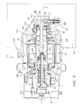
Figure 2 is a sectional view of the generator connected to the accessory gearbox; -
Figure 3 is a sectional view of the generator disconnected from the accessory gearbox; and -
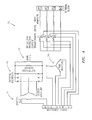
Figure 4 is an electrical schematic of the generator. -
Figure 1 schematically illustrates agenerator 20 which mounts to an aircraft accessory gearbox AG (illustrated schematically) though adrive gear 20G which rotates about a generator axis of rotation A to form anaccessory gearbox system 10. It should be understood that thegenerator 20 may alternatively be a starter generator. - The
generator 20 includes agenerator housing 20H which defines amounting flange 20F that is axially outboard of thedrive gear 20G relative to the accessory gearbox AG. Thedrive gear 20G extends through a side area of thegenerator housing 20H at ascallop 21 to mesh with the geartrain G within the accessory gearbox AG. Thedrive gear 20G is integral with the geartrain G of the accessory gearbox AG. That is, thedrive gear 20G is part of the geartrain G such that gears downstream of thedrive gear 20G are utilized to drive associated accessory systems. - With reference to
Figure 2 , thegenerator 20 generally includes a maingenerator power section 22, anexciter 24, arectifier assembly 26 and an optional permanent magnet generator (PMG) 28. Thegenerator 20 provides a packaging arrangement in which the heaviest portions of thegenerator 20 such as the maingenerator power section 22 are located generally adjacent to thegearbox mounting flange 20F and at least partially within the accessory gearbox AG. In the disclosed, non-limiting embodiment, a 4-Pole Integrally Mounted Gearbox Generator is illustrated. It should be appreciated that a 2-pole machine operates at a relatively higher speed and may have a relatively larger core than a 4-pole machine, however a 4-pole machine provides relatively greater rotor mechanical strength and may have relatively greater reliability. It should be appreciated that any pole count design generator may be integrated with an accessory gearbox AG as described herein. - The main
generator power section 22 provides alternating current (AC) power to an aircraft electrical bus (not shown). Theexciter 24 provides excitation current to the field of the maingenerator power section 22. Therectifier assembly 26 provides conversion of exciter armature alternating current (AC) power into direct current (DC) power for the main field portion of the maingenerator power section 22. If generator self-excitation is required, thegenerator 20 will also include thePMG 28 which provides AC power to the generator control unit for generator field excitation power. - The main
generator power section 22, theexciter 24 and theoptional PMG 28 are mounted on a commonrotor shaft assembly 30 which is supported within thegenerator housing 20H of thegenerator 20 bymain bearings gearbox mounting flange 20F and the maingenerator power section 22 are axially located between themain bearings exciter 24 is mounted on therotor shaft assembly 30 axially outboard of the second main bearing 34B. The PMG 28 is axially outboard of theexciter 24, andexciter 24 is mounted opposite the accessory gearbox AG, i.e. the main field/stator is located between theexciter 24 and thedrive gear 20G. - The
rotor shaft assembly 30 generally includes amain rotor shaft 36 and adisconnect shaft 38.Splines 36A are formed at an axially intermediate portion of an inner bore of themain rotor shaft 36 and mate withsplines 38A on thedisconnect shaft 38. Thedisconnect shaft 38 in the disclosed non-limiting embodiment includes a reduced diametertorsional section 38T and ashear section 38S. Thetorsional section 38T provides a relatively low torsional stiffness to minimize torque spike transmissibility. Theshear section 38S is essentially a fuse which will break should excessive gear train torque loads occur. - A
disconnect system 42 provides the ability to mechanically disengage thegenerator 20 from the accessory gearbox AG should a generator failure occur. Thedisconnect system 42 includesdisconnect jaws 38J adjacent to an end section of thedisconnect shaft 38 which selectively mesh withinput jaws 40J on aninput jaw plate 40. Aspring 41 biases thedisconnect shaft 38 away from themain rotor shaft 36. Theinput jaw plate 40 is keyed to thedrive gear 20G to transfer torque there between. Theinput jaw plate 40 permits selective relative rotation between themain rotor shaft 36 and thedrive gear 20G when thedisconnect jaw 38J is axially separated from theinput jaw 40J in response to actuation of thedisconnect system 42 as seen inFigure 3 when it is desired that there not be operation of thegenerator 20. - The
disconnect system 42 generally includes aplunger 44 which is selectively actuated by an electric/thermal solenoid 46. When actuated, theplunger 44 is moved into the position illustrated inFigure 3 , and rides along aramp helix 48 of thedisconnect shaft 38 to alockout diameter 50 which maintains thedisconnect jaw 38J axially separated from theinput jaw plate 40. That is, engagement of theplunger 44 with theramp helix 48 results in axial translation of thedisconnect shaft 38 along thesplined interface 36A-38A to separate thedisconnect jaw 38J from theinput jaw 40J which disconnects thedrive gear 20G from therotor shaft assembly 30. In one non-limiting embodiment, the lockout diameter is adistal end 38E of saiddisconnect shaft 38. - With reference to
Figure 3 , once thejaws rotor shaft assembly 30 ceases and the speed of thegenerator 20 coasts down to zero rpm through a drive gear bearing 52 packaged between therotor drive gear 20G and therotor shaft assembly 30. In one non-limiting embodiment, the drive gear bearing 52 is axially outboard of the main bearing 34A. The drive gear bearing 52 allows thedrive gear 20G to continue rotation and thereby transmit power to any downstream systems. If a generator failure should occur, for example, thegenerator 20 may be disconnected from the accessory gearbox AG without effect to downstream systems which are in meshed engagement through the geartrain G. That is, the accessory gearbox AG can still drive the downstream system with thegenerator 20 disconnected from the accessory gearbox AG even thoughdrive gear 20G is integral with geartrain G. - The
disconnect system 42 can be electrically actuated via the electric/thermal solenoid 46 or direct mechanical actuation through, for example, melting of lock such as a eutectic solder. Thedisconnect system 42 may be externally resettable in a manual manner during a maintenance procedure. - The
rectifier assembly 26 is mounted internal to therotor shaft assembly 30. Therectifier assembly 26 typically includes three or sixdiscreet diodes 60 arranged such that they provide rectification of the AC power developed by theexciter 24. The DC output of therectifier assembly 26 is fed into the main field of the maingenerator power section 22. - Location of the
diodes 60 internal to therotor shaft assembly 30 provides an efficient use of space within thegenerator 20. Thediscreet diodes 60 and associated electrical connections are arranged in a compact fashion such that thediodes 60 readily will fit within adiode housing 62 fit into therotor shaft assembly 30. Thediode housing 62 provides support to thediodes 60, electrical connections and insulation of the various electrical circuits. It should be understood that additional components may be provided within thediode housing 62 to provide support and electrical insulation. - With reference to
Figure 4 , the three phase output of theexciter 24 is connected to the rotating rectifier AC connections and the DC output of therectifier assembly 26 is connected to the maingenerator power section 22. The AC output of theexciter 24 is provided to therectifier assembly 26 via lead wires which extend inward from theexciter 24 to therectifier assembly 26. The lead wires are attached to the individual windings within theexciter 24 and connected individually to the three AC circuits within therectifier assembly 26. The DC output of therectifier assembly 26 is connected to the maingenerator power section 22 via wires or bus bars which extend axially and radially from therectifier assembly 26 to the maingenerator power section 22. - The
generator 20 arrangement disclosed herein also allows a resolver (not shown) to be packaged therein. The resolver is a rotary device that includes a rotor and a stator. The resolver rotor is mounted to therotor shaft assembly 30 and the stator is mounted to the housing. The resolver provides an electrical signal that can be used by a control unit for the generator or starter/generator to identify the position of the generator or starter/generator rotor relative to the housing. The exact construction of the resolver rotor and stator varies, and may consist of a wound rotor or a solid rotor. The resolver stator consists of one or more windings which couple with the rotating magnetic field produced by the resolver rotor. This coupling produces an electrical signal within the stator windings that is fed to the control unit to determine rotor position. Rotor position information is used by the control unit to determine the appropriate control signals that must be applied to the generator or starter/generator to achieve proper operation. - The
generator 20 provides a packaging arrangement in which the heaviest portions of thegenerator 20 are located close to thegearbox mounting flange 20F. This minimizes the overhung moment that must be reacted by the accessory gearbox AG and allows both the generator housing and accessory gearbox housings to be lighter. This packaging arrangement also minimizes housing and shaft/bearing weight between thegenerator 20 and accessory gearbox AG as they share components. - Even with the minimized overhung moment, the
generator 20 provides a packaging arrangement that maintains desired generator design features such as a generator mechanical input shaft shear fuse (shear section) should excessive gear train torque loads occur, a shaft with a relatively low torsional stiffness to minimize torque spike transmissibility, the ability to mechanically disengage (mechanically disconnect) the generator from the gearbox if a generator failure should occur, the ability to package a resolver for start performance, and a shaft internal rectifier assembly packaging arrangement. - It should be understood that relative positional terms such as "forward," "aft," "upper," "lower," "above," "below," and the like are with reference to the normal operational attitude of the vehicle and should not be considered otherwise limiting.
- It should be understood that like reference numerals identify corresponding or similar elements throughout the several drawings. It should also be understood that although a particular component arrangement is disclosed in the illustrated embodiment, other arrangements will benefit herefrom,
- Although particular step sequences are shown, described, and claimed, it should be understood that steps may be performed in any order, separated or combined unless otherwise indicated and will still benefit from the present disclosure.
- The foregoing description is exemplary rather than defined by the limitations within. Various non-limiting embodiments are disclosed herein, however, one of ordinary skill in the art would recognize that various modifications and variations in light of the above teachings may fall within the scope of the appended claims. It is therefore to be understood that within the scope of the appended claims, the disclosure may be practiced other than as specifically described. For that reason, the appended claims should be studied to determine true scope and content.
Claims (15)
- An accessory system comprising:an accessory gearbox which includes a geartrain; anda 4-Pole generator integrally mounted with said accessory gearbox such that a drive gear of said generator is in meshing engagement with said geartrain.
- The accessory system as recited in claim 1, wherein said geartrain includes a first and/or a second gear which are both in meshed engagement with said drive gear.
- The accessory system as recited in claim 1 or 2, wherein said geartrain is drivable with said drive gear disconnected from said generator.
- The accessory system as recited in claim 1, 2 or 3, further comprising:a generator housing which defines a scallop, said drive gear extending through an opening formed through said scallop.
- The accessory system as recited in claim 4, further comprising a mounting flange defined by said generator housing, said mounting flange being axially located adjacent to a main generator power section.
- A 4-Pole generator comprising:a generator housing which defines a flange;a drive shaft assembly supported within said generator housing; anda main generator power section supported on said drive shaft assembly axially adjacent said flange.
- The generator as recited in claim 6, further comprising:a drive gear selectively connected to said drive shaft assembly through a disconnect system.
- The generator as recited in claim 7, wherein said disconnect system further comprises:a main rotor shaft which defines main shaft splines;a disconnect shaft which defines disconnect shaft splines and disconnect jaws, said disconnect shaft splines mating with said main shaft splines;an input jaw plate keyed to said drive gear for rotation therewith, said input jaw plate defining input jaws which selectively mesh with said disconnect jaws, said disconnect shaft being axially movable in response to a disconnect system which axially separates said input jaws and said disconnect jaws to permit relative rotation between said main rotor shaft and said drive gear through a drive gear bearing.
- A generator comprising:a main rotor shaft which defines main shaft splines;a disconnect shaft which defines disconnect shaft splines and disconnect jaws, said disconnect shaft splines mating with said main shaft splines;a drive gear mounted to said main rotor shaft though a drive gear bearing;an input jaw plate keyed to said drive gear for rotation therewith, said input jaw plate defining input jaws which selectively mesh with said disconnect jaws, said disconnect shaft being axially movable in response to a disconnect system which axially separates said input jaws and said disconnect jaws to permit relative rotation between said main rotor shaft and said drive gear through said drive gear bearing.
- The generator as recited in claim 8 or 9, wherein said main shaft splines are formed on an inner bore of said main rotor shaft.
- The generator as recited in claim 8, 9 or 10, wherein said disconnect system includes a disconnect plunger which selectively contacts a ramp helix on said disconnect shaft to axially drive said disconnect shaft relative to said main rotor shaft along said main shaft splines and said disconnect shaft splines.
- The generator as recited in claim 8, 9, 10 or 11, wherein said drive gear extends through an opening defined through a scallop formed in a gearbox housing;
preferably wherein said drive gear is axially outboard of a first main bearing which supports said main rotor shaft within said gearbox housing. - The generator as recited in claim 8, 9, 10, 11 or 12, further comprising a main generator power section supported on said main rotor shaft inboard of said first main bearing and a second main bearing; preferably further comprising a mounting flange defined by said generator housing, said mounting flange axially located between said first main bearing and said second main bearing.
- The generator as recited in any of claims 8 to 13, wherein said main rotor shaft includes a shear section; and/or wherein said main rotor shaft includes a torsionally compliant section.
- The accessory system as recited in any of claims 1 to 5 wherein the generator comprises one or more features of claims 6 to 14.
Applications Claiming Priority (3)
| Application Number | Priority Date | Filing Date | Title |
|---|---|---|---|
| US28445109P | 2009-12-18 | 2009-12-18 | |
| US28445209P | 2009-12-18 | 2009-12-18 | |
| US28445309P | 2009-12-18 | 2009-12-18 |
Publications (3)
| Publication Number | Publication Date |
|---|---|
| EP2337189A2 true EP2337189A2 (en) | 2011-06-22 |
| EP2337189A3 EP2337189A3 (en) | 2014-08-13 |
| EP2337189B1 EP2337189B1 (en) | 2016-08-10 |
Family
ID=43531029
Family Applications (3)
| Application Number | Title | Priority Date | Filing Date |
|---|---|---|---|
| EP10252148A Withdrawn EP2337190A2 (en) | 2009-12-18 | 2010-12-17 | Generator packaging arrangement |
| EP10196060.7A Active EP2337189B1 (en) | 2009-12-18 | 2010-12-20 | Generator packaging arrangement |
| EP10196059.9A Active EP2337188B1 (en) | 2009-12-18 | 2010-12-20 | Generator packaging arrangement |
Family Applications Before (1)
| Application Number | Title | Priority Date | Filing Date |
|---|---|---|---|
| EP10252148A Withdrawn EP2337190A2 (en) | 2009-12-18 | 2010-12-17 | Generator packaging arrangement |
Family Applications After (1)
| Application Number | Title | Priority Date | Filing Date |
|---|---|---|---|
| EP10196059.9A Active EP2337188B1 (en) | 2009-12-18 | 2010-12-20 | Generator packaging arrangement |
Country Status (3)
| Country | Link |
|---|---|
| US (3) | US20110148235A1 (en) |
| EP (3) | EP2337190A2 (en) |
| CN (3) | CN102148549A (en) |
Families Citing this family (9)
| Publication number | Priority date | Publication date | Assignee | Title |
|---|---|---|---|---|
| US9650964B2 (en) * | 2010-12-28 | 2017-05-16 | General Electric Company | Accessory gearbox with a starter/generator |
| US10601281B2 (en) * | 2012-03-26 | 2020-03-24 | Joy Global Surface Mining Inc. | Modular direct drive system for an industrial machine |
| CN102857009B (en) * | 2012-04-21 | 2015-07-29 | 广东明阳风电产业集团有限公司 | A kind of wind turbine generator generator casing |
| JP5274702B1 (en) * | 2012-06-28 | 2013-08-28 | 株式会社一宮電機 | Motor drive system |
| FR2994939B1 (en) * | 2012-09-05 | 2014-08-22 | Turbomeca | ACCESSORIES HOUSING FOR CONTROLLING SHUTTERS OF AN AIRCRAFT |
| US9057407B2 (en) * | 2012-11-27 | 2015-06-16 | Hamilton Sundstrand Corporation | Disconnect assembly |
| US9611787B2 (en) | 2015-05-18 | 2017-04-04 | General Electric Company | Accessory apparatus and method of assembling accessories with a turbine engine |
| EP3494320B1 (en) * | 2016-08-05 | 2021-01-27 | Safran Electrical & Power | Shaft seize ring |
| US11134585B2 (en) * | 2019-05-31 | 2021-09-28 | Hamilton Sundstrand Corporation | Aircraft power electronic unit and method of cooling |
Family Cites Families (37)
| Publication number | Priority date | Publication date | Assignee | Title |
|---|---|---|---|---|
| US2454120A (en) * | 1947-04-30 | 1948-11-16 | Westinghouse Electric Corp | Dual generator ventilation |
| GB1259776A (en) * | 1968-04-19 | 1972-01-12 | Plessey Co Ltd | Improvements in or relating to electrical machines |
| US3800212A (en) * | 1973-02-26 | 1974-03-26 | Burroughs Corp | Mechanical-to-electrical conversion system |
| US4447737A (en) * | 1980-12-29 | 1984-05-08 | Lockheed Corporation | Variable frequency induction generator |
| US4545470A (en) | 1983-12-14 | 1985-10-08 | Sundstrand Corporation | Narrow tolerance range slip clutch |
| US4694187A (en) * | 1986-01-13 | 1987-09-15 | Westinghouse Electric Corp. | Electromechanical constant speed drive generating system |
| JPH01148068U (en) * | 1988-04-01 | 1989-10-13 | ||
| US4997072A (en) * | 1989-08-21 | 1991-03-05 | Sundstrand Corporation | Rotating concentric shaft disconnect actuating mechanism for an integrated drive generator |
| US5300848A (en) * | 1989-11-14 | 1994-04-05 | Sunstrand Corporation | Dual permanent magnet generator planetary gear actuator and rotor phase shifting method |
| US5023789A (en) * | 1990-06-04 | 1991-06-11 | Sundstrand Corporation | Temperature compensated closed loop control of a hydraulically controlled clutch and APU starting system |
| US5029689A (en) | 1990-09-10 | 1991-07-09 | Sundstrand Corporation | Spring clutch assembly for use in a transmission |
| US5174109A (en) | 1990-10-25 | 1992-12-29 | Sundstrand Corporation | Clutch to disconnect loads during turbine start-up |
| US5319272A (en) * | 1992-07-14 | 1994-06-07 | Eemco/Datron, Inc. | Miniature rotating rectifier assembly |
| US5325009A (en) * | 1993-05-07 | 1994-06-28 | Sundstrand Corporation | Rotor shaft with integral wedge retainers for core of a two-pole generator |
| JP2967103B2 (en) * | 1993-05-24 | 1999-10-25 | 株式会社エクォス・リサーチ | Hybrid vehicle |
| US5625511A (en) * | 1995-01-11 | 1997-04-29 | International Business Machines Corporation | Stepped spindle motor shaft to reduce disk drive acoustic noise |
| US5562190A (en) | 1995-06-07 | 1996-10-08 | Sundstrand Corporation | Hydraulic clutch control system with fluid coupling pre-heat circuit for rapid response at low ambient temperatures |
| US6260667B1 (en) * | 1999-04-15 | 2001-07-17 | Hamilton Sundstrand Corporation | Rotor containment brake |
| DE10102255A1 (en) * | 2001-01-19 | 2002-08-01 | Aloys Wobben | Wind turbine with a hollow shaft for rotor hub and generator |
| SE519200C2 (en) * | 2001-06-05 | 2003-01-28 | Volvo Aero Corp | Gas turbine device with an arrangement for operating one or more auxiliary appliances |
| US6897581B2 (en) * | 2002-10-04 | 2005-05-24 | Honeywell International Inc. | High speed generator with the main rotor housed inside the shaft |
| US6713916B1 (en) * | 2002-10-31 | 2004-03-30 | Black & Decker Inc. | Electric motor assembly |
| US7131275B2 (en) | 2002-12-06 | 2006-11-07 | Hamilton Sundstrand | Gas turbine engine system having an electric starter motor with integral clutch |
| AU2004302757A1 (en) * | 2003-01-31 | 2005-03-10 | Light Engineering, Inc. | Efficient high-speed electric device using low-loss materials |
| US8347647B2 (en) * | 2004-09-22 | 2013-01-08 | Hamilton Sundstrand Corporation | Air cycle machine for an aircraft environmental control system |
| US20060087123A1 (en) * | 2004-10-22 | 2006-04-27 | Stout David E | Dual-rotor, single input/output starter-generator |
| US7805947B2 (en) * | 2005-05-19 | 2010-10-05 | Djamal Moulebhar | Aircraft with disengageable engine and auxiliary power unit components |
| DE102005049879A1 (en) * | 2005-10-17 | 2007-04-19 | Rolls-Royce Deutschland Ltd & Co Kg | Generator for an engine |
| US7627941B2 (en) * | 2005-10-26 | 2009-12-08 | Hamilton Sundstrand Corporation | Fixture for aligning motor assembly |
| FR2897895A1 (en) * | 2006-02-27 | 2007-08-31 | Hispano Suiza Sa | Transmission unit and starter-generator assembly for gas turbine, has synchronous generator and exciter placed on sides of pinion and with respective rotors mounted on shaft, and transmission unit and starter-generator placed in common case |
| JP4691168B2 (en) * | 2006-02-27 | 2011-06-01 | イスパノ・シユイザ | Incorporation of starter / generator module in gas turbine transmission housing |
| US7687960B2 (en) * | 2006-12-28 | 2010-03-30 | Hydrogen Engine Center | Pigtailed stator windings for electrical generator |
| TWM318070U (en) * | 2007-01-26 | 2007-09-01 | Ren-Hau Dai | An electricity-generating manual apparatus |
| US20090042656A1 (en) * | 2007-08-07 | 2009-02-12 | Ricoh Company, Limited | Image Forming apparatus |
| EP2079152A3 (en) * | 2008-01-11 | 2011-04-13 | Goodrich Corporation | Mounting arrangement for an electrical generator |
| US7728477B2 (en) * | 2008-01-17 | 2010-06-01 | Honeywell International Inc. | Dual purpose permanent magnet exciter |
| US8172512B2 (en) * | 2008-04-23 | 2012-05-08 | Hamilton Sundstrand Corporation | Accessory gearbox system with compressor driven seal air supply |
-
2010
- 2010-05-25 US US12/787,381 patent/US20110148235A1/en not_active Abandoned
- 2010-05-25 US US12/787,353 patent/US8796892B2/en active Active
- 2010-05-25 US US12/787,365 patent/US8432079B2/en active Active
- 2010-12-17 CN CN2010105939450A patent/CN102148549A/en active Pending
- 2010-12-17 EP EP10252148A patent/EP2337190A2/en not_active Withdrawn
- 2010-12-17 CN CN2010105939889A patent/CN102104293A/en active Pending
- 2010-12-17 CN CN201010594003.4A patent/CN102104294B/en active Active
- 2010-12-20 EP EP10196060.7A patent/EP2337189B1/en active Active
- 2010-12-20 EP EP10196059.9A patent/EP2337188B1/en active Active
Non-Patent Citations (1)
| Title |
|---|
| None |
Also Published As
| Publication number | Publication date |
|---|---|
| CN102148549A (en) | 2011-08-10 |
| US20110148235A1 (en) | 2011-06-23 |
| EP2337189B1 (en) | 2016-08-10 |
| EP2337189A3 (en) | 2014-08-13 |
| US20110148233A1 (en) | 2011-06-23 |
| CN102104294A (en) | 2011-06-22 |
| CN102104294B (en) | 2014-01-29 |
| US8432079B2 (en) | 2013-04-30 |
| EP2337190A2 (en) | 2011-06-22 |
| EP2337188A2 (en) | 2011-06-22 |
| US20110148234A1 (en) | 2011-06-23 |
| US8796892B2 (en) | 2014-08-05 |
| EP2337188A3 (en) | 2014-08-13 |
| CN102104293A (en) | 2011-06-22 |
| EP2337188B1 (en) | 2016-08-10 |
Similar Documents
| Publication | Publication Date | Title |
|---|---|---|
| EP2337189B1 (en) | Generator packaging arrangement | |
| US20160329777A1 (en) | Reversible electrical machine for an aircraft | |
| US20060087123A1 (en) | Dual-rotor, single input/output starter-generator | |
| US4476395A (en) | Tandem-generator design for aircraft | |
| EP3276800B1 (en) | Integrated brushless starter generator | |
| US6467725B1 (en) | Electrical generator an aero-engine including such a generator, and an aircraft including such a generator | |
| US12030662B2 (en) | Propulsion system for a helicopter | |
| JP5469167B2 (en) | Transmission having a transmission housing | |
| JP6248203B2 (en) | Method for starting an aircraft engine | |
| CA2684483A1 (en) | Dual structured aircraft engine starter/generator | |
| JP2012515297A (en) | Electromagnetic continuously variable power split turbine combined engine, and engine and vehicle including turbine combined engine | |
| US6333577B1 (en) | Automotive AC dynamo-electric machine | |
| JP2000295827A (en) | Vehicle power supply system | |
| EP2081282A2 (en) | Dual purpose permanent magnet exciter | |
| EP0234055B1 (en) | Method and apparatus for starting an aircraft engine | |
| US6259166B1 (en) | Generator with double driving machinery | |
| GB2470479A (en) | A constant frequency starter drive | |
| JP2000108694A (en) | Driving device for power car | |
| US20100277030A1 (en) | Laminated stator assembly | |
| US11152837B2 (en) | Generator arrangements and methods of generating electric power with generator arrangements | |
| US20110132674A1 (en) | Internal combustion engine/hybrid transmission assembly | |
| JP2010126025A (en) | Power transmission | |
| US20250309728A1 (en) | Method and system for rapid starting of a combustion engine in a multi-engine aircraft | |
| EP0680129A1 (en) | Controlling start-up of electrically-powered equipment such as a compressor | |
| EP2104224A2 (en) | Fault clearing method for permanent magnet machines |
Legal Events
| Date | Code | Title | Description |
|---|---|---|---|
| PUAI | Public reference made under article 153(3) epc to a published international application that has entered the european phase |
Free format text: ORIGINAL CODE: 0009012 |
|
| AK | Designated contracting states |
Kind code of ref document: A2 Designated state(s): AL AT BE BG CH CY CZ DE DK EE ES FI FR GB GR HR HU IE IS IT LI LT LU LV MC MK MT NL NO PL PT RO RS SE SI SK SM TR |
|
| AX | Request for extension of the european patent |
Extension state: BA ME |
|
| PUAL | Search report despatched |
Free format text: ORIGINAL CODE: 0009013 |
|
| AK | Designated contracting states |
Kind code of ref document: A3 Designated state(s): AL AT BE BG CH CY CZ DE DK EE ES FI FR GB GR HR HU IE IS IT LI LT LU LV MC MK MT NL NO PL PT RO RS SE SI SK SM TR |
|
| AX | Request for extension of the european patent |
Extension state: BA ME |
|
| RIC1 | Information provided on ipc code assigned before grant |
Ipc: H02K 7/18 20060101ALI20140707BHEP Ipc: H02K 7/108 20060101ALI20140707BHEP Ipc: H02K 7/102 20060101ALN20140707BHEP Ipc: H02K 7/116 20060101AFI20140707BHEP |
|
| 17P | Request for examination filed |
Effective date: 20150206 |
|
| RBV | Designated contracting states (corrected) |
Designated state(s): AL AT BE BG CH CY CZ DE DK EE ES FI FR GB GR HR HU IE IS IT LI LT LU LV MC MK MT NL NO PL PT RO RS SE SI SK SM TR |
|
| RIC1 | Information provided on ipc code assigned before grant |
Ipc: H02K 7/116 20060101AFI20160113BHEP Ipc: H02K 7/18 20060101ALI20160113BHEP Ipc: H02K 7/102 20060101ALN20160113BHEP Ipc: H02K 7/108 20060101ALI20160113BHEP Ipc: H02K 7/20 20060101ALN20160113BHEP |
|
| GRAP | Despatch of communication of intention to grant a patent |
Free format text: ORIGINAL CODE: EPIDOSNIGR1 |
|
| INTG | Intention to grant announced |
Effective date: 20160223 |
|
| GRAS | Grant fee paid |
Free format text: ORIGINAL CODE: EPIDOSNIGR3 |
|
| GRAA | (expected) grant |
Free format text: ORIGINAL CODE: 0009210 |
|
| AK | Designated contracting states |
Kind code of ref document: B1 Designated state(s): AL AT BE BG CH CY CZ DE DK EE ES FI FR GB GR HR HU IE IS IT LI LT LU LV MC MK MT NL NO PL PT RO RS SE SI SK SM TR |
|
| REG | Reference to a national code |
Ref country code: GB Ref legal event code: FG4D |
|
| REG | Reference to a national code |
Ref country code: CH Ref legal event code: EP Ref country code: AT Ref legal event code: REF Ref document number: 819822 Country of ref document: AT Kind code of ref document: T Effective date: 20160815 |
|
| REG | Reference to a national code |
Ref country code: IE Ref legal event code: FG4D |
|
| REG | Reference to a national code |
Ref country code: DE Ref legal event code: R096 Ref document number: 602010035310 Country of ref document: DE |
|
| REG | Reference to a national code |
Ref country code: FR Ref legal event code: PLFP Year of fee payment: 7 |
|
| REG | Reference to a national code |
Ref country code: LT Ref legal event code: MG4D |
|
| REG | Reference to a national code |
Ref country code: NL Ref legal event code: MP Effective date: 20160810 |
|
| REG | Reference to a national code |
Ref country code: AT Ref legal event code: MK05 Ref document number: 819822 Country of ref document: AT Kind code of ref document: T Effective date: 20160810 |
|
| PG25 | Lapsed in a contracting state [announced via postgrant information from national office to epo] |
Ref country code: FI Free format text: LAPSE BECAUSE OF FAILURE TO SUBMIT A TRANSLATION OF THE DESCRIPTION OR TO PAY THE FEE WITHIN THE PRESCRIBED TIME-LIMIT Effective date: 20160810 Ref country code: IS Free format text: LAPSE BECAUSE OF FAILURE TO SUBMIT A TRANSLATION OF THE DESCRIPTION OR TO PAY THE FEE WITHIN THE PRESCRIBED TIME-LIMIT Effective date: 20161210 Ref country code: RS Free format text: LAPSE BECAUSE OF FAILURE TO SUBMIT A TRANSLATION OF THE DESCRIPTION OR TO PAY THE FEE WITHIN THE PRESCRIBED TIME-LIMIT Effective date: 20160810 Ref country code: HR Free format text: LAPSE BECAUSE OF FAILURE TO SUBMIT A TRANSLATION OF THE DESCRIPTION OR TO PAY THE FEE WITHIN THE PRESCRIBED TIME-LIMIT Effective date: 20160810 Ref country code: NO Free format text: LAPSE BECAUSE OF FAILURE TO SUBMIT A TRANSLATION OF THE DESCRIPTION OR TO PAY THE FEE WITHIN THE PRESCRIBED TIME-LIMIT Effective date: 20161110 Ref country code: NL Free format text: LAPSE BECAUSE OF FAILURE TO SUBMIT A TRANSLATION OF THE DESCRIPTION OR TO PAY THE FEE WITHIN THE PRESCRIBED TIME-LIMIT Effective date: 20160810 Ref country code: IT Free format text: LAPSE BECAUSE OF FAILURE TO SUBMIT A TRANSLATION OF THE DESCRIPTION OR TO PAY THE FEE WITHIN THE PRESCRIBED TIME-LIMIT Effective date: 20160810 Ref country code: LT Free format text: LAPSE BECAUSE OF FAILURE TO SUBMIT A TRANSLATION OF THE DESCRIPTION OR TO PAY THE FEE WITHIN THE PRESCRIBED TIME-LIMIT Effective date: 20160810 |
|
| PG25 | Lapsed in a contracting state [announced via postgrant information from national office to epo] |
Ref country code: GR Free format text: LAPSE BECAUSE OF FAILURE TO SUBMIT A TRANSLATION OF THE DESCRIPTION OR TO PAY THE FEE WITHIN THE PRESCRIBED TIME-LIMIT Effective date: 20161111 Ref country code: AT Free format text: LAPSE BECAUSE OF FAILURE TO SUBMIT A TRANSLATION OF THE DESCRIPTION OR TO PAY THE FEE WITHIN THE PRESCRIBED TIME-LIMIT Effective date: 20160810 Ref country code: LV Free format text: LAPSE BECAUSE OF FAILURE TO SUBMIT A TRANSLATION OF THE DESCRIPTION OR TO PAY THE FEE WITHIN THE PRESCRIBED TIME-LIMIT Effective date: 20160810 Ref country code: ES Free format text: LAPSE BECAUSE OF FAILURE TO SUBMIT A TRANSLATION OF THE DESCRIPTION OR TO PAY THE FEE WITHIN THE PRESCRIBED TIME-LIMIT Effective date: 20160810 Ref country code: PL Free format text: LAPSE BECAUSE OF FAILURE TO SUBMIT A TRANSLATION OF THE DESCRIPTION OR TO PAY THE FEE WITHIN THE PRESCRIBED TIME-LIMIT Effective date: 20160810 Ref country code: SE Free format text: LAPSE BECAUSE OF FAILURE TO SUBMIT A TRANSLATION OF THE DESCRIPTION OR TO PAY THE FEE WITHIN THE PRESCRIBED TIME-LIMIT Effective date: 20160810 Ref country code: PT Free format text: LAPSE BECAUSE OF FAILURE TO SUBMIT A TRANSLATION OF THE DESCRIPTION OR TO PAY THE FEE WITHIN THE PRESCRIBED TIME-LIMIT Effective date: 20161212 |
|
| PG25 | Lapsed in a contracting state [announced via postgrant information from national office to epo] |
Ref country code: RO Free format text: LAPSE BECAUSE OF FAILURE TO SUBMIT A TRANSLATION OF THE DESCRIPTION OR TO PAY THE FEE WITHIN THE PRESCRIBED TIME-LIMIT Effective date: 20160810 Ref country code: EE Free format text: LAPSE BECAUSE OF FAILURE TO SUBMIT A TRANSLATION OF THE DESCRIPTION OR TO PAY THE FEE WITHIN THE PRESCRIBED TIME-LIMIT Effective date: 20160810 |
|
| REG | Reference to a national code |
Ref country code: DE Ref legal event code: R097 Ref document number: 602010035310 Country of ref document: DE |
|
| PG25 | Lapsed in a contracting state [announced via postgrant information from national office to epo] |
Ref country code: DK Free format text: LAPSE BECAUSE OF FAILURE TO SUBMIT A TRANSLATION OF THE DESCRIPTION OR TO PAY THE FEE WITHIN THE PRESCRIBED TIME-LIMIT Effective date: 20160810 Ref country code: CZ Free format text: LAPSE BECAUSE OF FAILURE TO SUBMIT A TRANSLATION OF THE DESCRIPTION OR TO PAY THE FEE WITHIN THE PRESCRIBED TIME-LIMIT Effective date: 20160810 Ref country code: BG Free format text: LAPSE BECAUSE OF FAILURE TO SUBMIT A TRANSLATION OF THE DESCRIPTION OR TO PAY THE FEE WITHIN THE PRESCRIBED TIME-LIMIT Effective date: 20161110 Ref country code: SM Free format text: LAPSE BECAUSE OF FAILURE TO SUBMIT A TRANSLATION OF THE DESCRIPTION OR TO PAY THE FEE WITHIN THE PRESCRIBED TIME-LIMIT Effective date: 20160810 Ref country code: BE Free format text: LAPSE BECAUSE OF FAILURE TO SUBMIT A TRANSLATION OF THE DESCRIPTION OR TO PAY THE FEE WITHIN THE PRESCRIBED TIME-LIMIT Effective date: 20160810 Ref country code: SK Free format text: LAPSE BECAUSE OF FAILURE TO SUBMIT A TRANSLATION OF THE DESCRIPTION OR TO PAY THE FEE WITHIN THE PRESCRIBED TIME-LIMIT Effective date: 20160810 |
|
| PLBE | No opposition filed within time limit |
Free format text: ORIGINAL CODE: 0009261 |
|
| STAA | Information on the status of an ep patent application or granted ep patent |
Free format text: STATUS: NO OPPOSITION FILED WITHIN TIME LIMIT |
|
| REG | Reference to a national code |
Ref country code: DE Ref legal event code: R119 Ref document number: 602010035310 Country of ref document: DE |
|
| 26N | No opposition filed |
Effective date: 20170511 |
|
| REG | Reference to a national code |
Ref country code: CH Ref legal event code: PL |
|
| PG25 | Lapsed in a contracting state [announced via postgrant information from national office to epo] |
Ref country code: SI Free format text: LAPSE BECAUSE OF FAILURE TO SUBMIT A TRANSLATION OF THE DESCRIPTION OR TO PAY THE FEE WITHIN THE PRESCRIBED TIME-LIMIT Effective date: 20160810 |
|
| PG25 | Lapsed in a contracting state [announced via postgrant information from national office to epo] |
Ref country code: MC Free format text: LAPSE BECAUSE OF FAILURE TO SUBMIT A TRANSLATION OF THE DESCRIPTION OR TO PAY THE FEE WITHIN THE PRESCRIBED TIME-LIMIT Effective date: 20160810 |
|
| REG | Reference to a national code |
Ref country code: IE Ref legal event code: MM4A |
|
| PG25 | Lapsed in a contracting state [announced via postgrant information from national office to epo] |
Ref country code: LI Free format text: LAPSE BECAUSE OF NON-PAYMENT OF DUE FEES Effective date: 20161231 Ref country code: CH Free format text: LAPSE BECAUSE OF NON-PAYMENT OF DUE FEES Effective date: 20161231 Ref country code: LU Free format text: LAPSE BECAUSE OF NON-PAYMENT OF DUE FEES Effective date: 20161220 |
|
| REG | Reference to a national code |
Ref country code: FR Ref legal event code: PLFP Year of fee payment: 8 |
|
| PG25 | Lapsed in a contracting state [announced via postgrant information from national office to epo] |
Ref country code: DE Free format text: LAPSE BECAUSE OF NON-PAYMENT OF DUE FEES Effective date: 20170701 Ref country code: IE Free format text: LAPSE BECAUSE OF NON-PAYMENT OF DUE FEES Effective date: 20161220 |
|
| PG25 | Lapsed in a contracting state [announced via postgrant information from national office to epo] |
Ref country code: CY Free format text: LAPSE BECAUSE OF FAILURE TO SUBMIT A TRANSLATION OF THE DESCRIPTION OR TO PAY THE FEE WITHIN THE PRESCRIBED TIME-LIMIT Effective date: 20160810 Ref country code: HU Free format text: LAPSE BECAUSE OF FAILURE TO SUBMIT A TRANSLATION OF THE DESCRIPTION OR TO PAY THE FEE WITHIN THE PRESCRIBED TIME-LIMIT; INVALID AB INITIO Effective date: 20101220 |
|
| PG25 | Lapsed in a contracting state [announced via postgrant information from national office to epo] |
Ref country code: TR Free format text: LAPSE BECAUSE OF FAILURE TO SUBMIT A TRANSLATION OF THE DESCRIPTION OR TO PAY THE FEE WITHIN THE PRESCRIBED TIME-LIMIT Effective date: 20160810 Ref country code: MK Free format text: LAPSE BECAUSE OF FAILURE TO SUBMIT A TRANSLATION OF THE DESCRIPTION OR TO PAY THE FEE WITHIN THE PRESCRIBED TIME-LIMIT Effective date: 20160810 |
|
| PG25 | Lapsed in a contracting state [announced via postgrant information from national office to epo] |
Ref country code: MT Free format text: LAPSE BECAUSE OF NON-PAYMENT OF DUE FEES Effective date: 20161220 |
|
| PG25 | Lapsed in a contracting state [announced via postgrant information from national office to epo] |
Ref country code: AL Free format text: LAPSE BECAUSE OF FAILURE TO SUBMIT A TRANSLATION OF THE DESCRIPTION OR TO PAY THE FEE WITHIN THE PRESCRIBED TIME-LIMIT Effective date: 20160810 |
|
| P01 | Opt-out of the competence of the unified patent court (upc) registered |
Effective date: 20230522 |
|
| PGFP | Annual fee paid to national office [announced via postgrant information from national office to epo] |
Ref country code: GB Payment date: 20251119 Year of fee payment: 16 |
|
| PGFP | Annual fee paid to national office [announced via postgrant information from national office to epo] |
Ref country code: FR Payment date: 20251119 Year of fee payment: 16 |