EP2337119A2 - Medium or large battery pack including electrode connection device - Google Patents
Medium or large battery pack including electrode connection device Download PDFInfo
- Publication number
- EP2337119A2 EP2337119A2 EP09820702A EP09820702A EP2337119A2 EP 2337119 A2 EP2337119 A2 EP 2337119A2 EP 09820702 A EP09820702 A EP 09820702A EP 09820702 A EP09820702 A EP 09820702A EP 2337119 A2 EP2337119 A2 EP 2337119A2
- Authority
- EP
- European Patent Office
- Prior art keywords
- battery pack
- connecting member
- conductive connecting
- shut
- insulative
- Prior art date
- Legal status (The legal status is an assumption and is not a legal conclusion. Google has not performed a legal analysis and makes no representation as to the accuracy of the status listed.)
- Granted
Links
Images


Classifications
-
- H—ELECTRICITY
- H01—ELECTRIC ELEMENTS
- H01M—PROCESSES OR MEANS, e.g. BATTERIES, FOR THE DIRECT CONVERSION OF CHEMICAL ENERGY INTO ELECTRICAL ENERGY
- H01M50/00—Constructional details or processes of manufacture of the non-active parts of electrochemical cells other than fuel cells, e.g. hybrid cells
- H01M50/50—Current conducting connections for cells or batteries
- H01M50/543—Terminals
-
- H—ELECTRICITY
- H01—ELECTRIC ELEMENTS
- H01M—PROCESSES OR MEANS, e.g. BATTERIES, FOR THE DIRECT CONVERSION OF CHEMICAL ENERGY INTO ELECTRICAL ENERGY
- H01M50/00—Constructional details or processes of manufacture of the non-active parts of electrochemical cells other than fuel cells, e.g. hybrid cells
- H01M50/50—Current conducting connections for cells or batteries
- H01M50/572—Means for preventing undesired use or discharge
- H01M50/574—Devices or arrangements for the interruption of current
- H01M50/579—Devices or arrangements for the interruption of current in response to shock
-
- H—ELECTRICITY
- H01—ELECTRIC ELEMENTS
- H01M—PROCESSES OR MEANS, e.g. BATTERIES, FOR THE DIRECT CONVERSION OF CHEMICAL ENERGY INTO ELECTRICAL ENERGY
- H01M50/00—Constructional details or processes of manufacture of the non-active parts of electrochemical cells other than fuel cells, e.g. hybrid cells
- H01M50/20—Mountings; Secondary casings or frames; Racks, modules or packs; Suspension devices; Shock absorbers; Transport or carrying devices; Holders
- H01M50/204—Racks, modules or packs for multiple batteries or multiple cells
-
- H—ELECTRICITY
- H01—ELECTRIC ELEMENTS
- H01M—PROCESSES OR MEANS, e.g. BATTERIES, FOR THE DIRECT CONVERSION OF CHEMICAL ENERGY INTO ELECTRICAL ENERGY
- H01M50/00—Constructional details or processes of manufacture of the non-active parts of electrochemical cells other than fuel cells, e.g. hybrid cells
- H01M50/20—Mountings; Secondary casings or frames; Racks, modules or packs; Suspension devices; Shock absorbers; Transport or carrying devices; Holders
- H01M50/296—Mountings; Secondary casings or frames; Racks, modules or packs; Suspension devices; Shock absorbers; Transport or carrying devices; Holders characterised by terminals of battery packs
-
- H—ELECTRICITY
- H01—ELECTRIC ELEMENTS
- H01M—PROCESSES OR MEANS, e.g. BATTERIES, FOR THE DIRECT CONVERSION OF CHEMICAL ENERGY INTO ELECTRICAL ENERGY
- H01M50/00—Constructional details or processes of manufacture of the non-active parts of electrochemical cells other than fuel cells, e.g. hybrid cells
- H01M50/50—Current conducting connections for cells or batteries
- H01M50/502—Interconnectors for connecting terminals of adjacent batteries; Interconnectors for connecting cells outside a battery casing
- H01M50/503—Interconnectors for connecting terminals of adjacent batteries; Interconnectors for connecting cells outside a battery casing characterised by the shape of the interconnectors
-
- H—ELECTRICITY
- H01—ELECTRIC ELEMENTS
- H01M—PROCESSES OR MEANS, e.g. BATTERIES, FOR THE DIRECT CONVERSION OF CHEMICAL ENERGY INTO ELECTRICAL ENERGY
- H01M50/00—Constructional details or processes of manufacture of the non-active parts of electrochemical cells other than fuel cells, e.g. hybrid cells
- H01M50/50—Current conducting connections for cells or batteries
- H01M50/502—Interconnectors for connecting terminals of adjacent batteries; Interconnectors for connecting cells outside a battery casing
- H01M50/505—Interconnectors for connecting terminals of adjacent batteries; Interconnectors for connecting cells outside a battery casing comprising a single busbar
-
- H—ELECTRICITY
- H01—ELECTRIC ELEMENTS
- H01M—PROCESSES OR MEANS, e.g. BATTERIES, FOR THE DIRECT CONVERSION OF CHEMICAL ENERGY INTO ELECTRICAL ENERGY
- H01M50/00—Constructional details or processes of manufacture of the non-active parts of electrochemical cells other than fuel cells, e.g. hybrid cells
- H01M50/50—Current conducting connections for cells or batteries
- H01M50/571—Methods or arrangements for affording protection against corrosion; Selection of materials therefor
-
- H—ELECTRICITY
- H01—ELECTRIC ELEMENTS
- H01M—PROCESSES OR MEANS, e.g. BATTERIES, FOR THE DIRECT CONVERSION OF CHEMICAL ENERGY INTO ELECTRICAL ENERGY
- H01M2200/00—Safety devices for primary or secondary batteries
-
- Y—GENERAL TAGGING OF NEW TECHNOLOGICAL DEVELOPMENTS; GENERAL TAGGING OF CROSS-SECTIONAL TECHNOLOGIES SPANNING OVER SEVERAL SECTIONS OF THE IPC; TECHNICAL SUBJECTS COVERED BY FORMER USPC CROSS-REFERENCE ART COLLECTIONS [XRACs] AND DIGESTS
- Y02—TECHNOLOGIES OR APPLICATIONS FOR MITIGATION OR ADAPTATION AGAINST CLIMATE CHANGE
- Y02E—REDUCTION OF GREENHOUSE GAS [GHG] EMISSIONS, RELATED TO ENERGY GENERATION, TRANSMISSION OR DISTRIBUTION
- Y02E60/00—Enabling technologies; Technologies with a potential or indirect contribution to GHG emissions mitigation
- Y02E60/10—Energy storage using batteries
Definitions
- the present invention relates to a middle or large-sized battery pack including an electrode terminal connecting device, and, more particularly, to a middle or large-sized battery pack having a plurality of electrically connected battery modules, the middle or large-sized battery pack including an electrode terminal connecting device, wherein the electrode terminal connecting device includes a conductive connecting member coupled to electrode terminals of the battery modules to electrically connect the electrode terminals of the battery modules to each other and a shut-off cutter mounted to the conductive connecting member to shut off the circuit of the conductive connecting member when impact is applied to the battery pack in the longitudinal direction of the battery pack.
- a secondary battery which can be charged and discharged, has been widely used as an energy source for wireless mobile devices. Also, the secondary battery has attracted considerable attention as a power source for electric vehicles (EV), hybrid electric vehicles (HEV), and plug-in hybrid electric vehicles (Plug-in HEV), which have been developed to solve problems, such as air pollution, caused by existing gasoline and diesel vehicles using fossil fuels.
- EV electric vehicles
- HEV hybrid electric vehicles
- Plug-in HEV plug-in hybrid electric vehicles
- Small-sized mobile devices use one or several battery cells for each device.
- middle or large-sized devices such as vehicles, use a middle or large-sized battery module having a plurality of battery cells electrically connected to one another because high power and large capacity are necessary for the middle or large-sized devices.
- a plurality of unit cells are mounted in a cartridge which connects the unit cells in series and/or in parallel to each other, and a plurality of cartridges are electrically connected to each other, thereby manufacturing a battery module.
- two or more battery modules are electrically connected to each other, thereby manufacturing a middle or large-sized battery pack or system providing higher power.
- such a middle or large-sized battery pack exhibits high safety with respect to deformation of the battery pack in the thickness thereof but low safety with respect to deformation of the battery pack in the electrode terminal direction of the battery cells.
- a short circuit occurs at electrode terminal regions of a battery module when external force caused due to, for example, vehicle collision is applied to the battery pack with the result the battery pack may catch fire or explode.
- the present invention has been made to solve the above problems, and other technical problems that have yet to be resolved.
- a middle or large-sized battery pack including an electrode terminal connecting device including a conductive connecting member having a specific structure and a shut-off cutter wherein, when external force caused due to, for example, vehicle collision is applied to the battery pack in the longitudinal direction of the battery pack, the conductive connecting member is cut by the shut-off cutter to release the electrical connection between battery modules, thereby lowering risks at the level of the battery pack to the level of the battery modules.
- the above and other objects can be accomplished by the provision of a middle or large-sized battery pack having a plurality of electrically connected battery modules, the middle or large-sized battery pack including an electrode terminal connecting device, wherein the electrode terminal connecting device includes a conductive connecting member coupled to electrode terminals of the battery modules to electrically connect the electrode terminals of the battery modules to each other and a shut-off cutter mounted to the conductive connecting member to shut off the circuit of the conductive connecting member when impact is applied to the battery pack in the longitudinal direction of the battery pack.
- the a middle or large-sized battery pack includes the electrode terminal connecting device, which includes the conductive connecting member to electrically connect the electrode terminals to each other and the shut-off cutter to shut off the circuit of the conductive connecting member.
- the electrode terminal connecting device which includes the conductive connecting member to electrically connect the electrode terminals to each other and the shut-off cutter to shut off the circuit of the conductive connecting member.
- shut-off cutter having the simple structure which operates mechanically is added to the existing conductive connecting member without the provision of an additional component, thereby securing safety of the battery pack during a collision as compared with a conventional middle or large-sized battery pack.
- the electrode terminal connecting device does not use an electrical signal but submersion load of an external structure during a collision, thereby achieving very high operational reliability.
- the shut-off circuit may be achieved by the shut-off cutter physically cutting the conductive connecting member, for example, when impact is applied to the battery pack in the longitudinal direction of the battery pack.
- shut-off cutter to the conductive connecting member, and the shut-off cutter cuts a portion of the conductive connecting member connecting the electrode terminals of the battery modules to release the electrical connection between the battery modules.
- the battery pack may move to the shut-off cutter to achieve desired cutting of the conductive connecting member.
- the structure of the shut-off cutter is not particularly restricted so long as the shut-off cutter can easily cut the conductive connecting member in a physical manner.
- the shut-off cutter may include a pointed end. In this case, the conductive connecting member is easily cut by the pointed end of the shut-off cutter.
- the shut-off cutter may be made of an insulative material to easily cut the conductive connecting member without electrical spark.
- the shut-off cutter may include a main body made of an insulative material and a metal pointed end provided at an end of the main body.
- the shut-off cutter includes a main body made of an insulative material and a metal pointed end provided at an end of the main body as described above, the conductive connecting member may be easily cut by the metal pointed end. Electrical flow occurring at the contact surface of the conductive connecting member during cutting may be interrupted by the main body made of the insulative material.
- the insulative material is not particularly restricted.
- the insulative material may include ceramic or plastic.
- the metal material is not also particularly restricted.
- the metal material may include iron, nickel, aluminum, copper or alloys thereof.
- the conductive connecting member may be configured so that an upper end portion and a lower end portion of a region thereof corresponding to the shut-off cutter are depressed inward to a predetermined depth so as to achieve reliable cutting of the conductive connecting member.
- the upper end portion and the lower end portion of the conductive connecting member are depressed inward with the result that the size of the region to be cut is decreased. Consequently, the shut-off cutter moves to the conductive connecting member due to external impact to easily cut the depressed region of the conductive connecting member.
- the conductive connecting member may be provided at a region thereof corresponding to the shut-off cutter with a notch or a slit, at which the shut-off cutter easily cuts the conductive connecting member.
- the conductive connecting member is a member provided to achieve electrical connection between the electrode terminals.
- the conductive connecting member is formed of a plate-shaped metal member having electrode terminals insertion holes formed at positions corresponding to the electrode terminals of the battery module so that the electrode terminals of the battery module are inserted through the respective electrode terminals insertion holes.
- the conductive connecting member has a length sufficient to electrically connect two or more electrode terminals to each other, the conductive connecting member is provided at positions thereof corresponding to the distance between the electrode terminals with electrode terminal insertion holes, and each of the electrode terminal insertion holes has an inner diameter greater, preferably, in the longitudinal direction of the battery pack so that the electrode terminals can be easily inserted through the electrode terminal insertion holes even when a positional deviation between the electrode terminals occurs.
- each of the electrode terminals is configured in a bolt structure formed a screw thread formed at the outer circumference thereof, and a predetermined fastening member may be configured in a nut structure having a screw thread corresponding to the outer circumference of a corresponding one of the electrode terminals so that the fastening member is coupled to the corresponding one of the electrode terminals.
- the electrode terminals each configured in the bolt structure are stably coupled to fastening members each configured in the nut structure in a state in which the electrode terminals are inserted through the electrode terminal insertion holes of the conductive connecting member.
- the electrode terminal connecting device further includes an insulative sheathing member mounted to the conductive connecting member in a state in which the insulative sheathing member surrounds the conductive connecting member, the insulative sheathing member being open at a rear thereof excluding regions thereof corresponding to opposite side steps of the conductive connecting member, the insulative sheathing member having a side wall protruding a predetermined height from an outer circumference of the conductive connecting member.
- the coupling of the conductive connecting member to the electrode terminals of the battery module is achieved by the conductive connecting member having the specific structure and the insulative sheathing member, and, at the same time, the coupling between the conductive connecting member and the insulative sheathing member is achieved. Also, the electrical connection region between the electrode terminals is protected by the insulative sheathing member, thereby preventing the occurrence of a short circuit and thus greatly improving safety at the electrical connection region between the electrode terminals.
- the conductive connecting member is configured so that opposite ends of the conductive connecting member protrude from the conductive connecting member in a state in which steps a having a predetermined height are formed at the opposite ends of the conductive connecting member, and the insulative sheathing member is provided at the inside thereof with a coupling member, having a height corresponding to the protruding thickness of the conductive connecting member and configured to have a downwardly tapered structure, to achieve secure coupling between the conductive connecting member and the insulative sheathing member. Consequently, the opposite ends of the conductive connecting member are stably coupled to the insulative sheathing member by the coupling member configured to have the downwardly tapered structure.
- the coupling member configured to have the downwardly tapered structure allows the conductive connecting member to be inserted into the inside of the insulative sheathing member. After insertion, however, the coupling member configured to have the downwardly tapered structure prevents the conductive connecting member from being separated from the inside of the insulative sheathing member.
- the insulative sheathing member may be provided at the inner top and/or bottom thereof with a guide rail to guide movement of the shut-off cutter when impact is applied to the battery pack.
- the guide rail stably guides the shut-off cutter to a desired region to be cut of the conductive connecting member, which is preferable.
- the insulative sheathing member may be open at the top thereof, and the middle or large-sized battery pack may further include an insulative cap mounted at the open top of the insulative sheathing member. Consequently, the electrical connection region of the insulative sheathing member is covered by the insulative cap with the result that electric current flowing in the conductive connecting member is completely isolated from the outside. Also, the insulative cap protects the connection region between the electrode terminals of the battery module and the conductive connecting member from external impact and, at the same time, prevents introduction of foreign matter and permeation of moisture.
- the insulative cap may be configured in various structures.
- the insulative cap may be mounted to the insulative sheathing member in a sliding manner.
- the insulative cap may be disposed in tight contact with the upper end of the insulative sheathing member while elastically deforming the insulative sheathing member by a small width.
- the insulative cap may be coupled to one side of the insulative sheathing member in a hinged structure or in a fastened manner based on a predetermined coupling structure.
- the insulative cap is made of the same insulative material as the insulative sheathing member.
- the insulative cap may be made of a different insulative material than the insulative sheathing member.
- the structure of the shut-off cutter is not particularly restricted so long as the shut-off cutter is mounted in the insulative sheathing member to easily cut the conductive connecting member when external impact is applied to the battery pack.
- the shut-off cutter may be mounted in the insulative sheathing member in a state in which the shut-off cutter is separated from the insulative cap.
- the shut-off cutter may be mounted in the insulative sheathing member in a state in which the shut-off cutter is coupled to the insulative cap.
- a middle or large-sized battery pack configured to have a structure in which a plurality of battery modules are stacked and electrically connected to each other to provide high power and large capacity
- electrode terminals of an outermost battery module are connected to an external device requiring power from the battery module via a linear connecting member, such as a power cable.
- a linear connecting member such as a power cable.
- the insulative sheathing member mounted the electrode terminals of the outermost battery module or the battery module requiring to be electrically connected to the service plug, among the connecting members to electrically connect the respective battery modules to each other, further includes a guide part to guide wiring of the linear connecting member connected to the respective electrode terminals.
- the insulative sheathing member may be provided at the outer part of one side thereof with a guide part to easily achieve installation and wiring of another linear connecting member.
- the guide part may be configured to have a structure in which a hollow guide extends from a position corresponding to the electrode terminals of the battery modules.
- the guide part may extend upward or downward from a position corresponding to the electrode terminals of the battery modules based on the wiring position of the desired linear connecting member.
- a region of a battery module case corresponding to the electrode terminals may be configured to have a structure in which a region of the battery module case corresponding to the shut-off cutter is depressed inward so that the conductive connecting member is easily cut by the shut-off cutter when impact is applied to the battery pack in the longitudinal direction of the battery pack.
- the battery pack may be configured to have a structure in which a plurality of battery modules, each having a cathode terminal and an anode terminal protruding from the same side thereof, is stacked. That is, in a case in which the cathode terminal and the anode terminal are formed at the same side of each of the battery modules, the size of a space caused due to the protrusion regions of the electrode terminals is reduced as compared with a case in which the cathode terminal and the anode terminal are formed at different sides of each of the battery modules. Consequently, it is possible to configure the battery pack in a more compact structure.
- the electrode terminals of the battery modules may be arranged on the same line, the electrode terminal connecting device may be mounted at electrical connection region between the electrode terminals, and a plurality of insulative cap may be mounted to simultaneously cover open tops of a plurality of electrode terminal connecting devices.
- the insulative cap may be configured in an integrated structure or in a separate structure having two insulative cap parts. Also, the insulative cap may be configured in an individual structure to cover the respective insulative sheathing members. Of course, one or more insulative caps may be provided based on desired regions to be covered of the electrode terminal connecting device.
- a service plug is needed to manually cut off electricity when it is necessary to confirm the operating state of the battery module and to repair the battery module or when emergency requiring a shut-off circuit at an external device, such as a vehicle, occurs.
- the middle or large-sized battery pack according to the present invention may be configured to have a structure in which a service plug is mounted at one or more electrical connection regions between stacked battery modules to achieve a shut-off circuit.
- an electrode terminal connecting device to electrically connect a plurality of battery modules to each other.
- the electrode terminal connecting device includes a conductive connecting member coupled to electrode terminals of the battery modules to electrically connect the electrode terminals of the battery modules to each other, the conductive connecting member being provided at opposite sides thereof with steps, a shut-off cutter mounted to the outside of the conductive connecting member to shut off the circuit of the conductive connecting member when impact is applied to the battery pack in the longitudinal direction of the battery pack, and an insulative sheathing member mounted to the conductive connecting member in a state in which the insulative sheathing member surrounds the conductive connecting member, the insulative sheathing member being open at the rear thereof excluding regions thereof corresponding to the opposite side steps of the conductive connecting member, the insulative sheathing member having a side wall protruding a predetermined height from the outer circumference of the conductive connecting member.
- the electrode terminal connecting device includes the conductive connecting member, the shut-off cutter and the insulative sheathing member, as described above, the conductive connecting member is easily cut by the shut-off cutter when impact is applied to the battery pack in the longitudinal direction of the battery pack. Also, it is possible to connect the battery modules in series and/or in parallel to each other. Consequently, it is possible to freely design the battery pack so that the battery pack provides desired power and capacity.
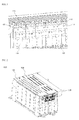
- FIG. 1 is a partial typical view illustrating the side structure of a form including a plurality of stacked battery modules.
- a middle or large-sized battery pack providing high-power, large-capacity electricity, includes a plurality of battery modules 100. Electrode terminals 110 and 120 protrude from one side of each of the battery modules 100. The electrode terminals 110 and 120 are arranged on the same line such that the electrode terminals 110 and 120 are parallel in the stacked direction of the battery modules 100. Also, a screw thread (not shown) is formed at the outer circumference of each of the protruding electrode terminals 110 and 120 so that the conductive connecting member to electrically connect the battery modules 100 to each other can be easily coupled to the electrode terminals 110 and 120.
- FIG. 2 is a perspective view typically illustrating a middle or large-sized battery pack according to an embodiment of the present invention
- FIG. 3 is a typical view illustrating an electrode terminal connecting device of FIG. 2 .
- a middle or large-sized battery pack 900 includes two battery modules 102 and 104 electrically connected to each other via an electrode terminal connection device 300.
- a larger number of battery modules 102 and 104 may be electrically connected to each other so as to power and capacity of the battery pack.
- the electrode terminal connection device 300 includes a conductive connecting member 320 coupled to electrode terminals of the battery modules 102 and 104 to electrically connect the electrode terminals of the battery modules 102 and 104 to each other, a shut-off cutter 310 mounted to the conductive connecting member 320 to shut off the conductive connecting member 320 when impact is applied to the battery pack in the longitudinal direction L of the battery pack, an insulative sheathing member 330 mounted to the conductive connecting member 320 in a state in which the insulative sheathing member 330 surrounds the conductive connecting member 320, the insulative sheathing member 330 being open at the rear thereof excluding regions thereof corresponding to opposite side steps of the conductive connecting member 320, the insulative sheathing member 330 having a side wall protruding a predetermined height from the outer circumference of the conductive connecting member 320, and an insulative cap 340 mounted at the open upper end of the insulative sheathing member 330.
- FIG. 4 is a typical view illustrating the conductive connecting member of FIG. 3
- FIG. 5 is a typical view illustrating the insulative sheathing member and the shut-off cutter of FIG. 3
- FIG. 6 is a typical view illustrating the insulative cap of FIG. 3 .
- the conductive connecting member 320 is configured so that an upper end portion 322 and a lower end portion 324 of a region thereof corresponding to the shut-off cutter 310 having a pointed end 312 are depressed inward to a predetermined depth d.
- the end 312 of the shut-off cutter 310 physically cuts the conductive connecting member 320.
- guide rails 332 and 334 to stably guide the shut-off cutter 310 to the depressed region of the conductive connecting member 320 when impact is applied to the battery pack are formed at the inner top and bottom of the insulative sheathing member 330.
- Hinged protrusions 342 are formed at predetermined portions of the upper end and the lower end of the insulative cap 340 so that the hinged protrusions 342 can be elastically coupled to depressions 336 of the insulative sheathing member 330.
- the hinged protrusions 342 may be separated from the depressions 336 of the insulative sheathing member 330 as needed.
- FIGS. 7 and 8 are typical views illustrating electrode terminal connecting devices according to other embodiments of the present invention.
- an electrode terminal connection device 200 includes a conductive connecting member 210 to electrically connect electrode terminals to each other, an insulative sheathing member 220 mounted to the conductive connecting member 210 in a state in which insulative sheathing member 220 surrounds the conductive connecting member 210 to protect connection regions between the conductive connecting member 210 and the electrode terminals, and a shut-off cutter 310 to shut off the conductive connecting member 210.
- the conductive connecting member 210 is provided with a pair of electrode terminal insertion holes 212 and 213 into which electrode terminals 110 and 120 of a battery module are mechanically coupled. Opposite ends of the conductive connecting member 210 protrude from the outer circumference of the conductive connecting member 210 in a state in which steps a having a predetermined height are formed at the opposite ends of the conductive connecting member 210.
- the insulative sheathing member 220 surrounds the conductive connecting member 210.
- the insulative sheathing member 220 includes a side wall 222 having a predetermined height h with respect to the outer circumference of the conductive connecting member 210.
- the top of the insulative sheathing member 220 is open to achieve easy connection between the electrode terminals 110 and 120 and the conductive connecting member 210.
- the rear of the insulative sheathing member 220 is open excluding regions thereof corresponding to opposite side terminal portions 214 of the conductive connecting member 210.
- an electrode terminal connection device 350 further includes a hollow guide 354 extending downward from an outer part of one side of a sheathing member 352.
- the hollow guide 354 may be used to guide a power cable connected to electrode terminals of an outermost battery module of a middle or large-sized battery pack and a cable (not shown) connected to a service plug.
- the cables may be positioned below the positions of the electrode terminals.
- the hollow guide 354 may be rotated 180 degrees in the horizontal direction so that the cables can be positioned above the positions of the electrode terminals.
- the hollow guide 354 may be formed at the left side of the sheathing member 352 as needed although the hollow guide 354 is shown as being formed at the right side of the sheathing member 352 in the drawing.
- FIGS. 9 and 10 are perspective views typically illustrating middle or large-sized battery packs according to various embodiments of the present invention.
- a middle or large-sized battery pack 400 is configured to have a structure in which a plurality of battery modules 100 each having a cathode terminal and an anode terminal protruding from the same side thereof are stacked. All of the electrode terminals of the battery modules 100 are located at one side of the middle or large-sized battery pack 400.
- An electrode terminal connecting device 200 electrically connects a cathode terminal of a battery module 100 and an anode terminal of an adjacent battery module.
- an electrode terminal connecting device 300 further including a hollow guide to guide a power cable and a cable electrically connected to a service plug 122 is mounted to electrode terminals 116 and 118 of an outermost battery module 102 and electrode terminals 112 and 114 of a middle battery module.
- the cable connected to the service plug 122 extends from the electrode terminals 112 and 114 of the battery module located at the middle of the middle or large-sized battery pack so that the cable can be connected to the service plug 122 via the hollow guide of the electrode terminal connecting device.
- an insulative cap (not shown) is mounted at the open top of the middle or large-sized battery pack 400 to protect connection regions between the electrode terminals 112, 114, 116 and 118 and the electrode terminal connecting devices 200 and 300, thereby preventing the occurrence of a short circuit.
- FIG. 11 is a typical view illustrating a conductive connecting member according to another embodiment of the present invention.
- a conductive connecting member 360 is provided at a region thereof corresponding to a shut-off cutter (not shown) with a slit 362 or a notch 364, at which the shut-off cutter more easily cuts the conductive connecting member when impact is applied to a battery pack in the longitudinal direction of the battery pack.
- the middle or large-sized battery pack includes an electrode terminal connecting device including a conductive connecting member having a specific structure and a shut-off cutter.
- a conductive connecting member having a specific structure
- a shut-off cutter When external force caused due to, for example, vehicle collision is applied to the battery pack in the longitudinal direction of the battery pack, therefore, the conductive connecting member is cut by the shut-off cutter to release the electrical connection between battery modules, thereby lowering risks at the level of the battery pack to the level of the battery modules.
- the electrode terminals connection is isolated from the outside, thereby preventing the occurrence of a short circuit and corrosion due to moisture and thus greatly improving safety of the battery modules.
Landscapes
- Chemical & Material Sciences (AREA)
- Chemical Kinetics & Catalysis (AREA)
- Electrochemistry (AREA)
- General Chemical & Material Sciences (AREA)
- Connection Of Batteries Or Terminals (AREA)
- Battery Mounting, Suspending (AREA)
Abstract
Description
- The present invention relates to a middle or large-sized battery pack including an electrode terminal connecting device, and, more particularly, to a middle or large-sized battery pack having a plurality of electrically connected battery modules, the middle or large-sized battery pack including an electrode terminal connecting device, wherein the electrode terminal connecting device includes a conductive connecting member coupled to electrode terminals of the battery modules to electrically connect the electrode terminals of the battery modules to each other and a shut-off cutter mounted to the conductive connecting member to shut off the circuit of the conductive connecting member when impact is applied to the battery pack in the longitudinal direction of the battery pack.
- Recently, a secondary battery, which can be charged and discharged, has been widely used as an energy source for wireless mobile devices. Also, the secondary battery has attracted considerable attention as a power source for electric vehicles (EV), hybrid electric vehicles (HEV), and plug-in hybrid electric vehicles (Plug-in HEV), which have been developed to solve problems, such as air pollution, caused by existing gasoline and diesel vehicles using fossil fuels.
- Small-sized mobile devices use one or several battery cells for each device. On the other hand, middle or large-sized devices, such as vehicles, use a middle or large-sized battery module having a plurality of battery cells electrically connected to one another because high power and large capacity are necessary for the middle or large-sized devices.
- Generally, a plurality of unit cells are mounted in a cartridge which connects the unit cells in series and/or in parallel to each other, and a plurality of cartridges are electrically connected to each other, thereby manufacturing a battery module. According to circumstances, two or more battery modules are electrically connected to each other, thereby manufacturing a middle or large-sized battery pack or system providing higher power.
- Meanwhile, such a middle or large-sized battery pack exhibits high safety with respect to deformation of the battery pack in the thickness thereof but low safety with respect to deformation of the battery pack in the electrode terminal direction of the battery cells.
- In particular, in a case in which a plurality of battery cells is electrically connected in series to each other as in a middle or large-sized battery pack, a short circuit occurs at electrode terminal regions of a battery module when external force caused due to, for example, vehicle collision is applied to the battery pack with the result the battery pack may catch fire or explode.
- Consequently, there is a high necessity for a middle or large-sized battery pack including an electrode terminal connecting device that is capable of shutting off an electrode terminal connection region of a battery module through a simple structure when external force is applied to the battery pack, thereby fundamentally solving the above problems.
- Therefore, the present invention has been made to solve the above problems, and other technical problems that have yet to be resolved.
- Specifically, it is an object of the present invention to provide a middle or large-sized battery pack including an electrode terminal connecting device including a conductive connecting member having a specific structure and a shut-off cutter wherein, when external force caused due to, for example, vehicle collision is applied to the battery pack in the longitudinal direction of the battery pack, the conductive connecting member is cut by the shut-off cutter to release the electrical connection between battery modules, thereby lowering risks at the level of the battery pack to the level of the battery modules.
- In accordance with one aspect of the present invention, the above and other objects can be accomplished by the provision of a middle or large-sized battery pack having a plurality of electrically connected battery modules, the middle or large-sized battery pack including an electrode terminal connecting device, wherein the electrode terminal connecting device includes a conductive connecting member coupled to electrode terminals of the battery modules to electrically connect the electrode terminals of the battery modules to each other and a shut-off cutter mounted to the conductive connecting member to shut off the circuit of the conductive connecting member when impact is applied to the battery pack in the longitudinal direction of the battery pack.
- As described above, the a middle or large-sized battery pack according to the present invention includes the electrode terminal connecting device, which includes the conductive connecting member to electrically connect the electrode terminals to each other and the shut-off cutter to shut off the circuit of the conductive connecting member. When external force caused due to, for example, vehicle collision is applied to the battery pack in the longitudinal direction of the battery pack, therefore, the conductive connecting member is easily cut by the shut-off cutter to release the electrical connection between the battery modules of the battery pack, thereby greatly improving safety of the battery pack.
- Also, the shut-off cutter having the simple structure which operates mechanically is added to the existing conductive connecting member without the provision of an additional component, thereby securing safety of the battery pack during a collision as compared with a conventional middle or large-sized battery pack.
- In addition, the electrode terminal connecting device does not use an electrical signal but submersion load of an external structure during a collision, thereby achieving very high operational reliability.
- The shut-off circuit may be achieved by the shut-off cutter physically cutting the conductive connecting member, for example, when impact is applied to the battery pack in the longitudinal direction of the battery pack.
- That is, external force applied to the battery pack in the longitudinal direction of the battery pack moves the shut-off cutter to the conductive connecting member, and the shut-off cutter cuts a portion of the conductive connecting member connecting the electrode terminals of the battery modules to release the electrical connection between the battery modules. Alternatively, the battery pack may move to the shut-off cutter to achieve desired cutting of the conductive connecting member.
- The structure of the shut-off cutter is not particularly restricted so long as the shut-off cutter can easily cut the conductive connecting member in a physical manner. For example, the shut-off cutter may include a pointed end. In this case, the conductive connecting member is easily cut by the pointed end of the shut-off cutter.
- As another example, the shut-off cutter may be made of an insulative material to easily cut the conductive connecting member without electrical spark. Alternatively, the shut-off cutter may include a main body made of an insulative material and a metal pointed end provided at an end of the main body.
- In a case in which the shut-off cutter includes a main body made of an insulative material and a metal pointed end provided at an end of the main body as described above, the conductive connecting member may be easily cut by the metal pointed end. Electrical flow occurring at the contact surface of the conductive connecting member during cutting may be interrupted by the main body made of the insulative material.
- The insulative material is not particularly restricted. For example, the insulative material may include ceramic or plastic. The metal material is not also particularly restricted. For example, the metal material may include iron, nickel, aluminum, copper or alloys thereof.
- Meanwhile, as previously mentioned, it is necessary for the conductive connecting member to be reliably cut by the shut-off cutter, thereby securing safety of the battery pack when impact is applied to the battery pack in the longitudinal direction of the battery pack. In a preferred example, the conductive connecting member may be configured so that an upper end portion and a lower end portion of a region thereof corresponding to the shut-off cutter are depressed inward to a predetermined depth so as to achieve reliable cutting of the conductive connecting member.
- Specifically, the upper end portion and the lower end portion of the conductive connecting member are depressed inward with the result that the size of the region to be cut is decreased. Consequently, the shut-off cutter moves to the conductive connecting member due to external impact to easily cut the depressed region of the conductive connecting member.
- As a modification of the above structure, the conductive connecting member may be provided at a region thereof corresponding to the shut-off cutter with a notch or a slit, at which the shut-off cutter easily cuts the conductive connecting member.
- The conductive connecting member is a member provided to achieve electrical connection between the electrode terminals. Preferably, the conductive connecting member is formed of a plate-shaped metal member having electrode terminals insertion holes formed at positions corresponding to the electrode terminals of the battery module so that the electrode terminals of the battery module are inserted through the respective electrode terminals insertion holes. The conductive connecting member has a length sufficient to electrically connect two or more electrode terminals to each other, the conductive connecting member is provided at positions thereof corresponding to the distance between the electrode terminals with electrode terminal insertion holes, and each of the electrode terminal insertion holes has an inner diameter greater, preferably, in the longitudinal direction of the battery pack so that the electrode terminals can be easily inserted through the electrode terminal insertion holes even when a positional deviation between the electrode terminals occurs.
- In a preferred example, the protrusion of each of the electrode terminals is configured in a bolt structure formed a screw thread formed at the outer circumference thereof, and a predetermined fastening member may be configured in a nut structure having a screw thread corresponding to the outer circumference of a corresponding one of the electrode terminals so that the fastening member is coupled to the corresponding one of the electrode terminals. The electrode terminals each configured in the bolt structure are stably coupled to fastening members each configured in the nut structure in a state in which the electrode terminals are inserted through the electrode terminal insertion holes of the conductive connecting member.
- Preferably, the electrode terminal connecting device further includes an insulative sheathing member mounted to the conductive connecting member in a state in which the insulative sheathing member surrounds the conductive connecting member, the insulative sheathing member being open at a rear thereof excluding regions thereof corresponding to opposite side steps of the conductive connecting member, the insulative sheathing member having a side wall protruding a predetermined height from an outer circumference of the conductive connecting member.
- In the electrode terminal connecting device as described above, therefore, the coupling of the conductive connecting member to the electrode terminals of the battery module is achieved by the conductive connecting member having the specific structure and the insulative sheathing member, and, at the same time, the coupling between the conductive connecting member and the insulative sheathing member is achieved. Also, the electrical connection region between the electrode terminals is protected by the insulative sheathing member, thereby preventing the occurrence of a short circuit and thus greatly improving safety at the electrical connection region between the electrode terminals.
- As a concrete example of the above structure, the conductive connecting member is configured so that opposite ends of the conductive connecting member protrude from the conductive connecting member in a state in which steps a having a predetermined height are formed at the opposite ends of the conductive connecting member, and the insulative sheathing member is provided at the inside thereof with a coupling member, having a height corresponding to the protruding thickness of the conductive connecting member and configured to have a downwardly tapered structure, to achieve secure coupling between the conductive connecting member and the insulative sheathing member. Consequently, the opposite ends of the conductive connecting member are stably coupled to the insulative sheathing member by the coupling member configured to have the downwardly tapered structure.
- Specifically, when the conductive connecting member is inserted into the insulative sheathing member in a state in which the insulative sheathing member is located in the electrode terminals of the battery module, the coupling member configured to have the downwardly tapered structure allows the conductive connecting member to be inserted into the inside of the insulative sheathing member. After insertion, however, the coupling member configured to have the downwardly tapered structure prevents the conductive connecting member from being separated from the inside of the insulative sheathing member.
- In the above structure, the insulative sheathing member may be provided at the inner top and/or bottom thereof with a guide rail to guide movement of the shut-off cutter when impact is applied to the battery pack. The guide rail stably guides the shut-off cutter to a desired region to be cut of the conductive connecting member, which is preferable.
- In another preferred example, the insulative sheathing member may be open at the top thereof, and the middle or large-sized battery pack may further include an insulative cap mounted at the open top of the insulative sheathing member. Consequently, the electrical connection region of the insulative sheathing member is covered by the insulative cap with the result that electric current flowing in the conductive connecting member is completely isolated from the outside. Also, the insulative cap protects the connection region between the electrode terminals of the battery module and the conductive connecting member from external impact and, at the same time, prevents introduction of foreign matter and permeation of moisture.
- The insulative cap may be configured in various structures. For example, the insulative cap may be mounted to the insulative sheathing member in a sliding manner. Also, the insulative cap may be disposed in tight contact with the upper end of the insulative sheathing member while elastically deforming the insulative sheathing member by a small width. In addition, the insulative cap may be coupled to one side of the insulative sheathing member in a hinged structure or in a fastened manner based on a predetermined coupling structure. Preferably, the insulative cap is made of the same insulative material as the insulative sheathing member. However, the insulative cap may be made of a different insulative material than the insulative sheathing member.
- The structure of the shut-off cutter is not particularly restricted so long as the shut-off cutter is mounted in the insulative sheathing member to easily cut the conductive connecting member when external impact is applied to the battery pack. For example, the shut-off cutter may be mounted in the insulative sheathing member in a state in which the shut-off cutter is separated from the insulative cap. Alternatively, the shut-off cutter may be mounted in the insulative sheathing member in a state in which the shut-off cutter is coupled to the insulative cap.
- Meanwhile, in a middle or large-sized battery pack configured to have a structure in which a plurality of battery modules are stacked and electrically connected to each other to provide high power and large capacity, electrode terminals of an outermost battery module are connected to an external device requiring power from the battery module via a linear connecting member, such as a power cable. Also, it may be necessary to locate a service plug on a path of a cathode or anode circuit so as to manually cut off electricity when it is necessary to confirm the operating state of the battery module as needed and to repair the battery module.
- At this time, the insulative sheathing member mounted the electrode terminals of the outermost battery module or the battery module requiring to be electrically connected to the service plug, among the connecting members to electrically connect the respective battery modules to each other, further includes a guide part to guide wiring of the linear connecting member connected to the respective electrode terminals.
- Consequently, the insulative sheathing member may be provided at the outer part of one side thereof with a guide part to easily achieve installation and wiring of another linear connecting member. In this case, the guide part may be configured to have a structure in which a hollow guide extends from a position corresponding to the electrode terminals of the battery modules. The guide part may extend upward or downward from a position corresponding to the electrode terminals of the battery modules based on the wiring position of the desired linear connecting member.
- According to circumstances, a region of a battery module case corresponding to the electrode terminals may be configured to have a structure in which a region of the battery module case corresponding to the shut-off cutter is depressed inward so that the conductive connecting member is easily cut by the shut-off cutter when impact is applied to the battery pack in the longitudinal direction of the battery pack.
- The battery pack may be configured to have a structure in which a plurality of battery modules, each having a cathode terminal and an anode terminal protruding from the same side thereof, is stacked. That is, in a case in which the cathode terminal and the anode terminal are formed at the same side of each of the battery modules, the size of a space caused due to the protrusion regions of the electrode terminals is reduced as compared with a case in which the cathode terminal and the anode terminal are formed at different sides of each of the battery modules. Consequently, it is possible to configure the battery pack in a more compact structure.
- In this case, the electrode terminals of the battery modules may be arranged on the same line, the electrode terminal connecting device may be mounted at electrical connection region between the electrode terminals, and a plurality of insulative cap may be mounted to simultaneously cover open tops of a plurality of electrode terminal connecting devices.
- As an example, the insulative cap may be configured in an integrated structure or in a separate structure having two insulative cap parts. Also, the insulative cap may be configured in an individual structure to cover the respective insulative sheathing members. Of course, one or more insulative caps may be provided based on desired regions to be covered of the electrode terminal connecting device.
- In the middle or large-sized battery pack providing high power and large capacity, as previously described, a service plug is needed to manually cut off electricity when it is necessary to confirm the operating state of the battery module and to repair the battery module or when emergency requiring a shut-off circuit at an external device, such as a vehicle, occurs.
- Consequently, the middle or large-sized battery pack according to the present invention may be configured to have a structure in which a service plug is mounted at one or more electrical connection regions between stacked battery modules to achieve a shut-off circuit.
- In accordance with another aspect of the present invention, there is provided an electrode terminal connecting device to electrically connect a plurality of battery modules to each other. Specifically, the electrode terminal connecting device includes a conductive connecting member coupled to electrode terminals of the battery modules to electrically connect the electrode terminals of the battery modules to each other, the conductive connecting member being provided at opposite sides thereof with steps, a shut-off cutter mounted to the outside of the conductive connecting member to shut off the circuit of the conductive connecting member when impact is applied to the battery pack in the longitudinal direction of the battery pack, and an insulative sheathing member mounted to the conductive connecting member in a state in which the insulative sheathing member surrounds the conductive connecting member, the insulative sheathing member being open at the rear thereof excluding regions thereof corresponding to the opposite side steps of the conductive connecting member, the insulative sheathing member having a side wall protruding a predetermined height from the outer circumference of the conductive connecting member.
- Since the electrode terminal connecting device includes the conductive connecting member, the shut-off cutter and the insulative sheathing member, as described above, the conductive connecting member is easily cut by the shut-off cutter when impact is applied to the battery pack in the longitudinal direction of the battery pack. Also, it is possible to connect the battery modules in series and/or in parallel to each other. Consequently, it is possible to freely design the battery pack so that the battery pack provides desired power and capacity.
- The above and other objects, features and other advantages of the present invention will be more clearly understood from the following detailed description taken in conjunction with the accompanying drawings, in which:
-
FIG. 1 is a partial typical view illustrating the side structure of a form including a plurality of stacked battery modules; -
FIG. 2 is a perspective view illustrating a middle or large-sized battery pack according to an embodiment of the present invention; -
FIG. 3 is a typical view illustrating an electrode terminal connecting device ofFIG. 2 ; -
FIG. 4 is a typical view illustrating a conductive connecting member ofFIG. 3 ; -
FIG. 5 is a typical view illustrating an insulative sheathing member and a shut-off cutter ofFIG. 3 ; -
FIG. 6 is a typical view illustrating an insulative cap ofFIG. 3 ; -
FIGS. 7 and8 are typical views illustrating electrode terminal connecting devices according to other embodiments of the present invention; -
FIGS. 9 and10 are perspective views illustrating middle or large-sized battery packs according to various embodiments of the present invention; and -
FIG. 11 is a typical view illustrating a conductive connecting member according to another embodiment of the present invention. - Now, preferred embodiments of the present invention will be described in detail with reference to the accompanying drawings. It should be noted, however, that the scope of the present invention is not limited by the illustrated embodiments.
-
FIG. 1 is a partial typical view illustrating the side structure of a form including a plurality of stacked battery modules. - Referring to
FIG. 1 , a middle or large-sized battery pack, providing high-power, large-capacity electricity, includes a plurality ofbattery modules 100.Electrode terminals battery modules 100. Theelectrode terminals electrode terminals battery modules 100. Also, a screw thread (not shown) is formed at the outer circumference of each of the protrudingelectrode terminals battery modules 100 to each other can be easily coupled to theelectrode terminals -
FIG. 2 is a perspective view typically illustrating a middle or large-sized battery pack according to an embodiment of the present invention, andFIG. 3 is a typical view illustrating an electrode terminal connecting device ofFIG. 2 . - Referring to these drawings, a middle or large-
sized battery pack 900 includes twobattery modules terminal connection device 300. A larger number ofbattery modules - The electrode
terminal connection device 300 includes a conductive connectingmember 320 coupled to electrode terminals of thebattery modules battery modules off cutter 310 mounted to the conductive connectingmember 320 to shut off the conductive connectingmember 320 when impact is applied to the battery pack in the longitudinal direction L of the battery pack, aninsulative sheathing member 330 mounted to the conductive connectingmember 320 in a state in which theinsulative sheathing member 330 surrounds the conductive connectingmember 320, theinsulative sheathing member 330 being open at the rear thereof excluding regions thereof corresponding to opposite side steps of the conductive connectingmember 320, theinsulative sheathing member 330 having a side wall protruding a predetermined height from the outer circumference of the conductive connectingmember 320, and aninsulative cap 340 mounted at the open upper end of theinsulative sheathing member 330. -
FIG. 4 is a typical view illustrating the conductive connecting member ofFIG. 3 ,FIG. 5 is a typical view illustrating the insulative sheathing member and the shut-off cutter ofFIG. 3 , andFIG. 6 is a typical view illustrating the insulative cap ofFIG. 3 . - Referring to these drawings together with
FIG. 2 , the conductive connectingmember 320 is configured so that anupper end portion 322 and alower end portion 324 of a region thereof corresponding to the shut-off cutter 310 having apointed end 312 are depressed inward to a predetermined depth d. When impact is applied to the battery pack in the longitudinal direction L of the battery pack, therefore, theend 312 of the shut-off cutter 310 physically cuts the conductive connectingmember 320. - Also,
guide rails off cutter 310 to the depressed region of the conductive connectingmember 320 when impact is applied to the battery pack are formed at the inner top and bottom of theinsulative sheathing member 330. - Hinged
protrusions 342 are formed at predetermined portions of the upper end and the lower end of theinsulative cap 340 so that the hingedprotrusions 342 can be elastically coupled todepressions 336 of theinsulative sheathing member 330. The hingedprotrusions 342 may be separated from thedepressions 336 of theinsulative sheathing member 330 as needed. -
FIGS. 7 and8 are typical views illustrating electrode terminal connecting devices according to other embodiments of the present invention. - Referring to
FIG. 7 together withFIG. 1 , an electrodeterminal connection device 200 includes a conductive connectingmember 210 to electrically connect electrode terminals to each other, aninsulative sheathing member 220 mounted to the conductive connectingmember 210 in a state in which insulative sheathingmember 220 surrounds the conductive connectingmember 210 to protect connection regions between the conductive connectingmember 210 and the electrode terminals, and a shut-off cutter 310 to shut off the conductive connectingmember 210. - The conductive connecting
member 210 is provided with a pair of electrode terminal insertion holes 212 and 213 into whichelectrode terminals member 210 protrude from the outer circumference of the conductive connectingmember 210 in a state in which steps a having a predetermined height are formed at the opposite ends of the conductive connectingmember 210. - The
insulative sheathing member 220 surrounds the conductive connectingmember 210. Theinsulative sheathing member 220 includes aside wall 222 having a predetermined height h with respect to the outer circumference of the conductive connectingmember 210. The top of theinsulative sheathing member 220 is open to achieve easy connection between theelectrode terminals member 210. Also, the rear of theinsulative sheathing member 220 is open excluding regions thereof corresponding to oppositeside terminal portions 214 of the conductive connectingmember 210. - A pair of
coupling members 226, having a height approximately equivalent to the thickness of the conductive connectingmember 210 and configured to have a downwardly tapered structure, protrudes from the inside 218 of theinsulative sheathing member 220. Consequently, the conductive connectingmember 210, which is formed in the shape of a plate, is inserted into theinsulative sheathing member 220 through the open upper end of theinsulative sheathing member 220, and the opposite ends of the conductive connectingmember 210 are coupled to thecoupling members 226. After the coupling between the opposite ends of the conductive connectingmember 210 and thecoupling members 226, the conductive connectingmember 210 is prevented from being separated upward by virtue of the tapered structure of each of thecoupling members 226. - Referring to
FIG. 8 , an electrodeterminal connection device 350 further includes ahollow guide 354 extending downward from an outer part of one side of asheathing member 352. Thehollow guide 354 may be used to guide a power cable connected to electrode terminals of an outermost battery module of a middle or large-sized battery pack and a cable (not shown) connected to a service plug. - In a case in which the
hollow guide 354 is located in the downward direction as shown in the drawing, the cables may be positioned below the positions of the electrode terminals. On the other hand, thehollow guide 354 may be rotated 180 degrees in the horizontal direction so that the cables can be positioned above the positions of the electrode terminals. Also, thehollow guide 354 may be formed at the left side of thesheathing member 352 as needed although thehollow guide 354 is shown as being formed at the right side of thesheathing member 352 in the drawing. -
FIGS. 9 and10 are perspective views typically illustrating middle or large-sized battery packs according to various embodiments of the present invention. - Referring to these drawings, a middle or large-
sized battery pack 400 is configured to have a structure in which a plurality ofbattery modules 100 each having a cathode terminal and an anode terminal protruding from the same side thereof are stacked. All of the electrode terminals of thebattery modules 100 are located at one side of the middle or large-sized battery pack 400. An electrodeterminal connecting device 200 electrically connects a cathode terminal of abattery module 100 and an anode terminal of an adjacent battery module. - Referring to
FIG. 10 , an electrodeterminal connecting device 300 further including a hollow guide to guide a power cable and a cable electrically connected to aservice plug 122 is mounted toelectrode terminals outermost battery module 102 andelectrode terminals - That is, the cable connected to the
service plug 122 extends from theelectrode terminals service plug 122 via the hollow guide of the electrode terminal connecting device. - Also, an insulative cap (not shown) is mounted at the open top of the middle or large-
sized battery pack 400 to protect connection regions between theelectrode terminals terminal connecting devices -
FIG. 11 is a typical view illustrating a conductive connecting member according to another embodiment of the present invention. - Referring to
FIG. 11 , a conductive connectingmember 360 is provided at a region thereof corresponding to a shut-off cutter (not shown) with aslit 362 or anotch 364, at which the shut-off cutter more easily cuts the conductive connecting member when impact is applied to a battery pack in the longitudinal direction of the battery pack. - As is apparent from the above description, the middle or large-sized battery pack according to the present invention includes an electrode terminal connecting device including a conductive connecting member having a specific structure and a shut-off cutter. When external force caused due to, for example, vehicle collision is applied to the battery pack in the longitudinal direction of the battery pack, therefore, the conductive connecting member is cut by the shut-off cutter to release the electrical connection between battery modules, thereby lowering risks at the level of the battery pack to the level of the battery modules.
- Also, it is possible to stably and easily achieve electrical connection between the electrode terminals at the electrode terminal connection region in a simple structure through the use of the electrode terminal connecting device. Consequently, it is possible to lower manufacturing cost and to easily achieve installation and wiring of a linear member for electrical connection with an external device or an internal device.
- Furthermore, the electrode terminals connection is isolated from the outside, thereby preventing the occurrence of a short circuit and corrosion due to moisture and thus greatly improving safety of the battery modules.
- Although the preferred embodiments of the present invention have been disclosed for illustrative purposes, those skilled in the art will appreciate that various modifications, additions and substitutions are possible, without departing from the scope and spirit of the invention as disclosed in the accompanying claims.
Claims (19)
- A middle or large-sized battery pack having a plurality of electrically connected battery modules, the middle or large-sized battery pack comprising an electrode terminal connecting device, wherein the electrode terminal connecting device comprises:a conductive connecting member coupled to electrode terminals of the battery modules to electrically connect the electrode terminals of the battery modules to each other; anda shut-off cutter mounted to the conductive connecting member to shut off the circuit of the conductive connecting member when impact is applied to the battery pack in a longitudinal direction of the battery pack.
- The middle or large-sized battery pack according to claim 1, wherein the shut-off circuit is achieved by the shut-off cutter physically cutting the conductive connecting member when impact is applied to the battery pack in the longitudinal direction of the battery pack.
- The middle or large-sized battery pack according to claim 1, wherein the shut-off cutter comprises a pointed end.
- The middle or large-sized battery pack according to claim 1, wherein the shut-off cutter is made of an insulative material or comprises a main body made of an insulative material and a metal pointed end provided at an end of the main body.
- The middle or large-sized battery pack according to claim 1, wherein the conductive connecting member is configured so that an upper end portion and a lower end portion of a region thereof corresponding to the shut-off cutter are depressed inward to a predetermined depth.
- The middle or large-sized battery pack according to claim 1, wherein the conductive connecting member is provided at a region thereof corresponding to the shut-off cutter with a notch or a slit, at which the shut-off cutter easily cuts the conductive connecting member.
- The middle or large-sized battery pack according to claim 1, wherein the conductive connecting member has a length sufficient to electrically connect two or more electrode terminals to each other, the conductive connecting member is provided at positions thereof corresponding to a distance between the electrode terminals with electrode terminal insertion holes, and each of the electrode terminal insertion holes has an inner diameter greater in the longitudinal direction of the battery pack so that the electrode terminals can be easily inserted through the electrode terminal insertion holes even when a positional deviation between the electrode terminals occurs.
- The middle or large-sized battery pack according to claim 1, wherein the electrode terminal connecting device further comprises an insulative sheathing member mounted to the conductive connecting member in a state in which the insulative sheathing member surrounds the conductive connecting member, the insulative sheathing member being open at a rear thereof excluding regions thereof corresponding to opposite side steps of the conductive connecting member, the insulative sheathing member having a side wall protruding a predetermined height from an outer circumference of the conductive connecting member.
- The middle or large-sized battery pack according to claim 8, wherein the conductive connecting member is configured so that opposite ends of the conductive connecting member protrude from the conductive connecting member in a state in which steps a having a predetermined height are formed at the opposite ends of the conductive connecting member, and the insulative sheathing member is provided at an inside thereof with a coupling member, having a height corresponding to a protruding thickness of the conductive connecting member and configured to have a downwardly tapered structure, to achieve secure coupling between the conductive connecting member and the insulative sheathing member.
- The middle or large-sized battery pack according to claim 8, wherein the insulative sheathing member is provided at an inner top and/or bottom thereof with a guide rail to guide movement of the shut-off cutter when impact is applied to the battery pack.
- The middle or large-sized battery pack according to claim 8, wherein the insulative sheathing member is open at a top thereof, and the middle or large-sized battery pack further comprises an insulative cap mounted at the open top of the insulative sheathing member.
- The middle or large-sized battery pack according to claim 11, wherein the insulative cap is coupled to the insulative sheathing member in a hinged structure or in a fastened manner.
- The middle or large-sized battery pack according to claim 11, wherein the shut-off cutter is mounted in the insulative sheathing member in a state in which the shut-off cutter is separated from the insulative cap or in a state in which the shut-off cutter is coupled to the insulative cap.
- The middle or large-sized battery pack according to claim 8, wherein the insulative sheathing member is provided at an outer part of one side thereof with a guide part to easily achieve installation and wiring of another linear connecting member.
- The middle or large-sized battery pack according to claim 14, wherein the guide part is configured to have a structure in which a hollow guide extends upward or downward from a position corresponding to the electrode terminals of the battery modules.
- The middle or large-sized battery pack according to claim 1, wherein a region of a battery module case corresponding to the electrode terminals is configured to have a structure in which a region of the battery module case corresponding to the shut-off cutter is depressed inward so that the conductive connecting member is easily cut by the shut-off cutter when impact is applied to the battery pack in the longitudinal direction of the battery pack.
- The middle or large-sized battery pack according to claim 1, wherein the battery pack is configured to have a structure in which a plurality of battery modules, each having a cathode terminal and an anode terminal protruding from the same side thereof, is stacked.
- The middle or large-sized battery pack according to claim 1, wherein the electrode terminals of the battery modules are arranged on the same line, the electrode terminal connecting device is mounted at electrical connection region between the electrode terminals, and a plurality of insulative cap is mounted to simultaneously cover open tops of a plurality of electrode terminal connecting devices.
- An electrode terminal connecting device to electrically connect a plurality of battery modules to each other, wherein the electrode terminal connecting device comprises:a conductive connecting member coupled to electrode terminals of the battery modules to electrically connect the electrode terminals of the battery modules to each other, the conductive connecting member being provided at opposite sides thereof with steps;a shut-off cutter mounted to an outside of the conductive connecting member to shut off the circuit of the conductive connecting member when impact is applied to the battery pack in a longitudinal direction of the battery pack; andan insulative sheathing member mounted to the conductive connecting member in a state in which the insulative sheathing member surrounds the conductive connecting member, the insulative sheathing member being open at a rear thereof excluding regions thereof corresponding to the opposite side steps of the conductive connecting member, the insulative sheathing member having a side wall protruding a predetermined height from an outer circumference of the conductive connecting member.
Applications Claiming Priority (2)
| Application Number | Priority Date | Filing Date | Title |
|---|---|---|---|
| KR1020080100624A KR101082862B1 (en) | 2008-10-14 | 2008-10-14 | Battery Pack Containing Electrode Terminal Connecting Device |
| PCT/KR2009/005404 WO2010044552A2 (en) | 2008-10-14 | 2009-09-23 | Medium or large battery pack including electrode connection device |
Publications (3)
| Publication Number | Publication Date |
|---|---|
| EP2337119A2 true EP2337119A2 (en) | 2011-06-22 |
| EP2337119A4 EP2337119A4 (en) | 2014-08-13 |
| EP2337119B1 EP2337119B1 (en) | 2018-05-09 |
Family
ID=42107011
Family Applications (1)
| Application Number | Title | Priority Date | Filing Date |
|---|---|---|---|
| EP09820702.0A Active EP2337119B1 (en) | 2008-10-14 | 2009-09-23 | Medium or large battery pack including electrode connection device |
Country Status (7)
| Country | Link |
|---|---|
| US (1) | US9246152B2 (en) |
| EP (1) | EP2337119B1 (en) |
| JP (1) | JP5651875B2 (en) |
| KR (1) | KR101082862B1 (en) |
| CN (1) | CN102165630B (en) |
| RU (1) | RU2454754C1 (en) |
| WO (1) | WO2010044552A2 (en) |
Cited By (6)
| Publication number | Priority date | Publication date | Assignee | Title |
|---|---|---|---|---|
| JP2013037988A (en) * | 2011-08-10 | 2013-02-21 | Auto Network Gijutsu Kenkyusho:Kk | Bus bar cover and bus bar provided with cover |
| CN103165844A (en) * | 2011-12-14 | 2013-06-19 | 比亚迪股份有限公司 | Battery connector and battery pack with same |
| EP2608290A1 (en) * | 2011-12-23 | 2013-06-26 | Samsung SDI Co., Ltd. | Battery module |
| KR20140010234A (en) | 2012-07-16 | 2014-01-24 | 에스케이이노베이션 주식회사 | Battery pack |
| KR20140011664A (en) | 2012-07-18 | 2014-01-29 | 에스케이이노베이션 주식회사 | Battery pack |
| DE102014222383A1 (en) | 2014-11-03 | 2016-05-04 | Robert Bosch Gmbh | Battery with improved safety |
Families Citing this family (22)
| Publication number | Priority date | Publication date | Assignee | Title |
|---|---|---|---|---|
| JP5476603B2 (en) * | 2010-09-30 | 2014-04-23 | パナソニック株式会社 | Battery pack for vehicles |
| US8642206B2 (en) | 2010-11-04 | 2014-02-04 | Samsung Sdi Co., Ltd. | Battery module |
| US8852789B2 (en) | 2010-11-04 | 2014-10-07 | Samsung Sdi Co., Ltd. | Battery module having battery cell holder |
| KR101223519B1 (en) | 2010-11-05 | 2013-01-17 | 로베르트 보쉬 게엠베하 | Battery module |
| KR101191659B1 (en) | 2010-11-05 | 2012-10-17 | 에스비리모티브 주식회사 | Battery module |
| KR101201742B1 (en) | 2010-11-05 | 2012-11-15 | 에스비리모티브 주식회사 | Battery module |
| KR101201740B1 (en) | 2010-11-12 | 2012-11-15 | 에스비리모티브 주식회사 | Battery module |
| US20130011710A1 (en) * | 2011-01-07 | 2013-01-10 | Keisuke Naito | Battery pack |
| KR101307386B1 (en) * | 2011-06-08 | 2013-09-11 | 주식회사 엘지화학 | Safety Device for Battery Pack |
| US9105912B2 (en) * | 2012-05-21 | 2015-08-11 | Tyco Electronics Corporation | Boltless battery cell connection |
| KR101401477B1 (en) * | 2012-08-02 | 2014-05-29 | 주식회사 엘지화학 | Connecting element for secondary battery, Battery module and Battery pack comprising the same |
| KR101619603B1 (en) * | 2014-08-13 | 2016-05-10 | 현대자동차주식회사 | Safety apparatus for battery of vehicle and operating method for the same |
| JP6235529B2 (en) * | 2015-05-25 | 2017-11-22 | トヨタ自動車株式会社 | Electric vehicle and battery pack |
| JP6413931B2 (en) * | 2015-05-29 | 2018-10-31 | 豊田合成株式会社 | Conduction interruption device |
| CN107093687A (en) * | 2017-05-26 | 2017-08-25 | 江苏银基烯碳能源科技有限公司 | A kind of battery module structure |
| KR102256605B1 (en) * | 2017-07-06 | 2021-05-26 | 주식회사 엘지에너지솔루션 | Battery module and battery pack including the same |
| CN208674174U (en) * | 2018-09-26 | 2019-03-29 | 宁德时代新能源科技股份有限公司 | battery module |
| CN111162239A (en) * | 2020-01-22 | 2020-05-15 | 江门市大长江集团有限公司 | Transport means, battery case and power plug connector thereof |
| JP7463768B2 (en) * | 2020-03-03 | 2024-04-09 | マツダ株式会社 | Lithium-ion battery device |
| CN114520400A (en) * | 2020-11-20 | 2022-05-20 | 比亚迪股份有限公司 | Smart Connecting Sheets, Battery Packs and Vehicles |
| JP7289862B2 (en) * | 2021-03-01 | 2023-06-12 | プライムプラネットエナジー&ソリューションズ株式会社 | battery pack |
| CN118841380B (en) * | 2024-06-26 | 2025-09-30 | 华为数字能源技术有限公司 | Power modules and power conversion devices |
Family Cites Families (25)
| Publication number | Priority date | Publication date | Assignee | Title |
|---|---|---|---|---|
| US5120617A (en) * | 1989-12-13 | 1992-06-09 | Cameron Robert W | Vehicle battery having integral safety switch |
| US5804770A (en) * | 1995-09-19 | 1998-09-08 | Sumitomo Wiring Systems, Ltd. | Cover equipped electrical connection device and a cover for an electrical connection device |
| JP3882267B2 (en) * | 1997-05-29 | 2007-02-14 | 新神戸電機株式会社 | Battery power supply |
| JPH11353997A (en) | 1998-06-08 | 1999-12-24 | Yazaki Corp | Current interrupt device |
| JP4220649B2 (en) * | 1999-06-10 | 2009-02-04 | パナソニック株式会社 | Assembled battery |
| JP3887145B2 (en) * | 2000-05-25 | 2007-02-28 | 矢崎総業株式会社 | Battery cover shock absorption structure |
| JP4918186B2 (en) * | 2000-07-17 | 2012-04-18 | 三菱重工業株式会社 | Secondary battery module |
| DE60307750T2 (en) * | 2002-05-08 | 2006-12-14 | Nissan Motor Co., Ltd., Yokohama | Secondary cell module and method for its production |
| US20040041682A1 (en) * | 2002-08-29 | 2004-03-04 | Pasha Brian D. | Battery circuit disconnect device |
| JP2004159439A (en) * | 2002-11-07 | 2004-06-03 | Toyota Motor Corp | Power shut-off device |
| DE102004008120A1 (en) | 2003-02-26 | 2004-11-25 | Dynamit Nobel Ais Gmbh Automotive Ignition Systems | Pyromechanical disconnect device with specially shaped conductor rail |
| EP1469564B1 (en) * | 2003-04-17 | 2012-12-05 | Autoliv Development AB | Pyrotechnical battery terminal |
| US7123124B2 (en) * | 2003-10-17 | 2006-10-17 | Special Devices, Inc. | Pyrotechnic circuit breaker |
| KR100875606B1 (en) * | 2004-12-24 | 2008-12-24 | 주식회사 엘지화학 | Secondary battery module |
| KR100876456B1 (en) | 2004-12-24 | 2008-12-29 | 주식회사 엘지화학 | Detachable connecting member and method for manufacturing secondary battery module using the same |
| PL2590242T3 (en) * | 2004-12-24 | 2020-01-31 | Lg Chem, Ltd. | Method and device for improving the performance of battery module by leveling voltage |
| KR100868255B1 (en) | 2005-04-19 | 2008-11-11 | 주식회사 엘지화학 | Terminal connector |
| KR100903185B1 (en) | 2005-05-02 | 2009-06-17 | 주식회사 엘지화학 | Improved medium and large battery packs with improved safety |
| KR100881641B1 (en) | 2005-05-10 | 2009-02-04 | 주식회사 엘지화학 | Medium to large battery packs with safety system |
| JP5061430B2 (en) * | 2005-07-08 | 2012-10-31 | 日産自動車株式会社 | Battery module |
| JP4902204B2 (en) * | 2006-01-13 | 2012-03-21 | 三洋電機株式会社 | Sealed secondary battery with bolt type terminal and assembled battery using the same |
| JP5037308B2 (en) | 2006-11-21 | 2012-09-26 | 日立ビークルエナジー株式会社 | Secondary battery module |
| US8276695B2 (en) * | 2007-12-25 | 2012-10-02 | Byd Co. Ltd. | Battery electrode sheet |
| US20090159354A1 (en) * | 2007-12-25 | 2009-06-25 | Wenfeng Jiang | Battery system having interconnected battery packs each having multiple electrochemical storage cells |
| JP5231910B2 (en) * | 2008-09-17 | 2013-07-10 | 富士重工業株式会社 | Vehicle power supply |
-
2008
- 2008-10-14 KR KR1020080100624A patent/KR101082862B1/en active Active
-
2009
- 2009-09-23 RU RU2011111446/07A patent/RU2454754C1/en active
- 2009-09-23 CN CN200980138229.9A patent/CN102165630B/en active Active
- 2009-09-23 WO PCT/KR2009/005404 patent/WO2010044552A2/en not_active Ceased
- 2009-09-23 JP JP2011530934A patent/JP5651875B2/en active Active
- 2009-09-23 EP EP09820702.0A patent/EP2337119B1/en active Active
- 2009-09-23 US US13/121,070 patent/US9246152B2/en active Active
Cited By (10)
| Publication number | Priority date | Publication date | Assignee | Title |
|---|---|---|---|---|
| JP2013037988A (en) * | 2011-08-10 | 2013-02-21 | Auto Network Gijutsu Kenkyusho:Kk | Bus bar cover and bus bar provided with cover |
| CN103165844A (en) * | 2011-12-14 | 2013-06-19 | 比亚迪股份有限公司 | Battery connector and battery pack with same |
| CN103165844B (en) * | 2011-12-14 | 2016-06-01 | 比亚迪股份有限公司 | Battery connecting piece and the series of cells with this battery connecting piece |
| EP2608290A1 (en) * | 2011-12-23 | 2013-06-26 | Samsung SDI Co., Ltd. | Battery module |
| US8703312B2 (en) | 2011-12-23 | 2014-04-22 | Samsung Sdi Co., Ltd. | Battery module |
| KR20140010234A (en) | 2012-07-16 | 2014-01-24 | 에스케이이노베이션 주식회사 | Battery pack |
| US9553295B2 (en) | 2012-07-16 | 2017-01-24 | Sk Innovation Co., Ltd. | Battery pack |
| KR20140011664A (en) | 2012-07-18 | 2014-01-29 | 에스케이이노베이션 주식회사 | Battery pack |
| US9472793B2 (en) | 2012-07-18 | 2016-10-18 | Sk Innovation Co., Ltd. | Battery pack |
| DE102014222383A1 (en) | 2014-11-03 | 2016-05-04 | Robert Bosch Gmbh | Battery with improved safety |
Also Published As
| Publication number | Publication date |
|---|---|
| RU2454754C1 (en) | 2012-06-27 |
| EP2337119B1 (en) | 2018-05-09 |
| JP5651875B2 (en) | 2015-01-14 |
| KR101082862B1 (en) | 2011-11-11 |
| US9246152B2 (en) | 2016-01-26 |
| CN102165630A (en) | 2011-08-24 |
| WO2010044552A2 (en) | 2010-04-22 |
| CN102165630B (en) | 2014-01-08 |
| EP2337119A4 (en) | 2014-08-13 |
| WO2010044552A3 (en) | 2010-05-27 |
| JP2012506105A (en) | 2012-03-08 |
| KR20100041442A (en) | 2010-04-22 |
| US20110237139A1 (en) | 2011-09-29 |
Similar Documents
| Publication | Publication Date | Title |
|---|---|---|
| US9246152B2 (en) | Battery pack containing electrode terminal connecting device | |
| US9017857B2 (en) | Electrode terminal connecting device and battery module assembly employed with the same | |
| EP2919296B1 (en) | Battery module comprising bus bar assembly, and battery pack comprising same | |
| EP2765632B1 (en) | Battery module assembly having improved reliability and medium or large-sized battery pack including same | |
| US8294293B2 (en) | High-voltage electrical component unit for vehicles | |
| EP2495785B1 (en) | Secondary battery and battery pack including secondary battery | |
| KR102272264B1 (en) | Battery module having short connecting part | |
| EP2768047B1 (en) | Battery pack having improved safety | |
| KR101853397B1 (en) | Battery Module | |
| JP2012113896A (en) | Battery pack | |
| EP4354644A1 (en) | Cell module assembly and battery pack comprising same | |
| KR101136806B1 (en) | Electrode Terminal Connecting Device and Battery Module Assembly Employed with the Same | |
| JP7451934B2 (en) | Energy storage equipment | |
| KR101487152B1 (en) | Unit Module Assembly and Battery Module Comprising The Same | |
| JP7528426B2 (en) | Power storage device | |
| KR20150107698A (en) | Battery Module Having Bus Bar Assembly and Battery Pack Comprising the Same | |
| EP4539197A1 (en) | Cylindrical battery, and battery pack and vehicle including same | |
| KR101400085B1 (en) | Battery Module Having Insulating Connecting Member and Insulating Joint Member | |
| JP2025144905A (en) | Power storage device | |
| JP2024156435A (en) | Battery Module | |
| CN121399787A (en) | battery pack | |
| CN118801022A (en) | Rechargeable battery module |
Legal Events
| Date | Code | Title | Description |
|---|---|---|---|
| PUAI | Public reference made under article 153(3) epc to a published international application that has entered the european phase |
Free format text: ORIGINAL CODE: 0009012 |
|
| 17P | Request for examination filed |
Effective date: 20110325 |
|
| AK | Designated contracting states |
Kind code of ref document: A2 Designated state(s): AT BE BG CH CY CZ DE DK EE ES FI FR GB GR HR HU IE IS IT LI LT LU LV MC MK MT NL NO PL PT RO SE SI SK SM TR |
|
| AX | Request for extension of the european patent |
Extension state: AL BA RS |
|
| DAX | Request for extension of the european patent (deleted) | ||
| A4 | Supplementary search report drawn up and despatched |
Effective date: 20140710 |
|
| RIC1 | Information provided on ipc code assigned before grant |
Ipc: H01M 2/30 20060101AFI20140704BHEP Ipc: H01H 39/00 20060101ALI20140704BHEP Ipc: H01M 2/10 20060101ALI20140704BHEP Ipc: H01M 2/20 20060101ALI20140704BHEP Ipc: H01M 2/32 20060101ALI20140704BHEP Ipc: H01M 2/34 20060101ALI20140704BHEP |
|
| 17Q | First examination report despatched |
Effective date: 20150923 |
|
| GRAP | Despatch of communication of intention to grant a patent |
Free format text: ORIGINAL CODE: EPIDOSNIGR1 |
|
| INTG | Intention to grant announced |
Effective date: 20180301 |
|
| GRAS | Grant fee paid |
Free format text: ORIGINAL CODE: EPIDOSNIGR3 |
|
| GRAA | (expected) grant |
Free format text: ORIGINAL CODE: 0009210 |
|
| AK | Designated contracting states |
Kind code of ref document: B1 Designated state(s): AT BE BG CH CY CZ DE DK EE ES FI FR GB GR HR HU IE IS IT LI LT LU LV MC MK MT NL NO PL PT RO SE SI SK SM TR |
|
| REG | Reference to a national code |
Ref country code: GB Ref legal event code: FG4D |
|
| REG | Reference to a national code |
Ref country code: CH Ref legal event code: EP Ref country code: AT Ref legal event code: REF Ref document number: 998324 Country of ref document: AT Kind code of ref document: T Effective date: 20180515 |
|
| REG | Reference to a national code |
Ref country code: IE Ref legal event code: FG4D |
|
| REG | Reference to a national code |
Ref country code: DE Ref legal event code: R096 Ref document number: 602009052251 Country of ref document: DE |
|
| REG | Reference to a national code |
Ref country code: FR Ref legal event code: PLFP Year of fee payment: 10 |
|
| REG | Reference to a national code |
Ref country code: NL Ref legal event code: MP Effective date: 20180509 |
|
| RAP2 | Party data changed (patent owner data changed or rights of a patent transferred) |
Owner name: LG CHEM, LTD. |
|
| REG | Reference to a national code |
Ref country code: LT Ref legal event code: MG4D |
|
| PG25 | Lapsed in a contracting state [announced via postgrant information from national office to epo] |
Ref country code: BG Free format text: LAPSE BECAUSE OF FAILURE TO SUBMIT A TRANSLATION OF THE DESCRIPTION OR TO PAY THE FEE WITHIN THE PRESCRIBED TIME-LIMIT Effective date: 20180809 Ref country code: LT Free format text: LAPSE BECAUSE OF FAILURE TO SUBMIT A TRANSLATION OF THE DESCRIPTION OR TO PAY THE FEE WITHIN THE PRESCRIBED TIME-LIMIT Effective date: 20180509 Ref country code: FI Free format text: LAPSE BECAUSE OF FAILURE TO SUBMIT A TRANSLATION OF THE DESCRIPTION OR TO PAY THE FEE WITHIN THE PRESCRIBED TIME-LIMIT Effective date: 20180509 Ref country code: ES Free format text: LAPSE BECAUSE OF FAILURE TO SUBMIT A TRANSLATION OF THE DESCRIPTION OR TO PAY THE FEE WITHIN THE PRESCRIBED TIME-LIMIT Effective date: 20180509 Ref country code: SE Free format text: LAPSE BECAUSE OF FAILURE TO SUBMIT A TRANSLATION OF THE DESCRIPTION OR TO PAY THE FEE WITHIN THE PRESCRIBED TIME-LIMIT Effective date: 20180509 Ref country code: NO Free format text: LAPSE BECAUSE OF FAILURE TO SUBMIT A TRANSLATION OF THE DESCRIPTION OR TO PAY THE FEE WITHIN THE PRESCRIBED TIME-LIMIT Effective date: 20180809 |
|
| PG25 | Lapsed in a contracting state [announced via postgrant information from national office to epo] |
Ref country code: GR Free format text: LAPSE BECAUSE OF FAILURE TO SUBMIT A TRANSLATION OF THE DESCRIPTION OR TO PAY THE FEE WITHIN THE PRESCRIBED TIME-LIMIT Effective date: 20180810 Ref country code: HR Free format text: LAPSE BECAUSE OF FAILURE TO SUBMIT A TRANSLATION OF THE DESCRIPTION OR TO PAY THE FEE WITHIN THE PRESCRIBED TIME-LIMIT Effective date: 20180509 Ref country code: LV Free format text: LAPSE BECAUSE OF FAILURE TO SUBMIT A TRANSLATION OF THE DESCRIPTION OR TO PAY THE FEE WITHIN THE PRESCRIBED TIME-LIMIT Effective date: 20180509 Ref country code: NL Free format text: LAPSE BECAUSE OF FAILURE TO SUBMIT A TRANSLATION OF THE DESCRIPTION OR TO PAY THE FEE WITHIN THE PRESCRIBED TIME-LIMIT Effective date: 20180509 |
|
| REG | Reference to a national code |
Ref country code: AT Ref legal event code: MK05 Ref document number: 998324 Country of ref document: AT Kind code of ref document: T Effective date: 20180509 |
|
| PG25 | Lapsed in a contracting state [announced via postgrant information from national office to epo] |
Ref country code: AT Free format text: LAPSE BECAUSE OF FAILURE TO SUBMIT A TRANSLATION OF THE DESCRIPTION OR TO PAY THE FEE WITHIN THE PRESCRIBED TIME-LIMIT Effective date: 20180509 Ref country code: DK Free format text: LAPSE BECAUSE OF FAILURE TO SUBMIT A TRANSLATION OF THE DESCRIPTION OR TO PAY THE FEE WITHIN THE PRESCRIBED TIME-LIMIT Effective date: 20180509 Ref country code: PL Free format text: LAPSE BECAUSE OF FAILURE TO SUBMIT A TRANSLATION OF THE DESCRIPTION OR TO PAY THE FEE WITHIN THE PRESCRIBED TIME-LIMIT Effective date: 20180509 Ref country code: CZ Free format text: LAPSE BECAUSE OF FAILURE TO SUBMIT A TRANSLATION OF THE DESCRIPTION OR TO PAY THE FEE WITHIN THE PRESCRIBED TIME-LIMIT Effective date: 20180509 Ref country code: SK Free format text: LAPSE BECAUSE OF FAILURE TO SUBMIT A TRANSLATION OF THE DESCRIPTION OR TO PAY THE FEE WITHIN THE PRESCRIBED TIME-LIMIT Effective date: 20180509 Ref country code: RO Free format text: LAPSE BECAUSE OF FAILURE TO SUBMIT A TRANSLATION OF THE DESCRIPTION OR TO PAY THE FEE WITHIN THE PRESCRIBED TIME-LIMIT Effective date: 20180509 Ref country code: EE Free format text: LAPSE BECAUSE OF FAILURE TO SUBMIT A TRANSLATION OF THE DESCRIPTION OR TO PAY THE FEE WITHIN THE PRESCRIBED TIME-LIMIT Effective date: 20180509 |
|
| REG | Reference to a national code |
Ref country code: DE Ref legal event code: R097 Ref document number: 602009052251 Country of ref document: DE |
|
| PG25 | Lapsed in a contracting state [announced via postgrant information from national office to epo] |
Ref country code: SM Free format text: LAPSE BECAUSE OF FAILURE TO SUBMIT A TRANSLATION OF THE DESCRIPTION OR TO PAY THE FEE WITHIN THE PRESCRIBED TIME-LIMIT Effective date: 20180509 Ref country code: IT Free format text: LAPSE BECAUSE OF FAILURE TO SUBMIT A TRANSLATION OF THE DESCRIPTION OR TO PAY THE FEE WITHIN THE PRESCRIBED TIME-LIMIT Effective date: 20180509 |
|
| PLBE | No opposition filed within time limit |
Free format text: ORIGINAL CODE: 0009261 |
|
| STAA | Information on the status of an ep patent application or granted ep patent |
Free format text: STATUS: NO OPPOSITION FILED WITHIN TIME LIMIT |
|
| 26N | No opposition filed |
Effective date: 20190212 |
|
| PG25 | Lapsed in a contracting state [announced via postgrant information from national office to epo] |
Ref country code: MC Free format text: LAPSE BECAUSE OF FAILURE TO SUBMIT A TRANSLATION OF THE DESCRIPTION OR TO PAY THE FEE WITHIN THE PRESCRIBED TIME-LIMIT Effective date: 20180509 |
|
| REG | Reference to a national code |
Ref country code: CH Ref legal event code: PL |
|
| PG25 | Lapsed in a contracting state [announced via postgrant information from national office to epo] |
Ref country code: SI Free format text: LAPSE BECAUSE OF FAILURE TO SUBMIT A TRANSLATION OF THE DESCRIPTION OR TO PAY THE FEE WITHIN THE PRESCRIBED TIME-LIMIT Effective date: 20180509 |
|
| REG | Reference to a national code |
Ref country code: BE Ref legal event code: MM Effective date: 20180930 |
|
| REG | Reference to a national code |
Ref country code: IE Ref legal event code: MM4A |
|
| PG25 | Lapsed in a contracting state [announced via postgrant information from national office to epo] |
Ref country code: LU Free format text: LAPSE BECAUSE OF NON-PAYMENT OF DUE FEES Effective date: 20180923 |
|
| PG25 | Lapsed in a contracting state [announced via postgrant information from national office to epo] |
Ref country code: IE Free format text: LAPSE BECAUSE OF NON-PAYMENT OF DUE FEES Effective date: 20180923 |
|
| PG25 | Lapsed in a contracting state [announced via postgrant information from national office to epo] |
Ref country code: CH Free format text: LAPSE BECAUSE OF NON-PAYMENT OF DUE FEES Effective date: 20180930 Ref country code: LI Free format text: LAPSE BECAUSE OF NON-PAYMENT OF DUE FEES Effective date: 20180930 Ref country code: BE Free format text: LAPSE BECAUSE OF NON-PAYMENT OF DUE FEES Effective date: 20180930 |
|
| PG25 | Lapsed in a contracting state [announced via postgrant information from national office to epo] |
Ref country code: MT Free format text: LAPSE BECAUSE OF NON-PAYMENT OF DUE FEES Effective date: 20180923 |
|
| PG25 | Lapsed in a contracting state [announced via postgrant information from national office to epo] |
Ref country code: TR Free format text: LAPSE BECAUSE OF FAILURE TO SUBMIT A TRANSLATION OF THE DESCRIPTION OR TO PAY THE FEE WITHIN THE PRESCRIBED TIME-LIMIT Effective date: 20180509 |
|
| PG25 | Lapsed in a contracting state [announced via postgrant information from national office to epo] |
Ref country code: HU Free format text: LAPSE BECAUSE OF FAILURE TO SUBMIT A TRANSLATION OF THE DESCRIPTION OR TO PAY THE FEE WITHIN THE PRESCRIBED TIME-LIMIT; INVALID AB INITIO Effective date: 20090923 Ref country code: PT Free format text: LAPSE BECAUSE OF FAILURE TO SUBMIT A TRANSLATION OF THE DESCRIPTION OR TO PAY THE FEE WITHIN THE PRESCRIBED TIME-LIMIT Effective date: 20180509 |
|
| PG25 | Lapsed in a contracting state [announced via postgrant information from national office to epo] |
Ref country code: MK Free format text: LAPSE BECAUSE OF NON-PAYMENT OF DUE FEES Effective date: 20180509 Ref country code: CY Free format text: LAPSE BECAUSE OF FAILURE TO SUBMIT A TRANSLATION OF THE DESCRIPTION OR TO PAY THE FEE WITHIN THE PRESCRIBED TIME-LIMIT Effective date: 20180509 |
|
| PG25 | Lapsed in a contracting state [announced via postgrant information from national office to epo] |
Ref country code: IS Free format text: LAPSE BECAUSE OF FAILURE TO SUBMIT A TRANSLATION OF THE DESCRIPTION OR TO PAY THE FEE WITHIN THE PRESCRIBED TIME-LIMIT Effective date: 20180909 |
|
| REG | Reference to a national code |
Ref country code: DE Ref legal event code: R079 Ref document number: 602009052251 Country of ref document: DE Free format text: PREVIOUS MAIN CLASS: H01M0002300000 Ipc: H01M0050543000 |
|
| P01 | Opt-out of the competence of the unified patent court (upc) registered |
Effective date: 20230408 |
|
| REG | Reference to a national code |
Ref country code: DE Ref legal event code: R081 Ref document number: 602009052251 Country of ref document: DE Owner name: LG ENERGY SOLUTION, LTD., KR Free format text: FORMER OWNER: LG CHEM, LTD., SEOUL, KR |
|
| REG | Reference to a national code |
Ref country code: GB Ref legal event code: 732E Free format text: REGISTERED BETWEEN 20230824 AND 20230831 |
|
| PGFP | Annual fee paid to national office [announced via postgrant information from national office to epo] |
Ref country code: DE Payment date: 20250820 Year of fee payment: 17 |
|
| PGFP | Annual fee paid to national office [announced via postgrant information from national office to epo] |
Ref country code: GB Payment date: 20250820 Year of fee payment: 17 |
|
| PGFP | Annual fee paid to national office [announced via postgrant information from national office to epo] |
Ref country code: FR Payment date: 20250821 Year of fee payment: 17 |