EP2337100A2 - Thermoelectric device architecture - Google Patents
Thermoelectric device architecture Download PDFInfo
- Publication number
- EP2337100A2 EP2337100A2 EP10252150A EP10252150A EP2337100A2 EP 2337100 A2 EP2337100 A2 EP 2337100A2 EP 10252150 A EP10252150 A EP 10252150A EP 10252150 A EP10252150 A EP 10252150A EP 2337100 A2 EP2337100 A2 EP 2337100A2
- Authority
- EP
- European Patent Office
- Prior art keywords
- members
- angled side
- conductor
- portions
- angled
- Prior art date
- Legal status (The legal status is an assumption and is not a legal conclusion. Google has not performed a legal analysis and makes no representation as to the accuracy of the status listed.)
- Granted
Links
- 239000004020 conductor Substances 0.000 claims abstract description 108
- 230000004907 flux Effects 0.000 claims abstract description 21
- 239000011800 void material Substances 0.000 claims description 17
- 238000000034 method Methods 0.000 claims description 4
- 239000012212 insulator Substances 0.000 description 22
- 239000000463 material Substances 0.000 description 6
- 230000005679 Peltier effect Effects 0.000 description 2
- 230000005678 Seebeck effect Effects 0.000 description 1
- 230000004075 alteration Effects 0.000 description 1
- 238000006467 substitution reaction Methods 0.000 description 1
Images


Classifications
-
- H—ELECTRICITY
- H10—SEMICONDUCTOR DEVICES; ELECTRIC SOLID-STATE DEVICES NOT OTHERWISE PROVIDED FOR
- H10N—ELECTRIC SOLID-STATE DEVICES NOT OTHERWISE PROVIDED FOR
- H10N10/00—Thermoelectric devices comprising a junction of dissimilar materials, i.e. devices exhibiting Seebeck or Peltier effects
- H10N10/10—Thermoelectric devices comprising a junction of dissimilar materials, i.e. devices exhibiting Seebeck or Peltier effects operating with only the Peltier or Seebeck effects
- H10N10/17—Thermoelectric devices comprising a junction of dissimilar materials, i.e. devices exhibiting Seebeck or Peltier effects operating with only the Peltier or Seebeck effects characterised by the structure or configuration of the cell or thermocouple forming the device
Definitions
- thermoelectric devices relate to thermoelectric devices and, more particularly, to an architectural configuration of a thermoelectric device.
- Thermoelectric devices include thermoelectric coolers that operate according to the Peltier effect in which an electrical input is transformed to a heat flux, and thermoelectric generators that operate according to the Seebeck effect in which a heat flux is transformed to an electrical output.
- Thermoelectric heat pumps or coolers are solid-state devices that use the Peltier effect to create a heat flux between junctions of two different types of materials. Heat is transferred from one side of the device to another side of the device against a thermal gradient with the consumption of electrical energy.
- thermoelectric generators are solid-state devices that convert a heat flux between first and second sides into electrical energy. Both thermoelectric coolers and thermoelectric generators operate at about 5-10% efficiency.
- thermoelectric architecture includes a planar configuration, such as shown at 2 in FIG. 1 and a stacked configuration such as shown at 4 in FIG. 2 .
- Planar configuration 2 includes a hot side 5 and a cold side 6.
- Hot side 5 includes a first insulator portion 7 having mounted thereto a plurality of conductors 8-12.
- Cold side 6 includes a second insulator portion 14 having a plurality of conductors 20-24.
- Conductors 8-12 and 20-24 are joined though a plurality of N-type material members 30-34, and P-type material members 40-43.
- a heat flux is generated that flows from hot side 5 to the cold side 6.
- the heat flux passes along a substantially linear path from the hot side 5 to the cold side 6 while electrical flow through conductors 8-12 and 20-24 passes along a generally tortuous path.
- the generally tortuous path leads to losses that result in low operational efficiency.
- Stacked configuration 4 includes a hot side 50 and a cold side 51.
- Hot side 50 includes a first insulator portion 54 having extending therethrough a plurality of conductors 56-60.
- Cold side 51 includes a second insulator portion 64 having extending therethrough a plurality of conductors 66-71.
- Cold side 51 is mounted to hot side 50 with conductors 56-60 being interleaved with conductors 66-71.
- conductors 56-60 and 66-71 are joined though a plurality of N-type material members 74-78, and P-type material members 80-84.
- a heat flux is generated that flows from hot side 50 to the cold side 51.
- the heat flux passes along a substantially tortuous path from the hot side 50 to the cold side 51 while the electrical flow through conductors 56-60 and 66-71 passes along a generally linear path.
- the generally tortuous path leads to losses that result in low operational efficiency.
- a thermoelectric device includes a plurality of conductor portions including a base portion a first angled side portion, and a second angled side portion.
- the first angled side portion is coupled to the second angled side portion.
- the thermoelectric device also includes a plurality of conductor members including a base section, a first angled side section and a second angled side section.
- the first angled side section is coupled to the second angled side section.
- a plurality of P-type thermoelectric members interconnect corresponding ones of the first angled side portions with the first angled side sections.
- Each of the plurality of P-type thermoelectric members is angled relative to a longitudinal axis and an axis that extends perpendicular to the longitudinal axis.
- a plurality of N-type thermoelectric members interconnect corresponding ones of the second angled side portions with the second angled side sections.
- Each of the plurality of N-type thermoelectric members is angled relative to the longitudinal axis and the axis that extends perpendicular to the longitudinal axis. Electric flow through the plurality of conductor portions and conductor members passes along a first predefined curvilinear path and a heat flux passes along a second predefined curvilinear path.
- a method of operating a thermoelectric device includes passing a heat flux from a first side of the thermoelectric device (100) to a second side of the thermoelectric device (100).
- the heat flux flows along a curvilinear path defined by at least one of a N-type thermoelectric member and a P-type thermoelectric member.
- the one of the N-type thermoelectric member and P-type thermoelectric member is at an angle relative to a longitudinal axis and an axis that extends perpendicular to the longitudinal axis.
- the method also includes guiding an electrical current through a plurality of conductor portions mounted relative to the first side and a plurality of conductor members mounted relative to the second side of the thermoelectric device.
- the electrical current flows along a curvilinear path defined by side portions of the plurality of conductor portions and side sections of the plurality of conductor members.
- the side portions and the side sections being at an angle relative to the longitudinal axis and the axis that extends perpendicular to the longitudinal axis.
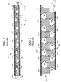
- FIG. 1 is a schematic view of a thermoelectric device in accordance with the prior art showing a Stonehenge configuration
- FIG 2 is a schematic view of a thermoelectric device in accordance with the prior art showing a stacked configuration
- FIG 3 is a schematic view of a single stage thermoelectric device in accordance with an exemplary embodiment.
- FIG. 4 is a schematic view of a two stage thermoelectric device in accordance with an exemplary embodiment.
- TE device 100 includes a hot side 104 and a cold side 105.
- Hot side 104 includes an electrically insulating header or insulator layer 110 having a first surface 111 and an opposing, second surface 112.
- a plurality of conductor leads or portions 120-124 are mounted to insulator layer 110.
- conductor portion 121 includes a body portion 130 including a base portion 132 that is mounted to first surface 111.
- Conductor portion 121 further includes a first angled side portion 134 and a second angled side portion 135.
- First and second angled side portions 134 and 135 extend from base portion 132 and are joined by a third side portion 136.
- First and second angled side portions 134 and 135 are arranged at an angle relative to a longitudinal axis defined by insulator layer 110, and relative to an axis that extends perpendicularly to the longitudinal axis, while third side portion 136 is substantially parallel to base portion 132 and first surface 111.
- conductor portion 122 includes a body portion 140 including a base portion 142 that is mounted to first surface 111.
- Conductor portion 122 further includes a first angled side portion 144 and a second angled side portion 145.
- First and second angled side portions 144 and 145 extend from base portion 140 and are joined by a third side portion 146.
- First and second angled side portions 144 and 145 are arranged at an angle relative to the longitudinal axis defined by insulator layer 110, and relative to an axis that extends perpendicularly to the longitudinal axis, while third side portion 146 is substantially parallel to base portion 140 and first surface 111.
- the remaining conductor portions 120 and 123-124 include similar structure. Also, as shown, each conductor portion 120-124 is spaced one from the other thereby forming a plurality of void regions 150-154.
- Cold side 105 includes an insulator layer 160 having a first surface 161 and an opposing, second surface 162.
- a plurality of conductor members 170-174 are mounted to insulator layer 160.
- conductor member 170 includes a body section 178 including a base section 180 that is mounted to first surface 161.
- Conductor member 170 further includes a first angled side section 181 and a second angled side section 182.
- First and second angled side sections 181 and 182 extend from base section 180 and are joined by a third side section 183.
- First and second angled side sections 181 and 182 are arranged at an angle relative to a longitudinal axis defined by insulator layer 160, and relative to an axis that extends perpendicularly to the longitudinal axis, while third side section 183 is substantially parallel to base portion 180 and first surface 161.
- conductor member 171 includes a body section 184 having a base section 185 that is mounted to first surface 161.
- Conductor member 171 further includes a first angled side section 187 and a second angled side section 188.
- First and second angled side sections 187 and 188 extend from base section 185 and are joined by a third side section 189.
- First and second angled side sections 187 and 188 are arranged at an angle relative to the longitudinal axis defined by insulator layer 160, and relative to an axis that extends perpendicularly to the longitudinal axis, while third side section 189 is substantially parallel to base section 185 and first surface 161.
- the remaining conductor members 172-174 include similar structure.
- each conductor member 170-174 is spaced one from the other thereby forming a plurality of void regions 191-195.
- hot side 104 is joined to cold side 105 through a plurality of N-type thermoelectric dies or members 200-204 and P-type thermoelectric dies or members 210-213. More specifically, cold side 105 is arranged relative to hot side 104 such that conductor portions 120-124 extend into respective ones of void regions 191-195 while remaining spaced from first surface 161 and conductor members 170-174 extend into respective ones of void regions 150-154 while remaining spaced from first surface 111.
- P-type thermoelectric member 210 joins first angled side portion 134 with first angled side section 181
- P-type thermoelectric member 211 joins first angled side portion 144 with first angled side section 187
- the remaining P-type thermoelectric members 212, 213 join the first angled side portions of conductor portions 123 and 124 with the first angled side sections of conductor members 172 and 173.
- N-type thermoelectric member 200 joins the second angled side portion (not separately labeled) of conductor portion 120 with second angled side section 182 of conductor member 170
- N-type thermoelectric member 201 joins second angled side portion 144 with second angled side section 187
- the remaining N-type thermoelectric members 202-204 join the second angled side portions of conductor portions 122-124 with the second angled side sections of conductor members 172-174.
- the plurality of N-type thermoelectric members 200-204 and plurality of P-type thermoelectric members 210-213 are angled relative to a longitudinal axis defined by insulator layers 110 and 160 and relative to an axis that extends perpendicularly to the longitudinal axis.
- an electrical current passing through conductor portions 120-124 and conductor members 170-174 flows in a curvilinear path defined by the respective angled side portions and angled side sections and a heat flux generated by the electrical current flows from hot side 104 to cold side 105 along a curvilinear path defined by the angles of the N-type members and P-type thermoelectric members.
- the shape of the curvilinear path of the electrical current and the curvilinear path of the heat flux can be adjusted by altering the magnitude of the angled side portions and angled side sections. By adjusting the curvilinear path of the electrical current and the curvilinear path of the heat flux, electrical and thermal efficiency of TE device 100 is enhanced.
- TE device 220 includes a hot side 224 and a cold side 225.
- Hot side 224 includes an insulator layer 228 having a first surface 229 and an opposing, second surface 230.
- a plurality of conductor portions 240-244 are mounted to insulator layer 228.
- conductor portion 240 includes a body portion 260 including a base portion 262 that is mounted to first surface 229.
- Conductor portion 240 further includes a first angled side portion 263 and a second angled side portion 264.
- First and second angled side portion 263 and 264 extend from base portion 262 and are joined by a third side portion 265.
- First and second angled side portions 263 and 264 are arranged at an angle relative to a longitudinal axis defined by insulator layer 228, and relative to an axis that extends perpendicularly to the longitudinal axis, while third side portion 265 is substantially parallel to base portion 262 and first surface 229.
- conductor portion 241 includes a body portion 270 including a base portion 272 that is mounted to first surface 229.
- Conductor portion 241 further includes a first angled side portion 273 and a second angled side portion 274.
- First and second angled side portions 273 and 274 extend from base portion 272 and are joined by a third side portion 275.
- First and second angled side portions 273 and 274 are arranged at an angle relative to the longitudinal axis defined by insulator layer 228 and relative to an axis that extends perpendicularly to the longitudinal axis, while third side portion 275 is substantially parallel to base portion 272 and first surface 229.
- the remaining conductor portions 242-244 include similar structure.
- each conductor portion 240-244 is spaced one from the other thereby forming a plurality of void regions 280-283.
- Cold side 225 includes an insulator layer 290 having a first surface 291 and an opposing, second surface 292.
- a plurality of conductor members 300-304 are mounted to insulator layer 290.
- conductor member 300 includes a body section 320 including a base section 322 that is mounted to first surface 291.
- Conductor member 300 further includes a first angled side section 323 and a second angled side section 324. First and second angled side sections 323 and 324 extend from base section 322 and are joined by a third side section 325.
- First and second angled side sections 323 and 324 are arranged at an angle relative to a longitudinal axis defined by insulator layer 290, and relative to an axis that extends perpendicularly to the longitudinal axis, while third side section 325 is substantially parallel to base portion 322 and first surface 291.
- conductor member 301 includes a body section 350 having a base section 352 that is mounted to first surface 291.
- Conductor member 301 further includes a first angled side section 353 and a second angled side section 354.
- First and second angled side sections 353 and 354 extend from base section 352 and are joined by a third side section 355.
- First and second angled side sections 353 and 354 are arranged at an angle relative to the longitudinal axis defined by insulator layer 290 and relative to an axis that extends perpendicularly to the longitudinal axis, while third side section 355 is substantially parallel to base section 352 and first surface 291.
- the remaining conductor members 302-304 include similar structure.
- each conductor member 300-304 is spaced one from the other thereby forming a plurality of void regions 380-383.
- cold side 225 is arranged relative to hot side 224 such that conductor members 300-303 face conductor portions 240-244 with regions 280-284 aligning with void regions 380-383 forming corresponding void zones 390-393.
- a plurality intermediate conductor members 400-403 are arranged in respective ones of void zones 390-393. As each intermediate conductor member 400-403 is similarly formed, a detailed description will follow referencing intermediate conductor member 400 with an understanding that the remaining intermediate conductor members 401-403 include corresponding structure.
- Intermediate conductor member 400 includes a body portion 404 having a plurality of angled side elements 405-410.
- a first plurality of P-type thermoelectric members 420-423, and a first plurality of N-type thermoelectric members 430-433 link conductor portions 240-244 to intermediate conductor members 400-403.
- P-type thermoelectric member 420 joins first angled side portion 273 with angled side element 407 of intermediate conductor member 400
- N-type thermoelectric member 430 joins second angled side portion 264 with angled side element 409 of intermediate conductor member 400.
- a first plurality of P-type thermoelectric members 450-453, and a first plurality of N-type thermoelectric members 460-463 link conductor members 300-304 to intermediate conductor members 400-403.
- P-type thermoelectric member 450 joins first angled side section 323 with angled side element 410 of intermediate conductor member 400
- N-type thermoelectric member 460 joins second angled side section 354 with angled side element 406 of intermediate conductor member 400.
- first and second pluralities of P-type members 420-423 and 450-453 and the first and second pluralities of N-type thermoelectric members 430-433, and 460-463 are angled relative to a longitudinal axis defined by insulator layers 228 and 290 and relative to an axis that extends perpendicularly to the longitudinal axis.
- an electrical current passing through conductor portions 240-244, intermediate conductor members 400-404 and conductor members 300-304 flows in a curvilinear path defined by the respective angled side portions, angled side elements, and angled side sections, and a heat flux generated by the electrical current flows from hot side 224 to cold side 225 along a curvilinear path defined by the angles of the N-type members and P-type members.
- the shape of the curvilinear path of the electrical current and curvilinear path of the heat flux can be adjusted by altering the magnitude of the angled side portions, angled side elements, and angled side sections.
- thermoelectric (TE) device having fewer stress concentrations than existing TE devices.
- the angled surfaces eliminate regions of high shear stress at an interface between TE members and conductor portions.
- the existing planar devices are subjected to interfacial shear created by transverse loading.
- Stacked devices are subjected to transverse shear by compressive loading.
- the angled architecture employed in connection with the exemplary embodiments distributes forces throughout the TE device thereby eliminating regions of pure shear at the interface regions. In addition to eliminating shear forces, the angled architecture reduces an overall weight of the TE device by eliminating material necessary in the planar and stacked configurations.
- the angled architecture enables the use of different size P-type thermoelectric and N-Type thermoelectric members. That is, as shown by altering the degree of each angled side portions of conductor portion 500 and conductor portion 505, or the angled side sections of the conductor members, P-type thermoelectric member 510 can be formed having a first size/shape and N-type thermoelectric member 515 can be formed having a second size/shape that is distinct from the first size/shape such as shown in FIG. 5 . In this manner, the flexibility, i.e., the ability to tailor the TE device to specific application is further enhanced.
Landscapes
- Cooling Or The Like Of Semiconductors Or Solid State Devices (AREA)
Abstract
Description
- The subject matter disclosed herein relates to thermoelectric devices and, more particularly, to an architectural configuration of a thermoelectric device.
- Thermoelectric devices include thermoelectric coolers that operate according to the Peltier effect in which an electrical input is transformed to a heat flux, and thermoelectric generators that operate according to the Seebeck effect in which a heat flux is transformed to an electrical output. Thermoelectric heat pumps or coolers are solid-state devices that use the Peltier effect to create a heat flux between junctions of two different types of materials. Heat is transferred from one side of the device to another side of the device against a thermal gradient with the consumption of electrical energy. Conversely, thermoelectric generators are solid-state devices that convert a heat flux between first and second sides into electrical energy. Both thermoelectric coolers and thermoelectric generators operate at about 5-10% efficiency.
- Conventional thermoelectric architecture includes a planar configuration, such as shown at 2 in
FIG. 1 and a stacked configuration such as shown at 4 inFIG. 2 .Planar configuration 2 includes ahot side 5 and acold side 6.Hot side 5 includes afirst insulator portion 7 having mounted thereto a plurality of conductors 8-12.Cold side 6 includes asecond insulator portion 14 having a plurality of conductors 20-24. Conductors 8-12 and 20-24 are joined though a plurality of N-type material members 30-34, and P-type material members 40-43. Upon the application of an electrical current, a heat flux is generated that flows fromhot side 5 to thecold side 6. With this arrangement, the heat flux passes along a substantially linear path from thehot side 5 to thecold side 6 while electrical flow through conductors 8-12 and 20-24 passes along a generally tortuous path. The generally tortuous path leads to losses that result in low operational efficiency. - Stacked configuration 4 includes a
hot side 50 and acold side 51.Hot side 50 includes afirst insulator portion 54 having extending therethrough a plurality of conductors 56-60.Cold side 51 includes asecond insulator portion 64 having extending therethrough a plurality of conductors 66-71.Cold side 51 is mounted tohot side 50 with conductors 56-60 being interleaved with conductors 66-71. In addition, conductors 56-60 and 66-71 are joined though a plurality of N-type material members 74-78, and P-type material members 80-84. Upon the application of an electrical current, a heat flux is generated that flows fromhot side 50 to thecold side 51. With this arrangement, the heat flux passes along a substantially tortuous path from thehot side 50 to thecold side 51 while the electrical flow through conductors 56-60 and 66-71 passes along a generally linear path. In a manner similar to that described above, the generally tortuous path leads to losses that result in low operational efficiency. - According to one aspect of the invention, a thermoelectric device includes a plurality of conductor portions including a base portion a first angled side portion, and a second angled side portion. The first angled side portion is coupled to the second angled side portion. The thermoelectric device also includes a plurality of conductor members including a base section, a first angled side section and a second angled side section. The first angled side section is coupled to the second angled side section. A plurality of P-type thermoelectric members interconnect corresponding ones of the first angled side portions with the first angled side sections. Each of the plurality of P-type thermoelectric members is angled relative to a longitudinal axis and an axis that extends perpendicular to the longitudinal axis. A plurality of N-type thermoelectric members interconnect corresponding ones of the second angled side portions with the second angled side sections. Each of the plurality of N-type thermoelectric members is angled relative to the longitudinal axis and the axis that extends perpendicular to the longitudinal axis. Electric flow through the plurality of conductor portions and conductor members passes along a first predefined curvilinear path and a heat flux passes along a second predefined curvilinear path.
- According to another aspect of the invention, a method of operating a thermoelectric device includes passing a heat flux from a first side of the thermoelectric device (100) to a second side of the thermoelectric device (100). The heat flux flows along a curvilinear path defined by at least one of a N-type thermoelectric member and a P-type thermoelectric member. The one of the N-type thermoelectric member and P-type thermoelectric member is at an angle relative to a longitudinal axis and an axis that extends perpendicular to the longitudinal axis. The method also includes guiding an electrical current through a plurality of conductor portions mounted relative to the first side and a plurality of conductor members mounted relative to the second side of the thermoelectric device. The electrical current flows along a curvilinear path defined by side portions of the plurality of conductor portions and side sections of the plurality of conductor members. The side portions and the side sections being at an angle relative to the longitudinal axis and the axis that extends perpendicular to the longitudinal axis.
- These and other advantages and features will become more apparent from the following description taken in conjunction with the drawings.
- The subject matter, which is regarded as the invention, is particularly pointed out and distinctly claimed in the claims at the conclusion of the specification. The foregoing and other features, and advantages of the invention are apparent from the following detailed description taken in conjunction with the accompanying drawings in which:
-
FIG. 1 is a schematic view of a thermoelectric device in accordance with the prior art showing a Stonehenge configuration; -
FIG 2 is a schematic view of a thermoelectric device in accordance with the prior art showing a stacked configuration; -
FIG 3 is a schematic view of a single stage thermoelectric device in accordance with an exemplary embodiment; and -
FIG. 4 is a schematic view of a two stage thermoelectric device in accordance with an exemplary embodiment. - The detailed description explains embodiments of the invention, together with advantages and features, by way of example with reference to the drawings.
- With reference to
FIG. 3 , a thermoelectric (TE) device constructed in accordance with an exemplary embodiment is indicated generally at 100.TE device 100 includes ahot side 104 and acold side 105.Hot side 104 includes an electrically insulating header orinsulator layer 110 having afirst surface 111 and an opposing,second surface 112. A plurality of conductor leads or portions 120-124 are mounted toinsulator layer 110. In the exemplary embodiment shown,conductor portion 121 includes abody portion 130 including abase portion 132 that is mounted tofirst surface 111.Conductor portion 121 further includes a firstangled side portion 134 and a secondangled side portion 135. First and secondangled side portions base portion 132 and are joined by athird side portion 136. First and secondangled side portions insulator layer 110, and relative to an axis that extends perpendicularly to the longitudinal axis, whilethird side portion 136 is substantially parallel tobase portion 132 andfirst surface 111. - Similarly,
conductor portion 122 includes abody portion 140 including abase portion 142 that is mounted tofirst surface 111.Conductor portion 122 further includes a firstangled side portion 144 and a secondangled side portion 145. First and secondangled side portions base portion 140 and are joined by athird side portion 146. First and secondangled side portions insulator layer 110, and relative to an axis that extends perpendicularly to the longitudinal axis, whilethird side portion 146 is substantially parallel tobase portion 140 andfirst surface 111. At this point it should be understood that theremaining conductor portions 120 and 123-124 include similar structure. Also, as shown, each conductor portion 120-124 is spaced one from the other thereby forming a plurality of void regions 150-154. -
Cold side 105 includes aninsulator layer 160 having afirst surface 161 and an opposing,second surface 162. A plurality of conductor members 170-174 are mounted toinsulator layer 160. In the exemplary embodiment shown,conductor member 170 includes abody section 178 including abase section 180 that is mounted tofirst surface 161.Conductor member 170 further includes a firstangled side section 181 and a secondangled side section 182. First and secondangled side sections base section 180 and are joined by athird side section 183. First and secondangled side sections insulator layer 160, and relative to an axis that extends perpendicularly to the longitudinal axis, whilethird side section 183 is substantially parallel tobase portion 180 andfirst surface 161. - Similarly,
conductor member 171 includes abody section 184 having abase section 185 that is mounted tofirst surface 161.Conductor member 171 further includes a firstangled side section 187 and a secondangled side section 188. First and secondangled side sections base section 185 and are joined by athird side section 189. First and secondangled side sections insulator layer 160, and relative to an axis that extends perpendicularly to the longitudinal axis, whilethird side section 189 is substantially parallel tobase section 185 andfirst surface 161. At this point it should be understood that the remaining conductor members 172-174 include similar structure. Also, as shown, each conductor member 170-174 is spaced one from the other thereby forming a plurality of void regions 191-195. - In accordance with the exemplary embodiment shown,
hot side 104 is joined tocold side 105 through a plurality of N-type thermoelectric dies or members 200-204 and P-type thermoelectric dies or members 210-213. More specifically,cold side 105 is arranged relative tohot side 104 such that conductor portions 120-124 extend into respective ones of void regions 191-195 while remaining spaced fromfirst surface 161 and conductor members 170-174 extend into respective ones of void regions 150-154 while remaining spaced fromfirst surface 111. In this manner, P-typethermoelectric member 210 joins first angledside portion 134 with firstangled side section 181, P-typethermoelectric member 211 joins first angledside portion 144 with firstangled side section 187, and the remaining P-typethermoelectric members conductor portions conductor members thermoelectric member 200 joins the second angled side portion (not separately labeled) ofconductor portion 120 with secondangled side section 182 ofconductor member 170, N-typethermoelectric member 201 joins secondangled side portion 144 with secondangled side section 187, and the remaining N-type thermoelectric members 202-204 join the second angled side portions of conductor portions 122-124 with the second angled side sections of conductor members 172-174. - In this manner, the plurality of N-type thermoelectric members 200-204 and plurality of P-type thermoelectric members 210-213 are angled relative to a longitudinal axis defined by
insulator layers hot side 104 tocold side 105 along a curvilinear path defined by the angles of the N-type members and P-type thermoelectric members. The shape of the curvilinear path of the electrical current and the curvilinear path of the heat flux can be adjusted by altering the magnitude of the angled side portions and angled side sections. By adjusting the curvilinear path of the electrical current and the curvilinear path of the heat flux, electrical and thermal efficiency ofTE device 100 is enhanced. - With reference to
FIG. 4 , a two-stage thermoelectric (TE) device, constructed in accordance with an exemplary embodiment, is indicated generally at 220.TE device 220 includes ahot side 224 and acold side 225.Hot side 224 includes aninsulator layer 228 having afirst surface 229 and an opposing,second surface 230. A plurality of conductor portions 240-244 are mounted toinsulator layer 228. In the exemplary embodiment shown,conductor portion 240 includes abody portion 260 including abase portion 262 that is mounted tofirst surface 229.Conductor portion 240 further includes a firstangled side portion 263 and a secondangled side portion 264. First and secondangled side portion base portion 262 and are joined by athird side portion 265. First and secondangled side portions insulator layer 228, and relative to an axis that extends perpendicularly to the longitudinal axis, whilethird side portion 265 is substantially parallel tobase portion 262 andfirst surface 229. - Similarly,
conductor portion 241 includes abody portion 270 including abase portion 272 that is mounted tofirst surface 229.Conductor portion 241 further includes a firstangled side portion 273 and a secondangled side portion 274. First and secondangled side portions base portion 272 and are joined by athird side portion 275. First and secondangled side portions insulator layer 228 and relative to an axis that extends perpendicularly to the longitudinal axis, whilethird side portion 275 is substantially parallel tobase portion 272 andfirst surface 229. At this point it should be understood that the remaining conductor portions 242-244 include similar structure. Also, as shown, each conductor portion 240-244 is spaced one from the other thereby forming a plurality of void regions 280-283. -
Cold side 225 includes aninsulator layer 290 having afirst surface 291 and an opposing,second surface 292. A plurality of conductor members 300-304 are mounted toinsulator layer 290. In the exemplary embodiment shown,conductor member 300 includes abody section 320 including abase section 322 that is mounted tofirst surface 291.Conductor member 300 further includes a first angled side section 323 and a secondangled side section 324. First and secondangled side sections 323 and 324 extend frombase section 322 and are joined by athird side section 325. First and secondangled side sections 323 and 324 are arranged at an angle relative to a longitudinal axis defined byinsulator layer 290, and relative to an axis that extends perpendicularly to the longitudinal axis, whilethird side section 325 is substantially parallel tobase portion 322 andfirst surface 291. - Similarly,
conductor member 301 includes abody section 350 having abase section 352 that is mounted tofirst surface 291.Conductor member 301 further includes a firstangled side section 353 and a secondangled side section 354. First and secondangled side sections base section 352 and are joined by a third side section 355. First and secondangled side sections insulator layer 290 and relative to an axis that extends perpendicularly to the longitudinal axis, while third side section 355 is substantially parallel tobase section 352 andfirst surface 291. At this point it should be understood that the remaining conductor members 302-304 include similar structure. Also, as shown, each conductor member 300-304 is spaced one from the other thereby forming a plurality of void regions 380-383. - In accordance with the exemplary embodiment shown,
cold side 225 is arranged relative tohot side 224 such that conductor members 300-303 face conductor portions 240-244 with regions 280-284 aligning with void regions 380-383 forming corresponding void zones 390-393. A plurality intermediate conductor members 400-403 are arranged in respective ones of void zones 390-393. As each intermediate conductor member 400-403 is similarly formed, a detailed description will follow referencingintermediate conductor member 400 with an understanding that the remaining intermediate conductor members 401-403 include corresponding structure. -
Intermediate conductor member 400 includes abody portion 404 having a plurality of angled side elements 405-410. A first plurality of P-type thermoelectric members 420-423, and a first plurality of N-type thermoelectric members 430-433 link conductor portions 240-244 to intermediate conductor members 400-403. For example, P-typethermoelectric member 420 joins first angledside portion 273 with angled side element 407 ofintermediate conductor member 400, and N-typethermoelectric member 430 joins secondangled side portion 264 withangled side element 409 ofintermediate conductor member 400. - Similarly, a first plurality of P-type thermoelectric members 450-453, and a first plurality of N-type thermoelectric members 460-463 link conductor members 300-304 to intermediate conductor members 400-403. For example, P-type thermoelectric member 450 joins first angled side section 323 with
angled side element 410 ofintermediate conductor member 400, and N-typethermoelectric member 460 joins secondangled side section 354 withangled side element 406 ofintermediate conductor member 400. In this manner, the first and second pluralities of P-type members 420-423 and 450-453 and the first and second pluralities of N-type thermoelectric members 430-433, and 460-463 are angled relative to a longitudinal axis defined byinsulator layers hot side 224 tocold side 225 along a curvilinear path defined by the angles of the N-type members and P-type members. The shape of the curvilinear path of the electrical current and curvilinear path of the heat flux can be adjusted by altering the magnitude of the angled side portions, angled side elements, and angled side sections. By adjusting the curvilinear paths of the electrical current and curvilinear path of the heat flux, electrical and thermal efficiency ofTE device 220 is enhanced. - At this point it should be understood that the exemplary embodiments form a thermoelectric (TE) device having fewer stress concentrations than existing TE devices. The angled surfaces eliminate regions of high shear stress at an interface between TE members and conductor portions. The existing planar devices are subjected to interfacial shear created by transverse loading. Stacked devices, on the other hand, are subjected to transverse shear by compressive loading. The angled architecture employed in connection with the exemplary embodiments distributes forces throughout the TE device thereby eliminating regions of pure shear at the interface regions. In addition to eliminating shear forces, the angled architecture reduces an overall weight of the TE device by eliminating material necessary in the planar and stacked configurations. Finally, the angled architecture enables the use of different size P-type thermoelectric and N-Type thermoelectric members. That is, as shown by altering the degree of each angled side portions of
conductor portion 500 andconductor portion 505, or the angled side sections of the conductor members, P-typethermoelectric member 510 can be formed having a first size/shape and N-typethermoelectric member 515 can be formed having a second size/shape that is distinct from the first size/shape such as shown inFIG. 5 . In this manner, the flexibility, i.e., the ability to tailor the TE device to specific application is further enhanced. - While the invention has been described in detail in connection with only a limited number of embodiments, it should be readily understood that the invention is not limited to such disclosed embodiments. Rather, the invention can be modified to incorporate any number of variations, alterations, substitutions or equivalent arrangements not heretofore described, but which are commensurate with the scope of the invention as defined by the claims. Additionally, while various embodiments of the invention have been described, it is to be understood that aspects of the invention may include only some of the described embodiments. Accordingly, the invention is not to be seen as limited by the foregoing description, but is only limited by the scope of the appended claims.
Claims (15)
- A thermoelectric device (100) comprising:a plurality of conductor portions (120-124) including a base portion (132), a first angled side portion (134), and a second angled side portion (135), the first angled side portion (134) being coupled to the second angled side portion (135);a plurality of conductor members (170-174) including a base section (180), a first angled side section (181), and a second angled side section (182), the first angled side section (181) being coupled to the second angled side section (182);a plurality of P-type thermoelectric members (210-213) interconnecting corresponding ones of the first angled side portions (134) with the first angled side sections (181), each of the plurality of P-type thermoelectric members (210-213) being angled relative to a longitudinal axis and an axis that extends perpendicular to the longitudinal axis; anda plurality of N-type thermoelectric members (200-204) interconnecting corresponding ones of the second angled side portions (135) with the second angled side sections (182), each of the plurality of N-type thermoelectric members (200-204) being angled relative to the longitudinal axis and the axis that extends perpendicular to the longitudinal axis, wherein electric flow through the plurality of conductor portions (120-124) and the plurality of conductor members (170-174) passes along a first predefined curvilinear path and a heat flux passes along a second predefined curvilinear path.
- The thermoelectric device (100) according to claim 1, further comprising: a first insulating layer (110) including a first surface (111) and a second surface (112), and a second insulating layer (160) including a first surface (161) and a second surface (162), wherein the plurality of conductor portions (120-124) are mounted to the first surface (111) of the first insulating layer (110) and the plurality of conductor members (170-174) are mounted to the first surface (161) of the second insulating layer (162).
- The thermoelectric device (100) according to claim 2, wherein each of the plurality of conductor portions (120-124) are spaced, one from the other, forming a first plurality of void regions (150-154), and each of the plurality of conductor members (170-174) are spaced, one from the other, forming a second plurality of void regions (191-195).
- The thermoelectric device (100) according to claim 3, wherein each of the plurality of conductor portions (120-124) extend into respective ones of the second plurality of void regions (191-195) and each of the plurality of conductor members (170-174) extend into respective ones of the first plurality of void regions (150-154).
- The thermoelectric device (100) according to claim 3, wherein each of the plurality of conductor portions (120-124) is spaced from the first surface (161) of the second insulating layer (160).
- The thermoelectric device (100) according to claim 3, wherein each of the plurality of conductor members (170-174) is spaced from the first surface (111) of the first insulating layer (110).
- The thermoelectric device (100) according to claim 3, wherein each of the plurality of conductor portions (120-124) is aligned with respective ones of each of the plurality of conducting members (170-174) with the first plurality of void regions (150-154) combining with the second plurality of void regions (191-195) to form a plurality of void zones (390-393).
- The thermoelectric device (220) according to claim 7, wherein each of the plurality of conducting portions (240-244) is spaced from respective ones of the plurality of conducting members (300-304).
- The thermoelectric device (220) according to claim 7, further comprising: a plurality of intermediate conductor members (400-403), each of the plurality of intermediate conductor members (400-403) being arranged in respective ones of the plurality of void zones (390-393).
- The thermoelectric device (220) according to claim 9, wherein each of the plurality of intermediate conductor members (400-403) includes a plurality of angled side elements (405-410).
- The thermoelectric device (220) according to claim 10, wherein the plurality of P-type members (430-433; 450-453) includes a first plurality of P-type thermoelectric members (430-433) that join respective ones of the first angled side portions (264) with an angled side element (409) of corresponding ones of the plurality of intermediate conductor members (400-403) and a second plurality of P-type thermoelectric members (450-453) that join another of the angled side elements (410) of corresponding ones of the plurality of intermediate conductor members (400-403) with respective ones of the first angled side section (323).
- The thermoelectric device (220) according to claim 10, wherein the plurality of N-type thermoelectric members (420-423;460-463) includes a first plurality of N-type thermoelectric members (420-423) that join respective ones of the second angled side portions (273) with an angled side element (407) of corresponding ones of the plurality of intermediate conductor members (400-403) and a second plurality of N-type thermoelectric members (460-463) that join another of the angled side elements (407) the of corresponding ones of the plurality of intermediate conductor members (400-403) with respective ones of the second angled side sections (354).
- The thermoelectric device (100, 220) according to claim 1, wherein the plurality of conductor portions (120-124) include a third side portion (136) joining the first and second angled side portions (134, 135), and the plurality of conductor members (170-174) include a third side section (183) joining the first and second angled side sections (181, 182).
- The thermoelectric device (100, 220) according to claim 1, wherein the first angled side portion (134) includes a first angle portion and the second angled side portion includes a second angle portion, the first angle portion being distinct from the second angle portion, and wherein the first angled side section (181) includes a first angle section and the side section (182) includes a second angle section, the first angle section being distinct from the second angle section; preferably wherein at least one of the plurality of P-type thermoelectric members (510) includes at least one of a first size and shape and at least one of the plurality of N-type thermoelectric members (515) includes at least one of a second size and shape, the at least one of the first size and shape being distinct from the at least one of the second size and shape.
- A method of operating a thermoelectric device (100), the method comprising:passing a heat flux from a first side (104) of the thermoelectric device (100) to a second side (105) of the thermoelectric device (100), the heat flux flowing along a curvilinear path defined by at least one of a N-type thermoelectric member (200-204) and a P-type thermoelectric member (210-213), the one of the N-type thermoelectric member (200-204) and P-type thermoelectric member (210-213) being at an angle relative to a longitudinal axis and an axis that extends perpendicular to the longitudinal axis; andguiding an electrical current through a plurality of conductor portions (120-124) mounted relative to the first side (104) and a plurality of conductor members (170-174) mounted relative to the second side (105) of the thermoelectric device (100), the electrical current flowing along a curvilinear path defined by side portions (134-136) of the plurality of conductor portions (120-124) and side sections (181-183) of the plurality of conductor members (170-174), the side portions (134-136) and side sections (181-183) being at an angle relative to the longitudinal axis and the axis that extends perpendicular to the longitudinal axis.
Applications Claiming Priority (1)
| Application Number | Priority Date | Filing Date | Title |
|---|---|---|---|
| US12/642,123 US8653358B2 (en) | 2009-12-18 | 2009-12-18 | Thermoelectric device architecture |
Publications (3)
| Publication Number | Publication Date |
|---|---|
| EP2337100A2 true EP2337100A2 (en) | 2011-06-22 |
| EP2337100A3 EP2337100A3 (en) | 2012-10-17 |
| EP2337100B1 EP2337100B1 (en) | 2017-05-03 |
Family
ID=43767624
Family Applications (1)
| Application Number | Title | Priority Date | Filing Date |
|---|---|---|---|
| EP10252150.7A Not-in-force EP2337100B1 (en) | 2009-12-18 | 2010-12-17 | Thermoelectric device architecture |
Country Status (2)
| Country | Link |
|---|---|
| US (1) | US8653358B2 (en) |
| EP (1) | EP2337100B1 (en) |
Cited By (2)
| Publication number | Priority date | Publication date | Assignee | Title |
|---|---|---|---|---|
| JP2014514904A (en) * | 2011-03-29 | 2014-06-19 | ユーリ・フェリコヴィッチ・ヴェルニコフスキー | Thermoelectric cluster, method for operating it, thermoelectric drive based thereon, generator (deformation) and device for connecting active elements in said cluster to heat pump (deformation) |
| EP2717463A3 (en) * | 2012-10-05 | 2017-04-26 | Hamilton Sundstrand Corporation | Electric motor braking using thermoelectric cooling |
Families Citing this family (7)
| Publication number | Priority date | Publication date | Assignee | Title |
|---|---|---|---|---|
| US9601677B2 (en) * | 2010-03-15 | 2017-03-21 | Laird Durham, Inc. | Thermoelectric (TE) devices/structures including thermoelectric elements with exposed major surfaces |
| KR101327732B1 (en) | 2011-12-15 | 2013-11-11 | 현대자동차주식회사 | Thermoelectric generator of vehicle |
| US8964388B2 (en) | 2012-09-30 | 2015-02-24 | Hamilton Sundstrand Corporation | Integrated blower diffuser and heat exchanger for electronics enclosure |
| CN104578913B (en) * | 2013-10-15 | 2017-03-29 | 天津大学 | The optimization structure of thermoelectric generator |
| US20240159445A1 (en) * | 2022-06-02 | 2024-05-16 | Faizan Ahmed | Thermo-electric system comprising chain trapezoid elements with increased figure of merit |
| DE102018130761B4 (en) * | 2018-12-04 | 2026-03-26 | Bayerische Motoren Werke Aktiengesellschaft | Thermoelectric conversion device and vehicle |
| US20250216126A1 (en) * | 2023-12-27 | 2025-07-03 | Faizan Ahmed | Thermoelectric system consisting of alternating trapezoid elements with increased figure of merit |
Family Cites Families (18)
| Publication number | Priority date | Publication date | Assignee | Title |
|---|---|---|---|---|
| US4465894A (en) | 1983-04-07 | 1984-08-14 | Ecd-Anr Energy Conversion Company | Substrateless thermoelectric device and method of making same |
| US5367890A (en) * | 1993-07-13 | 1994-11-29 | Marlow Industries, Inc. | Integrated thermoelectric system with full/half wave rectifier control |
| US5610366A (en) | 1993-08-03 | 1997-03-11 | California Institute Of Technology | High performance thermoelectric materials and methods of preparation |
| WO1998044562A1 (en) | 1997-03-31 | 1998-10-08 | Research Triangle Institute | Thin-film thermoelectric device and fabrication method of same |
| US20060021648A1 (en) | 1997-05-09 | 2006-02-02 | Parise Ronald J | Device and method to transmit waste heat or thermal pollution into deep space |
| US5936193A (en) * | 1997-05-09 | 1999-08-10 | Parise; Ronald J. | Nighttime solar cell |
| JP2001320097A (en) | 2000-05-09 | 2001-11-16 | Komatsu Ltd | Thermoelectric element, method of manufacturing the same, and thermoelectric module using the same |
| US6411109B1 (en) | 2000-05-19 | 2002-06-25 | Hamilton Sundstrand Corporation | Connecting lug used as a current-sense resistor |
| US6739138B2 (en) | 2001-11-26 | 2004-05-25 | Innovations Inc. | Thermoelectric modules and a heating and cooling apparatus incorporating same |
| KR20030064292A (en) * | 2002-01-25 | 2003-07-31 | 가부시키가이샤 고마쓰 세이사쿠쇼 | Thermoelectric module |
| US6705089B2 (en) | 2002-04-04 | 2004-03-16 | International Business Machines Corporation | Two stage cooling system employing thermoelectric modules |
| US8455751B2 (en) * | 2003-12-02 | 2013-06-04 | Battelle Memorial Institute | Thermoelectric devices and applications for the same |
| WO2006033875A2 (en) | 2004-09-09 | 2006-03-30 | Orobridge, Inc. | Thermoelectric devices with controlled current flow and related methods |
| US7544883B2 (en) | 2004-11-12 | 2009-06-09 | International Business Machines Corporation | Integrated thermoelectric cooling devices and methods for fabricating same |
| US8044293B2 (en) | 2005-02-18 | 2011-10-25 | GM Global Technology Operations LLC | High performance thermoelectric nanocomposite device |
| US8313056B2 (en) | 2005-07-19 | 2012-11-20 | United Technologies Corporation | Engine heat exchanger with thermoelectric generation |
| US8378205B2 (en) | 2006-09-29 | 2013-02-19 | United Technologies Corporation | Thermoelectric heat exchanger |
| AT508277B1 (en) | 2009-06-09 | 2011-09-15 | Avl List Gmbh | THERMOELECTRIC MODULE WITH PAIR-TYPED P AND N-DOTED TILES |
-
2009
- 2009-12-18 US US12/642,123 patent/US8653358B2/en not_active Expired - Fee Related
-
2010
- 2010-12-17 EP EP10252150.7A patent/EP2337100B1/en not_active Not-in-force
Non-Patent Citations (1)
| Title |
|---|
| None |
Cited By (2)
| Publication number | Priority date | Publication date | Assignee | Title |
|---|---|---|---|---|
| JP2014514904A (en) * | 2011-03-29 | 2014-06-19 | ユーリ・フェリコヴィッチ・ヴェルニコフスキー | Thermoelectric cluster, method for operating it, thermoelectric drive based thereon, generator (deformation) and device for connecting active elements in said cluster to heat pump (deformation) |
| EP2717463A3 (en) * | 2012-10-05 | 2017-04-26 | Hamilton Sundstrand Corporation | Electric motor braking using thermoelectric cooling |
Also Published As
| Publication number | Publication date |
|---|---|
| US20110146740A1 (en) | 2011-06-23 |
| EP2337100B1 (en) | 2017-05-03 |
| EP2337100A3 (en) | 2012-10-17 |
| US8653358B2 (en) | 2014-02-18 |
Similar Documents
| Publication | Publication Date | Title |
|---|---|---|
| EP2337100B1 (en) | Thermoelectric device architecture | |
| Kim et al. | The bridge between the materials and devices of thermoelectric power generators | |
| CN101529606B (en) | Thermoelectric element and thermoelectric module | |
| Crane et al. | Progress towards maximizing the performance of a thermoelectric power generator | |
| EP2070129B1 (en) | Thermoelectric power generating systems utilizing segmented thermoelectric elements | |
| US20100031987A1 (en) | Enhanced thermally isolated thermoelectrics | |
| EP1906463A3 (en) | Thermoelectric heat exchanger | |
| Jin | Thermal stresses in a multilayered thin film thermoelectric structure | |
| KR20170096148A (en) | Thermoelectric power generation module | |
| Xu et al. | High performance of Bi2Te3-based thermoelectric generator owing to pressure in fabrication process | |
| CZ2011671A3 (en) | Thermoelectric cluster, method of its operation, mechanism for connecting an active element with a thermal electric conductor, generator and heat pump made on the base thereof | |
| Erturun et al. | Thermoelectric devices with rotated and coaxial leg configurations: Numerical analysis of performance | |
| KR20150134335A (en) | Thermoelectric conversion element | |
| US20180240956A1 (en) | Flexible thermoelectric generator | |
| Hendricks et al. | New perspectives in thermoelectric energy recovery system design optimization | |
| US20170077379A1 (en) | Applying compliant compliant interfacial layers in thermoelectric devices | |
| JP2008010764A (en) | Thermoelectric converter | |
| CN102714268B (en) | There is the electrothermal module of the post of p and the n doping arranged in pairs | |
| Basu | Thermoelectric modules: key issues in architectural design and contact optimization | |
| Haras et al. | Unconventional thin-film thermoelectric converters: structure, simulation, and comparative study | |
| JP2013048234A (en) | Thermoelectric module and method for producing thermoelectric module | |
| Kim et al. | Design of linear shaped thermoelectric generator and self-integration using shape memory alloy | |
| US20130125948A1 (en) | Thermoelectric conversion element, manufacturing method for the thermoelectric conversion element, and thermoelectric conversion module | |
| US20120060886A1 (en) | High temperature flexible electrode | |
| Bass et al. | New technology for thermoelectric cooling |
Legal Events
| Date | Code | Title | Description |
|---|---|---|---|
| PUAI | Public reference made under article 153(3) epc to a published international application that has entered the european phase |
Free format text: ORIGINAL CODE: 0009012 |
|
| AK | Designated contracting states |
Kind code of ref document: A2 Designated state(s): AL AT BE BG CH CY CZ DE DK EE ES FI FR GB GR HR HU IE IS IT LI LT LU LV MC MK MT NL NO PL PT RO RS SE SI SK SM TR |
|
| AX | Request for extension of the european patent |
Extension state: BA ME |
|
| PUAL | Search report despatched |
Free format text: ORIGINAL CODE: 0009013 |
|
| AK | Designated contracting states |
Kind code of ref document: A3 Designated state(s): AL AT BE BG CH CY CZ DE DK EE ES FI FR GB GR HR HU IE IS IT LI LT LU LV MC MK MT NL NO PL PT RO RS SE SI SK SM TR |
|
| AX | Request for extension of the european patent |
Extension state: BA ME |
|
| RIC1 | Information provided on ipc code assigned before grant |
Ipc: H01L 35/32 20060101AFI20120912BHEP |
|
| 17P | Request for examination filed |
Effective date: 20130415 |
|
| 17Q | First examination report despatched |
Effective date: 20140523 |
|
| GRAP | Despatch of communication of intention to grant a patent |
Free format text: ORIGINAL CODE: EPIDOSNIGR1 |
|
| INTG | Intention to grant announced |
Effective date: 20161123 |
|
| GRAS | Grant fee paid |
Free format text: ORIGINAL CODE: EPIDOSNIGR3 |
|
| GRAA | (expected) grant |
Free format text: ORIGINAL CODE: 0009210 |
|
| AK | Designated contracting states |
Kind code of ref document: B1 Designated state(s): AL AT BE BG CH CY CZ DE DK EE ES FI FR GB GR HR HU IE IS IT LI LT LU LV MC MK MT NL NO PL PT RO RS SE SI SK SM TR |
|
| REG | Reference to a national code |
Ref country code: GB Ref legal event code: FG4D |
|
| REG | Reference to a national code |
Ref country code: AT Ref legal event code: REF Ref document number: 890874 Country of ref document: AT Kind code of ref document: T Effective date: 20170515 Ref country code: CH Ref legal event code: EP |
|
| REG | Reference to a national code |
Ref country code: IE Ref legal event code: FG4D |
|
| REG | Reference to a national code |
Ref country code: DE Ref legal event code: R096 Ref document number: 602010041989 Country of ref document: DE |
|
| REG | Reference to a national code |
Ref country code: NL Ref legal event code: MP Effective date: 20170503 |
|
| REG | Reference to a national code |
Ref country code: AT Ref legal event code: MK05 Ref document number: 890874 Country of ref document: AT Kind code of ref document: T Effective date: 20170503 |
|
| REG | Reference to a national code |
Ref country code: LT Ref legal event code: MG4D |
|
| PG25 | Lapsed in a contracting state [announced via postgrant information from national office to epo] |
Ref country code: LT Free format text: LAPSE BECAUSE OF FAILURE TO SUBMIT A TRANSLATION OF THE DESCRIPTION OR TO PAY THE FEE WITHIN THE PRESCRIBED TIME-LIMIT Effective date: 20170503 Ref country code: NO Free format text: LAPSE BECAUSE OF FAILURE TO SUBMIT A TRANSLATION OF THE DESCRIPTION OR TO PAY THE FEE WITHIN THE PRESCRIBED TIME-LIMIT Effective date: 20170803 Ref country code: HR Free format text: LAPSE BECAUSE OF FAILURE TO SUBMIT A TRANSLATION OF THE DESCRIPTION OR TO PAY THE FEE WITHIN THE PRESCRIBED TIME-LIMIT Effective date: 20170503 Ref country code: FI Free format text: LAPSE BECAUSE OF FAILURE TO SUBMIT A TRANSLATION OF THE DESCRIPTION OR TO PAY THE FEE WITHIN THE PRESCRIBED TIME-LIMIT Effective date: 20170503 Ref country code: GR Free format text: LAPSE BECAUSE OF FAILURE TO SUBMIT A TRANSLATION OF THE DESCRIPTION OR TO PAY THE FEE WITHIN THE PRESCRIBED TIME-LIMIT Effective date: 20170804 Ref country code: ES Free format text: LAPSE BECAUSE OF FAILURE TO SUBMIT A TRANSLATION OF THE DESCRIPTION OR TO PAY THE FEE WITHIN THE PRESCRIBED TIME-LIMIT Effective date: 20170503 Ref country code: AT Free format text: LAPSE BECAUSE OF FAILURE TO SUBMIT A TRANSLATION OF THE DESCRIPTION OR TO PAY THE FEE WITHIN THE PRESCRIBED TIME-LIMIT Effective date: 20170503 |
|
| REG | Reference to a national code |
Ref country code: FR Ref legal event code: PLFP Year of fee payment: 8 |
|
| PG25 | Lapsed in a contracting state [announced via postgrant information from national office to epo] |
Ref country code: NL Free format text: LAPSE BECAUSE OF FAILURE TO SUBMIT A TRANSLATION OF THE DESCRIPTION OR TO PAY THE FEE WITHIN THE PRESCRIBED TIME-LIMIT Effective date: 20170503 Ref country code: IS Free format text: LAPSE BECAUSE OF FAILURE TO SUBMIT A TRANSLATION OF THE DESCRIPTION OR TO PAY THE FEE WITHIN THE PRESCRIBED TIME-LIMIT Effective date: 20170903 Ref country code: RS Free format text: LAPSE BECAUSE OF FAILURE TO SUBMIT A TRANSLATION OF THE DESCRIPTION OR TO PAY THE FEE WITHIN THE PRESCRIBED TIME-LIMIT Effective date: 20170503 Ref country code: BG Free format text: LAPSE BECAUSE OF FAILURE TO SUBMIT A TRANSLATION OF THE DESCRIPTION OR TO PAY THE FEE WITHIN THE PRESCRIBED TIME-LIMIT Effective date: 20170803 Ref country code: PL Free format text: LAPSE BECAUSE OF FAILURE TO SUBMIT A TRANSLATION OF THE DESCRIPTION OR TO PAY THE FEE WITHIN THE PRESCRIBED TIME-LIMIT Effective date: 20170503 Ref country code: LV Free format text: LAPSE BECAUSE OF FAILURE TO SUBMIT A TRANSLATION OF THE DESCRIPTION OR TO PAY THE FEE WITHIN THE PRESCRIBED TIME-LIMIT Effective date: 20170503 Ref country code: SE Free format text: LAPSE BECAUSE OF FAILURE TO SUBMIT A TRANSLATION OF THE DESCRIPTION OR TO PAY THE FEE WITHIN THE PRESCRIBED TIME-LIMIT Effective date: 20170503 |
|
| PG25 | Lapsed in a contracting state [announced via postgrant information from national office to epo] |
Ref country code: CZ Free format text: LAPSE BECAUSE OF FAILURE TO SUBMIT A TRANSLATION OF THE DESCRIPTION OR TO PAY THE FEE WITHIN THE PRESCRIBED TIME-LIMIT Effective date: 20170503 Ref country code: SK Free format text: LAPSE BECAUSE OF FAILURE TO SUBMIT A TRANSLATION OF THE DESCRIPTION OR TO PAY THE FEE WITHIN THE PRESCRIBED TIME-LIMIT Effective date: 20170503 Ref country code: EE Free format text: LAPSE BECAUSE OF FAILURE TO SUBMIT A TRANSLATION OF THE DESCRIPTION OR TO PAY THE FEE WITHIN THE PRESCRIBED TIME-LIMIT Effective date: 20170503 Ref country code: DK Free format text: LAPSE BECAUSE OF FAILURE TO SUBMIT A TRANSLATION OF THE DESCRIPTION OR TO PAY THE FEE WITHIN THE PRESCRIBED TIME-LIMIT Effective date: 20170503 Ref country code: RO Free format text: LAPSE BECAUSE OF FAILURE TO SUBMIT A TRANSLATION OF THE DESCRIPTION OR TO PAY THE FEE WITHIN THE PRESCRIBED TIME-LIMIT Effective date: 20170503 |
|
| REG | Reference to a national code |
Ref country code: DE Ref legal event code: R097 Ref document number: 602010041989 Country of ref document: DE |
|
| PG25 | Lapsed in a contracting state [announced via postgrant information from national office to epo] |
Ref country code: SM Free format text: LAPSE BECAUSE OF FAILURE TO SUBMIT A TRANSLATION OF THE DESCRIPTION OR TO PAY THE FEE WITHIN THE PRESCRIBED TIME-LIMIT Effective date: 20170503 Ref country code: IT Free format text: LAPSE BECAUSE OF FAILURE TO SUBMIT A TRANSLATION OF THE DESCRIPTION OR TO PAY THE FEE WITHIN THE PRESCRIBED TIME-LIMIT Effective date: 20170503 |
|
| PLBE | No opposition filed within time limit |
Free format text: ORIGINAL CODE: 0009261 |
|
| STAA | Information on the status of an ep patent application or granted ep patent |
Free format text: STATUS: NO OPPOSITION FILED WITHIN TIME LIMIT |
|
| 26N | No opposition filed |
Effective date: 20180206 |
|
| PG25 | Lapsed in a contracting state [announced via postgrant information from national office to epo] |
Ref country code: SI Free format text: LAPSE BECAUSE OF FAILURE TO SUBMIT A TRANSLATION OF THE DESCRIPTION OR TO PAY THE FEE WITHIN THE PRESCRIBED TIME-LIMIT Effective date: 20170503 |
|
| REG | Reference to a national code |
Ref country code: DE Ref legal event code: R119 Ref document number: 602010041989 Country of ref document: DE |
|
| REG | Reference to a national code |
Ref country code: CH Ref legal event code: PL |
|
| REG | Reference to a national code |
Ref country code: IE Ref legal event code: MM4A |
|
| PG25 | Lapsed in a contracting state [announced via postgrant information from national office to epo] |
Ref country code: LU Free format text: LAPSE BECAUSE OF NON-PAYMENT OF DUE FEES Effective date: 20171217 Ref country code: MT Free format text: LAPSE BECAUSE OF NON-PAYMENT OF DUE FEES Effective date: 20171217 |
|
| REG | Reference to a national code |
Ref country code: BE Ref legal event code: MM Effective date: 20171231 |
|
| PG25 | Lapsed in a contracting state [announced via postgrant information from national office to epo] |
Ref country code: IE Free format text: LAPSE BECAUSE OF NON-PAYMENT OF DUE FEES Effective date: 20171217 Ref country code: DE Free format text: LAPSE BECAUSE OF NON-PAYMENT OF DUE FEES Effective date: 20180703 |
|
| PG25 | Lapsed in a contracting state [announced via postgrant information from national office to epo] |
Ref country code: LI Free format text: LAPSE BECAUSE OF NON-PAYMENT OF DUE FEES Effective date: 20171231 Ref country code: CH Free format text: LAPSE BECAUSE OF NON-PAYMENT OF DUE FEES Effective date: 20171231 Ref country code: BE Free format text: LAPSE BECAUSE OF NON-PAYMENT OF DUE FEES Effective date: 20171231 |
|
| PG25 | Lapsed in a contracting state [announced via postgrant information from national office to epo] |
Ref country code: HU Free format text: LAPSE BECAUSE OF FAILURE TO SUBMIT A TRANSLATION OF THE DESCRIPTION OR TO PAY THE FEE WITHIN THE PRESCRIBED TIME-LIMIT; INVALID AB INITIO Effective date: 20101217 Ref country code: MC Free format text: LAPSE BECAUSE OF FAILURE TO SUBMIT A TRANSLATION OF THE DESCRIPTION OR TO PAY THE FEE WITHIN THE PRESCRIBED TIME-LIMIT Effective date: 20170503 |
|
| PG25 | Lapsed in a contracting state [announced via postgrant information from national office to epo] |
Ref country code: CY Free format text: LAPSE BECAUSE OF NON-PAYMENT OF DUE FEES Effective date: 20170503 |
|
| PG25 | Lapsed in a contracting state [announced via postgrant information from national office to epo] |
Ref country code: MK Free format text: LAPSE BECAUSE OF FAILURE TO SUBMIT A TRANSLATION OF THE DESCRIPTION OR TO PAY THE FEE WITHIN THE PRESCRIBED TIME-LIMIT Effective date: 20170503 |
|
| PG25 | Lapsed in a contracting state [announced via postgrant information from national office to epo] |
Ref country code: TR Free format text: LAPSE BECAUSE OF FAILURE TO SUBMIT A TRANSLATION OF THE DESCRIPTION OR TO PAY THE FEE WITHIN THE PRESCRIBED TIME-LIMIT Effective date: 20170503 |
|
| PG25 | Lapsed in a contracting state [announced via postgrant information from national office to epo] |
Ref country code: PT Free format text: LAPSE BECAUSE OF FAILURE TO SUBMIT A TRANSLATION OF THE DESCRIPTION OR TO PAY THE FEE WITHIN THE PRESCRIBED TIME-LIMIT Effective date: 20170503 |
|
| PG25 | Lapsed in a contracting state [announced via postgrant information from national office to epo] |
Ref country code: AL Free format text: LAPSE BECAUSE OF FAILURE TO SUBMIT A TRANSLATION OF THE DESCRIPTION OR TO PAY THE FEE WITHIN THE PRESCRIBED TIME-LIMIT Effective date: 20170503 |
|
| PGFP | Annual fee paid to national office [announced via postgrant information from national office to epo] |
Ref country code: GB Payment date: 20201123 Year of fee payment: 11 Ref country code: FR Payment date: 20201120 Year of fee payment: 11 |
|
| GBPC | Gb: european patent ceased through non-payment of renewal fee |
Effective date: 20211217 |
|
| PG25 | Lapsed in a contracting state [announced via postgrant information from national office to epo] |
Ref country code: GB Free format text: LAPSE BECAUSE OF NON-PAYMENT OF DUE FEES Effective date: 20211217 |
|
| PG25 | Lapsed in a contracting state [announced via postgrant information from national office to epo] |
Ref country code: FR Free format text: LAPSE BECAUSE OF NON-PAYMENT OF DUE FEES Effective date: 20211231 |