EP2337055A1 - Illuminating lamp and method of making same - Google Patents
Illuminating lamp and method of making same Download PDFInfo
- Publication number
- EP2337055A1 EP2337055A1 EP10194270A EP10194270A EP2337055A1 EP 2337055 A1 EP2337055 A1 EP 2337055A1 EP 10194270 A EP10194270 A EP 10194270A EP 10194270 A EP10194270 A EP 10194270A EP 2337055 A1 EP2337055 A1 EP 2337055A1
- Authority
- EP
- European Patent Office
- Prior art keywords
- burner
- stem
- mounting portion
- slot
- pair
- Prior art date
- Legal status (The legal status is an assumption and is not a legal conclusion. Google has not performed a legal analysis and makes no representation as to the accuracy of the status listed.)
- Granted
Links
- 238000004519 manufacturing process Methods 0.000 title abstract description 13
- 239000000919 ceramic Substances 0.000 claims abstract description 37
- 229910052736 halogen Inorganic materials 0.000 claims abstract description 27
- 150000002367 halogens Chemical class 0.000 claims abstract description 27
- 239000010453 quartz Substances 0.000 claims abstract description 26
- VYPSYNLAJGMNEJ-UHFFFAOYSA-N silicon dioxide Inorganic materials O=[Si]=O VYPSYNLAJGMNEJ-UHFFFAOYSA-N 0.000 claims abstract description 26
- 238000000034 method Methods 0.000 claims abstract description 25
- 239000000463 material Substances 0.000 claims abstract description 15
- 239000012780 transparent material Substances 0.000 claims abstract description 4
- 238000003466 welding Methods 0.000 claims 1
- 239000000853 adhesive Substances 0.000 abstract description 8
- 230000001070 adhesive effect Effects 0.000 abstract description 8
- IJGRMHOSHXDMSA-UHFFFAOYSA-N Atomic nitrogen Chemical compound N#N IJGRMHOSHXDMSA-UHFFFAOYSA-N 0.000 description 4
- QSHDDOUJBYECFT-UHFFFAOYSA-N mercury Chemical compound [Hg] QSHDDOUJBYECFT-UHFFFAOYSA-N 0.000 description 4
- 229910052753 mercury Inorganic materials 0.000 description 4
- 230000004075 alteration Effects 0.000 description 2
- 229910052751 metal Inorganic materials 0.000 description 2
- 239000002184 metal Substances 0.000 description 2
- 238000012986 modification Methods 0.000 description 2
- 230000004048 modification Effects 0.000 description 2
- 229910052757 nitrogen Inorganic materials 0.000 description 2
- XUIMIQQOPSSXEZ-UHFFFAOYSA-N Silicon Chemical compound [Si] XUIMIQQOPSSXEZ-UHFFFAOYSA-N 0.000 description 1
- 230000000712 assembly Effects 0.000 description 1
- 238000000429 assembly Methods 0.000 description 1
- 230000000694 effects Effects 0.000 description 1
- 238000010891 electric arc Methods 0.000 description 1
- -1 for example Substances 0.000 description 1
- 239000003292 glue Substances 0.000 description 1
- 150000004820 halides Chemical class 0.000 description 1
- 230000000977 initiatory effect Effects 0.000 description 1
- 229910001507 metal halide Inorganic materials 0.000 description 1
- 150000005309 metal halides Chemical class 0.000 description 1
- 239000012811 non-conductive material Substances 0.000 description 1
- 229910052710 silicon Inorganic materials 0.000 description 1
- 239000010703 silicon Substances 0.000 description 1
- 239000007787 solid Substances 0.000 description 1
Images




Classifications
-
- H—ELECTRICITY
- H01—ELECTRIC ELEMENTS
- H01J—ELECTRIC DISCHARGE TUBES OR DISCHARGE LAMPS
- H01J5/00—Details relating to vessels or to leading-in conductors common to two or more basic types of discharge tubes or lamps
- H01J5/48—Means forming part of the tube or lamp for the purpose of supporting it
-
- H—ELECTRICITY
- H01—ELECTRIC ELEMENTS
- H01J—ELECTRIC DISCHARGE TUBES OR DISCHARGE LAMPS
- H01J61/00—Gas-discharge or vapour-discharge lamps
- H01J61/02—Details
- H01J61/30—Vessels; Containers
- H01J61/34—Double-wall vessels or containers
-
- H—ELECTRICITY
- H01—ELECTRIC ELEMENTS
- H01K—ELECTRIC INCANDESCENT LAMPS
- H01K1/00—Details
- H01K1/28—Envelopes; Vessels
- H01K1/34—Double wall vessels
-
- H—ELECTRICITY
- H01—ELECTRIC ELEMENTS
- H01K—ELECTRIC INCANDESCENT LAMPS
- H01K1/00—Details
- H01K1/42—Means forming part of the lamp for the purpose of providing electrical connection, or support for, the lamp
- H01K1/46—Means forming part of the lamp for the purpose of providing electrical connection, or support for, the lamp supported by a separate part, e.g. base, cap
-
- Y—GENERAL TAGGING OF NEW TECHNOLOGICAL DEVELOPMENTS; GENERAL TAGGING OF CROSS-SECTIONAL TECHNOLOGIES SPANNING OVER SEVERAL SECTIONS OF THE IPC; TECHNICAL SUBJECTS COVERED BY FORMER USPC CROSS-REFERENCE ART COLLECTIONS [XRACs] AND DIGESTS
- Y02—TECHNOLOGIES OR APPLICATIONS FOR MITIGATION OR ADAPTATION AGAINST CLIMATE CHANGE
- Y02B—CLIMATE CHANGE MITIGATION TECHNOLOGIES RELATED TO BUILDINGS, e.g. HOUSING, HOUSE APPLIANCES OR RELATED END-USER APPLICATIONS
- Y02B20/00—Energy efficient lighting technologies, e.g. halogen lamps or gas discharge lamps
Definitions
- incandescent lamps In an effort to reduce electrical power consumption, it has become desirable to replace incandescent lamps with more efficient lamps such as high efficiency line voltage quarts halogen burner lamps and high intensity arc discharge (HID) burner lamps.
- lamps have heretofore required special mountings, particularly for double-ended burners, i.e., burners with electrodes extending from opposite ends thereof.
- Single ended quartz halogen and HID burners also require special mounting and provision for attachment to the burner electrodes.
- quartz halogen and HID lamps have been desired to provide for high volume manufacture quartz halogen and HID lamps and to provide for mounting same on an incandescent lamp base for providing a lamp which may be threaded into an existing socket on an incandescent lamp fixture and to provide a design for such lamps which enables manufacturing with existing equipment utilized for incandescent lamps.
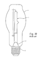
- FIGURE 10 shows an existing quartz halogen lamp burner indicated generally at 1 attached to a stem indicated generally at 2 inserted in a threaded incandescent lamp base 3 with an outer transparent covered bulb 4.
- FIGURE 11 shows an existing mercury HID lamp burner 5 with initiating electrode 6 fed through a dropping resistor 7, connected to stem 8 and threaded base 9 with outer bulb B which may be translucent or transparent.
- Bulb B is typically filled with nitrogen.
- FIGURE 12 is a view of an existing metal halide plus mercury lamp burner 5' with electrodes 6', 6" fed through dropping resistor 7' and mounted on stem 8' of threaded base 9' and covered with a bulb B'.
- the bulb B' is typically filled with nitrogen.
- the present disclosure describes a quartz halogen or HID lamp of either a single end configuration wherein the electrodes extend outwardly of one end or a double end burner configuration in which electrodes extends from each opposite end of the burner and the technique of attaching or mounting either type of burner to the stem of an existing threaded base of the type employed in an incandescent lamp.
- the arrangement of the present disclosure permits the quartz halogen or HID burner to be attached or mounted on a ceramic member and secured to the ceramic member by cementing thereto and disposing the ceramic member over the stem extending from the incandescent lamp base for attachment thereto.
- the stem is attached to the threaded base by conventional means.
- An outer bulb may then be received over the assembly of the quartz halogen or HID burner and base and secured to the incandescent lamp base in a manner which may give the appearance of an incandescent light bulb.
- a sub-assembly of an embodiment of a quartz halogen burner is indicated generally at 10 and includes a single ended quartz halogen burner 12 oriented vertically having a pair of electrodes 14, 16 extending from opposites sides thereof in a generally horizontal direction.
- the lower portion of the burner 12 is formed in a pinched or flattened blade-type configuration as denoted by reference numeral 18 to facilitate mounting of the burner 12.
- a ceramic member 20 having a generally tubular configuration has a slot 22 formed therein into which is received the blade portion 18 of the burner 12.
- the ceramic member 20 may have a generally cylindrical configuration or other cross-section such as elliptical or polygonal.
- elastic heat resistant adhesive such as, for example, silicon based heat resistant glue such as Loctite® 5088 or other similar material.
- a cementitious material is employed for bonding the blade to the ceramic member, it has been found satisfactory to employ Sauefeld 31 material available from Sauereisen, 160 Gamma Drive, Pittsburgh, PA 15238-2989.
- the tubular ceramic member 20 is shown as having the slot 22 formed therein with a narrower sub-slot 24 formed in the lower closed end of slot 22 for permitting the electrodes 14, 16 to pass therethrough when the blade 18 is received in the slot 22.
- the assemblage of the burner 12 and ceramic member 20 is then secured over the upper portion of a stem 26, which is of the type adapted for being received in the base of a conventional incandescent lamp such as, for example, that denoted by reference numeral 62 in FIGURE 8 .
- the ceramic member 20 may then be bonded or attached to the upper portion of stem 26 in the same manner as blade 18 was secured to the member 20; and, the same type of cementitious material or elastic heat resistant adhesive may be employed.
- tubular ceramic member 20 preferably has a tubular configuration, but alternatively may be a solid member with recesses formed in opposite sides or ends for receiving and attaching the burner pinch and base stem.
- the electrodes 14, 16 have lead wires 28, 30 extending from the stem 26 attached respectively thereto by any convenient expedient as, for example, weldment. It will be understood that the leads 28, 30 extend downwardly through the stem and are attached to the base of the lamp in a manner well known in the art.
- FIGURES 5 and 6 another version of the lamp of the present disclosure is indicated generally at 40 and which comprises a sub-assembly of a double ended quartz halogen burner 42 with an electrode 44 extending from the upper end thereof and with an electrode 36 extending from the opposite or lower end thereof.
- the burner 42 has a pinched or flattened blade like mounting portion on one end thereof opposite electrode 44, which blade portion is denoted by reference numeral 48 in FIGURES 5 and 6 .
- the blade portion 48 of the double ended burner 42 is received in a slot 50 provided in a generally tubular ceramic member 52 and secured therein with cementitious material or elastic heat resistant adhesive in the manner similar to the version shown in FIGURES 1-4 .
- the ceramic member 52 is secured over the upper end of a stem 54 and secured thereon by similar techniques as employed for securing blade 48 in the slot 50.
- the leads 58, 60 extend upwardly through stem 54 and extend outwardly through the stem. Lead 58 is secured to electrode 46; and, lead 60 extends upwardly along the side of the burner 42 and is secured to the upper electrode 44.
- the leads 58, 60 may be secured to the electrodes 44, 46 by any suitable expedient, as for example, weldment.
- the sub-assembly 40 of FIGURES 5 and 6 may then be assembled into a threaded incandescent bulb base such as, for example, base 62 illustrated in FIGURE 8 .
- assemblies 10, 40 when assembled into a base such as base 62, are then covered with a suitable translucent or transparent bulb such as bulb 64 having the configuration shown in FIGURE 8 or as having any other desired shape or configuration. It will be understood that the bulb is secured to the base, such as base 62, by techniques well known in the art.
- a complete lamp assembly in accordance with the present disclosure is illustrated for a Mercury-free DEQ HID indicated generally at 70 and has a burner assembly indicated generally at 66.
- the burner assembly 66 has opposite ends thereof pinched or formed to a flattened blade-like configuration as denoted respectively by reference numerals 68, 72.
- Pinched end 68 has electrodes 74, 76 and 78 extending therefrom; and, pinched end 72 has an electrode 74 extending therefrom.
- the pinched end 68 of the burner 66 is received in a slot 80 honed in one end of a ceramic tubelet 82 having a hollow tubular configuration.
- the end 68 of the burner 66 is secured in the slot 80 by suitable adhesive or cementitious material as previously described.
- the tubelet 82 may have a second slot or opening formed therein, rotated 90° from slot 80, to permit passage of the additional electrode(s).
- the lower end of the tubelet 82 is received over the reduced diameter upper end portion 84 of a stem 86 formed of electrically non-conductive material which is attached to the threaded lamp base 62.
- the electrode 76 extends directly into the stem 86 in a manner well known in the art; and, electrode 78 is connected through dropping resistor 88 which is connected to second electrode 90 which also extends into the stem 86.
- Electrode 90 is also connected to a filament or wire 92 which extends upwardly and is connected to the upper electrode 74 of the burner 66.
- the assembly 70 includes an outer bulb of translucent or transparent material denoted by reference numeral 64 which is attached to base 62 in a manner well known in the art.
- the lamp arrangement of Figures 8 and 9 thus eliminates the need for a support wire frame as employed in the existing lamps of Figure 11 or Figure 12 .
- the assembly 70 of Figures 8 and 9 thus provide a relatively simple and low cost way of mounting a mercury-free HID lamp burner on an existing threaded incandescent lamp base in a manner which reduces the amount of manual assembly required and facilitates high volume production and utilization of existing manufacturing equipment.
- the present disclosure describes a quartz halogen lamp of either single ended or double ended configuration and a technique for attaching same to a stem mounted to a threaded incandescent lamp base in a manner which facilitates high volume production and the use of existing automated machinery for manufacturing incandescent lamps.
- the quartz halogen burner has a blade portion on one end thereof which is received in a slot formed in a tubular ceramic member and the blade is secured in the slot by cementitious or elastic adhesive material capable of withstanding the high temperatures encountered in service.
- the opposite end of the ceramic member is similarly secured over the upper end of the stem extending from the incandescent lamp base.
- the slot has a sub-slot in the closed end thereof permitting the electrodes from the burner blade to extend outwardly therethrough for attachment by weldment to the electrical leads from the stem.
- the sub-assembly thus formed may then be mounted in a standard threaded incandescent lamp base.
Landscapes
- Common Detailed Techniques For Electron Tubes Or Discharge Tubes (AREA)
- Vessels And Coating Films For Discharge Lamps (AREA)
Abstract
Description
- In an effort to reduce electrical power consumption, it has become desirable to replace incandescent lamps with more efficient lamps such as high efficiency line voltage quarts halogen burner lamps and high intensity arc discharge (HID) burner lamps. However, such lamps have heretofore required special mountings, particularly for double-ended burners, i.e., burners with electrodes extending from opposite ends thereof. Single ended quartz halogen and HID burners also require special mounting and provision for attachment to the burner electrodes.
- In view of the widespread usage and large numbers of threaded socket fixtures for incandescent lamps in use, it has been desired to adapt the lamp burners for mounting in a conventional threaded base of the type employed for incandescent lamp bulbs in order to enable usage of quartz halogen and HID lamps in fixtures for incandescent lamps. It has further been desired to utilize for such lamps the highly automated manufacturing facilities currently in operation for manufacturing the threaded base and assembly of incandescent lamp bulbs.
- Thus, it has been desired to provide for high volume manufacture quartz halogen and HID lamps and to provide for mounting same on an incandescent lamp base for providing a lamp which may be threaded into an existing socket on an incandescent lamp fixture and to provide a design for such lamps which enables manufacturing with existing equipment utilized for incandescent lamps.
- Heretofore, the manufacture of quartz halogen and HID lamps has required mounting the burners with thick lead wires which necessitated considerable manual work and which was difficult to automate. The mounting of such burners in an outer bulb has heretofore been accomplished by such techniques as applying metal clips and providing additional lead wires in the stem and coil lead wires. These mounting techniques also required substantial amounts of manual work and did not readily lend themselves to the use of fully automated mounting machines. Furthermore, the use of metal clips resulted in complex assembly operations and increased manufacturing cost.
-
FIGURE 10 shows an existing quartz halogen lamp burner indicated generally at 1 attached to a stem indicated generally at 2 inserted in a threadedincandescent lamp base 3 with an outer transparent covered bulb 4. -
FIGURE 11 shows an existing mercuryHID lamp burner 5 with initiatingelectrode 6 fed through a droppingresistor 7, connected tostem 8 and threadedbase 9 with outer bulb B which may be translucent or transparent. Bulb B is typically filled with nitrogen. -
FIGURE 12 is a view of an existing metal halide plus mercury lamp burner 5' withelectrodes 6', 6" fed through dropping resistor 7' and mounted on stem 8' of threaded base 9' and covered with a bulb B'. The bulb B' is typically filled with nitrogen. - According to a first aspect, the present disclosure describes a quartz halogen or HID lamp of either a single end configuration wherein the electrodes extend outwardly of one end or a double end burner configuration in which electrodes extends from each opposite end of the burner and the technique of attaching or mounting either type of burner to the stem of an existing threaded base of the type employed in an incandescent lamp. The arrangement of the present disclosure permits the quartz halogen or HID burner to be attached or mounted on a ceramic member and secured to the ceramic member by cementing thereto and disposing the ceramic member over the stem extending from the incandescent lamp base for attachment thereto. The stem is attached to the threaded base by conventional means. An outer bulb may then be received over the assembly of the quartz halogen or HID burner and base and secured to the incandescent lamp base in a manner which may give the appearance of an incandescent light bulb.
- Various aspects and embodiments of the present invention will now be described in connection with the accompanying drawings, in which:
-
FIGURE 1 is a right side elevation view of a single ended quartz halogen burner mounted to a stem for an incandescent lamp base utilizing a ceramic member; -
FIGURE 2 is a left side view of the assembly ofFIGURE 1 ; -
FIGURE 3 is a view of the back side of the assembly ofFIGURE 1 ; -
FIGURE 4 is a left side view of the assembly ofFIGURE 1 ; -
FIGURE 5 is a view similar toFIGURE 1 of a double ended quartz halogen burner mounted on the stem of an incandescent lamp base; -
FIGURE 6 is right side view of the assembly ofFIGURE 5 ; -
FIGURE 7a, 7b and 7c are pictorial view of the ceramic member employed for mounting the halogen burner ofFIGURES 1 and5 ; -
FIGURE 8 is a sectional view of a mercury-free HID burner and base lamp assembly with outer bulb in accordance with the present disclosure; -
FIGURE 9 is a sectional view taken along section indicating lines 9-9 ofFIGURE 8 ; -
FIGURE 10 is a pictorial view of an existing quartz halogen lamp burner mounted in a threaded incandescent base with a cover bulb; -
FIGURE 11 is a sectional view of an existing mercury DEQ HID lamp assembly; and, -
FIGURE 12 is a sectional view of an existing quartz halide mercury lamp assembly. - Referring to
FIGURES 1-4 , a sub-assembly of an embodiment of a quartz halogen burner is indicated generally at 10 and includes a single endedquartz halogen burner 12 oriented vertically having a pair ofelectrodes burner 12 is formed in a pinched or flattened blade-type configuration as denoted byreference numeral 18 to facilitate mounting of theburner 12. - A
ceramic member 20 having a generally tubular configuration has aslot 22 formed therein into which is received theblade portion 18 of theburner 12. Theceramic member 20 may have a generally cylindrical configuration or other cross-section such as elliptical or polygonal. In the present practice, it has been found satisfactory to secure theblade portion 18 in theslot 22 by cementing or by the use of elastic heat resistant adhesive, such as, for example, silicon based heat resistant glue such as Loctite® 5088 or other similar material. Where a cementitious material is employed for bonding the blade to the ceramic member, it has been found satisfactory to employ Sauereisen 31 material available from Sauereisen, 160 Gamma Drive, Pittsburgh, PA 15238-2989. - Referring to
FIGURES 7a-7c , the tubularceramic member 20 is shown as having theslot 22 formed therein with anarrower sub-slot 24 formed in the lower closed end ofslot 22 for permitting theelectrodes blade 18 is received in theslot 22. The assemblage of theburner 12 andceramic member 20 is then secured over the upper portion of astem 26, which is of the type adapted for being received in the base of a conventional incandescent lamp such as, for example, that denoted byreference numeral 62 inFIGURE 8 . Theceramic member 20 may then be bonded or attached to the upper portion ofstem 26 in the same manner asblade 18 was secured to themember 20; and, the same type of cementitious material or elastic heat resistant adhesive may be employed. - In the present practice, it has been found satisfactory to form the tubular ceramic member having an inner diameter greater than that of the upper portion of
stem 26 by an amount in the range of about 0.1 to 0.5 mm. However, where other cementitious material or elastic adhesive is employed, this difference may be extended as required to effect proper bonding. It has also been found satisfactory to form the tubular ceramic member with a wall thickness greater of at least about 0.5 mm in the radial direction to provide adequate support for the burner. In the present practice,ceramic member 20 preferably has a tubular configuration, but alternatively may be a solid member with recesses formed in opposite sides or ends for receiving and attaching the burner pinch and base stem. - Referring to
FIGURES 1-4 , theelectrodes lead wires stem 26 attached respectively thereto by any convenient expedient as, for example, weldment. It will be understood that theleads - Referring to
FIGURES 5 and 6 , another version of the lamp of the present disclosure is indicated generally at 40 and which comprises a sub-assembly of a double endedquartz halogen burner 42 with anelectrode 44 extending from the upper end thereof and with an electrode 36 extending from the opposite or lower end thereof. Theburner 42 has a pinched or flattened blade like mounting portion on one end thereofopposite electrode 44, which blade portion is denoted byreference numeral 48 inFIGURES 5 and 6 . Theblade portion 48 of the double endedburner 42 is received in aslot 50 provided in a generally tubularceramic member 52 and secured therein with cementitious material or elastic heat resistant adhesive in the manner similar to the version shown inFIGURES 1-4 . Theceramic member 52 is secured over the upper end of astem 54 and secured thereon by similar techniques as employed for securingblade 48 in theslot 50. Theleads stem 54 and extend outwardly through the stem.Lead 58 is secured toelectrode 46; and,lead 60 extends upwardly along the side of theburner 42 and is secured to theupper electrode 44. Theleads electrodes - The
sub-assembly 40 ofFIGURES 5 and 6 may then be assembled into a threaded incandescent bulb base such as, for example,base 62 illustrated inFIGURE 8 . - It will be understood that the
assemblies base 62, are then covered with a suitable translucent or transparent bulb such asbulb 64 having the configuration shown inFIGURE 8 or as having any other desired shape or configuration. It will be understood that the bulb is secured to the base, such asbase 62, by techniques well known in the art. - Referring to
Figures 8 and9 , a complete lamp assembly in accordance with the present disclosure is illustrated for a Mercury-free DEQ HID indicated generally at 70 and has a burner assembly indicated generally at 66. Theburner assembly 66 has opposite ends thereof pinched or formed to a flattened blade-like configuration as denoted respectively byreference numerals end 68 haselectrodes end 72 has anelectrode 74 extending therefrom. The pinchedend 68 of theburner 66 is received in aslot 80 honed in one end of aceramic tubelet 82 having a hollow tubular configuration. It would be understood that theend 68 of theburner 66 is secured in theslot 80 by suitable adhesive or cementitious material as previously described. In the event that a burner is employed having three or four electrodes extending from one end, thetubelet 82 may have a second slot or opening formed therein, rotated 90° fromslot 80, to permit passage of the additional electrode(s). - The lower end of the
tubelet 82 is received over the reduced diameterupper end portion 84 of astem 86 formed of electrically non-conductive material which is attached to the threadedlamp base 62. Theelectrode 76 extends directly into thestem 86 in a manner well known in the art; and,electrode 78 is connected through droppingresistor 88 which is connected tosecond electrode 90 which also extends into thestem 86.Electrode 90 is also connected to a filament orwire 92 which extends upwardly and is connected to theupper electrode 74 of theburner 66. Theassembly 70 includes an outer bulb of translucent or transparent material denoted byreference numeral 64 which is attached tobase 62 in a manner well known in the art. The lamp arrangement ofFigures 8 and9 thus eliminates the need for a support wire frame as employed in the existing lamps ofFigure 11 orFigure 12 . - The
assembly 70 ofFigures 8 and9 thus provide a relatively simple and low cost way of mounting a mercury-free HID lamp burner on an existing threaded incandescent lamp base in a manner which reduces the amount of manual assembly required and facilitates high volume production and utilization of existing manufacturing equipment. - The present disclosure describes a quartz halogen lamp of either single ended or double ended configuration and a technique for attaching same to a stem mounted to a threaded incandescent lamp base in a manner which facilitates high volume production and the use of existing automated machinery for manufacturing incandescent lamps. The quartz halogen burner has a blade portion on one end thereof which is received in a slot formed in a tubular ceramic member and the blade is secured in the slot by cementitious or elastic adhesive material capable of withstanding the high temperatures encountered in service. The opposite end of the ceramic member is similarly secured over the upper end of the stem extending from the incandescent lamp base. The slot has a sub-slot in the closed end thereof permitting the electrodes from the burner blade to extend outwardly therethrough for attachment by weldment to the electrical leads from the stem. The sub-assembly thus formed may then be mounted in a standard threaded incandescent lamp base.
- The invention has been described with reference to the preferred embodiments. Clearly, modifications and alterations will occur to others upon reading and understanding the preceding detailed description. It is intended that the invention be construed as including all such modifications and alterations.
- Various aspects and embodiments of the present invention are defined by the following numbered clauses:
- 1. A method of mounting one of a quartz halogen and an HID lamp burner to an incandescent lamp base comprising:
- (a) providing one of (i) a single-ended and (ii) a double-ended burner having a mounting portion formed on an end thereof and having a pair of electrodes;
- (b) providing an incandescent lamp base having a stem and a pair of leads extending therefrom;
- (c) forming a tubular ceramic member having a slot formed in an end thereof;
- (d) disposing the burner mounting portion in the slot and securing the mounting portion in the slot;
- (e) disposing the tubular ceramic member over the stem and securing the member thereon; and,
- (f) connecting an electrode from the burner to each one of the pair of stem leads and forming a sub-assembly.
- 2. The method defined in
clause 1, wherein the step of securing the mounting portion in the slot includes adhesively bonding. - 3. The method defined in any preceding clause, wherein the step of attaching an electrode includes weldment.
- 4. The method defined in any preceding clause, further comprising disposing a bulb formed of one of (i) translucent and (ii) transparent material on the sub-assembly.
- 5. The method defined in any preceding clause, wherein the step of disposing a bulb includes disposing the bulb over the burner and stem and attaching the bulb to the base.
- 6. The method defined in any preceding clause, further comprising forming a notch at the end of the slot in the tubular member for receiving the electrodes therethrough.
- 7. The method defined in any preceding clause wherein the step of forming a tubular member includes forming a member having an inner diameter greater than that of the stem by an amount of about 0.1-0.5 mm.
- 8. The method defined in any preceding clause, wherein the step of forming a tubular member includes forming a member having a wall thickness greater than about 0.5 mm.
- 9. The method defined in any preceding clause, wherein the step of securing the burner mounting portion includes securing with cementitious material.
- 10. A lamp comprising:
- (a) a burner of one of the quartz halogen and an HID type having one of (i) a pair of electrodes extending from a mounting portion on an end thereof and (ii) an electrode extending from a mounting portion formed on each of opposite ends thereof;
- (b) a tubular ceramic member having a slot in an end thereof with a mounting portion of the burner received in the slot and secured therein; and,
- (c) an incandescent type lamp base having a stem and a pair of leads extending therefrom, wherein the tubular ceramic member has an end opposite the slot received over the stem and secured thereon forming a burner-base sub-assembly.
- 11. The lamp defined in any preceding clause, further comprising a bulb formed of one of (i) transparent and (ii) translucent material received over the burner and stem and attached to the base.
- 12. The lamp defined in any preceding clause, wherein the burner mounting portion is secured in the slot by one of (i) adhesive material and (ii) cementitious material.
- 13. The lamp defined in any preceding clause, wherein the tubular ceramic member is secured to the stem by cementitious material.
- 14. The lamp defined in any preceding clause, wherein the slot has a notch formed in an end thereof for allowing the electrodes to pass outwardly therethrough.
- 15. The lamp defined in any preceding clause, wherein the electrodes are attached to the leads by weldment.
- 16. The lamp defined in any preceding clause, wherein the tubular member is formed with an inner diameter greater than that of the stem by about 0.1-0.5 mm.
- 17. An electric lamp comprising:
- a burner of one of the quartz halogen and HID type having one of (i) a pair of electrodes extending from a mounting portion on an end thereof and (ii) an electrode extending from a mounting portion on each of opposite ends thereof;
- a ceramic member having first mounting surfaces formed on one side thereof with a mounting portion of the burner received and secured on the first mounting surfaces; and,
- an incandescent type lamp base having a stem and a pair of leads extending therefrom, wherein the ceramic member has a side opposite the one side formed with second mounting surfaces contacting and securing the member on the stem forming a burner-base assembly.
- 18. A method of mounting one of a quartz halogen and HID lamp burner to an incandescent lamp base comprising:
- providing one of (i) a single-ended and (ii) double-ended burner having a mounting portion formed on an end thereof and having a pair of electrodes;
- providing an incandescent lamp base having a stem and a pair of leads extending therefrom;
- forming a ceramic member having first mounting surfaces formed on one side thereof;
- disposing the burner mounting portion on the first mounting surfaces and securing the mounting portion thereon;
- forming second mounting surfaces on a side of the ceramic member opposite the one side and disposing the second mounting surfaces on the stem and securing the member to the stem; and,
- connecting an electrode from the burner to each one of the pair of leas form the stem and forming a burner-base assembly.
Claims (10)
- A method of mounting one of a quartz halogen and an HID lamp burner to an incandescent lamp base comprising:(a) providing one of (i) a single-ended (12) and (ii) a double-ended (42, 66) burner having a mounting portion (18,48,68) formed on an end thereof and having a pair of electrodes (14,16,44,46,76,78);(b) providing an incandescent lamp base (62) having a stem (26,54,86) and a pair of leads (28,30,58,60) extending therefrom;(c) forming a tubular ceramic member (20,52,82) having a slot (22,50,80) formed in an end thereof;(d) disposing the burner mounting portion in the slot and securing the mounting portion in the slot;(e) disposing the tubular ceramic member over the stem and securing the member thereon; and(f) connecting an electrode from the burner to each one of the pair of stem leads and forming a sub-assembly.
- The method defined in claim 1, wherein the step of securing the mounting portion in the slot (22,50,80) includes adhesively bonding.
- The method defined in any preceding claim, wherein the step of attaching an electrode (14,16,44,46,76,78) includes welding.
- The method defined in any preceding claim, further comprising disposing a bulb (64) formed of one of (i) translucent and (ii) transparent material on the sub-assembly.
- The method defined in any preceding claim, further comprising forming a notch (24) at the end of the slot (22,50,80) in the tubular member for receiving the electrodes (14,16,44,46,76,78) therethrough.
- The method defined in any preceding claim wherein the step of forming a tubular member includes forming a member having an inner diameter greater than that of the stem (26,54,86) by an amount of about 0.1-0.5 mm.
- The method defined in any preceding claim, wherein the step of securing the burner (42,66) mounting portion includes securing with cementitious material.
- A lamp comprising:(a) a burner of one of the quartz halogen and an HID type having one of (i) a pair of electrodes (14,16) extending from a mounting portion (18) on an end thereof and (ii) an electrode (44,46,74,76) extending from a mounting portion (48,68,72) formed on each of opposite ends thereof;(b) a tubular ceramic member (20,52,82) having a slot (22,50,80) in an end thereof with a mounting portion of the burner received in the slot and secured therein; and(c) an incandescent type lamp base (62) having a stem (86) and a pair of leads (76,90) extending therefrom, wherein the tubular ceramic member has an end opposite the slot received over the stem and secured thereon forming a burner-base sub-assembly.
- An electric lamp comprising:a burner of one of the quartz halogen and HID type having one of (i) a pair of electrodes (14,16) extending from a mounting portion (18) on an end thereof and (ii) an electrode (44,46,74,76) extending from a mounting portion (48,68,72) on each of opposite ends thereof;a ceramic member (20,52) having first mounting surfaces (22,50,80) formed on one side thereof with a mounting portion of the burner received and secured on the first mounting surfaces; andan incandescent type lamp base (62) having a stem (86) and a pair of leads (76,90) extending therefrom, wherein the ceramic member has a side opposite the one side formed with second mounting surfaces (85) contacting and securing the member on the stem forming a burner-base assembly.
- A method of mounting one of a quartz halogen and HID lamp burner to an incandescent lamp base comprising:providing one of (i) a single-ended (18) and (ii) double-ended (40,66) burner having a mounting portion (18,48,68,72) formed on an end thereof and having a pair of electrodes (14,16,44,46,74,76);providing an incandescent lamp base (62) having a stem (84) and a pair of leads (76,90) extending therefrom;forming a ceramic member (82) having first mounting surfaces (80) formed on one side thereof;disposing the burner mounting portion (68) on the first mounting surfaces (80) and securing the mounting portion thereon;forming second mounting surfaces (85) on a side of the ceramic member opposite the one side and disposing the second mounting surfaces on the stem and securing the member to the stem; andconnecting an electrode from the burner to each one of the pair of leas form the stem and forming a burner-base assembly.
Applications Claiming Priority (1)
| Application Number | Priority Date | Filing Date | Title |
|---|---|---|---|
| US12/642,995 US8188657B2 (en) | 2009-12-21 | 2009-12-21 | Illuminating lamp and method of making same |
Publications (2)
| Publication Number | Publication Date |
|---|---|
| EP2337055A1 true EP2337055A1 (en) | 2011-06-22 |
| EP2337055B1 EP2337055B1 (en) | 2013-02-20 |
Family
ID=43754929
Family Applications (1)
| Application Number | Title | Priority Date | Filing Date |
|---|---|---|---|
| EP10194270A Not-in-force EP2337055B1 (en) | 2009-12-21 | 2010-12-09 | Illuminating lamp and method of making same |
Country Status (2)
| Country | Link |
|---|---|
| US (1) | US8188657B2 (en) |
| EP (1) | EP2337055B1 (en) |
Families Citing this family (1)
| Publication number | Priority date | Publication date | Assignee | Title |
|---|---|---|---|---|
| CN106382514A (en) * | 2016-11-21 | 2017-02-08 | 文德彪 | Energy-saving lamp bulb |
Citations (3)
| Publication number | Priority date | Publication date | Assignee | Title |
|---|---|---|---|---|
| FR665295A (en) * | 1928-03-16 | 1929-09-17 | Double envelope electric lamp | |
| JPS4884376U (en) * | 1972-01-12 | 1973-10-13 | ||
| GB2294806A (en) * | 1994-10-17 | 1996-05-08 | Michael John Furnell | A filament lamp |
-
2009
- 2009-12-21 US US12/642,995 patent/US8188657B2/en not_active Expired - Fee Related
-
2010
- 2010-12-09 EP EP10194270A patent/EP2337055B1/en not_active Not-in-force
Patent Citations (3)
| Publication number | Priority date | Publication date | Assignee | Title |
|---|---|---|---|---|
| FR665295A (en) * | 1928-03-16 | 1929-09-17 | Double envelope electric lamp | |
| JPS4884376U (en) * | 1972-01-12 | 1973-10-13 | ||
| GB2294806A (en) * | 1994-10-17 | 1996-05-08 | Michael John Furnell | A filament lamp |
Also Published As
| Publication number | Publication date |
|---|---|
| US8188657B2 (en) | 2012-05-29 |
| EP2337055B1 (en) | 2013-02-20 |
| US20110148269A1 (en) | 2011-06-23 |
Similar Documents
| Publication | Publication Date | Title |
|---|---|---|
| EP2156463B1 (en) | Compact fluorescent lamp with outer envelope and method for manufacturing such lamp | |
| CN101911241B (en) | Compact fluorescent lamp with mechanical support means and starting aid | |
| US5218261A (en) | Single based electric lamp | |
| EP1916699B1 (en) | Compact fluorescent lamp and method for manufacturing | |
| US20110235344A1 (en) | Lamp with a Built-in Lamp | |
| EP2337055B1 (en) | Illuminating lamp and method of making same | |
| CN101359574A (en) | Electric lamps with outer bulbs and recessed lamps arranged in the outer bulbs | |
| US8558457B2 (en) | Lamp comprising glass tube having pinched sealed portion at end | |
| US5457354A (en) | Lamp with improved mount for light-source capsule | |
| CN101359576B (en) | Electric lamp with an outer vessel and a built-in lamp and method for production of same | |
| US20040239254A1 (en) | Electronic energy-saving fluorescent lamp of ultra-short chayote-shaped compact type | |
| CN211719559U (en) | Anti-cracking motorcycle lamp with easily-assembled glass shell | |
| CN101203936B (en) | Halogen incandescent lamp and method for making the same | |
| CN211700191U (en) | High-performance motorcycle lamp | |
| CN1459122A (en) | Halogen Incandescent lamp | |
| JP4625289B2 (en) | Lamp assembly, lamp and method of manufacturing lamp assembly | |
| CN102543660A (en) | Electric lamp having outer bulb casing and built-in light and manufacturing method thereof | |
| US8896205B1 (en) | Quartz light | |
| JP2006080015A (en) | Fluorescent lamp device and lighting apparatus | |
| JP2006202668A (en) | Fluorescent lamp, fluorescent lamp device and lighting fixture | |
| JP2005332818A (en) | Mount for metal halide arc discharge lamp | |
| JP2009206051A (en) | Compact self-ballasted fluorescent lamp and illuminating equipment | |
| JP2006004718A (en) | Fluorescent lamp, compact fluorescent lamp and bulb form fluorescent lamp | |
| JP2000021207A (en) | Bulb shaped fluorescent lamp | |
| WO2010014036A1 (en) | An electric light, a method of assembling an electic light and an ignition circuit housing assembly |
Legal Events
| Date | Code | Title | Description |
|---|---|---|---|
| PUAI | Public reference made under article 153(3) epc to a published international application that has entered the european phase |
Free format text: ORIGINAL CODE: 0009012 |
|
| AK | Designated contracting states |
Kind code of ref document: A1 Designated state(s): AL AT BE BG CH CY CZ DE DK EE ES FI FR GB GR HR HU IE IS IT LI LT LU LV MC MK MT NL NO PL PT RO RS SE SI SK SM TR |
|
| AX | Request for extension of the european patent |
Extension state: BA ME |
|
| 17P | Request for examination filed |
Effective date: 20111222 |
|
| RIC1 | Information provided on ipc code assigned before grant |
Ipc: H01K 1/46 20060101ALI20120612BHEP Ipc: H01K 1/34 20060101ALI20120612BHEP Ipc: H01J 61/34 20060101ALI20120612BHEP Ipc: H01J 5/48 20060101AFI20120612BHEP |
|
| GRAP | Despatch of communication of intention to grant a patent |
Free format text: ORIGINAL CODE: EPIDOSNIGR1 |
|
| GRAS | Grant fee paid |
Free format text: ORIGINAL CODE: EPIDOSNIGR3 |
|
| GRAA | (expected) grant |
Free format text: ORIGINAL CODE: 0009210 |
|
| AK | Designated contracting states |
Kind code of ref document: B1 Designated state(s): AL AT BE BG CH CY CZ DE DK EE ES FI FR GB GR HR HU IE IS IT LI LT LU LV MC MK MT NL NO PL PT RO RS SE SI SK SM TR |
|
| REG | Reference to a national code |
Ref country code: GB Ref legal event code: FG4D |
|
| REG | Reference to a national code |
Ref country code: CH Ref legal event code: EP |
|
| REG | Reference to a national code |
Ref country code: AT Ref legal event code: REF Ref document number: 597847 Country of ref document: AT Kind code of ref document: T Effective date: 20130315 |
|
| REG | Reference to a national code |
Ref country code: IE Ref legal event code: FG4D |
|
| REG | Reference to a national code |
Ref country code: DE Ref legal event code: R096 Ref document number: 602010005095 Country of ref document: DE Effective date: 20130418 |
|
| REG | Reference to a national code |
Ref country code: NL Ref legal event code: T3 |
|
| REG | Reference to a national code |
Ref country code: AT Ref legal event code: MK05 Ref document number: 597847 Country of ref document: AT Kind code of ref document: T Effective date: 20130220 |
|
| REG | Reference to a national code |
Ref country code: LT Ref legal event code: MG4D |
|
| PG25 | Lapsed in a contracting state [announced via postgrant information from national office to epo] |
Ref country code: LT Free format text: LAPSE BECAUSE OF FAILURE TO SUBMIT A TRANSLATION OF THE DESCRIPTION OR TO PAY THE FEE WITHIN THE PRESCRIBED TIME-LIMIT Effective date: 20130220 Ref country code: BG Free format text: LAPSE BECAUSE OF FAILURE TO SUBMIT A TRANSLATION OF THE DESCRIPTION OR TO PAY THE FEE WITHIN THE PRESCRIBED TIME-LIMIT Effective date: 20130520 Ref country code: AT Free format text: LAPSE BECAUSE OF FAILURE TO SUBMIT A TRANSLATION OF THE DESCRIPTION OR TO PAY THE FEE WITHIN THE PRESCRIBED TIME-LIMIT Effective date: 20130220 Ref country code: NO Free format text: LAPSE BECAUSE OF FAILURE TO SUBMIT A TRANSLATION OF THE DESCRIPTION OR TO PAY THE FEE WITHIN THE PRESCRIBED TIME-LIMIT Effective date: 20130520 Ref country code: ES Free format text: LAPSE BECAUSE OF FAILURE TO SUBMIT A TRANSLATION OF THE DESCRIPTION OR TO PAY THE FEE WITHIN THE PRESCRIBED TIME-LIMIT Effective date: 20130531 Ref country code: IS Free format text: LAPSE BECAUSE OF FAILURE TO SUBMIT A TRANSLATION OF THE DESCRIPTION OR TO PAY THE FEE WITHIN THE PRESCRIBED TIME-LIMIT Effective date: 20130620 Ref country code: SE Free format text: LAPSE BECAUSE OF FAILURE TO SUBMIT A TRANSLATION OF THE DESCRIPTION OR TO PAY THE FEE WITHIN THE PRESCRIBED TIME-LIMIT Effective date: 20130220 |
|
| PG25 | Lapsed in a contracting state [announced via postgrant information from national office to epo] |
Ref country code: PL Free format text: LAPSE BECAUSE OF FAILURE TO SUBMIT A TRANSLATION OF THE DESCRIPTION OR TO PAY THE FEE WITHIN THE PRESCRIBED TIME-LIMIT Effective date: 20130220 Ref country code: BE Free format text: LAPSE BECAUSE OF FAILURE TO SUBMIT A TRANSLATION OF THE DESCRIPTION OR TO PAY THE FEE WITHIN THE PRESCRIBED TIME-LIMIT Effective date: 20130220 Ref country code: SI Free format text: LAPSE BECAUSE OF FAILURE TO SUBMIT A TRANSLATION OF THE DESCRIPTION OR TO PAY THE FEE WITHIN THE PRESCRIBED TIME-LIMIT Effective date: 20130220 Ref country code: GR Free format text: LAPSE BECAUSE OF FAILURE TO SUBMIT A TRANSLATION OF THE DESCRIPTION OR TO PAY THE FEE WITHIN THE PRESCRIBED TIME-LIMIT Effective date: 20130521 Ref country code: LV Free format text: LAPSE BECAUSE OF FAILURE TO SUBMIT A TRANSLATION OF THE DESCRIPTION OR TO PAY THE FEE WITHIN THE PRESCRIBED TIME-LIMIT Effective date: 20130220 Ref country code: FI Free format text: LAPSE BECAUSE OF FAILURE TO SUBMIT A TRANSLATION OF THE DESCRIPTION OR TO PAY THE FEE WITHIN THE PRESCRIBED TIME-LIMIT Effective date: 20130220 Ref country code: PT Free format text: LAPSE BECAUSE OF FAILURE TO SUBMIT A TRANSLATION OF THE DESCRIPTION OR TO PAY THE FEE WITHIN THE PRESCRIBED TIME-LIMIT Effective date: 20130620 |
|
| PG25 | Lapsed in a contracting state [announced via postgrant information from national office to epo] |
Ref country code: RS Free format text: LAPSE BECAUSE OF FAILURE TO SUBMIT A TRANSLATION OF THE DESCRIPTION OR TO PAY THE FEE WITHIN THE PRESCRIBED TIME-LIMIT Effective date: 20130220 Ref country code: HR Free format text: LAPSE BECAUSE OF FAILURE TO SUBMIT A TRANSLATION OF THE DESCRIPTION OR TO PAY THE FEE WITHIN THE PRESCRIBED TIME-LIMIT Effective date: 20130220 |
|
| REG | Reference to a national code |
Ref country code: SK Ref legal event code: T3 Ref document number: E 14535 Country of ref document: SK |
|
| PG25 | Lapsed in a contracting state [announced via postgrant information from national office to epo] |
Ref country code: RO Free format text: LAPSE BECAUSE OF FAILURE TO SUBMIT A TRANSLATION OF THE DESCRIPTION OR TO PAY THE FEE WITHIN THE PRESCRIBED TIME-LIMIT Effective date: 20130220 Ref country code: EE Free format text: LAPSE BECAUSE OF FAILURE TO SUBMIT A TRANSLATION OF THE DESCRIPTION OR TO PAY THE FEE WITHIN THE PRESCRIBED TIME-LIMIT Effective date: 20130220 Ref country code: DK Free format text: LAPSE BECAUSE OF FAILURE TO SUBMIT A TRANSLATION OF THE DESCRIPTION OR TO PAY THE FEE WITHIN THE PRESCRIBED TIME-LIMIT Effective date: 20130220 |
|
| PLBE | No opposition filed within time limit |
Free format text: ORIGINAL CODE: 0009261 |
|
| STAA | Information on the status of an ep patent application or granted ep patent |
Free format text: STATUS: NO OPPOSITION FILED WITHIN TIME LIMIT |
|
| PG25 | Lapsed in a contracting state [announced via postgrant information from national office to epo] |
Ref country code: IT Free format text: LAPSE BECAUSE OF FAILURE TO SUBMIT A TRANSLATION OF THE DESCRIPTION OR TO PAY THE FEE WITHIN THE PRESCRIBED TIME-LIMIT Effective date: 20130220 |
|
| 26N | No opposition filed |
Effective date: 20131121 |
|
| PGFP | Annual fee paid to national office [announced via postgrant information from national office to epo] |
Ref country code: SK Payment date: 20131120 Year of fee payment: 4 Ref country code: CZ Payment date: 20131128 Year of fee payment: 4 |
|
| PGFP | Annual fee paid to national office [announced via postgrant information from national office to epo] |
Ref country code: TR Payment date: 20131127 Year of fee payment: 4 Ref country code: FR Payment date: 20131217 Year of fee payment: 4 Ref country code: NL Payment date: 20131226 Year of fee payment: 4 |
|
| REG | Reference to a national code |
Ref country code: DE Ref legal event code: R097 Ref document number: 602010005095 Country of ref document: DE Effective date: 20131121 |
|
| PG25 | Lapsed in a contracting state [announced via postgrant information from national office to epo] |
Ref country code: MC Free format text: LAPSE BECAUSE OF FAILURE TO SUBMIT A TRANSLATION OF THE DESCRIPTION OR TO PAY THE FEE WITHIN THE PRESCRIBED TIME-LIMIT Effective date: 20130220 Ref country code: LU Free format text: LAPSE BECAUSE OF FAILURE TO SUBMIT A TRANSLATION OF THE DESCRIPTION OR TO PAY THE FEE WITHIN THE PRESCRIBED TIME-LIMIT Effective date: 20131209 |
|
| PGFP | Annual fee paid to national office [announced via postgrant information from national office to epo] |
Ref country code: DE Payment date: 20131230 Year of fee payment: 4 |
|
| REG | Reference to a national code |
Ref country code: IE Ref legal event code: MM4A |
|
| PG25 | Lapsed in a contracting state [announced via postgrant information from national office to epo] |
Ref country code: IE Free format text: LAPSE BECAUSE OF NON-PAYMENT OF DUE FEES Effective date: 20131209 |
|
| PG25 | Lapsed in a contracting state [announced via postgrant information from national office to epo] |
Ref country code: SM Free format text: LAPSE BECAUSE OF FAILURE TO SUBMIT A TRANSLATION OF THE DESCRIPTION OR TO PAY THE FEE WITHIN THE PRESCRIBED TIME-LIMIT Effective date: 20130220 |
|
| PG25 | Lapsed in a contracting state [announced via postgrant information from national office to epo] |
Ref country code: CY Free format text: LAPSE BECAUSE OF FAILURE TO SUBMIT A TRANSLATION OF THE DESCRIPTION OR TO PAY THE FEE WITHIN THE PRESCRIBED TIME-LIMIT Effective date: 20130220 |
|
| REG | Reference to a national code |
Ref country code: DE Ref legal event code: R119 Ref document number: 602010005095 Country of ref document: DE |
|
| REG | Reference to a national code |
Ref country code: NL Ref legal event code: V1 Effective date: 20150701 |
|
| REG | Reference to a national code |
Ref country code: NL Ref legal event code: V1 Effective date: 20150701 |
|
| PG25 | Lapsed in a contracting state [announced via postgrant information from national office to epo] |
Ref country code: CZ Free format text: LAPSE BECAUSE OF NON-PAYMENT OF DUE FEES Effective date: 20141209 Ref country code: HU Free format text: LAPSE BECAUSE OF FAILURE TO SUBMIT A TRANSLATION OF THE DESCRIPTION OR TO PAY THE FEE WITHIN THE PRESCRIBED TIME-LIMIT; INVALID AB INITIO Effective date: 20101209 Ref country code: MK Free format text: LAPSE BECAUSE OF FAILURE TO SUBMIT A TRANSLATION OF THE DESCRIPTION OR TO PAY THE FEE WITHIN THE PRESCRIBED TIME-LIMIT Effective date: 20130220 |
|
| REG | Reference to a national code |
Ref country code: CH Ref legal event code: PL |
|
| GBPC | Gb: european patent ceased through non-payment of renewal fee |
Effective date: 20141209 |
|
| PG25 | Lapsed in a contracting state [announced via postgrant information from national office to epo] |
Ref country code: MT Free format text: LAPSE BECAUSE OF FAILURE TO SUBMIT A TRANSLATION OF THE DESCRIPTION OR TO PAY THE FEE WITHIN THE PRESCRIBED TIME-LIMIT Effective date: 20130220 |
|
| REG | Reference to a national code |
Ref country code: SK Ref legal event code: MM4A Ref document number: E 14535 Country of ref document: SK Effective date: 20141209 |
|
| REG | Reference to a national code |
Ref country code: FR Ref legal event code: ST Effective date: 20150831 |
|
| PG25 | Lapsed in a contracting state [announced via postgrant information from national office to epo] |
Ref country code: NL Free format text: LAPSE BECAUSE OF NON-PAYMENT OF DUE FEES Effective date: 20150701 |
|
| PG25 | Lapsed in a contracting state [announced via postgrant information from national office to epo] |
Ref country code: CH Free format text: LAPSE BECAUSE OF NON-PAYMENT OF DUE FEES Effective date: 20141231 Ref country code: DE Free format text: LAPSE BECAUSE OF NON-PAYMENT OF DUE FEES Effective date: 20150701 Ref country code: SK Free format text: LAPSE BECAUSE OF NON-PAYMENT OF DUE FEES Effective date: 20141209 Ref country code: GB Free format text: LAPSE BECAUSE OF NON-PAYMENT OF DUE FEES Effective date: 20141209 Ref country code: LI Free format text: LAPSE BECAUSE OF NON-PAYMENT OF DUE FEES Effective date: 20141231 |
|
| PG25 | Lapsed in a contracting state [announced via postgrant information from national office to epo] |
Ref country code: FR Free format text: LAPSE BECAUSE OF NON-PAYMENT OF DUE FEES Effective date: 20141231 |
|
| PG25 | Lapsed in a contracting state [announced via postgrant information from national office to epo] |
Ref country code: TR Free format text: LAPSE BECAUSE OF NON-PAYMENT OF DUE FEES Effective date: 20141209 |
|
| PG25 | Lapsed in a contracting state [announced via postgrant information from national office to epo] |
Ref country code: AL Free format text: LAPSE BECAUSE OF FAILURE TO SUBMIT A TRANSLATION OF THE DESCRIPTION OR TO PAY THE FEE WITHIN THE PRESCRIBED TIME-LIMIT Effective date: 20130220 |