EP2337027A1 - Optical recording medium and method for manufacturing optical recording medium - Google Patents
Optical recording medium and method for manufacturing optical recording medium Download PDFInfo
- Publication number
- EP2337027A1 EP2337027A1 EP09820423A EP09820423A EP2337027A1 EP 2337027 A1 EP2337027 A1 EP 2337027A1 EP 09820423 A EP09820423 A EP 09820423A EP 09820423 A EP09820423 A EP 09820423A EP 2337027 A1 EP2337027 A1 EP 2337027A1
- Authority
- EP
- European Patent Office
- Prior art keywords
- information recording
- thickness
- recording medium
- optical recording
- recording surface
- Prior art date
- Legal status (The legal status is an assumption and is not a legal conclusion. Google has not performed a legal analysis and makes no representation as to the accuracy of the status listed.)
- Withdrawn
Links
Images


Classifications
-
- G—PHYSICS
- G11—INFORMATION STORAGE
- G11B—INFORMATION STORAGE BASED ON RELATIVE MOVEMENT BETWEEN RECORD CARRIER AND TRANSDUCER
- G11B7/00—Recording or reproducing by optical means, e.g. recording using a thermal beam of optical radiation by modifying optical properties or the physical structure, reproducing using an optical beam at lower power by sensing optical properties; Record carriers therefor
- G11B7/24—Record carriers characterised by shape, structure or physical properties, or by the selection of the material
- G11B7/2403—Layers; Shape, structure or physical properties thereof
- G11B7/24035—Recording layers
- G11B7/24038—Multiple laminated recording layers
-
- G—PHYSICS
- G11—INFORMATION STORAGE
- G11B—INFORMATION STORAGE BASED ON RELATIVE MOVEMENT BETWEEN RECORD CARRIER AND TRANSDUCER
- G11B7/00—Recording or reproducing by optical means, e.g. recording using a thermal beam of optical radiation by modifying optical properties or the physical structure, reproducing using an optical beam at lower power by sensing optical properties; Record carriers therefor
- G11B7/12—Heads, e.g. forming of the optical beam spot or modulation of the optical beam
- G11B7/135—Means for guiding the beam from the source to the record carrier or from the record carrier to the detector
- G11B7/1372—Lenses
- G11B7/1376—Collimator lenses
-
- G—PHYSICS
- G11—INFORMATION STORAGE
- G11B—INFORMATION STORAGE BASED ON RELATIVE MOVEMENT BETWEEN RECORD CARRIER AND TRANSDUCER
- G11B7/00—Recording or reproducing by optical means, e.g. recording using a thermal beam of optical radiation by modifying optical properties or the physical structure, reproducing using an optical beam at lower power by sensing optical properties; Record carriers therefor
- G11B7/12—Heads, e.g. forming of the optical beam spot or modulation of the optical beam
- G11B7/135—Means for guiding the beam from the source to the record carrier or from the record carrier to the detector
- G11B7/1392—Means for controlling the beam wavefront, e.g. for correction of aberration
- G11B7/13925—Means for controlling the beam wavefront, e.g. for correction of aberration active, e.g. controlled by electrical or mechanical means
-
- Y—GENERAL TAGGING OF NEW TECHNOLOGICAL DEVELOPMENTS; GENERAL TAGGING OF CROSS-SECTIONAL TECHNOLOGIES SPANNING OVER SEVERAL SECTIONS OF THE IPC; TECHNICAL SUBJECTS COVERED BY FORMER USPC CROSS-REFERENCE ART COLLECTIONS [XRACs] AND DIGESTS
- Y10—TECHNICAL SUBJECTS COVERED BY FORMER USPC
- Y10T—TECHNICAL SUBJECTS COVERED BY FORMER US CLASSIFICATION
- Y10T428/00—Stock material or miscellaneous articles
- Y10T428/21—Circular sheet or circular blank
Definitions
- the present invention relates to an optical recording medium for information recording or reproducing by irradiated light, and a method for producing the optical recording medium, and more particularly to an interlayer structure of an optical recording medium having three or four information recording surfaces.
- optical discs called as DVD or BD (Blu-ray disc), as examples of the commercially available high-density and large-capacity optical information recording media.
- the optical discs have become widely used as recording media for recording images, music, and computer-readable data.
- an optical disc having plural recording layers as disclosed in Patent literature 1, to further increase the recording capacity.
- FIG. 13 is a diagram showing an arrangement of a conventional optical recording medium and optical pickup.
- An optical recording medium 401 includes a first information recording surface 401a closest to a surface 40 1 z of the optical recording medium 401, a second information recording surface 401b second closest to the surface 401 z of the optical recording medium 401, a third information recording surface 401c third closest to the surface 401z of the optical recording medium 401, and a fourth information recording surface 401d farthest from the surface 401z of the optical recording medium 401.
- a divergent beam 70 emitted from a light source 1 is transmitted through a collimator lens 53 having a focal length f1 of 15 mm, and incident into a polarized beam splitter 52.
- the beam 70 incident into the polarized beam splitter 52 is transmitted through the polarized beam splitter 52, transmitted through a quarter wavelength plate 54, and converted into circularly polarized light.
- the beam 70 is converted into a convergent beam through an objective lens 56 having a focal length f2 of 2 mm, transmitted through a transparent substrate of the optical recording medium 401, and collected on one of the first information recording surface 401 a, the second information recording surface 401 b, the third information recording surface 401c, and the fourth information recording surface 401 d formed in the interior of the optical recording medium 401.
- the objective lens 56 is so designed as to make a spherical aberration zero at an intermediate depth position between the first information recording surface 401 a and the fourth information recording surface 401d.
- a spherical aberration corrector 93 shifts the position of the collimator lens 53 in an optical axis direction. Thereby, spherical aberration resulting from collecting light on the first through the fourth information recording surfaces 401a through 401d is removed.
- An aperture 55 restricts the opening of the objective lens 56, and sets the numerical aperture NA of the objective lens 56 to 0.85.
- the beam 70 reflected on the fourth information recording surface 401d is transmitted through the objective lens 56 and the quarter wavelength plate 54, converted into linearly polarized light along an optical path displaced by 90 degrees with respect to the outward path, and reflected on the polarized beam splitter 52.
- the beam 70 reflected on the polarized beam splitter 52 is transmitted through a light collecting lens 59 having a focal length f3 of 30 mm, converted into convergent light, and incident into a photodetector 320 through a cylindrical lens 57. Astigmatism is imparted to the beam 70 while the beam 70 is transmitted through the cylindrical lens 57.
- the photodetector 320 has unillustrated four light receiving sections. Each of the light receiving sections outputs a current signal depending on a received light amount.
- a focus error (hereinafter, called as FE) signal by an astigmatism method, a tracking error (hereinafter, called as TE) signal by a push-pull method, and an information (hereinafter called as RF) signal recorded in the optical recording medium 401 are generated, based on the current signals.
- the FE signal and the TE signal are amplified to an intended level, and supplied to actuators 91 and 92 after phase compensation, whereby focus control and tracking control are performed.
- the thickness t1 between the surface 401z of the optical recording medium 401 and the first information recording surface 401a, the thickness t2 between the first information recording surface 401a and the second information recording surface 401b, the thickness t3 between the second information recording surface 401b and the third information recording surface 401c, and the thickness t4 between the third information recording surface 401c and the fourth information recording surface 401d are equal to each other.
- the beam 70 is collected on the fourth information recording surface 401 d to record or reproduce information on or from the fourth information recording surface 401d
- a part of the beam 70 is reflected on the third information recording surface 401c.
- the distance from the third information recording surface 401c to the fourth information recording surface 401d, and the distance from the third information recording surface 401c to the second information recording surface 401b are equal to each other.
- the part of the beam 70 reflected on the third information recording surface 401c forms an image on a backside of the second information recording surface 401b, and reflection light from the backside of the second information surface 401b is reflected on the third information recording surface 401 c.
- the light reflected on the third information recording surface 401c, the backside of the second information recording surface 401 b, and the third information recording surface 401 c may be mixed with reflection light from the fourth information recording surface 401 d to be read.
- the distance from the second information recording surface 401b to the fourth information recording surface 40 1 d, and the distance from the second information recording surface 401b to the surface 401z of the optical recording medium 401 are equal to each other. Accordingly, a part of the beam 70 reflected on the second information recording surface 401 b forms an image on the backside of the surface 401z of the optical recording medium 401, and reflection light from the backside of the surface 401 z is reflected on the second information recording surface 401 b. As a result, the light reflected on the second information recording surface 401b, the backside of the surface 401z, and the second information recording surface 401 b may be mixed with reflection light from the fourth information recording surface 401 d to be read.
- the aforementioned mixed light has a high coherence, and forms a brightness/darkness distribution on a light receiving surface by coherence. Since the brightness/darkness distribution is varied depending on a change in phase difference with respect to reflection light from the other layer, resulting from a small thickness variation of an intermediate layer in an in-plane direction of an optical disc, the quality of a servo signal and a reproduction signal may be considerably lowered.
- the above problem is called as a back focus problem in the specification.
- Patent literature 1 discloses a method, wherein the interlayer distance between the information recording surfaces is gradually increased in the order from the surface 401 z of the optical recording medium 401 so that a part of the beam 70 may not form an image on the backside of the second information recording surface 401b and the backside of the surface 401z simultaneously when the beam 70 is collected on the fourth information recording surface 401d to be read.
- the thicknesses t1 through t4 each has a production variation of ⁇ 10 ⁇ m. It is necessary to set the thicknesses t1 through t4 to different values from each other, even in the case where the thicknesses t1 through t4 are varied.
- a difference in the thicknesses t1 through t4 is set to e.g. 20 ⁇ m.
- the light amount of a light flux reflected on the backside of the surface 401z is substantially the same as the light amount of a light flux reflected on the backside of the other information recording layer. Accordingly, coherence between a light flux reflected on the backside of the surface 401z, and a light flux reflected on a targeted information recording surface to be recorded or reproduced is generated in the similar manner as in the case of a light flux reflected on the backside of the other information recording surface, which may considerably lower the quality of a servo signal and a reproduction signal.
- Patent literature 2 proposes a distance between information recording layers (information recording surfaces) of an optical disc.
- Patent literature 2 discloses the following structure.
- An optical recording medium has four information recording surfaces, wherein the first through the fourth information recording surfaces are defined in the order from a side closest to a surface of the optical recording medium.
- the distance from the medium surface to the first information recording surface is set to 47 ⁇ m or less.
- the thicknesses of intermediate layers between the first through the fourth information recording surfaces are combination of a range from 11 to 15 ⁇ m, a range from 16 to 21 ⁇ m, and a range of 22 ⁇ m or more.
- the distance from the medium surface to the fourth information recording surface is set to 100 ⁇ m.
- the distance from the medium surface to the first information recording surface is set to 47 ⁇ m or less, and the distance from the medium surface to the fourth information recording surface is set to 100 ⁇ m.
- an object of the invention is to provide an optical recording medium that enables to improve the quality of a servo signal and a reproduction signal, and a method for producing the optical recording medium.
- An optical recording medium is an optical recording medium having four information recording surfaces.
- the optical recording medium satisfies: t3-t4 ⁇ 1 ⁇ m, t4-t2 ⁇ 1 ⁇ m, t2 ⁇ 10 ⁇ m, and t1-(t2+t3+t4) ⁇ 1 ⁇ m, where t1 is a thickness between a surface of the optical recording medium, and the first information recording surface closest to the surface of the optical recording medium, t2 is a thickness between the first optical recording surface, and the second information recording surface second closest to the surface of the optical recording medium, t3 is a thickness between the second optical recording surface, and the third information recording surface third closest to the surface of the optical recording medium, and t4 is a thickness between the third optical recording surface, and the fourth information recording surface farthest from the surface of the optical recording medium.
- the optical recording medium having four information recording surfaces satisfies the condition: t3-t4 ⁇ 1 ⁇ m, t4-t2 ⁇ 1 ⁇ m, t2 ⁇ 10 ⁇ m, and t1-(t2+t3+t4) ⁇ 1 ⁇ m.
- the above arrangement enables to prevent image formation on the backside of the surface of the optical recording medium, and reduce coherence between reflection light from the information recording surfaces to thereby improve the quality of a servo signal and a reproduction signal.
- the above arrangement also enables to set a distance between the surface of the optical recording medium, and the information recording surface closest to the surface of the optical recording medium to a large value to thereby suppress deterioration of a reproduction signal, resulting from a damage or a smear on the surface of the optical recording medium.
- FIGS. 1 and 2 an optical recording medium in accordance with the first embodiment of the invention is described referring to FIGS. 1 and 2 .
- FIG. 1 is a diagram showing a schematic arrangement of an optical recording medium and an optical pickup in accordance with the first embodiment of the invention.
- FIG. 2 is a diagram showing a layer structure of the optical recording medium in accordance with the first embodiment of the invention.
- An optical pickup 201 irradiates laser light having a wavelength ⁇ of 405 nm onto an optical recording medium 40 to reproduce a signal recorded in the optical recording medium 40. Since the arrangement of the optical pickup 201 shown in FIG. 1 is substantially the same as the arrangement of the optical pickup shown in FIG. 13 , detailed description thereof is omitted herein.
- the optical recording medium 40 has four information recording surfaces. As shown in FIG. 2 , the optical recording medium 40 has, in the order from a side closest to a surface 40z of the optical recording medium 40, a first information recording surface 40a, a second information recording surface 40b, a third information recording surface 40c, and a fourth information recording surface 40d.
- the optical recording medium 40 is further provided with a cover layer 42, a first intermediate layer 43, a second intermediate layer 44, and a third intermediate layer 45.
- the thickness t1 of the cover layer 42 represents a thickness of a substrate from the surface 40z to the first information recording surface 40a
- the thickness t2 of the first intermediate layer 43 represents a thickness of the substrate from the first information recording surface 40a to the second information recording surface 40b
- the thickness t3 of the second intermediate layer 44 represents a thickness of the substrate from the second information recording surface 40b to the third information recording surface 40c
- the thickness t4 of the third intermediate layer 45 represents a thickness of the substrate from the third information recording surface 40c to the fourth information recording surface 40d.
- the distance d1 ( ⁇ t1) represents a distance from the surface 40z to the first information recording surface 40a
- the distance d2 ( ⁇ t1+t2) represents a distance from the surface 40z to the second information recording surface 40b
- the distance d3 ( ⁇ t1+t2+t3) represents a distance from the surface 40z to the third information recording surface 40c
- the distance d4 ( ⁇ t1+t2+t3+t4) represents a distance from the surface 40z to the fourth information recording surface 40d.
- FIG. 3 is a diagram showing reflection light from the fourth information recording surface 40d, in the case where a beam is collected on the fourth information recording surface 40d.
- FIG. 4 is a diagram showing reflection light from the third information recording surface 40c and the second information recording surface 40b, in the case where a beam is collected on the fourth information recording surface 40d.
- FIG. 5 is a diagram showing reflection light from the second information recording surface 40b and the surface 40z, in the case where a beam is collected on the fourth information recording surface 40d.
- FIG. 6 is a diagram showing reflection light from the third information recording surface 40c, the first information recording surface 40a, and the second information recording surface 40b, in the case where a beam is collected on the fourth information recording surface 40d.
- a light flux collected on the fourth information recording surface 40d for information reproducing or recording is split into the following light beams by semi-translucency of an information recording layer (an information recording surface).
- a light flux collected on the fourth information recording surface 40d for information reproducing or recording is split into: a beam 70 to be reflected on the fourth information recording surface 40d, as shown in FIG. 3 ; a beam 71 (back focus light with respect to the information recording layer) to be reflected on the third information recording surface 40c, focused and reflected on the backside of the second information recording surface 40b, and reflected on the third information recording surface 40c, as shown in FIG. 4 ; a beam 72 (back focus light with respect to the medium surface) reflected on the second information recording surface 40b, focused and reflected on the backside of the surface 40z, and reflected on the second information recording surface 40b, as shown in FIG.
- the beam 70 and the beam 71 are incident into a photodetector 320 with an identical optical path length and an identical light flux diameter.
- the beam 70 and the beam 72 are incident into the photodetector 320 with an identical optical path length and an identical light flux diameter.
- the beam 70 and the beam 73 are incident into the photodetector 320 with an identical optical path length and an identical light flux diameter.
- the light amounts of the beams 71 through 73 as reflection light from multiple surfaces are small, as compared with the light amount of the beam 70.
- each of the beams is incident into the photodetector 320 with an identical optical path length and an identical light flux diameter, an influence by coherence between the beams is increased. Further, a light receiving amount by the photodetector 320 is greatly varied depending on a small change in thickness between the information recording layers, which makes it difficult to detect a stable signal.
- FIG. 7 is a diagram showing a relation between a difference in interlayer thickness, and an amplitude of an FS signal.
- FIG. 7 shows an amplitude of an FS signal with respect to a difference in interlayer thickness, in the case where the light amount ratio between the beam 70, and the beam 71, the beam 72, or the beam 73 is set to 100:1, and the refractive indexes of the cover layer 42 and the first intermediate layer 43 are each set to 1.57.
- the axis of abscissas indicates a difference in interlayer thickness
- the axis of ordinate indicates an amplitude of an FS signal.
- the FS signal amplitude is a value obtained by normalizing reflection light only composed of the beam 70 by a DC light amount detected by the photodetector 320.
- the difference in interlayer thickness represents a difference in thickness between the intermediate layers, and a difference in thickness between the cover layer and the respective intermediate layers. As shown in FIG. 7 , it is obvious that the FS signal is sharply changed when the difference in interlayer thickness becomes 1 ⁇ m or less.
- FIG. 8 is a diagram showing a relation between an interlayer thickness of an optical disc, wherein reflectances of the respective information recording layers are substantially equal to each other, and a jitter.
- the axis of abscissas indicates an interlayer thickness
- the axis of ordinate indicates a jitter value.
- An inflection point in FIG. 8 is about 8 ⁇ m, and in the case where the interlayer thickness becomes 8 ⁇ m or less, the jitter is seriously deteriorated.
- an optical disc there is a case that reflectances of respective information recording layers differ from each other by about 1.5 times.
- the reflectance of an information recording layer other than a targeted information recording layer to be reproduced or recorded is 1.5 times of the reflectance of the targeted information recording layer
- an influence by coherence on the targeted information recording layer is about ⁇ 1.5 times in terms of amplitude ratio of light.
- a jitter with respect to an interlayer thickness is as shown by the broken line in FIG. 8 . Specifically, if the minimum value of interlayer thickness is increased by 2 ⁇ m i.e.
- an increment of reflection efficiency of the other information recording layer can be offset. Consequently, an optimum minimum value of the interlayer thickness is 10 ⁇ m.
- the structure of a four-layer disc (the optical recording medium 40) is defined in such a manner as to satisfy the following conditions in order to eliminate an adverse effect of reflection light from the other information recording layer or a disc surface, considering a thickness variation among products.
- the thickness t1 of the cover layer 42 is set larger than 50 ⁇ m to make the thickness t1 of the cover layer 42 larger than the thickness of a cover layer of a conventional optical disc (t1>50 ⁇ m).
- Condition (2) The difference between the thickness t1 of the cover layer 42, and the sum (t2+t3+t4) of the thicknesses t2 through t4 of the first through the third intermediate layers 43 through 45 is set to 1 ⁇ m or more. It is desirable to set the standard value of the distance d4 to 100 ⁇ m, which is equal to the standard value of a commercially available BD.
- condition (2) By combining the condition (2) with the condition (1) where t1>50 ⁇ m, the optical recording medium 40 satisfies a condition: t1-(t2+t3+t4) ⁇ 1 ⁇ m.
- Condition (3) The difference between the sum (t1+t2) of the thickness t1 of the cover layer 42 and the thickness t2 of the first intermediate layer 43, and the sum (t3+t4) of the thicknesses t3 of the second intermediate layer 44 and the thickness t4 of the third intermediate layer 45 is set to 1 ⁇ m or more. It is obvious that the condition (3) is automatically satisfied, if the conditions (1) and (2) are satisfied.
- the thickness t3 is set larger than the thickness t4, and the thickness t4 is set larger than the thickness t2.
- the second information recording surface 40b is sandwiched between the first information recording surface 40a and the third information recording surface 40c.
- the third information recording surface 40c is sandwiched between the second information recording surface 40b and the fourth information recording surface 40d. Both of the second information recording surface 40b and the third information recording surface 40c are affected by a crosstalk signal from the corresponding adjacent two surfaces. Accordingly, it is necessary to provide a measure for reducing a crosstalk.
- the thickness t3 it is desirable to set the thickness t3 to a largest value among the thicknesses t2, t3, and t4. Further, a reduced distance between the respective information recording layers and the surface 40z increases a tilt margin.
- the thickness t2 of the first intermediate layer 43 is set to a small value
- the thickness t4 of the third intermediate layer 45 is set to a large value.
- the distance d4 from the surface 40z to the fourth information recording surface 40d farthest from the surface 40z is substantially set to 100 ⁇ m. This is advantageous in making the optical recording medium 40 compatible with a BD (Blu-ray Disc) having a largest capacity among the currently and commercially available optical discs, and sufficiently securing a system margin such as a tilt margin.
- BD Blu-ray Disc
- center values of the respective interlayer thicknesses t2 through t4 which satisfy the conditions (1) through (7) are expressed by the following equations (1) through (3), considering an upper limit and a lower limit of each of the interlayer thicknesses t2 through t4.
- the conditions (1) through (7) are necessarily satisfied.
- the variation "e" is a sufficient condition. Even if the error of the thickness t1 exceeds the variation "e", as far as the thicknesses of the other intermediate layers are approximate to a reference value, and the conditions (1) through (7) are satisfied, a certain signal quality can be secured. Further, the distance from the surface 40z to the respective information recording layers should lie in a certain error range to obtain a satisfactory quality of a focus error signal in performing a focus pull-in operation.
- the optical recording medium 40 having four information recording surfaces desirably satisfies a condition: t3-t4 ⁇ 1 ⁇ m, t4-t2 ⁇ 1 ⁇ m, t2 ⁇ 10 ⁇ m, t1-(t2+t3+t4) ⁇ 1 ⁇ m, 53.5 ⁇ m-E1 ⁇ d1 ⁇ 53.5 ⁇ m+E1, 65.0 ⁇ m-E2 ⁇ d2 ⁇ 65.0 ⁇ m+E2, 84.5 ⁇ m-E3 ⁇ d3 ⁇ 84.5 ⁇ m+E3, and 100.0 ⁇ m-E4 ⁇ d4 ⁇ 100.0 ⁇ m+E4, where d1 is a distance from the surface 40z of the optical recording medium 40 to the first information recording surface 40a closest to the surface 40z of the optical recording medium 40, d2 is a distance from the surface 40z of the optical recording medium 40 to the second information recording surface 40b second closest to the surface 40z of the optical recording medium 40, d3 is a distance from the surface 40z of the optical recording medium
- the above arrangement enables to prevent image formation on the backside of the surface 40z of the optical recording medium 40, and reduce coherence between reflection light from the information recording surfaces 40a through 40d to thereby improve the quality of a servo signal and a reproduction signal.
- the above arrangement also enables to set a distance between the surface 40z of the optical recording medium 40, and the first information recording surface 40a closest to the surface 40z of the optical recording medium 40 to a large value to thereby suppress deterioration of a reproduction signal, resulting from a damage or a smear on the surface 40z of the optical recording medium 40.
- the tolerance E1 should be set to 6 ⁇ m, considering a degree of deterioration of a focus error signal.
- setting the tolerance E1 to 5 ⁇ m enables to further stably perform a focus pull-in operation with respect to the first information recording surface 40a closest to the surface 40z.
- the tolerance E1 is determined only by an error of the thickness tlof the cover layer 42, and is free from an influence of the thicknesses of the other intermediate layers. In view of this, it is possible to further stably perform a focus pull-in operation with respect to the first information recording surface 40a closest to the surface 40z by setting the tolerance E1 to 3 ⁇ m, considering an advantage of the embodiment that the optical recording medium 40 can be produced with high precision.
- the tolerance E2 should be set to 6 ⁇ m, considering a degree of deterioration of a focus error signal.
- setting the tolerance E2 to 5 ⁇ m enables to further stably perform a focus pull-in operation with respect to the second information recording surface 40b second closest to the surface 40z.
- This arrangement is advantageous in further stably performing a focus pull-in operation with respect to the second information recording surface 40b second closest to the surface 40z.
- the tolerances E3 and E4 it is necessary to set the tolerances E3 and E4 to 6 ⁇ m, considering a degree of deterioration of a focus error signal. If the tolerances E3 and E4 are set to 5 ⁇ m, it is possible to further stably perform a focus pull-in operation with respect to the third information recording surface 40c third closest to the surface 40z, and the fourth information recording surface 40d farthest from the surface 40z.
- the most preferable arrangement of the optical recording medium 40 is: 50.5 ⁇ m ⁇ d1 ⁇ 56.5 ⁇ m, 60.5 pm ⁇ d2 ⁇ 69.5 ⁇ m, 78.5 ⁇ m ⁇ d3 ⁇ 90.5 ⁇ m, and 94.0 ⁇ m ⁇ d4 ⁇ 106.0 ⁇ m.
- the thicknesses t2 and t4 should be smaller than the thickness t3 by 1 ⁇ m or more.
- the upper limit of the thickness t3 is not included in the above condition.
- the maximum value of the thickness t3 is set to 31.5 ⁇ m.
- a spherical aberration amount is adjusted with respect to the third information recording surface 40c as a focus jumping destination, in focus jumping from the second information recording surface 40b to the third information recording surface 40c, because the amplitude and the sensitivity of a focus error signal may be deteriorated.
- focus jumping can be more stably performed by suppressing the tolerance of the thickness t3 to 5 ⁇ m.
- the thickness t2 of the first intermediate layer 43 Similarly to the thickness t3 of the second intermediate layer 44, focus jumping can be more stably performed by suppressing the tolerances of the thickness t2 of the first intermediate layer 43, and the thickness t4 of the third intermediate layer 45 to 5 ⁇ m.
- the above condition is a condition necessary for stably reproducing a desirable information signal.
- Combination which satisfies the above conditions, out of the various combinations of the thicknesses t1 through t4 of the cover layer and the intermediate layers, represents a structure allowable for the optical recording medium 40.
- producing an optical disc suitable for the conditions without considering the combinations by setting the tolerances of the thicknesses t1 through t4 of the cover layer and the intermediate layers within a predetermined narrow range, rather than judging whether the combinations of the thicknesses t1 through t4 of the cover layer and the intermediate layers satisfy the conditions or not, is advantageous in easily setting a target value in production, and facilitating condition setting.
- a tolerance of the thickness of a feasible intermediate layer i.e. a tolerance of the thickness of a feasible intermediate layer, and a layer structure as a sufficient condition for avoiding the aforementioned back focus problem and avoiding an interlayer crosstalk problem.
- the thickness tolerance of an intermediate layer of +1.5 ⁇ m enables mass production.
- the minimum value of the thickness t2 is set to 10 ⁇ m.
- the standard value of the thickness t2 should be 11.5 ⁇ m or more to secure a production tolerance of 1.5 ⁇ m.
- t1-(t2+t3+t4) ⁇ 1 should be considered to avoid the back focus problem.
- the standard value of the thickness of the intermediate layer is set to a requisite minimum value. Accordingly, the standard value of the thickness t2 is set to 11.5 ⁇ m. Further, the upper limit of the thickness t2 is set to 13 ⁇ m to secure the production tolerance of 1.5 ⁇ m in a range larger than the standard value.
- a condition: t4-t2 ⁇ 1 ⁇ m should be satisfied.
- the minimum value of the thickness t4 is set to 14 ⁇ m. Since the standard value of the thickness t4 should be 15.5 ⁇ m or more to secure the production tolerance of 1.5 ⁇ m, the standard value of the thickness t4 is set to 15.5 ⁇ m. Further, the upper limit of the thickness t4 is set to 17 ⁇ m to secure the production tolerance of 1.5 ⁇ m in a range larger than the standard value.
- a condition: t3-t4 ⁇ 1 ⁇ m should also be satisfied.
- the minimum value of the thickness t3 is set to 18 ⁇ m. Since the standard value of the thickness t3 should be 19.5 ⁇ m or more to secure the production tolerance of 1.5 ⁇ m, the standard value of the thickness t3 is set to 19.5 ⁇ m. Further, the upper limit of the thickness t3 is set to 21 ⁇ m to secure the production tolerance of 1.5 ⁇ m in a range larger than the standard value.
- a condition: t1-(t2+t3+t4) ⁇ 1 ⁇ m should also be satisfied. If the production tolerance of 1.5 ⁇ m is secured, the upper limit of the sum (t2+t3+t4) of the thicknesses t2 through t4 is set to 51 ⁇ m, because the upper limits of the thicknesses t2, t3, and t4 are respectively 13 ⁇ m, 17 ⁇ m, and 21 ⁇ m. Accordingly, if the lower limit of the thickness t1 of the cover layer 42 is set to 52 ⁇ m, the condition: t1-(t2+t3+t4) ⁇ 1 ⁇ m is satisfied. The standard value of the thickness t1 should be 53. 5 ⁇ m or more to secure the production tolerance of 1. 5 ⁇ m.
- the standard value of the distance d4 is set to 100 ⁇ m.
- the distance d4 is a sum of the thicknesses t1 through t4. If the standard value of the thickness t1 is set to 53.5 ⁇ m, the sum of the standard value of the thicknesses t1, and the standard values of the thicknesses t2 through t3 reaches 100 ⁇ m. In this case, there is no more room for increasing the standard values of the thicknesses t1 through t4. In view of this, the standard values of the thicknesses t1, t2, t3, and t4 are respectively set to 53.5 ⁇ m, 11.5 ⁇ m, 15.5 ⁇ m, and 19.5 ⁇ m.
- the standard value of the thickness t1 in the range of not smaller than 52.0 ⁇ m and not larger than 55.0 ⁇ m
- the standard value of the thickness t2 in the range of not smaller than 10.0 ⁇ m and not larger than 13.0 ⁇ m
- the standard value of the thickness t3 in the range of not smaller than 18.0 ⁇ m and not larger than 21.0 ⁇ m
- the standard value of the thickness t4 in the range of not smaller than 14.0 ⁇ m and not larger than 17.0 ⁇ m.
- conditional expressions relating to plural parameters in a condition hereinafter, called as a prerequisite condition
- a condition hereinafter, called as a prerequisite condition
- the condition of each layer satisfies the prerequisite condition, there is a case that no production error is allowed depending on a condition, which makes it very difficult to actually produce an optical recording medium.
- the above arrangement enables to reduce the number of parameters which should be simultaneously considered, and easily set a target value of each layer at the time of producing the optical recording medium.
- the above arrangement also enables to solve a problem relating to production that a certain layer has an extremely small error margin. Further, since the above arrangement enables to set the error margin of all the layers to 1.5 ⁇ m or more, the optical recording media can be mass-produced.
- a method for producing the optical recording medium 40 having four information recording surfaces has a step of forming, on a substrate, the cover layer (light transmissive layer) 42, the first information recording surface 40a, the first intermediate layer 43, the second information recording surface 40b, the second intermediate layer 44, the third information recording surface 40c, the third intermediate layer 45, and the fourth information recording surface 40d.
- the first through the fourth information recording surfaces 40a through 40d, the first through the third intermediate layers 43 through 45, and the cover layer 42 are formed in such a manner that the thickness t1 of the cover layer 42, and the thicknesses t2 through t4 of the first through the third intermediate layers 43 through 45 satisfy a condition: 52.0 ⁇ m ⁇ t1 ⁇ 55.0 ⁇ m, 10.0 ⁇ m ⁇ t2 ⁇ 13.0 ⁇ m, 18.0 ⁇ m ⁇ t3 ⁇ 21.0 ⁇ m and 14.0 ⁇ m ⁇ t4 ⁇ 17.0 ⁇ m.
- the optical recording medium 40 produced by the above production method satisfies a condition: t3-t4 ⁇ 1 ⁇ m, t4-t2 ⁇ 1 ⁇ m, t2 ⁇ 10 ⁇ m, and t1-(t2+t3+t4) ⁇ 1 ⁇ m.
- the optical recording medium 40 produced by the above production method further satisfies a condition: 60.5 ⁇ m ⁇ d2 ⁇ 69.5 ⁇ m, 78.5 ⁇ m ⁇ d3 ⁇ 90.5 ⁇ m, 94.0 ⁇ m ⁇ d4 ⁇ 106.0 ⁇ m, 50.5 ⁇ m ⁇ t1 ⁇ 56.5 ⁇ m, 10.0 ⁇ m ⁇ t2 ⁇ 16.5 ⁇ m, 14.5 ⁇ m ⁇ t3 ⁇ 24.5 ⁇ m, and 11.0 ⁇ m ⁇ t4 ⁇ 20.5 ⁇ m.
- the first through the fourth information recording surfaces 40a through 40d, the first through the third intermediate layers 43 through 45, and the cover layer 42 are formed in such a manner that the standard value of the thickness t1 is set to 53.5 ⁇ m, the standard value of the thickness t2 is set to 11.5 ⁇ m, the standard value of the thickness t3 is set to 19. 5 ⁇ m, and the standard value of the thickness t4 is set to 15. 5 ⁇ m; and that the tolerances of the thickness t1 of the cover layer 42 and the thicknesses t2 through t4 of the first through the third intermediate layers 43 through 45 are each set to 1. 5 ⁇ m or less.
- FIG. 9 is a diagram showing a layer structure of the optical recording medium in accordance with the second embodiment of the invention.
- An optical recording medium 30 has three information recording surfaces. As shown in FIG. 9 , the optical recording medium 30 has, in the order from a side closest to a surface 30z of the optical recording medium 30, a first information recording surface 30a, a second information recording surface 30b, and a third information recording surface 30c. The optical recording medium 30 is further provided with a cover layer 32, a first intermediate layer 33, and a second intermediate layer 34.
- the thickness t1 of the cover layer 32 represents a thickness of a substrate from the surface 30z to the first information recording surface 30a
- the thickness t2 of the first intermediate layer 33 represents a thickness of the substrate from the first information recording surface 30a to the second information recording surface 30b
- the thickness t3 of the second intermediate layer 34 represents a thickness of the substrate from the second information recording surface 30b to the third information recording surface 30c.
- the distance d1 ( ⁇ t1) represents a distance from the surface 30z to the first information recording surface 30a
- the distance d2 ( ⁇ t1+t2) represents a distance from the surface 30z to the second information recording surface 30b
- the distance d3 ( ⁇ t1+t2+t3) represents a distance from the surface 30z to the third information recording surface 30c.
- FIG. 10 is a diagram showing reflection light from the third information recording surface 30c, in the case where a beam is collected on the third information recording surface 30c.
- FIG. 11 is a diagram showing reflection light from the second information recording surface 30b and the first information recording surface 30a, in the case where a beam is collected on the third information recording surface 30c.
- FIG.12 is a diagram showing reflection light from the first information recording surface 30a and the surface 30z, in the case where a beam is collected on the third information recording surface 30c.
- a light flux collected on the third information recording surface 30c for information reproducing or recording is split into the following light beams by semi-translucency of an information recording layer (an information recording surface).
- a light flux collected on the third information recording surface 30c for information reproducing or recording is split into: a beam 75 to be reflected on the third information recording surface 30c, as shown in FIG. 10 ; a beam 76 (back focus light with respect to the information recording layer) to be reflected on the second information recording surface 30b, focused and reflected on the backside of the first information recording surface 30a, and reflected on the second information recording surface 30b, as shown in FIG. 11 ; and a beam 77 (back focus light with respect to the medium surface) reflected on the first information recording surface 30a, focused and reflected on the backside of the surface 30z, and reflected on the first information recording surface 30a, as shown in FIG.12 .
- the beam 75 and the beam 76 are incident into a photodetector 320 with an identical optical path length and an identical light flux diameter.
- the beam 75 and the beam 77 are incident into the photodetector 320 with an identical optical path length and an identical light flux diameter.
- the light amounts of the beams 76 and 77 as reflection light from multiple surfaces are small, as compared with the light amount of the beam 75.
- each of the beams is incident into the photodetector 320 with an identical optical path length and an identical light flux diameter, an influence by coherence between the beams is increased.
- a light receiving amount by the photodetector 320 is greatly varied depending on a small change in thickness between the information recording layers, which makes it difficult to detect a stable signal.
- an FS signal is sharply changed when a difference in interlayer thickness becomes 1 ⁇ m or less, it is required to set a difference in interlayer thickness of the optical recording medium 30 to 1 ⁇ m or more, similarly to the four-layer disc.
- an exceedingly small interlayer distance between adjacent information recording surfaces causes an influence of crosstalk from the adjacent information recording surface. Accordingly, similarly to the four-layer disc, it is necessary to set the interlayer distance to 10 ⁇ m or more.
- optical recording medium 30 An arrangement of the optical recording medium 30 in accordance with the second embodiment of the invention is described referring to FIG. 9 .
- the structure of a three-layer disc (optical recording medium 30) is defined in such a manner as to satisfy the following conditions in order to eliminate an adverse effect of reflection light from the other information recording layer or a disc surface, considering a thickness variation among products.
- the thickness t1 of the cover layer 32 is set larger than 50 ⁇ m to make the thickness t1 of the cover layer 32 larger than the thickness of a cover layer of a conventional optical disc (t1>50 ⁇ m).
- Condition (2) The difference between the thickness t1 of the cover layer 32, and the sum (t2+t3) of the thicknesses t2 and t3 of the first intermediate layer 33 and the second intermediate layer 34 is set to 1 ⁇ m or more. It is desirable to set the standard value of the distance d2 to 100 ⁇ m, which is equal to the standard value of a commercially available BD.
- condition (2) By combining the condition (2) with the condition (1) where t1>50 ⁇ m, the optical recording medium 30 satisfies a condition: t1-(t2+t3) ⁇ 1 ⁇ m.
- Condition (5) A reduced distance between the information recording surface and the surface 30z increases a tilt margin.
- the thickness t2 of the first intermediate layer 33 is set to a small value
- the thickness t3 of the second intermediate layer 34 is set to a large value. Based on the above investigation, the thicknesses t2 and t3 satisfy a condition: t3>t2.
- the distance d3 from the surface 30z to the third information recording surface 30c farthest from the surface 30z is substantially set to 100 ⁇ m. This is advantageous in making the optical recording medium 30 compatible with a BD (Blu-ray Disc) having a largest capacity among the currently and commercially available optical discs, and sufficiently securing a system margin such as a tilt margin.
- BD Blu-ray Disc
- center values of the respective interlayer thicknesses t2 through t3 which satisfy the conditions (1) through (6) are expressed by the following equations (6) and (7), considering an upper limit and a lower limit of each of the interlayer thicknesses t2 through t3.
- the thickness of an intermediate layer between two information recording layers is about 25 ⁇ m. Accordingly, setting the thickness t3 of a three-layer disc to a standard value substantially equal to the thickness of the two-layer BD makes it easy for the three-layer disc to be compatible with a reproducing device and a recording device. As far as a production variation i.e. a tolerance of the thickness of the intermediate layer is set to ⁇ 3 ⁇ m, it is easy to produce a disc. In view of this, the thickness t3 is set to 25 ⁇ 3 ⁇ m.
- the thickness t2 of the first intermediate layer 33 is maximized in order to obtain a desirable reproduction signal, while suppressing an interlayer crosstalk, considering the conditions (3) and (5), the thickness t2 is set to 18 ⁇ 3 ⁇ m.
- the distance d3 is set to 100 ( ⁇ m).
- the tolerance of the distance d1 (the thickness t1 of the cover layer 32) is set to ⁇ 5 ⁇ m.
- the tolerance of the distance d2, d3 should be set to ⁇ 6 ⁇ m, considering a degree of deterioration of a focus error signal.
- the range of the distance d2, d3 is determined, considering the above.
- the optical recording medium 30 desirably satisfies a condition: t3-t2 ⁇ 1 ⁇ m, t2 ⁇ 10 ⁇ m, t1-(t2+t3) ⁇ 1 ⁇ m, 52.0 ⁇ m ⁇ t1 ⁇ 62.0 ⁇ m, 13.0 ⁇ m ⁇ t2 ⁇ 23.0 ⁇ m, 20.0 ⁇ m ⁇ t3 ⁇ 30.0 ⁇ m, 52.0 ⁇ m ⁇ d1 ⁇ 62.0 ⁇ m, 69.0 ⁇ m ⁇ d2 ⁇ 81.0 ⁇ m, and 94.0 ⁇ m ⁇ d3 ⁇ 106.0 ⁇ m.
- the above condition is desirable in the aspect of increasing the product yield of the optical recording medium.
- the above arrangement enables to prevent image formation on the backside of the surface 30z of the optical recording medium 30, and reduce coherence between reflection light from the information recording surfaces 30a through 30c to thereby improve the quality of a servo signal and a reproduction signal.
- the above arrangement also enables to set a distance between the surface 30z of the optical recording medium 30, and the first information recording surface 30a closest to the surface 30z of the optical recording medium 30 to a large value to thereby suppress deterioration of a reproduction signal, resulting from a damage or a smear on the surface 30z of the optical recording medium 30.
- Producing an optical disc suitable for the conditions without considering the combinations by setting the tolerances of the thicknesses t1 through t3 of the cover layer 32 and the intermediate layers 33 and 34 within a predetermined narrow range, rather than judging whether the combinations of the thicknesses t1 through t3 of the cover layer 32 and the intermediate layers 33 and 34 satisfy the conditions or not, is advantageous in easily setting a target value in production, and facilitating condition setting.
- clarifying the range free of performance drawback as described above enables to discriminate an optical recording medium which has been produced with a value slightly out of the target value, as a non-defective product.
- the product yield can be increased to thereby suppress an increase in product cost.
- the optical recording medium 30 in such a manner that the production tolerance of the optical recording medium 30 is set to ⁇ 3 ⁇ m, which is two times of the production tolerance of a four-layer optical recording medium; the standard value of the thickness t1 is set in the range of not smaller than 54 ⁇ m and not larger than 60 ⁇ m; the standard value of the thickness t2 is set in the range of not smaller than 15 ⁇ m and not larger than 21 ⁇ m; and the standard value of the thickness t3 is set in the range of not smaller than 22 ⁇ m and not larger than 28 ⁇ m.
- the thickness t1 is set to 57 ⁇ 2 ⁇ m
- the thickness t2 is set to 18 ⁇ 2 ⁇ m
- the thickness t3 is set to 25 ⁇ 2 ⁇ m.
- a method for producing the optical recording medium 30 having three information recording surfaces has a step of forming, on a substrate, the cover layer (light transmissive layer) 32, the first information recording surface 30a, the first intermediate layer 33, the second information recording surface 30b, the second intermediate layer 34, and the third information recording surface 30c.
- the first through the third information recording surfaces 30a through 30c, the first and the second intermediate layers 33 and 34, and the cover layer 32 are formed in such a manner that the thickness t1 of the cover layer 32, and the thicknesses t2 and t3 of the first and the second intermediate layers 33 and 34 satisfy a condition: 55.0 ⁇ m ⁇ t1 ⁇ 59.0 ⁇ m, 16.0 ⁇ m ⁇ t2 ⁇ 22.0 ⁇ m, and 23.0 ⁇ m ⁇ t3 ⁇ 27.0 ⁇ m.
- the optical recording medium 30 produced by the above production method satisfies a condition: t2-t3 ⁇ 1 ⁇ m and t1-(t2+t3) ⁇ 1 ⁇ m.
- the optical recording medium 30 produced by the above production method also satisfies a condition: 52.0 ⁇ m ⁇ t1 ⁇ 62.0 ⁇ m, 13.0 ⁇ m ⁇ t2 ⁇ 23.0 ⁇ m, 20.0 ⁇ m ⁇ t3 ⁇ 30.0 ⁇ m, 69.0 ⁇ m ⁇ d2 ⁇ 81.0 ⁇ m and 94.0 ⁇ m ⁇ d3 ⁇ 106.0 ⁇ m.
- the first through the third information recording surfaces 30a through 30c, the first and the second intermediate layers 33 and 34, and the cover layer 32 are formed in such a manner that the standard value of the thickness t1 is set to 57.0 ⁇ m, the standard value of the thickness t2 is set to 18.0 ⁇ m, and the standard value of the thickness t3 is set to 25.0 ⁇ m; and that the tolerances of the thickness t1 of the cover layer 32 and the thicknesses t2 and t3 of the first and the second intermediate layers 33 and 34 are each set to 2.0 ⁇ m or less.
- the thickness t3 can be set in the range of not smaller than 20 ⁇ m and not larger than 30 ⁇ m by setting the standard value of the thickness t3 to 25 ⁇ m, and setting the tolerance of the thickness t3 to ⁇ 5 ⁇ m.
- the upper limit of the thickness t2 can be set to 19 ⁇ m by setting the thickness t2 to a value smaller than the minimum thickness of the thickness t3 by 1 ⁇ m or more. Since the thickness t2 is smaller than the thickness t3, the tolerance of the thickness t2 can be reduced, as compared with the tolerance of the thickness t3. In view of this, the thickness t2 is set in the range of not smaller than 11 ⁇ m and not larger than 19 ⁇ m by setting the tolerance of the thickness t2 to ⁇ 4 ⁇ m. The standard value of the thickness t2 may be set to 15 ⁇ m, as an intermediate value of the allowable range of the thickness t2.
- the thickness t1 is set in the range of not smaller than 55 ⁇ m and not larger than 65 ⁇ m by setting the tolerance of the thickness t1 to ⁇ 5 ⁇ m.
- setting the tolerance of the distance d2, d3 to ⁇ 5 ⁇ m enables to further stably perform a focus pull-in operation with respect to the first information recording surface 30a closest to the surface 30z.
- the optical recording medium having four or three information recording surfaces produced by the aforementioned combinations enables to suppress an influence of reflection light on a signal surface of a targeted information recording layer to be read. This enables to provide a large-capacity optical recording medium capable of obtaining a stable servo signal and reproduction signal.
- An optical recording medium is an optical recording medium having four information recording surfaces.
- the optical recording medium satisfies: t3-t4 ⁇ 1 ⁇ m, t4-t2 ⁇ 1 ⁇ m, t2 ⁇ 10 ⁇ m, and t1-(t2+t3+t4) ⁇ 1 ⁇ m, where t1 is a thickness between a surface of the optical recording medium, and the first information recording surface closest to the surface of the optical recording medium, t2 is a thickness between the first optical recording surface, and the second information recording surface second closest to the surface of the optical recording medium, t3 is a thickness between the second optical recording surface, and the third information recording surface third closest to the surface of the optical recording medium, and t4 is a thickness between the third optical recording surface, and the fourth information recording surface farthest from the surface of the optical recording medium.
- the optical recording medium having four information recording surfaces satisfies the condition: t3-t4 ⁇ 1 ⁇ m, t4-t2 ⁇ 1 ⁇ m, t2 ⁇ 10 ⁇ m, and t1-(t2+t3+t4) ⁇ 1 ⁇ m. Accordingly, the above arrangement enables to prevent image formation on the backside of the surface of the optical recording medium, and reduce coherence between reflection light from the information recording surfaces to thereby improve the quality of a servo signal and a reproduction signal.
- the above arrangement also enables to set a distance between the surface of the optical recording medium, and the information recording surface closest to the surface of the optical recording medium to a large value to thereby suppress deterioration of a reproduction signal, resulting from a damage or a smear on the surface of the optical recording medium.
- the optical recording medium may satisfy: 53.5 ⁇ m-E1 ⁇ d1 ⁇ 53.5 ⁇ m+E1, 65.0 ⁇ m-E2 ⁇ d2 ⁇ 65.0 ⁇ m+E2, 84.5 ⁇ m-E3 ⁇ d3 ⁇ 84.5 ⁇ m+E3, and 100.0 ⁇ m-E4 ⁇ d4 ⁇ 100.0 ⁇ m+E4, where d1 is a distance from the surface of the optical recording medium to the first information recording surface, d2 is a distance from the surface of the optical recording medium to the second information recording surface, d3 is a distance from the surface of the optical recording medium to the third information recording surface, d4 is a distance from the surface of the optical recording medium to the fourth information recording surface, and E1, E2, E3, and E4 are respectively tolerances of the distances d1, d2, d3, and d4, the tolerances E1, E2, E3, and E4 each being set to 6 ⁇ m or less.
- the optical recording medium satisfies the condition: 53.5 ⁇ m-E1 ⁇ d1 ⁇ 53.5 ⁇ m+E1, 65.0 ⁇ m-E2 ⁇ d2 ⁇ 65.0 ⁇ m+E2, 84.5 ⁇ m-E3 ⁇ d3 ⁇ 84.5 ⁇ m+E3, and 100.0 ⁇ m-E4 ⁇ d4 ⁇ 100.0 ⁇ m+E4, and the tolerances E1, E2, E3, and E4 are each set to 6 ⁇ m or less.
- the tolerance E1 may be set to 3 ⁇ m.
- the tolerance E1 is determined only by an error of the thickness t1, and is not affected by an influence of the thicknesses of the other intermediate layers. Accordingly, setting the tolerance E1 to 3 ⁇ m enables to further stably perform a focus pull-in operation with respect to the first information recording surface closest to the surface of the optical recording medium.
- the tolerance E2 may be set to 4.5 ⁇ m, According to this arrangement, setting the tolerance E2 to 4.5 ⁇ m enables to further stably perform a focus pull-in operation with respect to the second information recording surface second closest to the surface of the optical recording medium.
- the thickness t3 may be set to 25.5 ⁇ m or less.
- Stable focus control cannot be resumed unless a spherical aberration amount is adjusted with respect to the third information recording surface as a focus jumping destination, in focus jumping from the second information recording surface to the third information recording surface, because the amplitude and the sensitivity of a focus error signal may be deteriorated.
- the thickness t3 may be set to 24.5 ⁇ m or less. According to this arrangement, setting the thickness t3 to 24.5 ⁇ m or less enables to further stably perform focus jumping.
- the thickness t2 may be set in a range of not smaller than 10.0 ⁇ m and not larger than 16.5 ⁇ m
- the thickness t3 may be set in a range of not smaller than 14.5 ⁇ m and not larger than 24.5 ⁇ m
- the thickness t4 may be set in a range of not smaller than 11.0 ⁇ m and not larger than 20.5 ⁇ m.
- the thickness t2 in the range of not smaller than 10.0 ⁇ m and not larger than 16.5 ⁇ m, the thickness t3 in the range of not smaller than 14.5 ⁇ m and not larger than 24.5 ⁇ m, and the thickness t4 in the range of not smaller than 11.0 ⁇ m and not larger than 20.5 ⁇ m enables to further stably perform focus jumping.
- the distance d1 may be set larger than 50 ⁇ m. According to this arrangement, setting the distance d1 larger than 50 ⁇ m enables to set the thickness from the surface of the optical recording medium to the information recording surface closest to the surface of the optical recording medium larger than the thickness of a cover layer of a conventional optical recording medium.
- a method for producing an optical recording medium is a method for producing an optical recording medium having four information recording surfaces.
- the method includes a step of forming, on a substrate, a light transmissive layer, a first information recording surface, a first intermediate layer, a second information recording surface, a second intermediate layer, a third information recording surface, a third intermediate layer, and a fourth information recording surface, wherein the first through the fourth information recording surfaces, the first through the third intermediate layers, and the light transmissive layer are formed in such a manner that a thickness of the light transmissive layer and thicknesses of the first through the third intermediate layers satisfy: 52.0 ⁇ m ⁇ t1 ⁇ 55.0 ⁇ m, 10.0 ⁇ m ⁇ t2 ⁇ 13.0 ⁇ m, 18.0 ⁇ m ⁇ t3 ⁇ 21.0 ⁇ m, and 14.0 ⁇ m ⁇ t4 ⁇ 17.0 ⁇ m, where t1 is the thickness of the light transmissive layer, t2 is the thickness of the first intermediate layer, t3 is the thickness of
- the light transmissive layer, the first information recording surface, the first intermediate layer, the second information recording surface, the second intermediate layer, the third information recording surface, the third intermediate layer, and the fourth information recording surface are formed on the substrate. Further, the first through the fourth information recording surfaces, the first through the third intermediate layers, and the light transmissive layer are formed in such a manner that the thickness of the light transmissive layer and the thicknesses of the first through the third intermediate layers satisfy: 52.0 ⁇ m ⁇ t1 ⁇ 55.0 ⁇ m, 10.0 ⁇ m ⁇ t2 ⁇ 13.0 ⁇ m, 18.0 ⁇ m ⁇ t3 ⁇ 21.0 ⁇ m, and 14.0 ⁇ m ⁇ t4 ⁇ 17.0 ⁇ m.
- the above arrangement enables to prevent image formation on the backside of the surface of the optical recording medium, and reduce coherence between reflection light from the information recording surfaces, and also enables to set a distance between the surface of the optical recording medium, and the information recording surface closest to the surface of the optical recording medium to a large value.
- the optical recording medium produced by the method may satisfy: t3-t4 ⁇ 1 ⁇ m, t4-t2 ⁇ 1 ⁇ m, t2 ⁇ 10 ⁇ m, and t1-(t2+t3+t4) ⁇ 1 ⁇ m, where d2 is a distance from a surface of the optical recording medium to the second information recording surface, d3 is a distance from the surface of the optical recording medium to the third information recording surface, and d4 is a distance from the surface of the optical recording medium to the fourth information recording surface.
- the optical recording medium is produced in such a manner as to satisfy the condition: t3-t4 ⁇ 1 ⁇ m, t4-t2 ⁇ 1 ⁇ m, t2 ⁇ 10 ⁇ m, and t1-(t2+t3+t4) ⁇ 1 ⁇ m.
- the above arrangement enables to prevent image formation on the backside of the surface of the optical recording medium, and reduce coherence between reflection light from the information recording surfaces to thereby improve the quality of a servo signal and a reproduction signal.
- the above arrangement also enables to set a distance between the surface of the optical recording medium, and the information recording surface closest to the surface of the optical recording medium to a large value to thereby suppress deterioration of a reproduction signal, resulting from a damage or a smear on the surface of the optical recording medium.
- the optical recording medium produced by the method may satisfy: 60.5 ⁇ m ⁇ d2 ⁇ 69.5 ⁇ m, 78.5 ⁇ m ⁇ d3 ⁇ 90.5 ⁇ m, 94.0 ⁇ m ⁇ d4 ⁇ 106.0 ⁇ m, 50.5 ⁇ m ⁇ t1 ⁇ 56.5 ⁇ m, 10.0 ⁇ m ⁇ t2 ⁇ 16.5 ⁇ m, 14.5 ⁇ m ⁇ t3 ⁇ 24.5 ⁇ m, and 11.0 ⁇ m ⁇ t4 ⁇ 20.5 ⁇ m.
- the optical recording medium is produced in such a manner as to satisfy the condition: 60.5 ⁇ m ⁇ d2 ⁇ 69.5 ⁇ m, 78.5 ⁇ m ⁇ d3 ⁇ 90.5 ⁇ m, 94.0 ⁇ m ⁇ d4 ⁇ 106.0 ⁇ m, 50.5 ⁇ m ⁇ t1 ⁇ 56.5 ⁇ m, 10.0 ⁇ m ⁇ t2 ⁇ 16.5 ⁇ m, 14.5 ⁇ m ⁇ t3 ⁇ 24.5 ⁇ m, and 11.0 ⁇ m ⁇ t4 ⁇ 20.5 ⁇ m. Accordingly, suppressing the tolerances of the thicknesses t2, t3, and t4 each to 5 ⁇ m enables to further stably perform focus jumping.
- the first through the fourth information recording surfaces, the first through the third intermediate layers, and the light transmissive layer may be so formed as to satisfy: a standard value of the thickness t1 is set to 53. 5 ⁇ m, a standard value of the thickness t2 is set to 11.5 ⁇ m, a standard value of the thickness t3 is set to 19.5 ⁇ m, a standard value of the thickness t4 is set to 15.5 ⁇ m, and tolerances of the thickness of the light transmissive layer and the thicknesses of the first through the third intermediate layers are each set to 1.5 ⁇ m or less.
- the first through the fourth information recording surfaces, the first through the third intermediate layers, and the light transmissive layer are so formed as to satisfy the condition: the standard value of the thickness t1 is set to 53. 5 ⁇ m, the standard value of the thickness t2 is set to 11.5 ⁇ m, the standard value of the thickness t3 is set to 19.5 ⁇ m, the standard value of the thickness t4 is set to 15.5 ⁇ m, and the tolerances of the thickness of the light transmissive layer and the thicknesses of the first through the third intermediate layers are each set to 1.5 ⁇ m or less.
- the above arrangement enables to prevent image formation on the backside of the surface of the optical recording medium, and reduce coherence between reflection light from the information recording surfaces to thereby improve the quality of a servo signal and a reproduction signal.
- the above arrangement also enables to set a distance between the surface of the optical recording medium, and the information recording surface closest to the surface of the optical recording medium to a large value to thereby suppress deterioration of a reproduction signal, resulting from a damage or a smear on the surface of the optical recording medium.
- An optical recording medium is an optical recording medium having three information recording surfaces.
- the optical recording medium satisfies: t3-t2 ⁇ 1 ⁇ m, t2 ⁇ 10 ⁇ m, and t1-(t2+t3) ⁇ 1 ⁇ m, where t1 is a thickness between a surface of the optical recording medium, and the first information recording surface closest to the surface of the optical recording medium, t2 is a thickness between the first optical recording surface, and the second information recording surface second closest to the surface of the optical recording medium, and t3 is a thickness between the second optical recording surface, and the third information recording surface farthest from the surface of the optical recording medium.
- the optical recording medium having three information recording surfaces satisfies the condition: t3-t2 ⁇ 1 ⁇ m, t2 ⁇ 10 ⁇ m, and t1-(t2+t3) ⁇ 1 ⁇ m.
- the above arrangement enables to prevent image formation on the backside of the surface of the optical recording medium, and reduce coherence between reflection light from the information recording surfaces to thereby improve the quality of a servo signal and a reproduction signal.
- the above arrangement also enables to set a distance between the surface of the optical recording medium, and the information recording surface closest to the surface of the optical recording medium to a large value to thereby suppress deterioration of a reproduction signal, resulting from a damage or a smear on the surface of the optical recording medium.
- the optical recording medium may satisfy: 52.0 ⁇ m ⁇ t1 ⁇ 62.0 ⁇ m, 13.0 ⁇ m ⁇ t2 ⁇ 23.0 ⁇ m, 20.0 ⁇ m ⁇ t3 ⁇ 30.0 ⁇ m, 69.0 ⁇ m ⁇ d2 ⁇ 81.0 ⁇ m, and 94.0 ⁇ m ⁇ d3 ⁇ 106.0 ⁇ m, where d2 is a distance from the surface of the optical recording medium to the second information recording surface, and d3 is a distance from the surface of the optical recording medium to the third information recording surface.
- the optical recording medium satisfies the condition: 52.0 ⁇ m ⁇ t1 ⁇ 62.0 ⁇ m, 13.0 ⁇ m ⁇ t2 ⁇ 23.0 ⁇ m, 20.0 ⁇ m ⁇ t3 ⁇ 30.0 ⁇ m, 69.0 ⁇ m ⁇ d ⁇ 81.0 ⁇ m, and 94.0 ⁇ m ⁇ d3 ⁇ 106.0 ⁇ m. Accordingly, suppressing the tolerances of the thicknesses t2 and t3 each to 5 ⁇ m enables to further stably perform focus jumping.
- a method for producing an optical recording medium is a method for producing an optical recording medium having three information recording surfaces.
- the method includes a step of forming, on a substrate, a light transmissive layer, a first information recording surface, a first intermediate layer, a second information recording surface, a second intermediate layer, and a third information recording surface, wherein the first through the third information recording surfaces, the first and the second intermediate layers, and the light transmissive layer are formed in such a manner that a thickness of the light transmissive layer and thicknesses of the first and the second intermediate layers satisfy: 55.0 ⁇ m ⁇ t1 ⁇ 59.0 ⁇ m, 16.0 ⁇ m ⁇ t2 ⁇ 20.0 ⁇ m, and 23.0 ⁇ m ⁇ t3 ⁇ 27.0 ⁇ m, where t1 is the thickness of the light transmissive layer, t2 is the thickness of the first intermediate layer, and t3 is the thickness of the second intermediate layer.
- the light transmissive layer, the first information recording surface, the first intermediate layer, the second information recording surface, the second intermediate layer, and the third information recording surface are formed on the substrate. Further, the first through the third information recording surfaces, the first and the third intermediate layers, and the light transmissive layer are formed in such a manner that the thickness of the light transmissive layer and the thicknesses of the first and the second intermediate layers satisfy the condition: 55.0 ⁇ m ⁇ t1 ⁇ 559.0 ⁇ m, 16.0 ⁇ m ⁇ t2 ⁇ 20.0 ⁇ m, and 23.0 ⁇ m ⁇ t3 ⁇ 27.0 ⁇ m.
- the above arrangement enables to prevent image formation on the backside of the surface of the optical recording medium, and reduce coherence between reflection light from the information recording surfaces to thereby improve the quality of a servo signal and a reproduction signal.
- the above arrangement also enables to set a distance between the surface of the optical recording medium, and the information recording surface closest to the surface of the optical recording medium to a large value to thereby suppress deterioration of a reproduction signal, resulting from a damage or a smear on the surface of the optical recording medium.
- the optical recording medium produced by the method may satisfy: t2-t3 ⁇ 1 ⁇ m, and t1-(t2+t3) ⁇ 1 ⁇ m.
- the optical recording medium is produced in such a manner as to satisfy the condition: t2-t3 ⁇ 1 ⁇ m, and t1-(t2+t3) ⁇ 1 ⁇ m,
- This arrangement enables to prevent image formation on the backside of the surface of the optical recording medium, and reduce coherence between reflection light from the information recording surfaces, and also enables to set a distance between the surface of the optical recording medium, and the information recording surface closest to the surface of the optical recording medium to a large value.
- the optical recording medium produced by the method may satisfy: 52.0 ⁇ m ⁇ t1 ⁇ 62.0 ⁇ m, 13.0 ⁇ m ⁇ t2 ⁇ 23.0 ⁇ m, 20.0 ⁇ m ⁇ t3 ⁇ 30.0 ⁇ m, 69.0 ⁇ m ⁇ d2 ⁇ 81.0 ⁇ m, and 94.0 ⁇ m ⁇ d3 ⁇ 106.0 ⁇ m, where d2 is a distance from a surface of the optical recording medium to the second information recording surface, and d3 is a distance from the surface of the optical recording medium to the third information recording surface.
- the optical recording medium is produced in such a manner as to satisfy the condition: 52.0 ⁇ m ⁇ t1 ⁇ 62.0 ⁇ m, 13.0 ⁇ m ⁇ t2 ⁇ 23.0 ⁇ m, 20.0 ⁇ m ⁇ t3 ⁇ 30.0 ⁇ m, 69.0 ⁇ m ⁇ d2 ⁇ 81.0 ⁇ m, and 94.0 ⁇ m ⁇ d3 ⁇ 106.0 ⁇ m. Accordingly, suppressing the tolerances of the thicknesses t2 and t3 each to 5 ⁇ m enables to further stably perform focus jumping.
- the first through the third information recording surfaces, the first and the second intermediate layers, and the light transmissive layer may be so formed as to satisfy: a standard value of the thickness t1 is set to 57.0 ⁇ m, a standard value of the thickness t2 is set to 18.0 ⁇ m, a standard value of the thickness t3 is set to 25.0 ⁇ m, and tolerances of the thickness of the light transmissive layer and the thicknesses of the first and the second intermediate layers are each set to 2.0 ⁇ m or less.
- the first through the third information recording surfaces, the first and the second intermediate layers, and the light transmissive layer are so formed as to satisfy the condition: the standard value of the thickness t1 is set to 57.0 ⁇ m, the standard value of the thickness t2 is set to 18.0 ⁇ m, the standard value of the thickness t3 is set to 25.0 ⁇ m, and the tolerances of the thickness of the light transmissive layer and the thicknesses of the first and the second intermediate layers are each set to 2.0 ⁇ m or less.
- the above arrangement enables to prevent image formation on the backside of the surface of the optical recording medium, and reduce coherence between reflection light from the information recording surfaces to thereby improve the quality of a servo signal and a reproduction signal.
- the above arrangement also enables to set a distance between the surface of the optical recording medium, and the information recording surface closest to the surface of the optical recording medium to a large value to thereby suppress deterioration of a reproduction signal, resulting from a damage or a smear on the surface of the optical recording medium.
- the inventive optical recording medium and the inventive method for producing an optical recording medium enable to maximally suppress an influence of reflection light from the other information recording surface(s) at the time of recording or reproducing on or from a targeted information recording surface to thereby reduce the influence of reflection light on a servo signal and a reproduction signal.
- the invention enables to provide a large-capacity optical recording medium capable of obtaining a reproduction signal of a good quality and easily securing compatibility with an existing disc.
Landscapes
- Optical Record Carriers And Manufacture Thereof (AREA)
- Optical Recording Or Reproduction (AREA)
- Optical Head (AREA)
Abstract
Description
- The present invention relates to an optical recording medium for information recording or reproducing by irradiated light, and a method for producing the optical recording medium, and more particularly to an interlayer structure of an optical recording medium having three or four information recording surfaces.
- There are known optical discs called as DVD or BD (Blu-ray disc), as examples of the commercially available high-density and large-capacity optical information recording media. In recent years, the optical discs have become widely used as recording media for recording images, music, and computer-readable data. There has also been proposed an optical disc having plural recording layers, as disclosed in
Patent literature 1, to further increase the recording capacity. -
FIG. 13 is a diagram showing an arrangement of a conventional optical recording medium and optical pickup. Anoptical recording medium 401 includes a firstinformation recording surface 401a closest to asurface 40 1 z of theoptical recording medium 401, a secondinformation recording surface 401b second closest to thesurface 401 z of theoptical recording medium 401, a thirdinformation recording surface 401c third closest to thesurface 401z of theoptical recording medium 401, and a fourthinformation recording surface 401d farthest from thesurface 401z of theoptical recording medium 401. - A
divergent beam 70 emitted from alight source 1 is transmitted through acollimator lens 53 having a focal length f1 of 15 mm, and incident into a polarizedbeam splitter 52. Thebeam 70 incident into the polarizedbeam splitter 52 is transmitted through the polarizedbeam splitter 52, transmitted through aquarter wavelength plate 54, and converted into circularly polarized light. Thereafter, thebeam 70 is converted into a convergent beam through anobjective lens 56 having a focal length f2 of 2 mm, transmitted through a transparent substrate of theoptical recording medium 401, and collected on one of the firstinformation recording surface 401 a, the secondinformation recording surface 401 b, the thirdinformation recording surface 401c, and the fourthinformation recording surface 401 d formed in the interior of theoptical recording medium 401. - The
objective lens 56 is so designed as to make a spherical aberration zero at an intermediate depth position between the firstinformation recording surface 401 a and the fourthinformation recording surface 401d. Aspherical aberration corrector 93 shifts the position of thecollimator lens 53 in an optical axis direction. Thereby, spherical aberration resulting from collecting light on the first through the fourthinformation recording surfaces 401a through 401d is removed. - An
aperture 55 restricts the opening of theobjective lens 56, and sets the numerical aperture NA of theobjective lens 56 to 0.85. Thebeam 70 reflected on the fourthinformation recording surface 401d is transmitted through theobjective lens 56 and thequarter wavelength plate 54, converted into linearly polarized light along an optical path displaced by 90 degrees with respect to the outward path, and reflected on the polarizedbeam splitter 52. Thebeam 70 reflected on the polarizedbeam splitter 52 is transmitted through alight collecting lens 59 having a focal length f3 of 30 mm, converted into convergent light, and incident into aphotodetector 320 through acylindrical lens 57. Astigmatism is imparted to thebeam 70 while thebeam 70 is transmitted through thecylindrical lens 57. - The
photodetector 320 has unillustrated four light receiving sections. Each of the light receiving sections outputs a current signal depending on a received light amount. A focus error (hereinafter, called as FE) signal by an astigmatism method, a tracking error (hereinafter, called as TE) signal by a push-pull method, and an information (hereinafter called as RF) signal recorded in theoptical recording medium 401 are generated, based on the current signals. The FE signal and the TE signal are amplified to an intended level, and supplied toactuators - In this example, the following problem occurs, in the case where the thickness t1 between the
surface 401z of theoptical recording medium 401 and the firstinformation recording surface 401a, the thickness t2 between the firstinformation recording surface 401a and the secondinformation recording surface 401b, the thickness t3 between the secondinformation recording surface 401b and the thirdinformation recording surface 401c, and the thickness t4 between the thirdinformation recording surface 401c and the fourthinformation recording surface 401d are equal to each other. - For instance, in the case where the
beam 70 is collected on the fourthinformation recording surface 401 d to record or reproduce information on or from the fourthinformation recording surface 401d, a part of thebeam 70 is reflected on the thirdinformation recording surface 401c. The distance from the thirdinformation recording surface 401c to the fourthinformation recording surface 401d, and the distance from the thirdinformation recording surface 401c to the secondinformation recording surface 401b are equal to each other. Accordingly, the part of thebeam 70 reflected on the thirdinformation recording surface 401c forms an image on a backside of the secondinformation recording surface 401b, and reflection light from the backside of thesecond information surface 401b is reflected on the thirdinformation recording surface 401 c. As a result, the light reflected on the thirdinformation recording surface 401c, the backside of the secondinformation recording surface 401 b, and the thirdinformation recording surface 401 c may be mixed with reflection light from the fourthinformation recording surface 401 d to be read. - Further, the distance from the second
information recording surface 401b to the fourthinformation recording surface 40 1 d, and the distance from the secondinformation recording surface 401b to thesurface 401z of theoptical recording medium 401 are equal to each other. Accordingly, a part of thebeam 70 reflected on the secondinformation recording surface 401 b forms an image on the backside of thesurface 401z of theoptical recording medium 401, and reflection light from the backside of thesurface 401 z is reflected on the secondinformation recording surface 401 b. As a result, the light reflected on the secondinformation recording surface 401b, the backside of thesurface 401z, and the secondinformation recording surface 401 b may be mixed with reflection light from the fourthinformation recording surface 401 d to be read. - As described above, there is a problem that reflection light from the fourth
information recording surface 401d to be read is superimposed and mixed with reflection light which forms an image on the backside of the other layer, with the result that information recording/reproducing is obstructed. The aforementioned mixed light has a high coherence, and forms a brightness/darkness distribution on a light receiving surface by coherence. Since the brightness/darkness distribution is varied depending on a change in phase difference with respect to reflection light from the other layer, resulting from a small thickness variation of an intermediate layer in an in-plane direction of an optical disc, the quality of a servo signal and a reproduction signal may be considerably lowered. Hereinafter, the above problem is called as a back focus problem in the specification. - In order to prevent the above problem,
Patent literature 1 discloses a method, wherein the interlayer distance between the information recording surfaces is gradually increased in the order from thesurface 401 z of theoptical recording medium 401 so that a part of thebeam 70 may not form an image on the backside of the secondinformation recording surface 401b and the backside of thesurface 401z simultaneously when thebeam 70 is collected on the fourthinformation recording surface 401d to be read. The thicknesses t1 through t4 each has a production variation of ± 10 µm. It is necessary to set the thicknesses t1 through t4 to different values from each other, even in the case where the thicknesses t1 through t4 are varied. In view of this, a difference in the thicknesses t1 through t4 is set to e.g. 20 µm. In this example, the thicknesses t1 through t4 are respectively set to 40 µm, 60 µm, 80 µm, and 100 µm, and the total interlayer thickness "t" (=t2+t3+t4) from the firstinformation recording surface 401a to the fourthinformation recording layer 401 d is set to 240 µm. - In the case where the thickness of a cover layer from the
surface 401z to the firstinformation recording surface 401 a, and the thickness from the fourthinformation recording surface 401 d to the firstinformation recording surface 401a are equal to each other, light reflected on the fourthinformation recording surface 401 d is focused on thesurface 401z, and reflected on thesurface 401 z. The light reflected on thesurface 401z is reflected on the fourthinformation recording surface 401d, and guided to thephotodetector 320. A light flux which forms an image on the backside of thesurface 401z does not have information relating to pits or marks, unlike a light flux which forms an image on the backside of the other information recording surface. However, in the case where recording layers are laminated into a multilayer, the light amount of a light flux reflected on the backside of thesurface 401z is substantially the same as the light amount of a light flux reflected on the backside of the other information recording layer. Accordingly, coherence between a light flux reflected on the backside of thesurface 401z, and a light flux reflected on a targeted information recording surface to be recorded or reproduced is generated in the similar manner as in the case of a light flux reflected on the backside of the other information recording surface, which may considerably lower the quality of a servo signal and a reproduction signal. - In view of the above problem,
Patent literature 2 proposes a distance between information recording layers (information recording surfaces) of an optical disc.Patent literature 2 discloses the following structure. - An optical recording medium has four information recording surfaces, wherein the first through the fourth information recording surfaces are defined in the order from a side closest to a surface of the optical recording medium. The distance from the medium surface to the first information recording surface is set to 47 µm or less. The thicknesses of intermediate layers between the first through the fourth information recording surfaces are combination of a range from 11 to 15 µm, a range from 16 to 21 µm, and a range of 22 µm or more. The distance from the medium surface to the fourth information recording surface is set to 100 µm. The distance from the medium surface to the first information recording surface is set to 47 µm or less, and the distance from the medium surface to the fourth information recording surface is set to 100 µm.
- However, in the optimum disc structure in
Patent literature 2, the distance (=t1) from the medium surface to the first information recording surface is set to 47 µm or less. It is desirable to maximally suppress the amount of degrading an information reproduction signal, in the case where there is a damage or a smear on a surface of an optical disc, by increasing the thickness t1 as much as possible. In a four-layer disc, it is desirable to increase the thickness t1 as much as possible in a condition that the distance from the medium surface to the fourth information recording surface is set to 100 µm as a standard value. There is also a demand for an optimum structure for a three-layer disc having three information recording surfaces. -
- Patent literature 1:
JP 2001-155380A - Patent literature 2:
JP 2008-117513A - In view of the above, an object of the invention is to provide an optical recording medium that enables to improve the quality of a servo signal and a reproduction signal, and a method for producing the optical recording medium.
- An optical recording medium according to an aspect of the invention is an optical recording medium having four information recording surfaces. The optical recording medium satisfies: t3-t4 ≧ 1 µm, t4-t2≧ 1 µm, t2 ≧ 10 µm, and t1-(t2+t3+t4)≧1 µm, where t1 is a thickness between a surface of the optical recording medium, and the first information recording surface closest to the surface of the optical recording medium, t2 is a thickness between the first optical recording surface, and the second information recording surface second closest to the surface of the optical recording medium, t3 is a thickness between the second optical recording surface, and the third information recording surface third closest to the surface of the optical recording medium, and t4 is a thickness between the third optical recording surface, and the fourth information recording surface farthest from the surface of the optical recording medium.
- According to the invention, the optical recording medium having four information recording surfaces satisfies the condition: t3-t4≧1 µm, t4-t2≧1 µm, t2≧10 µm, and t1-(t2+t3+t4)≧1 µm. The above arrangement enables to prevent image formation on the backside of the surface of the optical recording medium, and reduce coherence between reflection light from the information recording surfaces to thereby improve the quality of a servo signal and a reproduction signal. The above arrangement also enables to set a distance between the surface of the optical recording medium, and the information recording surface closest to the surface of the optical recording medium to a large value to thereby suppress deterioration of a reproduction signal, resulting from a damage or a smear on the surface of the optical recording medium.
- These and other objects, features and advantages of the present invention will become more apparent upon reading the following detailed description along with the accompanying drawings.
-
-
FIG. 1 is a diagram showing a schematic arrangement of an optical recording medium and an optical pickup in accordance with a first embodiment of the invention. -
FIG. 2 is a diagram showing a layer structure of the optical recording medium in accordance with the first embodiment of the invention. -
FIG. 3 is a diagram showing reflection light from a fourth information recording surface, in the case where a beam is collected on the fourth information recording surface. -
FIG. 4 is a diagram showing reflection light from a third information recording surface and a second information recording surface, in the case where a beam is collected on the fourth information recording surface. -
FIG. 5 is a diagram showing reflection light from the second information recording surface and a surface of the optical recording medium, in the case where a beam is collected on the fourth information recording surface. -
FIG. 6 is a diagram showing reflection light from the third information recording surface, a first information recording surface, and the second information recording surface, in the case where a beam is collected on the fourth information recording surface. -
FIG. 7 is a diagram showing a relation between a difference in interlayer thickness, and an amplitude of an FS signal. -
FIG. 8 is a diagram showing a relation between an interlayer thickness of an optical recording medium having reflectances of information recording layers substantially equal to each other, and ajitter. -
FIG. 9 is a diagram showing a layer structure of an optical recording medium in accordance with a second embodiment of the invention. -
FIG. 10 is a diagram showing reflection light from a third information recording surface, in the case where a beam is collected on the third information recording surface. -
FIG. 11 is a diagram showing reflection light from a second information recording surface and a first information recording surface, in the case where a beam is collected on the third information recording surface. -
FIG. 12 is a diagram showing reflection light from the first information recording surface and a surface of the optical recording medium, in the case where a beam is collected on the third information recording surface. -
FIG. 13 is a diagram showing an arrangement of a conventional optical recording medium and optical pickup. - In the following, embodiments of the invention are described referring to the accompanying drawings. The following embodiments are merely examples embodying the invention, and do not limit the technical scope of the invention.
- In the following, an optical recording medium in accordance with the first embodiment of the invention is described referring to
FIGS. 1 and2 . -
FIG. 1 is a diagram showing a schematic arrangement of an optical recording medium and an optical pickup in accordance with the first embodiment of the invention.FIG. 2 is a diagram showing a layer structure of the optical recording medium in accordance with the first embodiment of the invention. Anoptical pickup 201 irradiates laser light having a wavelength λ of 405 nm onto anoptical recording medium 40 to reproduce a signal recorded in theoptical recording medium 40. Since the arrangement of theoptical pickup 201 shown inFIG. 1 is substantially the same as the arrangement of the optical pickup shown inFIG. 13 , detailed description thereof is omitted herein. - The
optical recording medium 40 has four information recording surfaces. As shown inFIG. 2 , theoptical recording medium 40 has, in the order from a side closest to asurface 40z of theoptical recording medium 40, a firstinformation recording surface 40a, a secondinformation recording surface 40b, a thirdinformation recording surface 40c, and a fourthinformation recording surface 40d. - The
optical recording medium 40 is further provided with acover layer 42, a firstintermediate layer 43, a secondintermediate layer 44, and a thirdintermediate layer 45. The thickness t1 of thecover layer 42 represents a thickness of a substrate from thesurface 40z to the firstinformation recording surface 40a, the thickness t2 of the firstintermediate layer 43 represents a thickness of the substrate from the firstinformation recording surface 40a to the secondinformation recording surface 40b, the thickness t3 of the secondintermediate layer 44 represents a thickness of the substrate from the secondinformation recording surface 40b to the thirdinformation recording surface 40c, and the thickness t4 of the thirdintermediate layer 45 represents a thickness of the substrate from the thirdinformation recording surface 40c to the fourthinformation recording surface 40d. - The distance d1 (≒t1) represents a distance from the
surface 40z to the firstinformation recording surface 40a, the distance d2 (≒t1+t2) represents a distance from thesurface 40z to the secondinformation recording surface 40b, the distance d3 (≒t1+t2+t3) represents a distance from thesurface 40z to the thirdinformation recording surface 40c, and the distance d4 (≒t1+t2+t3+t4) represents a distance from thesurface 40z to the fourthinformation recording surface 40d. - Now, problems to be solved in the case where an optical recording medium has four information recording surfaces are described. Coherence by reflection light on multiple surfaces is described referring to
FIGS. 3 through 7 , as a first problem to be solved.FIG. 3 is a diagram showing reflection light from the fourthinformation recording surface 40d, in the case where a beam is collected on the fourthinformation recording surface 40d.FIG. 4 is a diagram showing reflection light from the thirdinformation recording surface 40c and the secondinformation recording surface 40b, in the case where a beam is collected on the fourthinformation recording surface 40d.FIG. 5 is a diagram showing reflection light from the secondinformation recording surface 40b and thesurface 40z, in the case where a beam is collected on the fourthinformation recording surface 40d.FIG. 6 is a diagram showing reflection light from the thirdinformation recording surface 40c, the firstinformation recording surface 40a, and the secondinformation recording surface 40b, in the case where a beam is collected on the fourthinformation recording surface 40d. - As shown in
FIG. 3 , a light flux collected on the fourthinformation recording surface 40d for information reproducing or recording is split into the following light beams by semi-translucency of an information recording layer (an information recording surface). - Specifically, a light flux collected on the fourth
information recording surface 40d for information reproducing or recording is split into: abeam 70 to be reflected on the fourthinformation recording surface 40d, as shown inFIG. 3 ; a beam 71 (back focus light with respect to the information recording layer) to be reflected on the thirdinformation recording surface 40c, focused and reflected on the backside of the secondinformation recording surface 40b, and reflected on the thirdinformation recording surface 40c, as shown inFIG. 4 ; a beam 72 (back focus light with respect to the medium surface) reflected on the secondinformation recording surface 40b, focused and reflected on the backside of thesurface 40z, and reflected on the secondinformation recording surface 40b, as shown inFIG. 5 ; and abeam 73 which is not focused on the medium surface and the backside surfaces of the information recording surfaces, but is reflected in the order of the thirdinformation recording surface 40c, the backside of the firstinformation recording surface 40a, and the secondinformation recording surface 40b, as shown inFIG. 6 . - For instance, in the case where the distance (thickness t4) between the fourth
information recording surface 40d and the thirdinformation recording surface 40c, and the distance (thickness t3) between the thirdinformation recording surface 40c and the secondinformation recording surface 40b are equal to each other, thebeam 70 and thebeam 71 are incident into aphotodetector 320 with an identical optical path length and an identical light flux diameter. Similarly, in the case where the distance (thickness t4+thickness t3) between the fourthinformation recording surface 40d and the secondinformation recording surface 40b, and the distance (thickness t2+ thickness t1) between the secondinformation recording surface 40b and thesurface 40z are equal to each other, thebeam 70 and thebeam 72 are incident into thephotodetector 320 with an identical optical path length and an identical light flux diameter. In the case where the distance (thickness t2) between the secondinformation recording surface 40b and the firstinformation recording surface 40a, and the distance (thickness t4) between the fourthinformation recording surface 40d and the thirdinformation recording surface 40c are equal to each other, thebeam 70 and thebeam 73 are incident into thephotodetector 320 with an identical optical path length and an identical light flux diameter. - The light amounts of the
beams 71 through 73 as reflection light from multiple surfaces are small, as compared with the light amount of thebeam 70. However, since each of the beams is incident into thephotodetector 320 with an identical optical path length and an identical light flux diameter, an influence by coherence between the beams is increased. Further, a light receiving amount by thephotodetector 320 is greatly varied depending on a small change in thickness between the information recording layers, which makes it difficult to detect a stable signal. -
FIG. 7 is a diagram showing a relation between a difference in interlayer thickness, and an amplitude of an FS signal.FIG. 7 shows an amplitude of an FS signal with respect to a difference in interlayer thickness, in the case where the light amount ratio between thebeam 70, and thebeam 71, thebeam 72, or thebeam 73 is set to 100:1, and the refractive indexes of thecover layer 42 and the firstintermediate layer 43 are each set to 1.57. Referring toFIG. 7 , the axis of abscissas indicates a difference in interlayer thickness, and the axis of ordinate indicates an amplitude of an FS signal. The FS signal amplitude is a value obtained by normalizing reflection light only composed of thebeam 70 by a DC light amount detected by thephotodetector 320. The difference in interlayer thickness represents a difference in thickness between the intermediate layers, and a difference in thickness between the cover layer and the respective intermediate layers. As shown inFIG. 7 , it is obvious that the FS signal is sharply changed when the difference in interlayer thickness becomes 1 µm or less. - Similarly to the
beam 72 shown inFIG. 5 , in the case where the difference between the thickness t1 of thecover layer 42, and the sum of the thicknesses (t2+t3+t4) of the first through the thirdintermediate layers 43 through 45 is 1 µm or less, a problem such as variation of the FS signal also occurs. - As a second problem to be solved, it is necessary to secure an interlayer distance of a predetermined value or more, because an exceedingly small interlayer distance between adjacent information recording surfaces causes an influence of crosstalk from the adjacent information recording surface. In view of this, various interlayer thicknesses are investigated, and an interlayer thickness which minimizes the influence is determined.
FIG. 8 is a diagram showing a relation between an interlayer thickness of an optical disc, wherein reflectances of the respective information recording layers are substantially equal to each other, and a jitter. Referring toFIG. 8 , the axis of abscissas indicates an interlayer thickness, and the axis of ordinate indicates a jitter value. As the interlayer thickness is reduced, the jitter is deteriorated. An inflection point inFIG. 8 is about 8 µm, and in the case where the interlayer thickness becomes 8 µm or less, the jitter is seriously deteriorated. - Generally, in producing an optical disc, there is a case that reflectances of respective information recording layers differ from each other by about 1.5 times. For instance, in the case where the reflectance of an information recording layer other than a targeted information recording layer to be reproduced or recorded is 1.5 times of the reflectance of the targeted information recording layer, an influence by coherence on the targeted information recording layer is about √1.5 times in terms of amplitude ratio of light. Accordingly, a jitter with respect to an interlayer thickness is as shown by the broken line in
FIG. 8 . Specifically, if the minimum value of interlayer thickness is increased by 2 µm i.e. is set from 8 µm to 10 µm or more, the light amount density of stray light from the other information recording layer to be detected by the photodetector becomes: reflectance 1.5×(8/10)2=0.96. Thus, an increment of reflection efficiency of the other information recording layer can be offset. Consequently, an optimum minimum value of the interlayer thickness is 10 µm. - Referring to
FIG. 2 , an arrangement of theoptical recording medium 40 in accordance with the first embodiment of the invention is described. In the first embodiment, the structure of a four-layer disc (the optical recording medium 40) is defined in such a manner as to satisfy the following conditions in order to eliminate an adverse effect of reflection light from the other information recording layer or a disc surface, considering a thickness variation among products. - Condition (1): The thickness t1 of the
cover layer 42 is set larger than 50 µm to make the thickness t1 of thecover layer 42 larger than the thickness of a cover layer of a conventional optical disc (t1>50 µm). - Condition (2): The difference between the thickness t1 of the
cover layer 42, and the sum (t2+t3+t4) of the thicknesses t2 through t4 of the first through the thirdintermediate layers 43 through 45 is set to 1 µm or more. It is desirable to set the standard value of the distance d4 to 100 µm, which is equal to the standard value of a commercially available BD. By combining the condition (2) with the condition (1) where t1>50 µm, theoptical recording medium 40 satisfies a condition: t1-(t2+t3+t4)≧1 µm. - Condition (3): The difference between the sum (t1+t2) of the thickness t1 of the
cover layer 42 and the thickness t2 of the firstintermediate layer 43, and the sum (t3+t4) of the thicknesses t3 of the secondintermediate layer 44 and the thickness t4 of the thirdintermediate layer 45 is set to 1 µm or more. It is obvious that the condition (3) is automatically satisfied, if the conditions (1) and (2) are satisfied. - Condition (4): The difference between any two values out of the thicknesses t1, t2, t3, and t4 is set to 1 µm or more in any case.
- Condition (5): It is necessary to secure 10 µm or more, as a minimum value of the interlayer thickness (the thickness of the intermediate layer), as described above. In view of this, the thicknesses t2, t3, and t4 are each set to 10 µm or more.
- Condition (6): The thickness t3 is set larger than the thickness t4, and the thickness t4 is set larger than the thickness t2. The second
information recording surface 40b is sandwiched between the firstinformation recording surface 40a and the thirdinformation recording surface 40c. The thirdinformation recording surface 40c is sandwiched between the secondinformation recording surface 40b and the fourthinformation recording surface 40d. Both of the secondinformation recording surface 40b and the thirdinformation recording surface 40c are affected by a crosstalk signal from the corresponding adjacent two surfaces. Accordingly, it is necessary to provide a measure for reducing a crosstalk. It is possible to reduce a crosstalk from the other one of the secondinformation recording surface 40b and the thirdinformation recording surface 40c in reproducing information from one of the secondinformation recording surface 40b and the thirdinformation recording surface 40c by increasing the thickness (thickness t3) of the secondintermediate layer 44. Accordingly, it is desirable to set the thickness t3 to a largest value among the thicknesses t2, t3, and t4. Further, a reduced distance between the respective information recording layers and thesurface 40z increases a tilt margin. In view of this, preferably, the thickness t2 of the firstintermediate layer 43 is set to a small value, and the thickness t4 of the thirdintermediate layer 45 is set to a large value. Based on the above investigation, the thicknesses t2, t3, and t4 satisfy a condition: t3>t4>t2. - Condition (7): The distance d4 from the
surface 40z to the fourthinformation recording surface 40d farthest from thesurface 40z is substantially set to 100 µm. This is advantageous in making theoptical recording medium 40 compatible with a BD (Blu-ray Disc) having a largest capacity among the currently and commercially available optical discs, and sufficiently securing a system margin such as a tilt margin. - In the following, let us consider a structure capable of maximizing an allowable production error or variation of a cover layer thickness and an intermediate layer thickness under the conditions (1) through (7).
- Let it be assumed that production variations of the
cover layer 42, and the first through the thirdintermediate layers 43 through 45 are the same i.e. ± eµm. In this case, center values of the respective interlayer thicknesses t2 through t4 which satisfy the conditions (1) through (7) are expressed by the following equations (1) through (3), considering an upper limit and a lower limit of each of the interlayer thicknesses t2 through t4. -


- The lower limit of the thickness t1 should be larger than the sum of the upper limits of the thicknesses t2 through t4 by 1 µm to satisfy the condition (2). Accordingly, t1=34+13e based on the following equation (4).
-

- The sum of the thicknesses t1 through t4 is 100 µm, based on the condition (7). Accordingly, the variation "e" is expressed by: e=33/22=1.5 (µm), based on the following equation (5).
-

- The standard values of the thicknesses t1 through t4 and the distances d1 through d4 are respectively as follows:
-





- In this example, assuming that upper limits of production variations of the cover layer thickness t1 and the respective interlayer thicknesses t2 through t4 are the same, as far as the variation of the respective thicknesses is smaller than the upper limit, the conditions (1) through (7) are necessarily satisfied. In other words, the variation "e" is a sufficient condition. Even if the error of the thickness t1 exceeds the variation "e", as far as the thicknesses of the other intermediate layers are approximate to a reference value, and the conditions (1) through (7) are satisfied, a certain signal quality can be secured. Further, the distance from the
surface 40z to the respective information recording layers should lie in a certain error range to obtain a satisfactory quality of a focus error signal in performing a focus pull-in operation. - In view of this, the optical recording medium 40 having four information recording surfaces desirably satisfies a condition: t3-t4≧ 1µm, t4-t2≧ 1µm, t2≧ 10µm, t1-(t2+t3+t4)≧ 1µm, 53.5 µm-E1≦d1≦53.5 µm+E1, 65.0 µm-E2≦d2≦65.0 µm+E2, 84.5 µm-E3≦d3 ≦ 84.5 µm+E3, and 100.0 µm-E4≦d4≦100.0 µm+E4, where d1 is a distance from the surface 40z of the optical recording medium 40 to the first information recording surface 40a closest to the surface 40z of the optical recording medium 40, d2 is a distance from the surface 40z of the optical recording medium 40 to the second information recording surface 40b second closest to the surface 40z of the optical recording medium 40, d3 is a distance from the surface 40z of the optical recording medium 40 to the third information recording surface 40c third closest to the surface 40z of the optical recording medium 40, and d4 is a distance from the surface 40z of the optical recording medium 40 to the fourth information recording surface 40d farthest from the surface 40z of the optical recording medium 40; t1(=d1)is a thickness between the surface 40z of the optical recording medium 40 and the first information recording surface 40a, t2(=d2-d1) is a thickness between the first information recording surface 40a and the second information recording surface 40b, t3(=d3-d2) is a thickness between the second information recording surface 40b and the third information recording surface 40c, and t4(=d4-d3) is a thickness between the third information recording surface 40c and the fourth information recording surface 40d; and E1, E2, E3, and E4 are respectively tolerances of the distances d1, d2, d3, and d4.
- The above arrangement enables to prevent image formation on the backside of the
surface 40z of theoptical recording medium 40, and reduce coherence between reflection light from the information recording surfaces 40a through 40d to thereby improve the quality of a servo signal and a reproduction signal. The above arrangement also enables to set a distance between thesurface 40z of theoptical recording medium 40, and the firstinformation recording surface 40a closest to thesurface 40z of theoptical recording medium 40 to a large value to thereby suppress deterioration of a reproduction signal, resulting from a damage or a smear on thesurface 40z of theoptical recording medium 40. - The tolerance E1 should be set to 6 µm, considering a degree of deterioration of a focus error signal.
- Further, setting the tolerance E1 to 5 µm enables to further stably perform a focus pull-in operation with respect to the first
information recording surface 40a closest to thesurface 40z. - Furthermore, the tolerance E1 is determined only by an error of the thickness tlof the
cover layer 42, and is free from an influence of the thicknesses of the other intermediate layers. In view of this, it is possible to further stably perform a focus pull-in operation with respect to the firstinformation recording surface 40a closest to thesurface 40z by setting the tolerance E1 to 3 µm, considering an advantage of the embodiment that theoptical recording medium 40 can be produced with high precision. - Similarly to the above, the tolerance E2 should be set to 6 µm, considering a degree of deterioration of a focus error signal.
- Further, setting the tolerance E2 to 5 µm enables to further stably perform a focus pull-in operation with respect to the second
information recording surface 40b second closest to thesurface 40z. - If the tolerance E1 is set to a lowest value i.e. 3 µm, and an error of the thickness t2 is defined as the variation "e" where e=1.5 µm, it is possible to reduce the tolerance E2 to about 4.5 µm. This arrangement is advantageous in further stably performing a focus pull-in operation with respect to the second
information recording surface 40b second closest to thesurface 40z. - It is necessary to set the tolerances E3 and E4 to 6 µm, considering a degree of deterioration of a focus error signal. If the tolerances E3 and E4 are set to 5 µm, it is possible to further stably perform a focus pull-in operation with respect to the third
information recording surface 40c third closest to thesurface 40z, and the fourthinformation recording surface 40d farthest from thesurface 40z. - In view of the above, the most preferable arrangement of the
optical recording medium 40 is: 50.5 µm≦d1≦56.5 µm, 60.5 pm≦d2≦69.5 µm, 78.5 µm≦d3≦90.5 µm, and 94.0 µm ≦d4≦ 106.0 µm. - Further, since t3-t4≧ 1 µm, and t4-t2≧ 1 µm, the thicknesses t2 and t4 should be smaller than the thickness t3 by 1 µm or more. However, the upper limit of the thickness t3 is not included in the above condition. The upper limit of the thickness t3 can be derived from an equation: t3=d3-d2. Since the distance d3 is not smaller than 84.5 µm-E3, and not larger than 84.5 µm+E3, and the distance d2 is not smaller than 65.0 µm-E2, and not larger than 65.0 µm+E2, the maximum value of the thickness t3 is set to E3+E2+19.5 µm.
- For instance, if the tolerances E3 and E2 are each set to 6 µm, the maximum value of the thickness t3 is set to 31.5 µm. However, stable focus control cannot be resumed, unless a spherical aberration amount is adjusted with respect to the third
information recording surface 40c as a focus jumping destination, in focus jumping from the secondinformation recording surface 40b to the thirdinformation recording surface 40c, because the amplitude and the sensitivity of a focus error signal may be deteriorated. In view of this, it is desirable to set the tolerance of the thickness t3 to 6 µm at most. Thus, it is desirable to set the thickness t3 to satisfy a condition: t3≦25.5 µm. - Further, focus jumping can be more stably performed by suppressing the tolerance of the thickness t3 to 5 µm. In view of this, it is desirable to set the thickness t3 to satisfy a condition: t3≦24.5 µm. Furthermore, it is possible to suppress the tolerance of the thickness t3 to about 2.5 µm, considering a range capable of producing an optical recording medium (an optical disc). In view of this, it is more desirable to set the thickness t3 to satisfy a condition: t3 ≦22.0 µm.
- Similarly to the thickness t3 of the second
intermediate layer 44, focus jumping can be more stably performed by suppressing the tolerances of the thickness t2 of the firstintermediate layer 43, and the thickness t4 of the thirdintermediate layer 45 to 5 µm. In view of this, it is desirable to set the thickness t2 in the range of not smaller than 10.0 µm as a lower limit and not larger than 16.5 µm (11.5 µm+5 µm), the thickness t3 in the range of 19.5 µm ±5 µm i.e. in the range of not smaller than 14.5 µm and not larger than 24.5 µm, and the thickness t4 in the range of not smaller than 11 µm (=the lower limit of the thickness t2 + 1 µm) and not larger than 20.5 µm (15.5µm+ 5 µm). Since t1=d1, it is desirable to set the thickness t1 in the range of not smaller than 50.5 µm to not larger than 56.5 µm. - The above condition is a condition necessary for stably reproducing a desirable information signal. Combination which satisfies the above conditions, out of the various combinations of the thicknesses t1 through t4 of the cover layer and the intermediate layers, represents a structure allowable for the
optical recording medium 40. However, producing an optical disc suitable for the conditions without considering the combinations by setting the tolerances of the thicknesses t1 through t4 of the cover layer and the intermediate layers within a predetermined narrow range, rather than judging whether the combinations of the thicknesses t1 through t4 of the cover layer and the intermediate layers satisfy the conditions or not, is advantageous in easily setting a target value in production, and facilitating condition setting. As another effect, clarifying the range free of performance drawback as described above enables to discriminate an optical recording medium which has been produced with a value slightly out of the target value, as a non-defective product. Thus, the product yield can be increased to thereby suppress an increase in product cost. - Next, another point has been investigated, i.e. a tolerance of the thickness of a feasible intermediate layer, and a layer structure as a sufficient condition for avoiding the aforementioned back focus problem and avoiding an interlayer crosstalk problem. As a result of experimental investigation of the thickness tolerance of a feasible intermediate layer, we found that the thickness tolerance of an intermediate layer of +1.5 µm enables mass production. In the aspect of avoiding the interlayer crosstalk problem, the minimum value of the thickness t2 is set to 10 µm. The standard value of the thickness t2 should be 11.5 µm or more to secure a production tolerance of 1.5 µm. Lastly, a condition: t1-(t2+t3+t4)≧1 should be considered to avoid the back focus problem. In view of this, the standard value of the thickness of the intermediate layer is set to a requisite minimum value. Accordingly, the standard value of the thickness t2 is set to 11.5 µm. Further, the upper limit of the thickness t2 is set to 13 µm to secure the production tolerance of 1.5 µm in a range larger than the standard value.
- In the aspect of avoiding the back focus problem, a condition: t4-t2≧1 µm should be satisfied. In view of this, the minimum value of the thickness t4 is set to 14 µm. Since the standard value of the thickness t4 should be 15.5 µm or more to secure the production tolerance of 1.5 µm, the standard value of the thickness t4 is set to 15.5 µm. Further, the upper limit of the thickness t4 is set to 17 µm to secure the production tolerance of 1.5 µm in a range larger than the standard value.
- In the aspect of avoiding the back focus problem, a condition: t3-t4≧1 µm should also be satisfied. In view of this, the minimum value of the thickness t3 is set to 18 µm. Since the standard value of the thickness t3 should be 19.5 µm or more to secure the production tolerance of 1.5 µm, the standard value of the thickness t3 is set to 19.5 µm. Further, the upper limit of the thickness t3 is set to 21 µm to secure the production tolerance of 1.5 µm in a range larger than the standard value.
- In the aspect of avoiding the back focus problem, a condition: t1-(t2+t3+t4)≧ 1 µm should also be satisfied. If the production tolerance of 1.5 µm is secured, the upper limit of the sum (t2+t3+t4) of the thicknesses t2 through t4 is set to 51 µm, because the upper limits of the thicknesses t2, t3, and t4 are respectively 13 µm, 17 µm, and 21 µm. Accordingly, if the lower limit of the thickness t1 of the
cover layer 42 is set to 52 µm, the condition: t1-(t2+t3+t4)≧1 µm is satisfied. The standard value of the thickness t1 should be 53. 5 µm or more to secure the production tolerance of 1. 5 µm. - In this example, let it be assumed that the standard value of the distance d4 is set to 100 µm. The distance d4 is a sum of the thicknesses t1 through t4. If the standard value of the thickness t1 is set to 53.5 µm, the sum of the standard value of the thicknesses t1, and the standard values of the thicknesses t2 through t3 reaches 100 µm. In this case, there is no more room for increasing the standard values of the thicknesses t1 through t4. In view of this, the standard values of the thicknesses t1, t2, t3, and t4 are respectively set to 53.5 µm, 11.5 µm, 15.5 µm, and 19.5 µm. The above investigation also led to a conclusion that setting the standard values of the thicknesses t1 through t4 as described above is the only way to secure the production tolerance of 1.5 µm, avoid the interlayer crosstalk problem and the back focus problem, and set the standard value of the distance d4 to 100 µm.
- In view of the above, it is desirable to set the standard value of the thickness t1 in the range of not smaller than 52.0 µm and not larger than 55.0 µm, the standard value of the thickness t2 in the range of not smaller than 10.0 µm and not larger than 13.0 µm, the standard value of the thickness t3 in the range of not smaller than 18.0 µm and not larger than 21.0 µm, and the standard value of the thickness t4 in the range of not smaller than 14.0 µm and not larger than 17.0 µm.
- In other words, it is desirable to set the standard value of the thickness t1 to 53.5 µm, the standard value of the thickness t2 to 11.5 µm, the standard value of the thickness t3 to 19.5 µm, and the standard value of the thickness t4 to 15.5 µm; and to suppress an error of each of the thicknesses t1 through t4 to ± 1.5 µm or less.
- There are some conditional expressions relating to plural parameters in a condition (hereinafter, called as a prerequisite condition) to be satisfied by the optical recording medium derived from the above conditions (1) through (7). Thus, there are multitudes of conditions to be simultaneously considered to satisfy all the conditions, which makes it very difficult to determine the thickness of each layer. Also, even if the condition of each layer satisfies the prerequisite condition, there is a case that no production error is allowed depending on a condition, which makes it very difficult to actually produce an optical recording medium.
- For instance, in the case where a film thickness of a certain intermediate layer is set to a predetermined value, there is a case that an error margin is extremely small, although the film thickness conditions of the other intermediate layers satisfy the conditions of the respective layers. Accordingly, even if the prerequisite condition is clarified, it is very difficult to determine the condition of each layer in such a manner that all the layers including a light transmissive layer and intermediate layers satisfy the prerequisite condition; and to set the condition of each layer in such a manner that an allowable production error with respect to a certain layer is not set to an exceedingly small value, even if the prerequisite condition is satisfied.
- In view of the above, in the first embodiment, not only the prerequisite condition is defined, but also conditions to be considered in producing the optical recording medium are defined as recommended conditions.
- The above arrangement enables to reduce the number of parameters which should be simultaneously considered, and easily set a target value of each layer at the time of producing the optical recording medium. The above arrangement also enables to solve a problem relating to production that a certain layer has an extremely small error margin. Further, since the above arrangement enables to set the error margin of all the layers to 1.5 µm or more, the optical recording media can be mass-produced.
- A method for producing the
optical recording medium 40 having four information recording surfaces has a step of forming, on a substrate, the cover layer (light transmissive layer) 42, the firstinformation recording surface 40a, the firstintermediate layer 43, the secondinformation recording surface 40b, the secondintermediate layer 44, the thirdinformation recording surface 40c, the thirdintermediate layer 45, and the fourthinformation recording surface 40d. The first through the fourth information recording surfaces 40a through 40d, the first through the thirdintermediate layers 43 through 45, and thecover layer 42 are formed in such a manner that the thickness t1 of thecover layer 42, and the thicknesses t2 through t4 of the first through the thirdintermediate layers 43 through 45 satisfy a condition: 52.0 µm≦t1≦55.0 µm, 10.0 µm≦t2≦13.0 µm, 18.0 µm≦t3≦21.0 µm and 14.0 µm≦t4≦17.0 µm. - The
optical recording medium 40 produced by the above production method satisfies a condition: t3-t4≧1 µm, t4-t2≧1 µm, t2≧10 µm, and t1-(t2+t3+t4)≧1 µm. Theoptical recording medium 40 produced by the above production method further satisfies a condition: 60.5 µm≦d2≦69.5 µm, 78.5 µm≦d3≦90.5 µm, 94.0 µm≦d4≦106.0 µm, 50.5 µm≦t1≦ 56.5 µm, 10.0 µm≦t2≦ 16.5 µm, 14.5 µm≦t3≦24.5 µm, and 11.0 µm≦t4≦20.5 µm. - Further, the first through the fourth information recording surfaces 40a through 40d, the first through the third
intermediate layers 43 through 45, and thecover layer 42 are formed in such a manner that the standard value of the thickness t1 is set to 53.5 µm, the standard value of the thickness t2 is set to 11.5 µm, the standard value of the thickness t3 is set to 19. 5 µm, and the standard value of the thickness t4 is set to 15. 5 µm; and that the tolerances of the thickness t1 of thecover layer 42 and the thicknesses t2 through t4 of the first through the thirdintermediate layers 43 through 45 are each set to 1. 5 µm or less. - An optical recording medium having four information recording surfaces is described in the first embodiment. An optical recording medium having three information recording surfaces is described in the second embodiment.
FIG. 9 is a diagram showing a layer structure of the optical recording medium in accordance with the second embodiment of the invention. - An
optical recording medium 30 has three information recording surfaces. As shown inFIG. 9 , theoptical recording medium 30 has, in the order from a side closest to asurface 30z of theoptical recording medium 30, a firstinformation recording surface 30a, a secondinformation recording surface 30b, and a thirdinformation recording surface 30c. Theoptical recording medium 30 is further provided with acover layer 32, a firstintermediate layer 33, and a secondintermediate layer 34. - The thickness t1 of the
cover layer 32 represents a thickness of a substrate from thesurface 30z to the firstinformation recording surface 30a, the thickness t2 of the firstintermediate layer 33 represents a thickness of the substrate from the firstinformation recording surface 30a to the secondinformation recording surface 30b, and the thickness t3 of the secondintermediate layer 34 represents a thickness of the substrate from the secondinformation recording surface 30b to the thirdinformation recording surface 30c. - The distance d1 (≒t1) represents a distance from the
surface 30z to the firstinformation recording surface 30a, the distance d2 (≒t1+t2) represents a distance from thesurface 30z to the secondinformation recording surface 30b, and the distance d3 (≒t1+t2+t3) represents a distance from thesurface 30z to the thirdinformation recording surface 30c. - Now, problems to be solved in the case where an optical recording medium has three information recording surfaces are described. Coherence by reflection light on multiple surfaces is described referring to
FIGS. 10 through 12 , as a first problem to be solved.FIG. 10 is a diagram showing reflection light from the thirdinformation recording surface 30c, in the case where a beam is collected on the thirdinformation recording surface 30c.FIG. 11 is a diagram showing reflection light from the secondinformation recording surface 30b and the firstinformation recording surface 30a, in the case where a beam is collected on the thirdinformation recording surface 30c.FIG.12 is a diagram showing reflection light from the firstinformation recording surface 30a and thesurface 30z, in the case where a beam is collected on the thirdinformation recording surface 30c. - As shown in
FIG. 10 , a light flux collected on the thirdinformation recording surface 30c for information reproducing or recording is split into the following light beams by semi-translucency of an information recording layer (an information recording surface). - Specifically, a light flux collected on the third
information recording surface 30c for information reproducing or recording is split into: abeam 75 to be reflected on the thirdinformation recording surface 30c, as shown inFIG. 10 ; a beam 76 (back focus light with respect to the information recording layer) to be reflected on the secondinformation recording surface 30b, focused and reflected on the backside of the firstinformation recording surface 30a, and reflected on the secondinformation recording surface 30b, as shown inFIG. 11 ; and a beam 77 (back focus light with respect to the medium surface) reflected on the firstinformation recording surface 30a, focused and reflected on the backside of thesurface 30z, and reflected on the firstinformation recording surface 30a, as shown inFIG.12 . - For instance, in the case where the distance (thickness t2) between the second
information recording surface 30b and the firstinformation recording surface 30a, and the distance (thickness t3) between the thirdinformation recording surface 30c and the secondinformation recording surface 30b are equal to each other, thebeam 75 and thebeam 76 are incident into aphotodetector 320 with an identical optical path length and an identical light flux diameter. Similarly, in the case where the distance (thickness t1) between the firstinformation recording surface 30a and thesurface 30z, and the distance (thickness t2+ thickness t3) between the thirdinformation recording surface 30c and the firstinformation recording surface 30a are equal to each other, thebeam 75 and thebeam 77 are incident into thephotodetector 320 with an identical optical path length and an identical light flux diameter. - The light amounts of the
beams beam 75. However, since each of the beams is incident into thephotodetector 320 with an identical optical path length and an identical light flux diameter, an influence by coherence between the beams is increased. Further, a light receiving amount by thephotodetector 320 is greatly varied depending on a small change in thickness between the information recording layers, which makes it difficult to detect a stable signal. - Since an FS signal is sharply changed when a difference in interlayer thickness becomes 1 µm or less, it is required to set a difference in interlayer thickness of the
optical recording medium 30 to 1 µm or more, similarly to the four-layer disc. - As a second problem to be solved, an exceedingly small interlayer distance between adjacent information recording surfaces causes an influence of crosstalk from the adjacent information recording surface. Accordingly, similarly to the four-layer disc, it is necessary to set the interlayer distance to 10 µm or more.
- An arrangement of the
optical recording medium 30 in accordance with the second embodiment of the invention is described referring toFIG. 9 . In the second embodiment, the structure of a three-layer disc (optical recording medium 30) is defined in such a manner as to satisfy the following conditions in order to eliminate an adverse effect of reflection light from the other information recording layer or a disc surface, considering a thickness variation among products. - Condition (1): The thickness t1 of the
cover layer 32 is set larger than 50 µm to make the thickness t1 of thecover layer 32 larger than the thickness of a cover layer of a conventional optical disc (t1>50 µm). - Condition (2): The difference between the thickness t1 of the
cover layer 32, and the sum (t2+t3) of the thicknesses t2 and t3 of the firstintermediate layer 33 and the secondintermediate layer 34 is set to 1 µm or more. It is desirable to set the standard value of the distance d2 to 100 µm, which is equal to the standard value of a commercially available BD. By combining the condition (2) with the condition (1) where t1>50 µm, theoptical recording medium 30 satisfies a condition: t1-(t2+t3) ≧ 1 µm. - Condition (3): The difference between any two values out of the thicknesses t1, t2, and t3 is set to 1 µm or more in any case.
- Condition (4): It is necessary to secure 10 µm or more, as a minimum value of the interlayer thickness (the thickness of the intermediate layer), as described above. In view of this, the thicknesses t2 and t3 are each set to 10 µm or more.
- Condition (5): A reduced distance between the information recording surface and the
surface 30z increases a tilt margin. In view of this, preferably, the thickness t2 of the firstintermediate layer 33 is set to a small value, and the thickness t3 of the secondintermediate layer 34 is set to a large value. Based on the above investigation, the thicknesses t2 and t3 satisfy a condition: t3>t2. - Condition (6): The distance d3 from the
surface 30z to the thirdinformation recording surface 30c farthest from thesurface 30z is substantially set to 100 µm. This is advantageous in making theoptical recording medium 30 compatible with a BD (Blu-ray Disc) having a largest capacity among the currently and commercially available optical discs, and sufficiently securing a system margin such as a tilt margin. - In the following, let us consider a structure capable of maximizing an allowable production error or variation of a cover layer thickness and an intermediate layer thickness under the conditions (1) through (6).
- Let it be assumed that production variations of the
cover layer 32, and the first and the secondintermediate layers -


- The lower limit of the thickness t1 should be larger than the sum of the upper limits of the thicknesses t2 and t3 by 1 µm to satisfy the condition (2). Accordingly, t1=22+7e based on the following equation (8).
-

- The sum of the thicknesses t1 through t3 is 100 µm, based on the condition (6). Accordingly, the variation "e" is expressed by: e=57/11≒5.2 (µm), based on the following equation (9).
-

- The standard values of the thicknesses t1 through t3 are respectively as follows:
-


- In a commercially available and popularly used two-layer BD, the thickness of an intermediate layer between two information recording layers is about 25 µm. Accordingly, setting the thickness t3 of a three-layer disc to a standard value substantially equal to the thickness of the two-layer BD makes it easy for the three-layer disc to be compatible with a reproducing device and a recording device. As far as a production variation i.e. a tolerance of the thickness of the intermediate layer is set to ±3 µm, it is easy to produce a disc. In view of this, the thickness t3 is set to 25±3 µm. If the thickness t2 of the first
intermediate layer 33 is maximized in order to obtain a desirable reproduction signal, while suppressing an interlayer crosstalk, considering the conditions (3) and (5), the thickness t2 is set to 18±3 µm. The thickness t1 of thecover layer 32 is set to 100-(t2+t3)=57 µm. - Accordingly, the distance d1(=t1) is set to 57.0 (µm), the distance d2(=d1+t2) is set to 75.0 (µm), and the distance d3 is set to 100 (µm).
- In view of this, the
optical recording medium 30 having three information recording surfaces desirably satisfies a condition: 52.0 µm≦t1≦62.0 µm, 15.0 µm≦t2≦21.0 µm, 22.0 µm≦t3≦28.0 µm, 69.0 µm≦d2≦81.0µm, and 94.0 µm≦d3≦106.0 µm, where d1 is a distance from thesurface 30z of theoptical recording medium 30 to the firstinformation recording surface 30a closest to thesurface 30z of theoptical recording medium 30, d2 is a distance from thesurface 30z of theoptical recording medium 30 to the secondinformation recording surface 30b second closest to thesurface 30z of theoptical recording medium 30, and d3 is a distance from thesurface 30z of theoptical recording medium 30 to the thirdinformation recording surface 30c farthest from thesurface 30z of theoptical recording medium 30; and t1(=d1) is a thickness between thesurface 30z of theoptical recording medium 30 and the firstinformation recording surface 30a, t2(=d2-d1) is a thickness between the firstinformation recording surface 30a and the secondinformation recording surface 30b, and t3(=d3-d2) is a thickness between the secondinformation recording surface 30b and the thirdinformation recording surface 30c. - In this example, it is desirable to set the thickness of the
cover layer 32 larger than the thicknesses of the first and the secondintermediate layers - Further, setting the tolerance of the distance d2, d3 to ±5 µm enables to further stably perform a focus pull-in operation with respect to an information recording surface to be recorded or reproduced.
- Even if the tolerance of the thickness t2, t3 of the first, the second
intermediate layer optical recording medium 30 desirably satisfies a condition: t3-t2≧1 µm, t2≧10 µm, t1-(t2+t3)≧ 1 µm, 52.0 µm≦t1≦62.0 µm, 13.0 µm≦t2≦ 23.0 µm, 20.0 µm≦t3≦30.0 µm, 52.0 µm≦d1≦62.0 µm, 69.0 µm≦d2≦81.0 µm, and 94.0 µm≦d3≦106.0 µm. The above condition is desirable in the aspect of increasing the product yield of the optical recording medium. - The above arrangement enables to prevent image formation on the backside of the
surface 30z of theoptical recording medium 30, and reduce coherence between reflection light from the information recording surfaces 30a through 30c to thereby improve the quality of a servo signal and a reproduction signal. The above arrangement also enables to set a distance between thesurface 30z of theoptical recording medium 30, and the firstinformation recording surface 30a closest to thesurface 30z of theoptical recording medium 30 to a large value to thereby suppress deterioration of a reproduction signal, resulting from a damage or a smear on thesurface 30z of theoptical recording medium 30. - Further, setting the tolerance of the distance d2, d3 to ±5 µm enables to further stably perform a focus pull-in operation with respect to the first
information recording surface 30a closest to thesurface 30z. - Producing an optical disc suitable for the conditions without considering the combinations by setting the tolerances of the thicknesses t1 through t3 of the
cover layer 32 and theintermediate layers cover layer 32 and theintermediate layers - In view of the above, it is desirable to produce the
optical recording medium 30 in such a manner that the production tolerance of theoptical recording medium 30 is set to ±3 µm, which is two times of the production tolerance of a four-layer optical recording medium; the standard value of the thickness t1 is set in the range of not smaller than 54 µm and not larger than 60 µm; the standard value of the thickness t2 is set in the range of not smaller than 15 µm and not larger than 21 µm; and the standard value of the thickness t3 is set in the range of not smaller than 22 µm and not larger than 28 µm. - Producing the
optical recording medium 30 so that the thicknesses t1 through t3 fall in the above respective ranges enables to satisfy substantially almost all the necessary conditions. - However, in the case where all the thicknesses t1 through t3 are large, or conversely all the thicknesses t1 through t3 are small, an error of the distance d3 may be increased to ±9 um (=±3 µm×3), with the result that the distance d3 may be deviated from a condition: 94.0 µm≦d3≦ 106.0 µm. In view of this, it is most desirable to set the thickness t1 in the range of not smaller than 55 µm and not larger than 59 µm, the thickness t2 in the range of not smaller than 16 µm and not larger than 20 µm, and the thickness t3 in the range of not smaller than 23 µm and not larger than 27 µm. In other words, it is most desirable to produce the
optical recording medium 30 in such a manner that the thickness t1 is set to 57±2 µm, the thickness t2 is set to 18±2 µm, and the thickness t3 is set to 25±2 µm. - A method for producing the
optical recording medium 30 having three information recording surfaces has a step of forming, on a substrate, the cover layer (light transmissive layer) 32, the firstinformation recording surface 30a, the firstintermediate layer 33, the secondinformation recording surface 30b, the secondintermediate layer 34, and the thirdinformation recording surface 30c. The first through the third information recording surfaces 30a through 30c, the first and the secondintermediate layers cover layer 32 are formed in such a manner that the thickness t1 of thecover layer 32, and the thicknesses t2 and t3 of the first and the secondintermediate layers - The
optical recording medium 30 produced by the above production method satisfies a condition: t2-t3≧1 µm and t1-(t2+t3)≧1 µm. Theoptical recording medium 30 produced by the above production method also satisfies a condition: 52.0 µm≦t1≦62.0 µm, 13.0 µm≦t2≦ 23.0 µm, 20.0 µm≦t3≦30.0 µm, 69.0 µm≦d2≦81.0 µm and 94.0 µm≦d3≦ 106.0 µm. - Further, the first through the third information recording surfaces 30a through 30c, the first and the second
intermediate layers cover layer 32 are formed in such a manner that the standard value of the thickness t1 is set to 57.0 µm, the standard value of the thickness t2 is set to 18.0 µm, and the standard value of the thickness t3 is set to 25.0 µm; and that the tolerances of the thickness t1 of thecover layer 32 and the thicknesses t2 and t3 of the first and the secondintermediate layers - In the third embodiment, another embodiment of an optical recording medium having three information surfaces is described. If allowing all the thicknesses of intermediate layers to fall in a range capable of stably performing focus jumping is prioritized, while reducing the thickness t2, an optical recording medium can be more easily produced at a reduced cost. Based on the investigation in the second embodiment, the thickness t3 can be set in the range of not smaller than 20 µm and not larger than 30 µm by setting the standard value of the thickness t3 to 25 µm, and setting the tolerance of the thickness t3 to ±5 µm.
- Further, the upper limit of the thickness t2 can be set to 19 µm by setting the thickness t2 to a value smaller than the minimum thickness of the thickness t3 by 1 µm or more. Since the thickness t2 is smaller than the thickness t3, the tolerance of the thickness t2 can be reduced, as compared with the tolerance of the thickness t3. In view of this, the thickness t2 is set in the range of not smaller than 11 µm and not larger than 19 µm by setting the tolerance of the thickness t2 to ±4 µm. The standard value of the thickness t2 may be set to 15 µm, as an intermediate value of the allowable range of the thickness t2.
- The standard value of the thickness t1 is set to 60 µm, based on an equation: t1=10 µm-t2-t3. The thickness t1 is set in the range of not smaller than 55 µm and not larger than 65 µm by setting the tolerance of the thickness t1 to ±5 µm.
- In view of the above setting conditions on the respective intermediate layers, the
optical recording medium 30 having three information recording surfaces desirably satisfies a condition: 55.0 µm≦t1≦65.0 µm, 11.0 µm≦t2≒19.0 µm, 20.0 µm≦t3≦30.0 µm, 69.0 µm≦d2≦81.0 µm and 94.0 µm≦d3≦ 106.0 µm, where d1 is a distance from thesurface 30z of theoptical recording medium 30 to the firstinformation recording surface 30a closest to thesurface 30z of theoptical recording medium 30, d2 is a distance from thesurface 30z of theoptical recording medium 30 to the secondinformation recording surface 30b second closest to thesurface 30z of theoptical recording medium 30, and d3 is a distance from thesurface 30z of theoptical recording medium 30 to the thirdinformation recording surface 30c farthest from thesurface 30z of theoptical recording medium 30; and t1(=d1) is a thickness between thesurface 30z of theoptical recording medium 30 and the firstinformation recording surface 30a, t2(=d2-d1) is a thickness between the firstinformation recording surface 30a and the secondinformation recording surface 30b, and t3(=d3-d2) is a thickness between the secondinformation recording surface 30b and the thirdinformation recording surface 30c. - Further, in view of easily setting a spherical aberration in performing a focus pull-in operation, setting the tolerance of the distance d2, d3 to ±5 µm enables to further stably perform a focus pull-in operation with respect to the first
information recording surface 30a closest to thesurface 30z. In view of this, it is desirable to set the distance d2 in the range of not smaller than 70.0 µm and not larger than 80.0 µm, and the distance d3 in the range of not smaller than 95.0 µm and not larger than 105. µm. - As described above, the optical recording medium having four or three information recording surfaces produced by the aforementioned combinations enables to suppress an influence of reflection light on a signal surface of a targeted information recording layer to be read. This enables to provide a large-capacity optical recording medium capable of obtaining a stable servo signal and reproduction signal.
- The aforementioned embodiments mainly include the features having the following arrangements.
- An optical recording medium according to an aspect of the invention is an optical recording medium having four information recording surfaces. The optical recording medium satisfies: t3-t4≧1 µm, t4-t2≧1 µm, t2≧10 µm, and t1-(t2+t3+t4)≧1 µm, where t1 is a thickness between a surface of the optical recording medium, and the first information recording surface closest to the surface of the optical recording medium, t2 is a thickness between the first optical recording surface, and the second information recording surface second closest to the surface of the optical recording medium, t3 is a thickness between the second optical recording surface, and the third information recording surface third closest to the surface of the optical recording medium, and t4 is a thickness between the third optical recording surface, and the fourth information recording surface farthest from the surface of the optical recording medium.
- According to the above arrangement, the optical recording medium having four information recording surfaces satisfies the condition: t3-t4≧1 µm, t4-t2≧1 µm, t2≧10 µm, and t1-(t2+t3+t4) ≧1 µm. Accordingly, the above arrangement enables to prevent image formation on the backside of the surface of the optical recording medium, and reduce coherence between reflection light from the information recording surfaces to thereby improve the quality of a servo signal and a reproduction signal. The above arrangement also enables to set a distance between the surface of the optical recording medium, and the information recording surface closest to the surface of the optical recording medium to a large value to thereby suppress deterioration of a reproduction signal, resulting from a damage or a smear on the surface of the optical recording medium.
- In the optical recording medium, preferably, the optical recording medium may satisfy: 53.5 µm-E1≦d1≦53.5 µm+E1, 65.0 µm-E2≦d2≦65.0 µm+E2, 84.5 µm-E3≦d3≦84.5 µm+E3, and 100.0 µm-E4≦d4≦ 100.0 µm+E4, where d1 is a distance from the surface of the optical recording medium to the first information recording surface, d2 is a distance from the surface of the optical recording medium to the second information recording surface, d3 is a distance from the surface of the optical recording medium to the third information recording surface, d4 is a distance from the surface of the optical recording medium to the fourth information recording surface, and E1, E2, E3, and E4 are respectively tolerances of the distances d1, d2, d3, and d4, the tolerances E1, E2, E3, and E4 each being set to 6 µm or less.
- According to the above arrangement, the optical recording medium satisfies the condition: 53.5 µm-E1≦d1≦53.5 µm+E1, 65.0 µm-E2≦d2≦65.0 µm+E2, 84.5 µm-E3≦d3 ≦84.5 µm+E3, and 100.0 µm-E4≦d4≦ 100.0 µm+E4, and the tolerances E1, E2, E3, and E4 are each set to 6 µm or less.
- Accordingly, setting the tolerances E1, E2, E3, and E4 each to 6 µm or less enables to suppress deterioration of a focus error signal to thereby stably perform focus control.
- In the optical recording medium, preferably, the tolerance E1 may be set to 3 µm. The tolerance E1 is determined only by an error of the thickness t1, and is not affected by an influence of the thicknesses of the other intermediate layers. Accordingly, setting the tolerance E1 to 3 µm enables to further stably perform a focus pull-in operation with respect to the first information recording surface closest to the surface of the optical recording medium.
- In the optical recording medium, preferably, the tolerance E2 may be set to 4.5 µm, According to this arrangement, setting the tolerance E2 to 4.5 µm enables to further stably perform a focus pull-in operation with respect to the second information recording surface second closest to the surface of the optical recording medium.
- In the optical recording medium, preferably, the thickness t3 may be set to 25.5 µm or less.
- Stable focus control cannot be resumed unless a spherical aberration amount is adjusted with respect to the third information recording surface as a focus jumping destination, in focus jumping from the second information recording surface to the third information recording surface, because the amplitude and the sensitivity of a focus error signal may be deteriorated. In view of this, it is desirable to suppress the tolerance of the thickness t3 to 6 µm. Setting the thickness t3 to 25.5 µm or less enables to suppress deterioration of a focus error signal to thereby stably perform focus control.
- In the optical recording medium, preferably, the thickness t3 may be set to 24.5 µm or less. According to this arrangement, setting the thickness t3 to 24.5 µm or less enables to further stably perform focus jumping.
- In the optical recording medium, preferably, the thickness t2 may be set in a range of not smaller than 10.0 µm and not larger than 16.5 µm, the thickness t3 may be set in a range of not smaller than 14.5 µm and not larger than 24.5 µm, and the thickness t4 may be set in a range of not smaller than 11.0 µm and not larger than 20.5 µm.
- According to the above arrangement, suppressing the tolerances of the thicknesses t2, t3, and t4 each to 5 µm, in other words, setting the thickness t2 in the range of not smaller than 10.0 µm and not larger than 16.5 µm, the thickness t3 in the range of not smaller than 14.5 µm and not larger than 24.5 µm, and the thickness t4 in the range of not smaller than 11.0 µm and not larger than 20.5 µm enables to further stably perform focus jumping.
- In the optical recording medium, preferably, the distance d1 may be set larger than 50 µm. According to this arrangement, setting the distance d1 larger than 50 µm enables to set the thickness from the surface of the optical recording medium to the information recording surface closest to the surface of the optical recording medium larger than the thickness of a cover layer of a conventional optical recording medium.
- A method for producing an optical recording medium according to another aspect of the invention is a method for producing an optical recording medium having four information recording surfaces. The method includes a step of forming, on a substrate, a light transmissive layer, a first information recording surface, a first intermediate layer, a second information recording surface, a second intermediate layer, a third information recording surface, a third intermediate layer, and a fourth information recording surface, wherein the first through the fourth information recording surfaces, the first through the third intermediate layers, and the light transmissive layer are formed in such a manner that a thickness of the light transmissive layer and thicknesses of the first through the third intermediate layers satisfy: 52.0 µm≦t1≦55.0 µm, 10.0 µm≦t2≦13.0 µm, 18.0 µm≦t3≦21.0 µm, and 14.0 µm≦t4≦17.0 µm, where t1 is the thickness of the light transmissive layer, t2 is the thickness of the first intermediate layer, t3 is the thickness of the second intermediate layer, and t4 is the thickness of the third intermediate layer.
- According to this arrangement, the light transmissive layer, the first information recording surface, the first intermediate layer, the second information recording surface, the second intermediate layer, the third information recording surface, the third intermediate layer, and the fourth information recording surface are formed on the substrate. Further, the first through the fourth information recording surfaces, the first through the third intermediate layers, and the light transmissive layer are formed in such a manner that the thickness of the light transmissive layer and the thicknesses of the first through the third intermediate layers satisfy: 52.0 µm≦t1≦55.0 µm, 10.0 µm≦t2≦13.0 µm, 18.0 µm≦t3≦21.0 µm, and 14.0 µm≦t4≦ 17.0 µm.
- The above arrangement enables to prevent image formation on the backside of the surface of the optical recording medium, and reduce coherence between reflection light from the information recording surfaces, and also enables to set a distance between the surface of the optical recording medium, and the information recording surface closest to the surface of the optical recording medium to a large value.
- In the method for producing an optical recording medium, preferably, the optical recording medium produced by the method may satisfy: t3-t4≧1 µm, t4-t2≧1 µm, t2 ≧10 µm, and t1-(t2+t3+t4)≧ 1 µm, where d2 is a distance from a surface of the optical recording medium to the second information recording surface, d3 is a distance from the surface of the optical recording medium to the third information recording surface, and d4 is a distance from the surface of the optical recording medium to the fourth information recording surface.
- According to the above arrangement, the optical recording medium is produced in such a manner as to satisfy the condition: t3-t4≧1 µm, t4-t2≧1 µm, t2≧10 µm, and t1-(t2+t3+t4) λ1 µm. The above arrangement enables to prevent image formation on the backside of the surface of the optical recording medium, and reduce coherence between reflection light from the information recording surfaces to thereby improve the quality of a servo signal and a reproduction signal. The above arrangement also enables to set a distance between the surface of the optical recording medium, and the information recording surface closest to the surface of the optical recording medium to a large value to thereby suppress deterioration of a reproduction signal, resulting from a damage or a smear on the surface of the optical recording medium.
- In the method for producing an optical recording medium, preferably, the optical recording medium produced by the method may satisfy: 60.5 µm≦d2≦69.5 µm, 78.5 µm≦d3 ≦90.5 µm, 94.0 µm≦d4≦106.0 µm, 50.5 µm≦t1≦56.5 µm, 10.0 µm≦t2≦ 16.5 µm, 14.5 µm ≦t3≦24.5 µm, and 11.0 µm ≦t4≦20.5 µm.
- According to the above arrangement, the optical recording medium is produced in such a manner as to satisfy the condition: 60.5 µm≦d2≦69.5 µm, 78.5 µm≦d3≦90.5 µm, 94.0 µm ≦d4≦106.0 µm, 50.5 µm≦t1≦56.5 µm, 10.0 µm µt2≦16.5 µm, 14.5 µm≦t3≦24.5 µm, and 11.0 µm≦t4≦20.5 µm. Accordingly, suppressing the tolerances of the thicknesses t2, t3, and t4 each to 5 µm enables to further stably perform focus jumping.
- In the method for producing an optical recording medium, preferably, the first through the fourth information recording surfaces, the first through the third intermediate layers, and the light transmissive layer may be so formed as to satisfy: a standard value of the thickness t1 is set to 53. 5 µm, a standard value of the thickness t2 is set to 11.5 µm, a standard value of the thickness t3 is set to 19.5 µm, a standard value of the thickness t4 is set to 15.5 µm, and tolerances of the thickness of the light transmissive layer and the thicknesses of the first through the third intermediate layers are each set to 1.5 µm or less.
- According to the above arrangement, the first through the fourth information recording surfaces, the first through the third intermediate layers, and the light transmissive layer are so formed as to satisfy the condition: the standard value of the thickness t1 is set to 53. 5 µm, the standard value of the thickness t2 is set to 11.5 µm, the standard value of the thickness t3 is set to 19.5 µm, the standard value of the thickness t4 is set to 15.5 µm, and the tolerances of the thickness of the light transmissive layer and the thicknesses of the first through the third intermediate layers are each set to 1.5 µm or less.
- The above arrangement enables to prevent image formation on the backside of the surface of the optical recording medium, and reduce coherence between reflection light from the information recording surfaces to thereby improve the quality of a servo signal and a reproduction signal. The above arrangement also enables to set a distance between the surface of the optical recording medium, and the information recording surface closest to the surface of the optical recording medium to a large value to thereby suppress deterioration of a reproduction signal, resulting from a damage or a smear on the surface of the optical recording medium.
- An optical recording medium according to another aspect of the invention is an optical recording medium having three information recording surfaces. The optical recording medium satisfies: t3-t2≧1 µm, t2≧10 µm, and t1-(t2+t3)≧1 µm, where t1 is a thickness between a surface of the optical recording medium, and the first information recording surface closest to the surface of the optical recording medium, t2 is a thickness between the first optical recording surface, and the second information recording surface second closest to the surface of the optical recording medium, and t3 is a thickness between the second optical recording surface, and the third information recording surface farthest from the surface of the optical recording medium.
- According to the above arrangement, the optical recording medium having three information recording surfaces satisfies the condition: t3-t2≧1 µm, t2≧10 µm, and t1-(t2+t3) ≧1 µm. The above arrangement enables to prevent image formation on the backside of the surface of the optical recording medium, and reduce coherence between reflection light from the information recording surfaces to thereby improve the quality of a servo signal and a reproduction signal. The above arrangement also enables to set a distance between the surface of the optical recording medium, and the information recording surface closest to the surface of the optical recording medium to a large value to thereby suppress deterioration of a reproduction signal, resulting from a damage or a smear on the surface of the optical recording medium.
- In the optical recording medium, preferably, the optical recording medium may satisfy: 52.0 µm≦t1≦62.0 µm, 13.0 µm≦t2≦23.0 µm, 20.0 µm≦t3≦30.0 µm, 69.0 µm≦d2≦81.0 µm, and 94.0 µm≦d3≦106.0 µm, where d2 is a distance from the surface of the optical recording medium to the second information recording surface, and d3 is a distance from the surface of the optical recording medium to the third information recording surface.
- According to the above arrangement, the optical recording medium satisfies the condition: 52.0 µm≦t1≦62.0 µm, 13.0 µm≦t2≦23.0 µm, 20.0 µm≦t3≦30.0 µm, 69.0 µm≦ d≦81.0 µm, and 94.0 µm≦d3≦ 106.0 µm. Accordingly, suppressing the tolerances of the thicknesses t2 and t3 each to 5 µm enables to further stably perform focus jumping.
- A method for producing an optical recording medium according to another aspect of the invention is a method for producing an optical recording medium having three information recording surfaces. The method includes a step of forming, on a substrate, a light transmissive layer, a first information recording surface, a first intermediate layer, a second information recording surface, a second intermediate layer, and a third information recording surface, wherein the first through the third information recording surfaces, the first and the second intermediate layers, and the light transmissive layer are formed in such a manner that a thickness of the light transmissive layer and thicknesses of the first and the second intermediate layers satisfy: 55.0 µm≦t1≦59.0 µm, 16.0 µm≦t2≦20.0 µm, and 23.0 µm≦t3≦27.0 µm, where t1 is the thickness of the light transmissive layer, t2 is the thickness of the first intermediate layer, and t3 is the thickness of the second intermediate layer.
- According to the above arrangement, the light transmissive layer, the first information recording surface, the first intermediate layer, the second information recording surface, the second intermediate layer, and the third information recording surface are formed on the substrate. Further, the first through the third information recording surfaces, the first and the third intermediate layers, and the light transmissive layer are formed in such a manner that the thickness of the light transmissive layer and the thicknesses of the first and the second intermediate layers satisfy the condition: 55.0 µm≦t1≦559.0 µm, 16.0 µm≦t2≦20.0 µm, and 23.0 µm≦t3≦27.0 µm.
- The above arrangement enables to prevent image formation on the backside of the surface of the optical recording medium, and reduce coherence between reflection light from the information recording surfaces to thereby improve the quality of a servo signal and a reproduction signal. The above arrangement also enables to set a distance between the surface of the optical recording medium, and the information recording surface closest to the surface of the optical recording medium to a large value to thereby suppress deterioration of a reproduction signal, resulting from a damage or a smear on the surface of the optical recording medium.
- In the optical recording medium, preferably, the optical recording medium produced by the method may satisfy: t2-t3≧1 µm, and t1-(t2+t3)≧1 µm.
- According to the above arrangement, the optical recording medium is produced in such a manner as to satisfy the condition: t2-t3 ≧ 1 µm, and t1-(t2+t3) ≧ 1 µm, This arrangement enables to prevent image formation on the backside of the surface of the optical recording medium, and reduce coherence between reflection light from the information recording surfaces, and also enables to set a distance between the surface of the optical recording medium, and the information recording surface closest to the surface of the optical recording medium to a large value.
- In the optical recording medium, preferably, the optical recording medium produced by the method may satisfy: 52.0 µm≦t1≦62.0 µm, 13.0 µm≦t2≦23.0 µm, 20.0 µm≦t3≦30.0 µm, 69.0 µm≦d2≦81.0 µm, and 94.0 µm≦d3≦106.0 µm, where d2 is a distance from a surface of the optical recording medium to the second information recording surface, and d3 is a distance from the surface of the optical recording medium to the third information recording surface.
- According to the above arrangement, the optical recording medium is produced in such a manner as to satisfy the condition: 52.0 µm≦t1≦62.0 µm, 13.0 µm≦t2≦23.0 µm, 20.0 µm ≦t3≦30.0 µm, 69.0 µm≦d2≦81.0 µm, and 94.0 µm≦d3≦106.0 µm. Accordingly, suppressing the tolerances of the thicknesses t2 and t3 each to 5 µm enables to further stably perform focus jumping.
- In the optical recording medium, preferably, the first through the third information recording surfaces, the first and the second intermediate layers, and the light transmissive layer may be so formed as to satisfy: a standard value of the thickness t1 is set to 57.0 µm, a standard value of the thickness t2 is set to 18.0 µm, a standard value of the thickness t3 is set to 25.0 µm, and tolerances of the thickness of the light transmissive layer and the thicknesses of the first and the second intermediate layers are each set to 2.0 µm or less.
- According to the above arrangement, the first through the third information recording surfaces, the first and the second intermediate layers, and the light transmissive layer are so formed as to satisfy the condition: the standard value of the thickness t1 is set to 57.0 µm, the standard value of the thickness t2 is set to 18.0 µm, the standard value of the thickness t3 is set to 25.0 µm, and the tolerances of the thickness of the light transmissive layer and the thicknesses of the first and the second intermediate layers are each set to 2.0 µm or less.
- The above arrangement enables to prevent image formation on the backside of the surface of the optical recording medium, and reduce coherence between reflection light from the information recording surfaces to thereby improve the quality of a servo signal and a reproduction signal. The above arrangement also enables to set a distance between the surface of the optical recording medium, and the information recording surface closest to the surface of the optical recording medium to a large value to thereby suppress deterioration of a reproduction signal, resulting from a damage or a smear on the surface of the optical recording medium.
- The embodiments or the examples described in the detailed description of the invention are provided to clarify the technical contents of the invention. The invention should not be construed to be limited to the embodiments or the examples. The invention may be modified in various ways as far as such modifications do not depart from the spirit and the scope of the invention hereinafter defined.
- The inventive optical recording medium and the inventive method for producing an optical recording medium enable to maximally suppress an influence of reflection light from the other information recording surface(s) at the time of recording or reproducing on or from a targeted information recording surface to thereby reduce the influence of reflection light on a servo signal and a reproduction signal. Thus, the invention enables to provide a large-capacity optical recording medium capable of obtaining a reproduction signal of a good quality and easily securing compatibility with an existing disc.
Claims (18)
- An optical recording medium comprising four information recording surfaces, the optical recording medium satisfying:
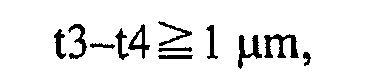


and
where
t1 is a thickness between a surface of the optical recording medium, and the first information recording surface closest to the surface of the optical recording medium,
t2 is a thickness between the first optical recording surface, and the second information recording surface second closest to the surface of the optical recording medium,
t3 is a thickness between the second optical recording surface, and the third information recording surface third closest to the surface of the optical recording medium, and
t4 is a thickness between the third optical recording surface, and the fourth information recording surface farthest from the surface of the optical recording medium. - The optical recording medium according to claim 1, wherein
the optical recording medium satisfies:


and
where
d1 is a distance from the surface of the optical recording medium to the first information recording surface,
d2 is a distance from the surface of the optical recording medium to the second information recording surface,
d3 is a distance from the surface of the optical recording medium to the third information recording surface,
d4 is a distance from the surface of the optical recording medium to the fourth information recording surface, and
E1, E2, E3, and E4 are respectively tolerances of the distances d1, d2, d3, and d4, the tolerances E1, E2, E3, and E4 each being set to 6 µm or less. - The optical recording medium according to claim 2, wherein
the tolerance E1 is set to 3 µm. - The optical recording medium according to claim 2 or 3, wherein
the tolerance E2 is set to 4.5 µm. - The optical recording medium according to any one of claims 1 through 4, wherein
the thickness t3 is set to 25.5 µm or less. - The optical recording medium according to any one of claims 1 through 4, wherein
the thickness t3 is set to 24.5 µm or less. - The optical recording medium according to any one of claims 1 through 6, wherein
the thickness t2 is set in a range of not smaller than 10.0 µm and not larger than 16.5 µm,
the thickness t3 is set in a range of not smaller than 14.5 µm and not larger than 24.5 µm, and
the thickness t4 is set in a range of not smaller than 11.0 µm and not larger than 20.5 µm. - The optical recording medium according to any one of claims 1 through 7, wherein
the distance d1 is set larger than 50 µm. - A method for producing an optical recording medium having four information recording surfaces, the method comprising:a step of forming, on a substrate, a light transmissive layer, a first information recording surface, a first intermediate layer, a second information recording surface, a second intermediate layer, a third information recording surface, a third intermediate layer, and a fourth information recording surface, whereinthe first through the fourth information recording surfaces, the first through the third intermediate layers, and the light transmissive layer are formed in such a manner that a thickness of the light transmissive layer and thicknesses of the first through the third intermediate layers satisfy:


and
wheret1 is the thickness of the light transmissive layer,t2 is the thickness of the first intermediate layer,t3 is the thickness of the second intermediate layer, andt4 is the thickness of the third intermediate layer. - The method for producing an optical recording medium according to claim 9, wherein
the optical recording medium produced by the method satisfies:t3-t4 ≧ 1 µm,t4-t2 ≧ µm,t2 ≧ 10 µm, andt1-(t2+t3+t4) ≧ 1 µm, whered2 is a distance from a surface of the optical recording medium to the second information recording surface,d3 is a distance from the surface of the optical recording medium to the third information recording surface, andd4 is a distance from the surface of the optical recording medium to the fourth information recording surface. - The method for producing an optical recording medium according to claim 10, wherein
the optical recording medium produced by the method satisfies:





and
- The method for producing an optical recording medium according to any one of claims 9 through 11, wherein
the first through the fourth information recording surfaces, the first through the third intermediate layers, and the light transmissive layer are so formed as to satisfy:a standard value of the thickness t1 is set to 53. 5 µm,a standard value of the thickness t2 is set to 11.5 µm,a standard value of the thickness t3 is set to 19.5 µm,a standard value of the thickness t4 is set to 15.5 µm, andtolerances of the thickness of the light transmissive layer and the thicknesses of the first through the third intermediate layers are each set to 1.5 µm or less. - An optical recording medium comprising three information recording surfaces, the optical recording medium satisfying:


and
where
t1 is a thickness between a surface of the optical recording medium, and the first information recording surface closest to the surface of the optical recording medium,
t2 is a thickness between the first optical recording surface, and the second information recording surface second closest to the surface of the optical recording medium, and
t3 is a thickness between the second optical recording surface, and the third information recording surface farthest from the surface of the optical recording medium. - The optical recording medium according to claim 13, wherein
the optical recording medium satisfies:


and
where
d2 is a distance from the surface of the optical recording medium to the second information recording surface, and
d3 is a distance from the surface of the optical recording medium to the third information recording surface. - A method for producing an optical recording medium having three information recording surfaces, the method comprising:a step of forming, on a substrate, a light transmissive layer, a first information recording surface, a first intermediate layer, a second information recording surface, a second intermediate layer, and a third information recording surface, whereinthe first through the third information recording surfaces, the first and the second intermediate layers, and the light transmissive layer are formed in such a manner that a thickness of the light transmissive layer and thicknesses of the first and the second intermediate layers satisfy:


and
wheret1 is the thickness of the light transmissive layer,t2 is the thickness of the first intermediate layer, andt3 is the thickness of the second intermediate layer. - The method for producing an optical recording medium according to claim 15, wherein
the optical recording medium produced by the method satisfies:
and
- The method for producing an optical recording medium according to claim 16, wherein
the optical recording medium produced by the method satisfies:


and
where
d2 is a distance from a surface of the optical recording medium to the second information recording surface, and
d3 is a distance from the surface of the optical recording medium to the third information recording surface. - The method for producing an optical recording medium according to any one of claims 15 through 17, wherein
the first through the third information recording surfaces, the first and the second intermediate layers, and the light transmissive layer are so formed as to satisfy:a standard value of the thickness t1 is set to 57.0 µm,a standard value of the thickness t2 is set to 18.0 µm,a standard value of the thickness t3 is set to 25.0 µm, andtolerances of the thickness of the light transmissive layer and the thicknesses of the first and the second intermediate layers are each set to 2.0 µm or less.
Applications Claiming Priority (2)
| Application Number | Priority Date | Filing Date | Title |
|---|---|---|---|
| US10601208P | 2008-10-16 | 2008-10-16 | |
| PCT/JP2009/005317 WO2010044245A1 (en) | 2008-10-16 | 2009-10-13 | Optical recording medium and method for manufacturing optical recording medium |
Publications (2)
| Publication Number | Publication Date |
|---|---|
| EP2337027A1 true EP2337027A1 (en) | 2011-06-22 |
| EP2337027A4 EP2337027A4 (en) | 2012-05-09 |
Family
ID=42106417
Family Applications (1)
| Application Number | Title | Priority Date | Filing Date |
|---|---|---|---|
| EP09820423A Withdrawn EP2337027A4 (en) | 2008-10-16 | 2009-10-13 | OPTICAL RECORDING MEDIUM AND METHOD FOR MANUFACTURING OPTICAL RECORDING MEDIUM |
Country Status (11)
| Country | Link |
|---|---|
| US (1) | US8206805B2 (en) |
| EP (1) | EP2337027A4 (en) |
| JP (1) | JP5411153B2 (en) |
| KR (1) | KR20110067010A (en) |
| CN (1) | CN102077283B (en) |
| AU (1) | AU2009304890B2 (en) |
| BR (1) | BRPI0914126A2 (en) |
| CA (1) | CA2729263A1 (en) |
| RU (1) | RU2509382C2 (en) |
| TW (1) | TWI470626B (en) |
| WO (1) | WO2010044245A1 (en) |
Families Citing this family (2)
| Publication number | Priority date | Publication date | Assignee | Title |
|---|---|---|---|---|
| WO2021145017A1 (en) * | 2020-01-15 | 2021-07-22 | パナソニックIpマネジメント株式会社 | Optical disk, manufacturing method thereof, optical information device, and information processing method |
| CN113391324B (en) * | 2021-06-28 | 2023-05-26 | 中国人民解放军92493部队计量测试研究所 | Target distance positioning system and positioning method |
Family Cites Families (12)
| Publication number | Priority date | Publication date | Assignee | Title |
|---|---|---|---|---|
| JP3918221B2 (en) | 1997-03-12 | 2007-05-23 | ソニー株式会社 | Protective film forming apparatus and protective film forming method |
| JP2001155380A (en) | 2000-10-27 | 2001-06-08 | Victor Co Of Japan Ltd | Optical recording medium |
| JP4215497B2 (en) * | 2002-12-27 | 2009-01-28 | Tdk株式会社 | Optical recording medium |
| US7289404B2 (en) * | 2003-03-13 | 2007-10-30 | Lg Electronics Inc. | Write-once recording medium and defective area management method and apparatus for write-once recording medium |
| JP2005285222A (en) * | 2004-03-30 | 2005-10-13 | Tdk Corp | Multilayer information recording medium manufacturing method and multilayer information recording medium manufacturing apparatus |
| WO2006009161A1 (en) * | 2004-07-21 | 2006-01-26 | Matsushita Electric Industrial Co., Ltd. | Multi-layer information recording medium and manufacturing method thereof |
| TW200611268A (en) * | 2004-09-30 | 2006-04-01 | Hitachi Maxell | Optical recording medium |
| CN101297363B (en) * | 2005-10-31 | 2010-11-17 | 松下电器产业株式会社 | Optical information recording medium and manufacturing method thereof |
| WO2008015974A1 (en) * | 2006-08-01 | 2008-02-07 | Panasonic Corporation | Optical recording medium and reproducing device |
| JP4994178B2 (en) | 2006-10-10 | 2012-08-08 | パナソニック株式会社 | Optical recording medium, information recording or reproducing method, and information recording or reproducing apparatus |
| US20080109837A1 (en) * | 2006-10-10 | 2008-05-08 | Joji Anzai | Optical recording medium, information recording or reproducing method, and information recording or reproducing apparatus |
| US7976922B2 (en) * | 2006-12-12 | 2011-07-12 | Ricoh Company, Ltd. | Optical recording medium |
-
2009
- 2009-10-13 KR KR1020107029845A patent/KR20110067010A/en not_active Abandoned
- 2009-10-13 AU AU2009304890A patent/AU2009304890B2/en not_active Expired - Fee Related
- 2009-10-13 RU RU2010153893/28A patent/RU2509382C2/en not_active IP Right Cessation
- 2009-10-13 CN CN2009801253762A patent/CN102077283B/en active Active
- 2009-10-13 JP JP2010533821A patent/JP5411153B2/en active Active
- 2009-10-13 EP EP09820423A patent/EP2337027A4/en not_active Withdrawn
- 2009-10-13 WO PCT/JP2009/005317 patent/WO2010044245A1/en not_active Ceased
- 2009-10-13 BR BRPI0914126A patent/BRPI0914126A2/en not_active IP Right Cessation
- 2009-10-13 CA CA2729263A patent/CA2729263A1/en not_active Abandoned
- 2009-10-15 TW TW98134891A patent/TWI470626B/en active
- 2009-10-16 US US12/580,721 patent/US8206805B2/en active Active
Also Published As
| Publication number | Publication date |
|---|---|
| AU2009304890A1 (en) | 2010-04-22 |
| US20100143637A1 (en) | 2010-06-10 |
| JPWO2010044245A1 (en) | 2012-03-15 |
| BRPI0914126A2 (en) | 2015-10-20 |
| TW201017656A (en) | 2010-05-01 |
| US8206805B2 (en) | 2012-06-26 |
| CN102077283B (en) | 2013-03-13 |
| RU2509382C2 (en) | 2014-03-10 |
| TWI470626B (en) | 2015-01-21 |
| JP5411153B2 (en) | 2014-02-12 |
| CN102077283A (en) | 2011-05-25 |
| RU2010153893A (en) | 2012-11-27 |
| CA2729263A1 (en) | 2010-04-22 |
| EP2337027A4 (en) | 2012-05-09 |
| WO2010044245A1 (en) | 2010-04-22 |
| KR20110067010A (en) | 2011-06-20 |
| AU2009304890B2 (en) | 2015-05-07 |
Similar Documents
| Publication | Publication Date | Title |
|---|---|---|
| JP4994178B2 (en) | Optical recording medium, information recording or reproducing method, and information recording or reproducing apparatus | |
| US8369200B2 (en) | Optical recording medium, and optical information device | |
| US8264944B2 (en) | Manufacturing method for optical recording medium, optical recording medium, optical information device, and information reproducing method | |
| US8259551B2 (en) | Optical recording medium, manufacturing method for optical recording medium, information recording/reproducing method and information recording/reproducing device | |
| EP2482280A1 (en) | Optical recording medium and method for manufacturing optical recording medium | |
| US8081551B2 (en) | Optical recording medium, and optical information device | |
| US20050078384A1 (en) | Objective lens for DVD/CD compatible optical pickup | |
| US8206805B2 (en) | Optical recording medium, and method for producing optical recording medium | |
| US8189452B2 (en) | Manufacturing method for optical recording medium, optical recording medium, optical information device, and information reproducing method | |
| US8233374B2 (en) | Multilayer optical disc | |
| EP1755116A2 (en) | Optical pickup apparatus capable of detecting and compensating for spherical aberration caused by thickness variation of recording layer | |
| US7298675B2 (en) | Multilayer recording medium and optical pickup for recording and/or reproducing the same | |
| EP1968055B1 (en) | Optical pick-up and disc apparatus having the same | |
| JP4419797B2 (en) | Optical pickup device | |
| WO2007048833A1 (en) | Optical scanning device |
Legal Events
| Date | Code | Title | Description |
|---|---|---|---|
| PUAI | Public reference made under article 153(3) epc to a published international application that has entered the european phase |
Free format text: ORIGINAL CODE: 0009012 |
|
| 17P | Request for examination filed |
Effective date: 20110512 |
|
| AK | Designated contracting states |
Kind code of ref document: A1 Designated state(s): AT BE BG CH CY CZ DE DK EE ES FI FR GB GR HR HU IE IS IT LI LT LU LV MC MK MT NL NO PL PT RO SE SI SK SM TR |
|
| AX | Request for extension of the european patent |
Extension state: AL BA RS |
|
| DAX | Request for extension of the european patent (deleted) | ||
| A4 | Supplementary search report drawn up and despatched |
Effective date: 20120405 |
|
| RIC1 | Information provided on ipc code assigned before grant |
Ipc: G11B 7/24 20060101AFI20120330BHEP |
|
| RAP1 | Party data changed (applicant data changed or rights of an application transferred) |
Owner name: PANASONIC CORPORATION Owner name: TDK CORPORATION Owner name: SONY CORPORATION |
|
| STAA | Information on the status of an ep patent application or granted ep patent |
Free format text: STATUS: THE APPLICATION HAS BEEN WITHDRAWN |
|
| 18W | Application withdrawn |
Effective date: 20150929 |