EP2336996A2 - Contactless infrared data transmission for wind turbines - Google Patents
Contactless infrared data transmission for wind turbines Download PDFInfo
- Publication number
- EP2336996A2 EP2336996A2 EP10193913A EP10193913A EP2336996A2 EP 2336996 A2 EP2336996 A2 EP 2336996A2 EP 10193913 A EP10193913 A EP 10193913A EP 10193913 A EP10193913 A EP 10193913A EP 2336996 A2 EP2336996 A2 EP 2336996A2
- Authority
- EP
- European Patent Office
- Prior art keywords
- wind turbine
- data
- data communication
- rotating portion
- pitch tube
- Prior art date
- Legal status (The legal status is an assumption and is not a legal conclusion. Google has not performed a legal analysis and makes no representation as to the accuracy of the status listed.)
- Granted
Links
Images


Classifications
-
- G—PHYSICS
- G08—SIGNALLING
- G08C—TRANSMISSION SYSTEMS FOR MEASURED VALUES, CONTROL OR SIMILAR SIGNALS
- G08C23/00—Non-electrical signal transmission systems, e.g. optical systems
- G08C23/04—Non-electrical signal transmission systems, e.g. optical systems using light waves, e.g. infrared
Definitions
- This invention relates generally to wind turbines, and more particularly to methods and apparatus for enabling transmission of data and signals between non-rotating portions of a wind turbine nacelle and a rotating hub.
- a conventional slipring is generally used to transmit discrete low voltage signals and to accommodate communication bus protocols between the stationary and rotational parts of a wind turbine. Sliprings are also used to transfer AC or DC power. Sliprings are based on a physical connection between the stationary and rotary structures, accomplished through electrically conductive sliding elements that are subject to wear-out, limiting the design life and reliability of the sliprings.
- Other techniques for enabling transmission of data between non-rotating portions of a wind turbine nacelle and a rotating hub may include use of fiber optic rotary joints, or use of wireless transmission, GSM mobile transmission, inductive coupling(s), or capacitive coupling(s).
- an apparatus for enabling transmission of signals and data via a means of infrared (IR) light for a wind turbine comprises a plurality of IR data communication elements configured to provide unidirectional or bidirectional IR data and signal exchange between a non-rotating portion of a wind turbine and a rotatable wind turbine hub in response to rotation of a rotating portion of the wind turbine.
- IR infrared
- a wind turbine 10 comprises a nacelle 11 housing a generator. Nacelle 11 is mounted atop a tall tower 12. Wind turbine 10 also comprises a rotor that includes one or more rotor blades 14, 15, 16 attached to a rotating hub 18. Although wind turbine 10 illustrated in Figure 1 includes three rotor blades 14, 15, 16, there are no specific limits on the number of rotor blades required by the embodiments described herein.
- various components are housed in nacelle 11 atop tower 12 of wind turbine 10.
- the height of tower 12 is selected based upon factors and conditions known in the art.
- one or more controllers including algorithmic software are used for wind-speed monitoring and turbine control and may be based on distributed or centralized control architectures.
- one or more variable blade pitch drive actuators are provided to control the pitch of blades 14, 15, 16.
- the pitches of blades 14, 15, 16 are individually controlled by the blade pitch actuators.
- the drive train of the wind turbine includes a main rotor shaft (also referred to as a "low speed shaft”) connected to the hub 18 via a main bearing and (in some configurations), at an opposite end of the rotor shaft to a gear box enumerated 22 in Figure 2 .
- the gear box 22 in some configurations, utilizes dual path geometry to drive an enclosed high speed shaft.
- the main rotor shaft is coupled directly to a generator.
- the high speed shaft is used to drive the generator.
- FIG. 2 illustrates a wind turbine data communication system 20 in which embodiments of the invention described below with reference to Figure 3 , are integrated therein.
- a pitch tube 24 is configured to rotate in coordination with the rotor hub 18 that rotates in response to wind contacting the rotor blades 14-16.
- the pitch tube 24 can be seen to pass through a gearbox 22 on its way to one or more rotary joints 40 that include a data or signal rotary joint 41 and a power rotary joint 42.
- the embodiments described herein relate only to data or signal transmission via means of infrared light and not to power transmission, and so apply only to the data or signal rotary joint portion of the rotary joints 40.
- the data/signal rotary joint 41 is configured to assist communication of data and signals between the rotor hub 18 and a topbox 28 that includes one or more low voltage data communication buses 30. Electrical power is transmitted via one or more power supply buses 32 while data communication signals are transmitted via one or more low voltage data communication buses 30.
- the pitch tube 24 is fixed to the hub 18, and the hub 18 is being rotated by the wind turbine blades 14, 15, 16, which are fixed to the hub 18.
- Pitch tube 24 is a commonly used term in wind industry for the pipe which guides the electrical cables from the hub 18 through the gearbox 22, where finally the slipring (or rotary joint(s)) 40 is mounted.
- the apparatus may or may not be connected to a pitch tube 24, and alternatively it is connected with the main shaft, or even directly with the hub 18. Important is only, that it is connected with a rotating element being part of the so-called hub 18 and being rotated with the same speed as the hub 18.
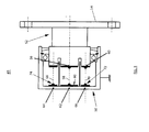
- FIG 3 illustrates a more detailed view of the data/signal rotary joint portion 41 of the wind turbine data communication system 20 depicted in Figure 2 , and shows infrared (IR) data communication elements 56, 60, 62, 64, 66 according to one embodiment.
- embodied rotary joint portion 41 includes a stationary section 50 where the data/signal bus 30 from the topbox 28 is connected.
- Rotary joint portion 41 further includes a rotating section 52 that is fixed to the rotatable pitch tube 24 via a flange 54.
- the present invention is not so limited however, and it can be appreciated that the IR joint does not necessarily need to be attached to the rotary power transmission element.
- the IR joint could, for example, be directly coupled to the pitch tube, in which case the rotary power transmission element(s) will be disposed behind the IR joint; or the IR joint could be coupled to the rotary power transmission element(s).
- Rotary joint portion 41 includes a transmitter IR diode 56 disposed on the central axis 58 of rotating section 52. At least one receiver IR diode 60 is disposed near an outer periphery of rotating section 52.
- Embodied stationary section 50 includes a receiver diode 62 disposed on the central axis 58 of the rotating section and configured to receive IR data signals transmitted via transmitter IR diode 56.
- One or more transmitter diodes 64, 66 are also disposed on stationary section 50. Each stationary section transmitter diode 64, 66 is configured to transmit a data IR signal in the direction of a corresponding signal transmission axis 68, 70.
- Each rotating section receiver IR diode 60 is configured to receive the IR data signals transmitted via the stationary section transmitter diodes 64, 66 along the corresponding signal transmission axes 68, 70. In this manner, bi-directional IR data transmission and reception takes place between the stationary section(s) 50 that forms a non-rotating portion of a wind turbine nacelle 11 according to one embodiment and a rotatable wind turbine hub 18 or corresponding pitch tube 24.
- the data transmission is achieved via infrared light, such as set forth according to well known communication standard IrDA-1.1. Standard components for infrared light emission and detection can be utilized for data transmission in wind turbines, where slip rings are conventionally used to achieve data transmission.
- the IR data transmission is achieved at the back end of the pitch tube 24 according to one embodiment so that at least one IR transmitter 56 and corresponding receiver 62 can be axially aligned with the central axis 58 of the pitch tube 24.
- Infrared diodes 64, 66, 60 are placed on a similar radius around the rotating axis 58, so that the diodes can see one another. These IR diodes radiate light with a certain opening angle of radiation, and there can be several diodes across the corresponding circumference, so rotation changes the corresponding diode communication with respect to time. Some misalignment or angular displacement between IR diodes 66 and 60 can be tolerated while achieving the desired data or signal transmission.
- the pitch tube 24 rotates with the rotor and hub 18 of the wind turbine 10 and provides a means for providing the hub 18 with electrical power and data communication signals.
- the continuous communication between a master controller unit 82 (PLC located inside the top box 28) and a slave unit pitch controller (typically located inside the hub 18) runs over a bi-direction and full-duplex network.
- IR technology provides a lower cost communication network with high reliability when compared to conventional slip rings. Further, this IR technology is simpler in structure to implement compared to glass fiber rotary joints, wireless transmission, GSM mobile transmission, inductive coupling and capacitive coupling techniques. Further, the IR technology advantageously protects the data communication link from damaging emi/emc effects.
- At least one IR data communication element 56, 60, 62, 64, 66 comprises a single or multi-wavelength IR device such as, without limitation, an IR diode that is configured to allow passage of IR data signals through predetermined device surface contaminants. Such contaminants may include, without limitation, fog, smoke, snow and even dirt and/or dust. At least one IR data communication element may be configured with a super-hydrophobic coating to protect a predetermined IR device from foul weather elements such as icing and/or rain.
- the lens or optical aperture of one or more of the IR data communication elements may be enhanced to provide a harsher operating environment tolerant element and may be configured to better collimate the IR emission of an IR device such as an IR diode, or to focus a narrow spot size on a targeted area.
- At least one IR data communication element 56, 60, 62, 64, 66 comprises a single or multi-wavelength IR device configured with an active surface heater 72 to remove moisture from optical surfaces.
- the IR data communication element may further include independently or in addition to the active surface heater, a rotating surface wiper 74 to provide a dusting effect on occasional or a regular rotational schedule.
- a shroud can independently or additionally be added to ingress points (enumerated 76 in Figure 2 ) in the pitch tube 24 to prevent solar blinding IR effects.
- Other embodiments may employ one or more single or multi-wavelength IR devices configured with a lens surface area to substantially fit the pitch tube signal area.
- the apparatus further comprises an adaptive IR link power budget monitor/controller 80 such as depicted in Figure 2 that is configured to control IR data signal power in response to predetermined IR data communication element conditions.
- IR data communication element conditions include, without limitation, surface contaminant build-up, misalignment, device wear, elastomer mount wearout, and vibration.
- rotary joint portion 41 includes microelectronics 80 integrated therein to control and enable usage of the IR diodes 56, 60, 62, 64, 66.
- the electronics is preferably located on the same circuit board as the IR diodes. Multiple functions can be achieved with the electronics, such as data integrity check via means of additional data protocols, adaptation to different bus interfaces (such as Ethernet, CANbus, USB), adaptation to different bus data rates, control of power consumption as mentioned above, or it could as well measure rotational speed.
- One basic function of the electronics 80 is to configure the electrical bus signal such that each diode produces suitable light pulses, and on the receiver side to amplify the signals and re-convert into suitable bus signals.
- Infrared light as used in this application shall be understood to mean electromagnetic waves with wavelength in the range of 780 nm to 1 mm.
- the IR light may or may not be coherent light, as produced by laser light diodes commonly used for fiber optic cables or fiber optic rotary joints.
- One typical embodiment of the apparatus comprises standard IR diodes with non-coherent light.
- the differentiator is the targeted distance between emitter and receiver: Where fiber optic joints are commonly designed for very small distances in the range of a few millimeters, the application here is intended for distances up to decimeters or even meters. A typical embodiment of the IR data joint as depicted in Figure 3 is designed for a distance between emitter and receiver in the range of centimeters.
Landscapes
- Physics & Mathematics (AREA)
- General Physics & Mathematics (AREA)
- Wind Motors (AREA)
- Optical Communication System (AREA)
- Arrangements For Transmission Of Measured Signals (AREA)
Abstract
Description
- This invention relates generally to wind turbines, and more particularly to methods and apparatus for enabling transmission of data and signals between non-rotating portions of a wind turbine nacelle and a rotating hub.
- A conventional slipring is generally used to transmit discrete low voltage signals and to accommodate communication bus protocols between the stationary and rotational parts of a wind turbine. Sliprings are also used to transfer AC or DC power. Sliprings are based on a physical connection between the stationary and rotary structures, accomplished through electrically conductive sliding elements that are subject to wear-out, limiting the design life and reliability of the sliprings.
- Other techniques for enabling transmission of data between non-rotating portions of a wind turbine nacelle and a rotating hub may include use of fiber optic rotary joints, or use of wireless transmission, GSM mobile transmission, inductive coupling(s), or capacitive coupling(s).
- It would be advantageous to provide methods and apparatus for enabling transmission of data and signals between non-rotating portions of a wind turbine nacelle and the rotating hub that are less expensive to manufacture or otherwise employ while achieving equal or greater reliability than methods and apparatus that require the use of fiber optic rotary joints, wireless transmission, GSM mobile transmission, inductive coupling(s), or capacitive coupling(s).
- According to one embodiment of the present invention, an apparatus for enabling transmission of signals and data via a means of infrared (IR) light for a wind turbine comprises a plurality of IR data communication elements configured to provide unidirectional or bidirectional IR data and signal exchange between a non-rotating portion of a wind turbine and a rotatable wind turbine hub in response to rotation of a rotating portion of the wind turbine.
- Various features, aspects, and advantages of the present invention will become better understood when the following detailed description is read with reference to the accompanying drawings in which like characters represent like parts throughout the drawings, wherein:
-
Figure 1 illustrates a wind turbine in which embodiments of the invention are integrated therein; -
Figure 2 is a simplified block diagram illustrating components in a wind turbine nacelle and hub for power and data communication systems in which embodiments of the invention are integrated therein; and -
Figure 3 illustrates a more detailed view of the rotary joint portion of the wind turbine signal and data communication system depicted inFigure 2 , showing infrared (IR) data communication elements according to one embodiment. - While the above-identified drawing figures set forth alternative embodiments, other embodiments of the present invention are also contemplated, as noted in the discussion. In all cases, this disclosure presents illustrated embodiments of the present invention by way of representation and not limitation. Numerous other modifications and embodiments can be devised by those skilled in the art which fall within the scope and spirit of the principles of this invention.
- In some configurations and referring to
Figure 1 , awind turbine 10 comprises anacelle 11 housing a generator. Nacelle 11 is mounted atop atall tower 12.Wind turbine 10 also comprises a rotor that includes one ormore rotor blades hub 18. Althoughwind turbine 10 illustrated inFigure 1 includes threerotor blades - In some configurations, various components are housed in
nacelle 11atop tower 12 ofwind turbine 10. The height oftower 12 is selected based upon factors and conditions known in the art. In some configurations, one or more controllers including algorithmic software are used for wind-speed monitoring and turbine control and may be based on distributed or centralized control architectures. - In some configurations, one or more variable blade pitch drive actuators are provided to control the pitch of
blades blades - The drive train of the wind turbine includes a main rotor shaft (also referred to as a "low speed shaft") connected to the
hub 18 via a main bearing and (in some configurations), at an opposite end of the rotor shaft to a gear box enumerated 22 inFigure 2 . The gear box 22, in some configurations, utilizes dual path geometry to drive an enclosed high speed shaft. In other configurations, the main rotor shaft is coupled directly to a generator. The high speed shaft is used to drive the generator. -
Figure 2 illustrates a wind turbinedata communication system 20 in which embodiments of the invention described below with reference toFigure 3 , are integrated therein. Apitch tube 24 is configured to rotate in coordination with therotor hub 18 that rotates in response to wind contacting the rotor blades 14-16. Thepitch tube 24 can be seen to pass through a gearbox 22 on its way to one or morerotary joints 40 that include a data orsignal rotary joint 41 and apower rotary joint 42. The embodiments described herein relate only to data or signal transmission via means of infrared light and not to power transmission, and so apply only to the data or signal rotary joint portion of therotary joints 40. The data/signal rotary joint 41 is configured to assist communication of data and signals between therotor hub 18 and atopbox 28 that includes one or more low voltagedata communication buses 30. Electrical power is transmitted via one or morepower supply buses 32 while data communication signals are transmitted via one or more low voltagedata communication buses 30. - More specifically, the
pitch tube 24 is fixed to thehub 18, and thehub 18 is being rotated by thewind turbine blades hub 18.Pitch tube 24 is a commonly used term in wind industry for the pipe which guides the electrical cables from thehub 18 through the gearbox 22, where finally the slipring (or rotary joint(s)) 40 is mounted. The apparatus may or may not be connected to apitch tube 24, and alternatively it is connected with the main shaft, or even directly with thehub 18. Important is only, that it is connected with a rotating element being part of the so-calledhub 18 and being rotated with the same speed as thehub 18. -
Figure 3 illustrates a more detailed view of the data/signal rotaryjoint portion 41 of the wind turbinedata communication system 20 depicted inFigure 2 , and shows infrared (IR)data communication elements rotary joint portion 41 includes astationary section 50 where the data/signal bus 30 from thetopbox 28 is connected.Rotary joint portion 41 further includes a rotatingsection 52 that is fixed to therotatable pitch tube 24 via aflange 54. The present invention is not so limited however, and it can be appreciated that the IR joint does not necessarily need to be attached to the rotary power transmission element. The IR joint could, for example, be directly coupled to the pitch tube, in which case the rotary power transmission element(s) will be disposed behind the IR joint; or the IR joint could be coupled to the rotary power transmission element(s). -
Rotary joint portion 41 includes atransmitter IR diode 56 disposed on thecentral axis 58 of rotatingsection 52. At least onereceiver IR diode 60 is disposed near an outer periphery of rotatingsection 52. Embodiedstationary section 50 includes areceiver diode 62 disposed on thecentral axis 58 of the rotating section and configured to receive IR data signals transmitted viatransmitter IR diode 56. One ormore transmitter diodes stationary section 50. Each stationarysection transmitter diode signal transmission axis receiver IR diode 60 is configured to receive the IR data signals transmitted via the stationarysection transmitter diodes signal transmission axes wind turbine nacelle 11 according to one embodiment and a rotatablewind turbine hub 18 orcorresponding pitch tube 24. - In summary explanation, an apparatus and method have been described for transmission of data between the non-rotating part of a
wind turbine nacelle 11 and a rotatinghub 18. The data transmission is achieved via infrared light, such as set forth according to well known communication standard IrDA-1.1. Standard components for infrared light emission and detection can be utilized for data transmission in wind turbines, where slip rings are conventionally used to achieve data transmission. The IR data transmission is achieved at the back end of thepitch tube 24 according to one embodiment so that at least oneIR transmitter 56 andcorresponding receiver 62 can be axially aligned with thecentral axis 58 of thepitch tube 24.Infrared diodes rotating axis 58, so that the diodes can see one another. These IR diodes radiate light with a certain opening angle of radiation, and there can be several diodes across the corresponding circumference, so rotation changes the corresponding diode communication with respect to time. Some misalignment or angular displacement betweenIR diodes pitch tube 24 rotates with the rotor andhub 18 of thewind turbine 10 and provides a means for providing thehub 18 with electrical power and data communication signals. The continuous communication between a master controller unit 82 (PLC located inside the top box 28) and a slave unit pitch controller (typically located inside the hub 18) runs over a bi-direction and full-duplex network. - The use of IR technology provides a lower cost communication network with high reliability when compared to conventional slip rings. Further, this IR technology is simpler in structure to implement compared to glass fiber rotary joints, wireless transmission, GSM mobile transmission, inductive coupling and capacitive coupling techniques. Further, the IR technology advantageously protects the data communication link from damaging emi/emc effects.
- According to one embodiment, at least one IR
data communication element - At least one IR
data communication element active surface heater 72 to remove moisture from optical surfaces. The IR data communication element may further include independently or in addition to the active surface heater, arotating surface wiper 74 to provide a dusting effect on occasional or a regular rotational schedule. A shroud can independently or additionally be added to ingress points (enumerated 76 inFigure 2 ) in thepitch tube 24 to prevent solar blinding IR effects. Other embodiments may employ one or more single or multi-wavelength IR devices configured with a lens surface area to substantially fit the pitch tube signal area. - According to one embodiment, the apparatus further comprises an adaptive IR link power budget monitor/
controller 80 such as depicted inFigure 2 that is configured to control IR data signal power in response to predetermined IR data communication element conditions. These conditions include, without limitation, surface contaminant build-up, misalignment, device wear, elastomer mount wearout, and vibration. - According to one embodiment, rotary
joint portion 41 includesmicroelectronics 80 integrated therein to control and enable usage of theIR diodes electronics 80 is to configure the electrical bus signal such that each diode produces suitable light pulses, and on the receiver side to amplify the signals and re-convert into suitable bus signals. - Infrared light as used in this application shall be understood to mean electromagnetic waves with wavelength in the range of 780 nm to 1 mm. The IR light may or may not be coherent light, as produced by laser light diodes commonly used for fiber optic cables or fiber optic rotary joints. One typical embodiment of the apparatus comprises standard IR diodes with non-coherent light.
- Even if the wavelength of the light is in the same range as for fiber optic rotary joints, the differentiator is the targeted distance between emitter and receiver: Where fiber optic joints are commonly designed for very small distances in the range of a few millimeters, the application here is intended for distances up to decimeters or even meters. A typical embodiment of the IR data joint as depicted in
Figure 3 is designed for a distance between emitter and receiver in the range of centimeters. - While the invention has been described in terms of various specific embodiments, those skilled in the art will recognize that the invention can be practiced with modification within the spirit and scope of the claims.
- Various aspects and embodiments of the present invention are defined by the following numbered clauses:
- 1. An apparatus for enabling transmission of signals and data via a means of infrared (IR) light for a wind turbine, the apparatus comprising a plurality of IR data communication elements configured to provide unidirectional or bidirectional IR data and signal exchange between a non-rotating portion of a wind turbine and a rotatable wind turbine hub in response to rotation of a rotating portion of the wind turbine.
- 2. The apparatus according to clause, wherein the non-rotating portion comprises a non-rotating portion of a wind turbine nacelle.
- 3. The apparatus according to any preceding clause, wherein the rotating portion of the wind turbine comprises a pitch tube.
- 4. The apparatus according to any preceding clause, wherein the rotating portion of the wind turbine comprises the rotatable wind turbine hub.
- 5. The apparatus according to any preceding clause, wherein at least one IR data communication element comprises an IR-diode.
- 6. The apparatus according to any preceding clause, wherein at least one IR data communication element is configured to transmit or receive IR data signals along a central axis of the pitch tube.
- 7. The apparatus according to any preceding clause, wherein at least one IR data communication element is configured to transmit IR data signals along a path independent of the central axis of the pitch tube.
- 8. The apparatus according to any preceding clause, further comprising a data communication bus configured to communicate the bi-directional data between the non-rotating portion of the wind turbine and the rotatable wind turbine hub.
- 9. The apparatus according to any preceding clause, wherein at least one IR data communication element comprises a single or multi-wavelength IR device configured to allow passage of IR data signals through predetermined device surface contaminants.
- 10. The apparatus according to any preceding clause, wherein at least one IR data communication element comprises a single or multi-wavelength IR device configured with an active surface heater to remove moisture from optical surfaces.
- 11. The apparatus according to any preceding clause, wherein at least one IR data communication element comprises a single or multi-wavelength IR device configured with a super-hydrophobic coating to protect a predetermined IR device from foul weather elements.
- 12. The apparatus according to any preceding clause, wherein the foul weather elements comprise at least one of ice and rain.
- 13. The apparatus according to any preceding clause, wherein at least one IR data communication element comprises a single or multi-wavelength IR device configured with a lens surface area to substantially fit the pitch tube signal area.
- 14. The apparatus according to any preceding clause, further comprising microelectronics configured to drive and operate the IR communication elements.
- 15. The apparatus according to any preceding clause, wherein the microelectronics are further configured to achieve one or more of a data integrity check via means of predetermined data protocols, adaptation to different bus interfaces (such as Ethernet, CANbus, USB), adaptation to different bus data rates, control of IR power consumption, and measurement of rotational speed.
- 16. The apparatus according to any preceding clause, further comprising an adaptive IR link power budget monitor configured to control IR data signal power in response to predetermined IR data communication element conditions.
- 17. The apparatus according to any preceding clause, wherein the predetermined IR data communication elements conditions comprise at least one of surface contaminant build-up, miss-alignment, device wear, elastomer mount wearout, and vibration.
- 18. The apparatus according to any preceding clause, wherein the plurality of IR data communication elements comprise at least one receiver IR element spaced apart from at least one corresponding transmitter IR element at a distance greater than about 1 centimeter.
- 19. The apparatus according to any preceding clause, wherein the plurality of IR data communication elements are connected to at least one of a pitch tube, a main shaft, and the rotatable hub.
Claims (10)
- An apparatus (41) for enabling transmission of signals and data via a means of infrared (IR) light for a wind turbine, the apparatus (41) comprising a plurality of IR data communication elements (56,60,62,64,66) configured to provide unidirectional or bidirectional IR data and signal exchange between a non-rotating portion (50) of a wind turbine and a rotatable wind turbine hub in response to rotation of a rotating portion (52) of the wind turbine.
- The apparatus (41) according to claim 1, wherein the non-rotating portion (50) comprises a non-rotating portion of a wind turbine nacelle.
- The apparatus (41) according to any preceding claim, wherein the rotating portion (52) of the wind turbine comprises a pitch tube.
- The apparatus (41) according to any preceding claim, wherein at least one IR data communication element (56,60,62,64,66) is configured to transmit or receive IR data signals along a central axis (58) of the pitch tube.
- The apparatus (41) according to any preceding claim, wherein at least one IR data communication element (56,60,62,64,66) is configured to transmit IR data signals along a path (68), (70) independent of the central axis (58) of the pitch tube.
- The apparatus (41) according to any preceding claim, wherein at least one IR data communication element (56,60,62,64,66) comprises a single or multi-wavelength IR device configured with an active surface heater to remove moisture from optical surfaces.
- The apparatus (41) according to any preceding claim, wherein at least one IR data communication element (56,60,62,64,66) comprises a single or multi-wavelength IR device configured with a super-hydrophobic coating to protect a predetermined IR device from foul weather elements.
- The apparatus (41) according to any preceding claim, wherein at least one IR data communication element (56,60,62,64,66) comprises a single or multi-wavelength IR device configured with a lens surface area to substantially fit the pitch tube signal area.
- The apparatus (41) according to any preceding claim, further comprising microelectronics (81) configured to drive and operate the IR communication elements (56,60,62,64,66).
- The apparatus (41) according to any preceding claim, wherein the plurality of IR data communication elements (56,60,62,64,66) comprise at least one receiver IR element (62) spaced apart from at least one corresponding transmitter IR element (56) at a distance greater than about 1 centimeter.
Applications Claiming Priority (1)
| Application Number | Priority Date | Filing Date | Title |
|---|---|---|---|
| US12/642,981 US8041225B2 (en) | 2009-12-21 | 2009-12-21 | Contactless infrared data transmission for wind turbines |
Publications (3)
| Publication Number | Publication Date |
|---|---|
| EP2336996A2 true EP2336996A2 (en) | 2011-06-22 |
| EP2336996A3 EP2336996A3 (en) | 2011-09-28 |
| EP2336996B1 EP2336996B1 (en) | 2019-02-27 |
Family
ID=43836690
Family Applications (1)
| Application Number | Title | Priority Date | Filing Date |
|---|---|---|---|
| EP10193913.0A Active EP2336996B1 (en) | 2009-12-21 | 2010-12-07 | Contactless infrared data transmission for wind turbines |
Country Status (3)
| Country | Link |
|---|---|
| US (1) | US8041225B2 (en) |
| EP (1) | EP2336996B1 (en) |
| CN (1) | CN102103793B (en) |
Cited By (1)
| Publication number | Priority date | Publication date | Assignee | Title |
|---|---|---|---|---|
| EP3163070A1 (en) * | 2015-10-30 | 2017-05-03 | Nordex Energy GmbH | Wind turbine with a slip ring transmitter |
Families Citing this family (10)
| Publication number | Priority date | Publication date | Assignee | Title |
|---|---|---|---|---|
| US8067847B1 (en) * | 2010-12-16 | 2011-11-29 | General Electric Company | Variable speed machine assembly and method for making the same |
| US20130092786A1 (en) * | 2011-10-13 | 2013-04-18 | Sikorsky Aircraft Corporation | Interferometric strain field sensor system for measuring rotor state |
| US20130147201A1 (en) * | 2011-12-13 | 2013-06-13 | Robert Roesner | Contactless power transfer device and method |
| DE102015201019A1 (en) * | 2015-01-22 | 2016-07-28 | Wobben Properties Gmbh | Wind turbine and wind turbine bus system |
| JP6467331B2 (en) * | 2015-02-16 | 2019-02-13 | 太陽誘電株式会社 | Optical signal transmission device and electronic device using the same |
| US10042042B2 (en) * | 2015-06-12 | 2018-08-07 | Aero Vironment, Inc. | Rotating lidar |
| US20160376917A1 (en) * | 2015-06-29 | 2016-12-29 | Siemens Energy, Inc. | Method and an apparatus for measuring a deflection of a rotor of a turbomachine |
| JP7604163B2 (en) * | 2020-10-14 | 2024-12-23 | キヤノン株式会社 | Wireless transmission system, control method, and program |
| JP7630967B2 (en) * | 2020-11-17 | 2025-02-18 | キヤノン株式会社 | Wireless transmission system, control method, and program |
| EP4500742B1 (en) * | 2022-03-28 | 2025-11-05 | Vestas Wind Systems A/S | Wind turbine with control network and monitoring network |
Family Cites Families (18)
| Publication number | Priority date | Publication date | Assignee | Title |
|---|---|---|---|---|
| JPH05151491A (en) | 1991-11-29 | 1993-06-18 | Mitsubishi Heavy Ind Ltd | Non-contact signal transferring device in paper feeder |
| DE4428790C1 (en) * | 1994-08-13 | 1996-02-22 | Bfi Betriebstechnik Gmbh | Bidirectional information transmission appts. for telemetry communication through rotor-stator arrangement |
| US6031949A (en) * | 1996-03-27 | 2000-02-29 | Forfas | Optical data communication system |
| JP3241315B2 (en) | 1997-12-25 | 2001-12-25 | 千蔵工業株式会社 | Revolving door |
| JP2002026589A (en) | 2000-07-07 | 2002-01-25 | Matsushita Electric Ind Co Ltd | Component mounting machine |
| US6759759B2 (en) * | 2000-08-29 | 2004-07-06 | Tamagawa Seiki Kabushiki Kaisha | Rotary contactless connector and non-rotary contactless connector |
| US6643519B1 (en) * | 2000-10-24 | 2003-11-04 | At&T Corp. | Transmitter power control method and apparatus |
| JP2003168184A (en) | 2001-11-30 | 2003-06-13 | Resuka:Kk | Wireless sensor |
| US7295592B2 (en) * | 2002-03-08 | 2007-11-13 | Sharp Kabushiki Kaisha | Light source device and optical communication module employing the device |
| JP4202351B2 (en) * | 2005-09-27 | 2008-12-24 | 中部日本マルコ株式会社 | Non-contact connector |
| US7218012B1 (en) * | 2006-05-31 | 2007-05-15 | General Electric Company | Emergency pitch drive power supply |
| US20080147240A1 (en) | 2006-12-19 | 2008-06-19 | Gambro Bct Inc. | Apparatus for separating a composite liquid with process control on a centrifuge rotor |
| DE102007024210A1 (en) * | 2007-05-15 | 2008-11-27 | Pilz Gmbh & Co. Kg | Optoelectronic sensor to protect a hazardous area |
| DK2176545T3 (en) * | 2007-07-12 | 2014-12-15 | Windurance Llc | Method and apparatus for nettabs-flow for wind turbine pitch-management system |
| AU2008287128B2 (en) * | 2007-08-10 | 2013-07-18 | Janssen Biotech, Inc. | Immunoglobulin cleavage fragments as disease indicators and compositions for detecting and binding such |
| EP2205862A2 (en) * | 2007-10-15 | 2010-07-14 | Suzion Energy GmbH | Wind energy installation with enhanced overvoltage protection |
| US8202050B2 (en) * | 2008-05-09 | 2012-06-19 | General Electric Company | Wind turbine with wireless pitch control |
| US20100148505A1 (en) * | 2008-12-16 | 2010-06-17 | Dunlap Gregory M | Contact-less power and signal transmission device for a high power level transformer |
-
2009
- 2009-12-21 US US12/642,981 patent/US8041225B2/en active Active
-
2010
- 2010-12-07 EP EP10193913.0A patent/EP2336996B1/en active Active
- 2010-12-21 CN CN201010620935.1A patent/CN102103793B/en active Active
Non-Patent Citations (1)
| Title |
|---|
| None |
Cited By (1)
| Publication number | Priority date | Publication date | Assignee | Title |
|---|---|---|---|---|
| EP3163070A1 (en) * | 2015-10-30 | 2017-05-03 | Nordex Energy GmbH | Wind turbine with a slip ring transmitter |
Also Published As
| Publication number | Publication date |
|---|---|
| CN102103793B (en) | 2014-12-31 |
| US20110150497A1 (en) | 2011-06-23 |
| CN102103793A (en) | 2011-06-22 |
| EP2336996A3 (en) | 2011-09-28 |
| EP2336996B1 (en) | 2019-02-27 |
| US8041225B2 (en) | 2011-10-18 |
Similar Documents
| Publication | Publication Date | Title |
|---|---|---|
| US8041225B2 (en) | Contactless infrared data transmission for wind turbines | |
| CA2589803C (en) | Rotor blade for a wind power station | |
| US8393993B2 (en) | Wind turbine comprising at least one gearbox and an epicyclic gearbox | |
| US20120207589A1 (en) | Detection of ice on airfoils | |
| WO2012089212A1 (en) | Global wind farm surveillance systems using fiber optic sensors | |
| KR20200062880A (en) | Robot for Removing Ice And Snow on Transmission Line | |
| JP2018520371A (en) | Rotating lidar | |
| US20180191404A1 (en) | Interface for transferring power and data between a non-rotating body and a rotating body | |
| CN107429818A (en) | The measuring system and measuring method of the variable on planet carrier for detecting epicyclic transmission mechanism | |
| CN109844309A (en) | The method and system that the rotor blade of wind turbine rotor is safeguarded | |
| CN101576050A (en) | Wind turbine with wireless pitch control | |
| EP2384017A2 (en) | Method for measuring an operational parameter of a wind turbine and measurement device | |
| WO2011136707A1 (en) | Helicopter obstacle detection and information system | |
| WO2010015359A1 (en) | Electrical power provision to a rotatable assembly | |
| US11698130B2 (en) | Gearbox including wireless sensors | |
| KR101215507B1 (en) | Lightning protection device for wind generator | |
| WO2011114445A1 (en) | Wind power generator | |
| KR101387749B1 (en) | Rotor lock control system and method of wind turbine | |
| CN213582549U (en) | A wind turbine communication device | |
| US10742088B2 (en) | Support assembly for rotating body | |
| WO2020200725A1 (en) | Energy supply for sensors in a wind turbine | |
| CN205664813U (en) | Laser distance measurement device | |
| US10656342B2 (en) | Optical wireless rotary joint | |
| CN223648958U (en) | An airborne servo turntable | |
| CN223934951U (en) | Propeller pitch control system, motor-generator, electric propulsion device and aircraft |
Legal Events
| Date | Code | Title | Description |
|---|---|---|---|
| PUAI | Public reference made under article 153(3) epc to a published international application that has entered the european phase |
Free format text: ORIGINAL CODE: 0009012 |
|
| AK | Designated contracting states |
Kind code of ref document: A2 Designated state(s): AL AT BE BG CH CY CZ DE DK EE ES FI FR GB GR HR HU IE IS IT LI LT LU LV MC MK MT NL NO PL PT RO RS SE SI SK SM TR |
|
| AX | Request for extension of the european patent |
Extension state: BA ME |
|
| PUAL | Search report despatched |
Free format text: ORIGINAL CODE: 0009013 |
|
| AK | Designated contracting states |
Kind code of ref document: A3 Designated state(s): AL AT BE BG CH CY CZ DE DK EE ES FI FR GB GR HR HU IE IS IT LI LT LU LV MC MK MT NL NO PL PT RO RS SE SI SK SM TR |
|
| AX | Request for extension of the european patent |
Extension state: BA ME |
|
| RIC1 | Information provided on ipc code assigned before grant |
Ipc: G08C 23/04 20060101AFI20110822BHEP |
|
| 17P | Request for examination filed |
Effective date: 20120328 |
|
| STAA | Information on the status of an ep patent application or granted ep patent |
Free format text: STATUS: EXAMINATION IS IN PROGRESS |
|
| 17Q | First examination report despatched |
Effective date: 20170303 |
|
| GRAP | Despatch of communication of intention to grant a patent |
Free format text: ORIGINAL CODE: EPIDOSNIGR1 |
|
| STAA | Information on the status of an ep patent application or granted ep patent |
Free format text: STATUS: GRANT OF PATENT IS INTENDED |
|
| INTG | Intention to grant announced |
Effective date: 20181030 |
|
| GRAS | Grant fee paid |
Free format text: ORIGINAL CODE: EPIDOSNIGR3 |
|
| GRAA | (expected) grant |
Free format text: ORIGINAL CODE: 0009210 |
|
| STAA | Information on the status of an ep patent application or granted ep patent |
Free format text: STATUS: THE PATENT HAS BEEN GRANTED |
|
| AK | Designated contracting states |
Kind code of ref document: B1 Designated state(s): AL AT BE BG CH CY CZ DE DK EE ES FI FR GB GR HR HU IE IS IT LI LT LU LV MC MK MT NL NO PL PT RO RS SE SI SK SM TR |
|
| REG | Reference to a national code |
Ref country code: GB Ref legal event code: FG4D |
|
| REG | Reference to a national code |
Ref country code: CH Ref legal event code: EP |
|
| REG | Reference to a national code |
Ref country code: AT Ref legal event code: REF Ref document number: 1102481 Country of ref document: AT Kind code of ref document: T Effective date: 20190315 |
|
| REG | Reference to a national code |
Ref country code: IE Ref legal event code: FG4D |
|
| REG | Reference to a national code |
Ref country code: DE Ref legal event code: R096 Ref document number: 602010057188 Country of ref document: DE |
|
| REG | Reference to a national code |
Ref country code: NL Ref legal event code: MP Effective date: 20190227 |
|
| REG | Reference to a national code |
Ref country code: LT Ref legal event code: MG4D |
|
| PG25 | Lapsed in a contracting state [announced via postgrant information from national office to epo] |
Ref country code: LT Free format text: LAPSE BECAUSE OF FAILURE TO SUBMIT A TRANSLATION OF THE DESCRIPTION OR TO PAY THE FEE WITHIN THE PRESCRIBED TIME-LIMIT Effective date: 20190227 Ref country code: NL Free format text: LAPSE BECAUSE OF FAILURE TO SUBMIT A TRANSLATION OF THE DESCRIPTION OR TO PAY THE FEE WITHIN THE PRESCRIBED TIME-LIMIT Effective date: 20190227 Ref country code: FI Free format text: LAPSE BECAUSE OF FAILURE TO SUBMIT A TRANSLATION OF THE DESCRIPTION OR TO PAY THE FEE WITHIN THE PRESCRIBED TIME-LIMIT Effective date: 20190227 Ref country code: SE Free format text: LAPSE BECAUSE OF FAILURE TO SUBMIT A TRANSLATION OF THE DESCRIPTION OR TO PAY THE FEE WITHIN THE PRESCRIBED TIME-LIMIT Effective date: 20190227 Ref country code: NO Free format text: LAPSE BECAUSE OF FAILURE TO SUBMIT A TRANSLATION OF THE DESCRIPTION OR TO PAY THE FEE WITHIN THE PRESCRIBED TIME-LIMIT Effective date: 20190527 Ref country code: PT Free format text: LAPSE BECAUSE OF FAILURE TO SUBMIT A TRANSLATION OF THE DESCRIPTION OR TO PAY THE FEE WITHIN THE PRESCRIBED TIME-LIMIT Effective date: 20190627 |
|
| PG25 | Lapsed in a contracting state [announced via postgrant information from national office to epo] |
Ref country code: LV Free format text: LAPSE BECAUSE OF FAILURE TO SUBMIT A TRANSLATION OF THE DESCRIPTION OR TO PAY THE FEE WITHIN THE PRESCRIBED TIME-LIMIT Effective date: 20190227 Ref country code: IS Free format text: LAPSE BECAUSE OF FAILURE TO SUBMIT A TRANSLATION OF THE DESCRIPTION OR TO PAY THE FEE WITHIN THE PRESCRIBED TIME-LIMIT Effective date: 20190627 Ref country code: GR Free format text: LAPSE BECAUSE OF FAILURE TO SUBMIT A TRANSLATION OF THE DESCRIPTION OR TO PAY THE FEE WITHIN THE PRESCRIBED TIME-LIMIT Effective date: 20190528 Ref country code: RS Free format text: LAPSE BECAUSE OF FAILURE TO SUBMIT A TRANSLATION OF THE DESCRIPTION OR TO PAY THE FEE WITHIN THE PRESCRIBED TIME-LIMIT Effective date: 20190227 Ref country code: HR Free format text: LAPSE BECAUSE OF FAILURE TO SUBMIT A TRANSLATION OF THE DESCRIPTION OR TO PAY THE FEE WITHIN THE PRESCRIBED TIME-LIMIT Effective date: 20190227 Ref country code: BG Free format text: LAPSE BECAUSE OF FAILURE TO SUBMIT A TRANSLATION OF THE DESCRIPTION OR TO PAY THE FEE WITHIN THE PRESCRIBED TIME-LIMIT Effective date: 20190527 |
|
| REG | Reference to a national code |
Ref country code: AT Ref legal event code: MK05 Ref document number: 1102481 Country of ref document: AT Kind code of ref document: T Effective date: 20190227 |
|
| PG25 | Lapsed in a contracting state [announced via postgrant information from national office to epo] |
Ref country code: AL Free format text: LAPSE BECAUSE OF FAILURE TO SUBMIT A TRANSLATION OF THE DESCRIPTION OR TO PAY THE FEE WITHIN THE PRESCRIBED TIME-LIMIT Effective date: 20190227 Ref country code: ES Free format text: LAPSE BECAUSE OF FAILURE TO SUBMIT A TRANSLATION OF THE DESCRIPTION OR TO PAY THE FEE WITHIN THE PRESCRIBED TIME-LIMIT Effective date: 20190227 Ref country code: CZ Free format text: LAPSE BECAUSE OF FAILURE TO SUBMIT A TRANSLATION OF THE DESCRIPTION OR TO PAY THE FEE WITHIN THE PRESCRIBED TIME-LIMIT Effective date: 20190227 Ref country code: RO Free format text: LAPSE BECAUSE OF FAILURE TO SUBMIT A TRANSLATION OF THE DESCRIPTION OR TO PAY THE FEE WITHIN THE PRESCRIBED TIME-LIMIT Effective date: 20190227 Ref country code: SK Free format text: LAPSE BECAUSE OF FAILURE TO SUBMIT A TRANSLATION OF THE DESCRIPTION OR TO PAY THE FEE WITHIN THE PRESCRIBED TIME-LIMIT Effective date: 20190227 Ref country code: DK Free format text: LAPSE BECAUSE OF FAILURE TO SUBMIT A TRANSLATION OF THE DESCRIPTION OR TO PAY THE FEE WITHIN THE PRESCRIBED TIME-LIMIT Effective date: 20190227 Ref country code: EE Free format text: LAPSE BECAUSE OF FAILURE TO SUBMIT A TRANSLATION OF THE DESCRIPTION OR TO PAY THE FEE WITHIN THE PRESCRIBED TIME-LIMIT Effective date: 20190227 Ref country code: IT Free format text: LAPSE BECAUSE OF FAILURE TO SUBMIT A TRANSLATION OF THE DESCRIPTION OR TO PAY THE FEE WITHIN THE PRESCRIBED TIME-LIMIT Effective date: 20190227 |
|
| REG | Reference to a national code |
Ref country code: DE Ref legal event code: R097 Ref document number: 602010057188 Country of ref document: DE |
|
| PG25 | Lapsed in a contracting state [announced via postgrant information from national office to epo] |
Ref country code: SM Free format text: LAPSE BECAUSE OF FAILURE TO SUBMIT A TRANSLATION OF THE DESCRIPTION OR TO PAY THE FEE WITHIN THE PRESCRIBED TIME-LIMIT Effective date: 20190227 Ref country code: PL Free format text: LAPSE BECAUSE OF FAILURE TO SUBMIT A TRANSLATION OF THE DESCRIPTION OR TO PAY THE FEE WITHIN THE PRESCRIBED TIME-LIMIT Effective date: 20190227 |
|
| PG25 | Lapsed in a contracting state [announced via postgrant information from national office to epo] |
Ref country code: AT Free format text: LAPSE BECAUSE OF FAILURE TO SUBMIT A TRANSLATION OF THE DESCRIPTION OR TO PAY THE FEE WITHIN THE PRESCRIBED TIME-LIMIT Effective date: 20190227 |
|
| PLBE | No opposition filed within time limit |
Free format text: ORIGINAL CODE: 0009261 |
|
| STAA | Information on the status of an ep patent application or granted ep patent |
Free format text: STATUS: NO OPPOSITION FILED WITHIN TIME LIMIT |
|
| 26N | No opposition filed |
Effective date: 20191128 |
|
| PG25 | Lapsed in a contracting state [announced via postgrant information from national office to epo] |
Ref country code: SI Free format text: LAPSE BECAUSE OF FAILURE TO SUBMIT A TRANSLATION OF THE DESCRIPTION OR TO PAY THE FEE WITHIN THE PRESCRIBED TIME-LIMIT Effective date: 20190227 |
|
| PG25 | Lapsed in a contracting state [announced via postgrant information from national office to epo] |
Ref country code: TR Free format text: LAPSE BECAUSE OF FAILURE TO SUBMIT A TRANSLATION OF THE DESCRIPTION OR TO PAY THE FEE WITHIN THE PRESCRIBED TIME-LIMIT Effective date: 20190227 |
|
| REG | Reference to a national code |
Ref country code: CH Ref legal event code: PL |
|
| REG | Reference to a national code |
Ref country code: BE Ref legal event code: MM Effective date: 20191231 |
|
| PG25 | Lapsed in a contracting state [announced via postgrant information from national office to epo] |
Ref country code: MC Free format text: LAPSE BECAUSE OF FAILURE TO SUBMIT A TRANSLATION OF THE DESCRIPTION OR TO PAY THE FEE WITHIN THE PRESCRIBED TIME-LIMIT Effective date: 20190227 |
|
| GBPC | Gb: european patent ceased through non-payment of renewal fee |
Effective date: 20191207 |
|
| PG25 | Lapsed in a contracting state [announced via postgrant information from national office to epo] |
Ref country code: LU Free format text: LAPSE BECAUSE OF NON-PAYMENT OF DUE FEES Effective date: 20191207 Ref country code: IE Free format text: LAPSE BECAUSE OF NON-PAYMENT OF DUE FEES Effective date: 20191207 Ref country code: GB Free format text: LAPSE BECAUSE OF NON-PAYMENT OF DUE FEES Effective date: 20191207 Ref country code: FR Free format text: LAPSE BECAUSE OF NON-PAYMENT OF DUE FEES Effective date: 20191231 |
|
| PG25 | Lapsed in a contracting state [announced via postgrant information from national office to epo] |
Ref country code: CH Free format text: LAPSE BECAUSE OF NON-PAYMENT OF DUE FEES Effective date: 20191231 Ref country code: BE Free format text: LAPSE BECAUSE OF NON-PAYMENT OF DUE FEES Effective date: 20191231 Ref country code: LI Free format text: LAPSE BECAUSE OF NON-PAYMENT OF DUE FEES Effective date: 20191231 |
|
| PG25 | Lapsed in a contracting state [announced via postgrant information from national office to epo] |
Ref country code: CY Free format text: LAPSE BECAUSE OF FAILURE TO SUBMIT A TRANSLATION OF THE DESCRIPTION OR TO PAY THE FEE WITHIN THE PRESCRIBED TIME-LIMIT Effective date: 20190227 |
|
| PG25 | Lapsed in a contracting state [announced via postgrant information from national office to epo] |
Ref country code: HU Free format text: LAPSE BECAUSE OF FAILURE TO SUBMIT A TRANSLATION OF THE DESCRIPTION OR TO PAY THE FEE WITHIN THE PRESCRIBED TIME-LIMIT; INVALID AB INITIO Effective date: 20101207 Ref country code: MT Free format text: LAPSE BECAUSE OF FAILURE TO SUBMIT A TRANSLATION OF THE DESCRIPTION OR TO PAY THE FEE WITHIN THE PRESCRIBED TIME-LIMIT Effective date: 20190227 |
|
| PG25 | Lapsed in a contracting state [announced via postgrant information from national office to epo] |
Ref country code: MK Free format text: LAPSE BECAUSE OF FAILURE TO SUBMIT A TRANSLATION OF THE DESCRIPTION OR TO PAY THE FEE WITHIN THE PRESCRIBED TIME-LIMIT Effective date: 20190227 |
|
| P01 | Opt-out of the competence of the unified patent court (upc) registered |
Effective date: 20230530 |
|
| REG | Reference to a national code |
Ref country code: DE Ref legal event code: R082 Ref document number: 602010057188 Country of ref document: DE Ref country code: DE Ref legal event code: R081 Ref document number: 602010057188 Country of ref document: DE Owner name: GENERAL ELECTRIC RENOVABLES ESPANA, S.L., ES Free format text: FORMER OWNER: GENERAL ELECTRIC COMPANY, SCHENECTADY, NY, US |
|
| PGFP | Annual fee paid to national office [announced via postgrant information from national office to epo] |
Ref country code: DE Payment date: 20251126 Year of fee payment: 16 |