EP2336919A1 - Method and system for developing a hybrid gas turbine engine state variable model - Google Patents
Method and system for developing a hybrid gas turbine engine state variable model Download PDFInfo
- Publication number
- EP2336919A1 EP2336919A1 EP10011544A EP10011544A EP2336919A1 EP 2336919 A1 EP2336919 A1 EP 2336919A1 EP 10011544 A EP10011544 A EP 10011544A EP 10011544 A EP10011544 A EP 10011544A EP 2336919 A1 EP2336919 A1 EP 2336919A1
- Authority
- EP
- European Patent Office
- Prior art keywords
- engine
- model
- estimated
- residuals
- parameters
- Prior art date
- Legal status (The legal status is an assumption and is not a legal conclusion. Google has not performed a legal analysis and makes no representation as to the accuracy of the status listed.)
- Granted
Links
- 238000000034 method Methods 0.000 title claims abstract description 13
- 238000013528 artificial neural network Methods 0.000 claims abstract description 19
- 239000013598 vector Substances 0.000 claims description 9
- 238000003062 neural network model Methods 0.000 claims 1
- 238000012549 training Methods 0.000 abstract description 10
- 238000011161 development Methods 0.000 description 4
- 238000012360 testing method Methods 0.000 description 4
- 230000015572 biosynthetic process Effects 0.000 description 2
- 238000012937 correction Methods 0.000 description 2
- 238000013461 design Methods 0.000 description 2
- 230000000694 effects Effects 0.000 description 2
- 239000000446 fuel Substances 0.000 description 2
- 238000012986 modification Methods 0.000 description 2
- 230000004048 modification Effects 0.000 description 2
- 230000003068 static effect Effects 0.000 description 2
- 238000003786 synthesis reaction Methods 0.000 description 2
- 230000004308 accommodation Effects 0.000 description 1
- 230000015556 catabolic process Effects 0.000 description 1
- 238000010276 construction Methods 0.000 description 1
- 230000002950 deficient Effects 0.000 description 1
- 238000006731 degradation reaction Methods 0.000 description 1
- 238000001514 detection method Methods 0.000 description 1
- 230000006866 deterioration Effects 0.000 description 1
- 230000007613 environmental effect Effects 0.000 description 1
- 238000000605 extraction Methods 0.000 description 1
- 238000009434 installation Methods 0.000 description 1
- 230000007774 longterm Effects 0.000 description 1
- 238000004519 manufacturing process Methods 0.000 description 1
- 238000005259 measurement Methods 0.000 description 1
- 239000002184 metal Substances 0.000 description 1
- 230000002441 reversible effect Effects 0.000 description 1
- 238000012546 transfer Methods 0.000 description 1
- 230000001052 transient effect Effects 0.000 description 1
Images
Classifications
-
- G—PHYSICS
- G05—CONTROLLING; REGULATING
- G05B—CONTROL OR REGULATING SYSTEMS IN GENERAL; FUNCTIONAL ELEMENTS OF SUCH SYSTEMS; MONITORING OR TESTING ARRANGEMENTS FOR SUCH SYSTEMS OR ELEMENTS
- G05B13/00—Adaptive control systems, i.e. systems automatically adjusting themselves to have a performance which is optimum according to some preassigned criterion
- G05B13/02—Adaptive control systems, i.e. systems automatically adjusting themselves to have a performance which is optimum according to some preassigned criterion electric
- G05B13/0265—Adaptive control systems, i.e. systems automatically adjusting themselves to have a performance which is optimum according to some preassigned criterion electric the criterion being a learning criterion
- G05B13/027—Adaptive control systems, i.e. systems automatically adjusting themselves to have a performance which is optimum according to some preassigned criterion electric the criterion being a learning criterion using neural networks only
-
- G—PHYSICS
- G05—CONTROLLING; REGULATING
- G05B—CONTROL OR REGULATING SYSTEMS IN GENERAL; FUNCTIONAL ELEMENTS OF SUCH SYSTEMS; MONITORING OR TESTING ARRANGEMENTS FOR SUCH SYSTEMS OR ELEMENTS
- G05B17/00—Systems involving the use of models or simulators of said systems
- G05B17/02—Systems involving the use of models or simulators of said systems electric
Definitions
- the present invention relates to a system and a method for developing an engine model.
- SVM Gas turbine state variable models
- FADECS full authority digital engine controls
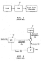
- FIG. 1 the SVM 10 is a piecewise linear engine model representation.
- the SVM must be representative of the engine dynamics at altitude as well as at sea level static conditions. This requirement is fulfilled by providing engine numerics at sea level as well as at several discrete altitude-Mach number combinations and by modeling the SVM in terms of corrected or referred parameters. Since SVM's are fairly simple models, they do not impose a computational burden and are favorably suited for real-time applications. This feature makes the SVM ideal for the applications mentioned above.
- the SVM engine model typically consists of an n state piecewise linear structure which is valid across a flight envelope ranging from sea level static to approximately 50,000 feet altitude.
- the model states typically include the engine's shaft rotor speeds as well as several metal temperatures with the hot section modules (turbines and combustor) and high pressure compressor.
- the states, along with the output engine parameters being modeled (as well as their associated numerics) are expressed in terms of (standard day) corrected parameters and as such the model remains valid at non-International Standard Atmosphere (ISA) conditions. Appropriate correction factors are applied to inputs to correct parameters upon entering the model and the same correction applied in reverse to UN-correct the outputs. This process is depicted in FIG. 1 .
- the SVM consists of a linear state variable model described by a set of first order differential equations.
- A, B, C, and D are matrices of partial derivates and ⁇ x and ⁇ u are deltas from steady state conditions of the engine states and inputs, respectively.
- the steady state parameter values and partial derivatives are determined through small signal perturbation of a nonlinear model of the engine, for example a state of the art performance program. These equations are directly modeled within the SVM 10.
- the steady state baselines and partial derivatives are scheduled as a function of engine power (typically N2) and flight condition.
- N2 engine power
- the flight envelope for which the engine numerics within the SVM 10 are represented is whatever is typical for the engine in question.
- the engine model structure described above generally provides an adequate model for steady state and slow transient operation.
- the SVM admits a much greater error.
- this level of error is generally unacceptable.
- an adaptable SVM such as that shown in FIG. 2 is essential.
- One adaptable SVM technique which has been used with success is to provide a Kalman filter (KF) observer 12 which acts upon the residuals (r) formed by the output P of the SVM 10 and the actual observed measurements P from the engine 14 to provide a set of tuners ( x ⁇ ) which adapt the SVM 10 to match the actual observations (hence driving the residuals to zero on the average).
- the tuners ( x ⁇ ) consist of a set of engine module performance parameters such as efficiencies and flow parameters which allow the engine states and output parameters to be adjusted to allow a more faithful match to the actual engine.
- a drawback of the adaptable SVM model shown in FIG. 2 is that the steady state level of the tuners may take on an unreasonable level in order to adapt a particularly deficient SVM model to a particular engine or engine type during development.
- a system for developing an engine model broadly comprises a module for generating a state variable model of an engine, which module receives a plurality of inputs to an engine representative of a particular flight condition and generates a set of estimated engine parameters representative of the model.
- the system further comprises means for comparing the set of estimated engine parameters to a set of measured engine parameters for generating a set of residuals and an artificial neural network module.
- the artificial neural network module receives the set of residuals and the engine inputs and generates a set of estimated residuals for the particular flight condition.
- a method for developing an engine model broadly comprises providing a module for generating a state variable engine model, inputting a set of engine inputs representative of a particular flight condition into said state variable engine model module and generating a set of estimated engine parameters, comparing the set of estimated engine parameters to measured engine parameters and generating a set of residuals, providing an artificial neural network module, and training the artificial neural network module using the engine inputs and the residuals.
- the method further comprises using the artificial neural network after training has been completed to implement a system for using an engine model.
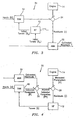
- FIG. 3 illustrates a system 20 during a training phase of an improved adaptable SVM model generator.
- the system 20 includes a module 10 for generating a state variable model of the engine 14.
- the module 10 is implemented by a pre-programmed computer.
- the model generated by the module 10 may be generated using any suitable n state piecewise linear structure known in the art.
- a number of engine parameters are inputted into the module 10.
- the inputs (u) represent a particular flight condition for the engine.
- the inputs (u) may vary from engine to engine model, but typically will take the form of parameters such as fuel flow, variable geometry position such as variable stator vane position, stability bleed commands, various accessory bleeds, horsepower extraction, and other parameters necessary to drive the models.
- Environmental factors such as ambient temperature, pressure, Mach number, altitude, and throttle position may also be inputted.
- the system 20 further has an artificial neural network 22 implemented by the pre-programmed computer.
- the artificial neural network 22 is to be trained for a specified fixed initial engine state to learn the difference between the model generated by the module 10 and the real engine 14 under consideration.
- the artificial neural network 22 may have any desired architecture. For example, it may have an input layer, an output layer, and a number of hidden layers. Each of the layers may have a plurality of nodes which may connected in any desired manner.
- the neural network 22 receives the same inputs as the state variable model module 10. Depending on the configuration of the neural network 22, additional inputs may be used to perform a sort of regime classification to make the modeling easier.
- the system 20 further has a Kalman filter observer module 12 for supplying a set of initial tuners ( x ⁇ 0 ) to the module 10 to update the state variable engine model.
- the Kalman filter observer module 12 may comprise any suitable Kalman filter observer construction known in the art and may also be implemented by the pre-programmed computer.
- the initial tuners x ⁇ 0 are a user specified vector of initial tuner values.
- the tuners within the model typically take the form of changes in engine component efficiencies, flow capacities, and turbine nozzle areas.
- the initial value could be a vector of zeros for instance which would imply that the assumed state of the engine is nominal, i.e. zero delta form reference with the reference being a reference engine, such as the average production engine. Alternatively, the vector could be non-zero if there was some information known or assumed regarding the particular engine 14 under consideration. As noted in FIG. 3 , the residuals supplied to the Kalman filter observer module 12 are initially zero.
- the system 20 further has a comparator 24.
- the comparator 24 receives the output of the state variable engine model module 10 and the measured parameters P from the engine 14 and generates a set of residuals (r) which are supplied to the neural network 22.
- the neural network 22 is programmed to generate a plurality of estimated residuals r ⁇ .
- the estimated residuals (r ⁇ ) are compared to the actual residuals (r) to produce an error term.
- the training is continued until the error is sufficiently small or is not changing with additional training.
- the error is a measure of how well one has mapped the residual difference between the real engine 14 and the state variable engine model module 10 output with a fixed initial tuner vector.
- FIG 4 illustrates the system 20 in an implementation mode.
- the system 20 constitutes a hybrid model utilizing a physics based component (the module 10) and an empirical component (the neural network 22).
- the state variable engine model module 10 is supplied with the engine inputs (u), as well as a set of tuners X from the Kalman filter observer module 12, and is used to generate a plurality of estimated parameters P ⁇ .
- the neural network 22 receives the same inputs supplied to the module 10 and is used to generate a set of estimated residuals r ⁇ .
- the estimated residuals r ⁇ and the estimated parameters P ⁇ are inputted to a comparator 26.
- the comparator 26 generates a set of adjusted estimated parameters P * .
- the adjusted estimated parameters P * and the measured engine parameters P are fed to a second comparator 28.
- the second comparator 28 uses these inputs to generate a set of residuals r which are supplied to the Kalman filter observer module 12.
- the output of the system 20 in the implementation mode is internal to the system.
- the artificial neural network empirical element in the system 20 accounts for the initial difference between the actual engine and the model with assumed initial tuner vector. This configuration has the advantage of relieving the tuners from absorbing the model error and allows the tuners to track component performance degradation of the engine 14 over time in terms of efficiencies and the like.
- the system 20 shown in FIGS. 3 and 4 more accurately reflects the real engine.
- the system 20 may be used in control law design and development such as control loop compensation determination, real time engine for dry bench test, real time engine for wet bench test, and aid in fuel metering unit (FMU) development/test.
- the system 20 may also be used in real-time engine parameter synthesis such as FADEC fault accommodation logic and virtual sensors.
- the system 20 may also be used in engine performance diagnostics for long term deterioration trending and/or event detection.
- the comparators 24, 26, and 28 may also be implemented using a pre-programmed computer.
Landscapes
- Engineering & Computer Science (AREA)
- Artificial Intelligence (AREA)
- Evolutionary Computation (AREA)
- Physics & Mathematics (AREA)
- General Physics & Mathematics (AREA)
- Automation & Control Theory (AREA)
- Health & Medical Sciences (AREA)
- Computer Vision & Pattern Recognition (AREA)
- Medical Informatics (AREA)
- Software Systems (AREA)
- Feedback Control In General (AREA)
- Combined Controls Of Internal Combustion Engines (AREA)
Abstract
Description
- The present invention relates to a system and a method for developing an engine model.
- Gas turbine state variable models (SVM) have long been employed to support the design, development, and testing of modern full authority digital engine controls (FADECS) as well as applications requiring real-time deployment of an engine model. Referring now to
FIG. 1 , theSVM 10 is a piecewise linear engine model representation. For control law applications, this allows a simple system identification to be performed in terms of transfer functions which in turn are used to determine the control gains and compensation for the various control loops that will govern the engine operation. This is performed across the flight envelope. Thus, the SVM must be representative of the engine dynamics at altitude as well as at sea level static conditions. This requirement is fulfilled by providing engine numerics at sea level as well as at several discrete altitude-Mach number combinations and by modeling the SVM in terms of corrected or referred parameters. Since SVM's are fairly simple models, they do not impose a computational burden and are favorably suited for real-time applications. This feature makes the SVM ideal for the applications mentioned above. - The SVM engine model typically consists of an n state piecewise linear structure which is valid across a flight envelope ranging from sea level static to approximately 50,000 feet altitude. The model states typically include the engine's shaft rotor speeds as well as several metal temperatures with the hot section modules (turbines and combustor) and high pressure compressor. The states, along with the output engine parameters being modeled (as well as their associated numerics) are expressed in terms of (standard day) corrected parameters and as such the model remains valid at non-International Standard Atmosphere (ISA) conditions. Appropriate correction factors are applied to inputs to correct parameters upon entering the model and the same correction applied in reverse to UN-correct the outputs. This process is depicted in
FIG. 1 . - The SVM consists of a linear state variable model described by a set of first order differential equations. In general, the outputs (y) of the gas turbine engine may be considered to be a nonlinear function of its inputs (u) and states (x), i.e.

- This implies that:


where A, B, C, and D are matrices of partial derivates and Δx and Δu are deltas from steady state conditions of the engine states and inputs, respectively. The steady state parameter values and partial derivatives are determined through small signal perturbation of a nonlinear model of the engine, for example a state of the art performance program. These equations are directly modeled within theSVM 10. The steady state baselines and partial derivatives are scheduled as a function of engine power (typically N2) and flight condition. For the latter, Reynold's Index may be used which combines the effects of altitude and Mach number. Reynold's Index is computed as Rel = σ/θ1.25. The flight envelope for which the engine numerics within theSVM 10 are represented is whatever is typical for the engine in question. - The engine model structure described above generally provides an adequate model for steady state and slow transient operation. For rapid transients or operation across a wide power range (e.g. idle to takeoff), the SVM admits a much greater error. For the purpose of parameter synthesis during these types of transients, this level of error is generally unacceptable. To mitigate the transients effects, an adaptable SVM such as that shown in
FIG. 2 is essential. - One adaptable SVM technique which has been used with success is to provide a Kalman filter (KF)
observer 12 which acts upon the residuals (r) formed by the output P of theSVM 10 and the actual observed measurements P from theengine 14 to provide a set of tuners (x̂) which adapt theSVM 10 to match the actual observations (hence driving the residuals to zero on the average). The tuners (x̂) consist of a set of engine module performance parameters such as efficiencies and flow parameters which allow the engine states and output parameters to be adjusted to allow a more faithful match to the actual engine. - A drawback of the adaptable SVM model shown in
FIG. 2 is that the steady state level of the tuners may take on an unreasonable level in order to adapt a particularly deficient SVM model to a particular engine or engine type during development. - What is needed is a system architecture and a method to initialize the SVM to reflect a given initial state (in terms of the efficiencies and flow parameters) so that at installation the revised adaptable SVM matches the real engine in terms of generating average zero residuals as well as admitting the specified initial engine state.
- Accordingly, it is an object of the present invention to provide a system architecture and a method for initializing a SVM to reflect a given initial state so that an adaptable SVM matches the real engine in terms of generating average zero residuals.
- The foregoing object is attained by the system and method of the present invention.
- In accordance with the present invention, a system for developing an engine model is provided. The system broadly comprises a module for generating a state variable model of an engine, which module receives a plurality of inputs to an engine representative of a particular flight condition and generates a set of estimated engine parameters representative of the model. The system further comprises means for comparing the set of estimated engine parameters to a set of measured engine parameters for generating a set of residuals and an artificial neural network module. During training, the artificial neural network module receives the set of residuals and the engine inputs and generates a set of estimated residuals for the particular flight condition.
- A method for developing an engine model broadly comprises providing a module for generating a state variable engine model, inputting a set of engine inputs representative of a particular flight condition into said state variable engine model module and generating a set of estimated engine parameters, comparing the set of estimated engine parameters to measured engine parameters and generating a set of residuals, providing an artificial neural network module, and training the artificial neural network module using the engine inputs and the residuals. The method further comprises using the artificial neural network after training has been completed to implement a system for using an engine model.
- Other details of the hybrid gas turbine engine state variable model of the present invention, as well as other advantages attendant thereto, are set forth in the following detailed description and the accompanying drawings wherein like reference numerals depict like elements.
-
-
FIG. 1 is a schematic representation of a prior art general state variable model structure; -
FIG. 2 is a schematic representation of a prior art adaptable state variable model structure; -
FIG. 3 is a schematic representation of a system architecture for a training implementation of a state variable model in accordance with the present invention; and -
FIG. 4 is a schematic representation of a system architecture for an implementation version of an extended adaptable state variable model in accordance with the present invention. - Referring now to the drawings,
FIG. 3 illustrates asystem 20 during a training phase of an improved adaptable SVM model generator. Thesystem 20 includes amodule 10 for generating a state variable model of theengine 14. Themodule 10 is implemented by a pre-programmed computer. The model generated by themodule 10 may be generated using any suitable n state piecewise linear structure known in the art. As before, a number of engine parameters are inputted into themodule 10. The inputs (u) represent a particular flight condition for the engine. The inputs (u) may vary from engine to engine model, but typically will take the form of parameters such as fuel flow, variable geometry position such as variable stator vane position, stability bleed commands, various accessory bleeds, horsepower extraction, and other parameters necessary to drive the models. Environmental factors such as ambient temperature, pressure, Mach number, altitude, and throttle position may also be inputted. - The
system 20 further has an artificialneural network 22 implemented by the pre-programmed computer. The artificialneural network 22 is to be trained for a specified fixed initial engine state to learn the difference between the model generated by themodule 10 and thereal engine 14 under consideration. The artificialneural network 22 may have any desired architecture. For example, it may have an input layer, an output layer, and a number of hidden layers. Each of the layers may have a plurality of nodes which may connected in any desired manner. Theneural network 22 receives the same inputs as the statevariable model module 10. Depending on the configuration of theneural network 22, additional inputs may be used to perform a sort of regime classification to make the modeling easier. - The
system 20 further has a Kalmanfilter observer module 12 for supplying a set of initial tuners (x̂ 0) to themodule 10 to update the state variable engine model. The Kalmanfilter observer module 12 may comprise any suitable Kalman filter observer construction known in the art and may also be implemented by the pre-programmed computer. The initial tuners x̂ 0 are a user specified vector of initial tuner values. The tuners within the model typically take the form of changes in engine component efficiencies, flow capacities, and turbine nozzle areas. The initial value could be a vector of zeros for instance which would imply that the assumed state of the engine is nominal, i.e. zero delta form reference with the reference being a reference engine, such as the average production engine. Alternatively, the vector could be non-zero if there was some information known or assumed regarding theparticular engine 14 under consideration. As noted inFIG. 3 , the residuals supplied to the Kalmanfilter observer module 12 are initially zero. - The
system 20 further has acomparator 24. Thecomparator 24 receives the output of the state variableengine model module 10 and the measured parameters P from theengine 14 and generates a set of residuals (r) which are supplied to theneural network 22. Theneural network 22 is programmed to generate a plurality of estimated residuals r̂. - During the training mode, the estimated residuals (r̂) are compared to the actual residuals (r) to produce an error term. The training is continued until the error is sufficiently small or is not changing with additional training. The error is a measure of how well one has mapped the residual difference between the
real engine 14 and the state variableengine model module 10 output with a fixed initial tuner vector. After the artificialneural network 22 has been trained to statistically represent the residuals produced between the existing state variable engine model and the real engine under a wide range of steady state operating conditions, an extended adaptable state variable engine model can be implemented as shown inFIG. 4 . -
FIG 4 illustrates thesystem 20 in an implementation mode. As can be seen from this figure, thesystem 20 constitutes a hybrid model utilizing a physics based component (the module 10) and an empirical component (the neural network 22). In this implementation mode, the state variableengine model module 10 is supplied with the engine inputs (u), as well as a set of tuners X from the Kalmanfilter observer module 12, and is used to generate a plurality of estimated parameters P̂. Theneural network 22 receives the same inputs supplied to themodule 10 and is used to generate a set of estimated residuals r̂. The estimated residuals r̂ and the estimated parameters P̂ are inputted to acomparator 26. Thecomparator 26 generates a set of adjusted estimated parameters P*. The adjusted estimated parameters P* and the measured engine parameters P are fed to asecond comparator 28. Thesecond comparator 28 uses these inputs to generate a set of residuals r which are supplied to the Kalmanfilter observer module 12. - As can be seen from
FIG. 4 , the output of thesystem 20 in the implementation mode is internal to the system. The artificial neural network empirical element in thesystem 20 accounts for the initial difference between the actual engine and the model with assumed initial tuner vector. This configuration has the advantage of relieving the tuners from absorbing the model error and allows the tuners to track component performance degradation of theengine 14 over time in terms of efficiencies and the like. Thesystem 20 shown inFIGS. 3 and 4 more accurately reflects the real engine. - The
system 20 may be used in control law design and development such as control loop compensation determination, real time engine for dry bench test, real time engine for wet bench test, and aid in fuel metering unit (FMU) development/test. Thesystem 20 may also be used in real-time engine parameter synthesis such as FADEC fault accommodation logic and virtual sensors. Thesystem 20 may also be used in engine performance diagnostics for long term deterioration trending and/or event detection. - The
comparators - It is apparent that there has been described above a hybrid gas turbine engine state variable model which fully satisfies the objects, means, and advantages set forth hereinbefore. While the present invention has been described in the context of specific embodiments thereof, other alternatives, modifications, and variations will become apparent to those skilled in the art having read the foregoing description. Accordingly, it is intended to embrace those alternatives, modifications, and variations as fall within the broad scope of the appended claims.
Claims (5)
- A system (20) for providing an adaptable engine model comprising:a module (10) for generating a state variable model of an engine, said module (10) receiving a plurality of inputs (u) to an engine representative of a particular flight condition and generating a set of estimated engine parameters (P̂) representative of said engine model;a neural network model (22) for receiving said plurality of engine inputs (u) and generating a set of estimated residuals (r̂);a first comparator (26) for comparing said set of estimated residuals (r̂) with said set of estimated engine parameters (P̂) and generating a set of adjusted estimated parameters (P̂*);a second comparator (28) for comparing said set of adjusted engine parameters (P̂*) with a set of measured engine parameters (P) to generate a revised set of residuals (r); anda Kalman filter module (12) for receiving said revised set of residuals (r) and converting said revised set of residuals to a revised set of tuning vectors (x̂).
- A system according to claim 1, wherein said state variable model module (10) is configured to receive said revised set of tuning vectors so that said state variable model (10) module generates a revised set of estimated parameters (P̂).
- A method for providing an adaptable engine model comprising:(a) providing a module (10) for generating a state variable model of an engine, said module (10) receiving a plurality of inputs (u) to an engine representative of a particular flight condition and generating a set of estimated engine parameters (P̂) representative of said engine model;(b) providing a neural network module (22) for receiving said plurality of engine inputs (u) and generating a set of estimated residuals (r̂);(c) providing a first comparator (26) for comparing said set of estimated residuals (r̂) with said set of estimated engine parameters (P̂) and generating a set of adjusted estimated parameters (P̂*);(d) providing a second comparator (28) for comparing said set of adjusted engine parameters (P̂*) with a set of measured engine parameters (p) to generate a revised set of residuals (r); and(e) providing a Kalman filter module (12) for receiving said revised set of residuals (r) and converting said revised set of residuals to a revised set of tuning vectors (x̂).
- A method according to claim 3, further comprising:(f) supplying said revised set of tuning vectors (x̂) to said state variable engine model module (10) and generating a new set of estimated parameters.
- A method according to claim 4, further comprising repeating steps (c), (d), and (e) using said new set of estimated parameters.
Applications Claiming Priority (2)
| Application Number | Priority Date | Filing Date | Title |
|---|---|---|---|
| US10/132,108 US7216071B2 (en) | 2002-04-23 | 2002-04-23 | Hybrid gas turbine engine state variable model |
| EP03252453.0A EP1357487B1 (en) | 2002-04-23 | 2003-04-17 | Method and system for developing a hybrid gas turbine engine state variable model |
Related Parent Applications (3)
| Application Number | Title | Priority Date | Filing Date |
|---|---|---|---|
| EP03252453.0 Division | 2003-04-17 | ||
| EP03252453.0A Division-Into EP1357487B1 (en) | 2002-04-23 | 2003-04-17 | Method and system for developing a hybrid gas turbine engine state variable model |
| EP03252453.0A Division EP1357487B1 (en) | 2002-04-23 | 2003-04-17 | Method and system for developing a hybrid gas turbine engine state variable model |
Publications (2)
| Publication Number | Publication Date |
|---|---|
| EP2336919A1 true EP2336919A1 (en) | 2011-06-22 |
| EP2336919B1 EP2336919B1 (en) | 2017-07-26 |
Family
ID=28790997
Family Applications (2)
| Application Number | Title | Priority Date | Filing Date |
|---|---|---|---|
| EP10011544.3A Expired - Lifetime EP2336919B1 (en) | 2002-04-23 | 2003-04-17 | Method and system for developing a hybrid gas turbine engine state variable model |
| EP03252453.0A Expired - Lifetime EP1357487B1 (en) | 2002-04-23 | 2003-04-17 | Method and system for developing a hybrid gas turbine engine state variable model |
Family Applications After (1)
| Application Number | Title | Priority Date | Filing Date |
|---|---|---|---|
| EP03252453.0A Expired - Lifetime EP1357487B1 (en) | 2002-04-23 | 2003-04-17 | Method and system for developing a hybrid gas turbine engine state variable model |
Country Status (3)
| Country | Link |
|---|---|
| US (1) | US7216071B2 (en) |
| EP (2) | EP2336919B1 (en) |
| JP (1) | JP2004028087A (en) |
Cited By (1)
| Publication number | Priority date | Publication date | Assignee | Title |
|---|---|---|---|---|
| RU2654310C2 (en) * | 2014-04-03 | 2018-05-17 | Сафран Эркрафт Энджинз | Method and device for the rocket engine parameter monitoring |
Families Citing this family (40)
| Publication number | Priority date | Publication date | Assignee | Title |
|---|---|---|---|---|
| US6895375B2 (en) * | 2001-10-04 | 2005-05-17 | At&T Corp. | System for bandwidth extension of Narrow-band speech |
| US7277838B2 (en) * | 2004-08-26 | 2007-10-02 | United Technologies Corporation | Bootstrap data methodology for sequential hybrid model building |
| US7415328B2 (en) * | 2004-10-04 | 2008-08-19 | United Technologies Corporation | Hybrid model based fault detection and isolation system |
| FR2876152B1 (en) * | 2004-10-06 | 2006-12-15 | Renault Sas | IMPROVED METHOD AND SYSTEM FOR ESTIMATING EXHAUST GAS TEMPERATURE AND INTERNAL COMBUSTION ENGINE EQUIPPED WITH SUCH A SYSTEM |
| US7742904B2 (en) * | 2005-09-27 | 2010-06-22 | General Electric Company | Method and system for gas turbine engine simulation using adaptive Kalman filter |
| US7505844B2 (en) | 2005-11-18 | 2009-03-17 | General Electric Company | Model-based iterative estimation of gas turbine engine component qualities |
| US7451122B2 (en) * | 2006-03-29 | 2008-11-11 | Honeywell International Inc. | Empirical design of experiments using neural network models |
| US7472100B2 (en) * | 2006-09-29 | 2008-12-30 | United Technologies Corporation | Empirical tuning of an on board real-time gas turbine engine model |
| DE102007001024B4 (en) * | 2007-01-02 | 2008-10-02 | Siemens Ag | Method for computer-aided control and / or control of a technical system, in particular of a gas turbine |
| US7441448B2 (en) * | 2007-01-24 | 2008-10-28 | United Technologies Corporation | Process for adapting measurement suite configuration for gas turbine performance diagnostics |
| US7853441B2 (en) * | 2007-08-22 | 2010-12-14 | United Technologies Corp. | Systems and methods involving engine models |
| US20090112519A1 (en) * | 2007-10-31 | 2009-04-30 | United Technologies Corporation | Foreign object/domestic object damage assessment |
| US9074531B2 (en) | 2008-03-05 | 2015-07-07 | United Technologies Corporation | Variable area fan nozzle fan flutter management system |
| US20090226303A1 (en) * | 2008-03-05 | 2009-09-10 | Grabowski Zbigniew M | Variable area fan nozzle fan flutter management system |
| US7788209B2 (en) * | 2008-05-05 | 2010-08-31 | United Technologies Corporation | Hybrid fault reasoning and guided troubleshooting system that uses case-based reasoning and model-based reasoning |
| US7881880B2 (en) * | 2009-04-01 | 2011-02-01 | United Technologies Corporation | Actuator performance monitoring system |
| US8306791B2 (en) * | 2009-12-21 | 2012-11-06 | United Technologies Corporation | Method and system for modeling the performance of a gas turbine engine |
| US8862433B2 (en) | 2010-05-18 | 2014-10-14 | United Technologies Corporation | Partitioning of turbomachine faults |
| US9342060B2 (en) | 2010-09-14 | 2016-05-17 | United Technologies Corporation | Adaptive control for a gas turbine engine |
| US8682454B2 (en) | 2011-02-28 | 2014-03-25 | United Technologies Corporation | Method and system for controlling a multivariable system with limits |
| US8899488B2 (en) | 2011-05-31 | 2014-12-02 | United Technologies Corporation | RFID tag system |
| WO2013123385A1 (en) | 2012-02-15 | 2013-08-22 | Rolls-Royce Corporation | Gas turbine engine performance seeking control |
| US8720258B2 (en) | 2012-09-28 | 2014-05-13 | United Technologies Corporation | Model based engine inlet condition estimation |
| US9540944B2 (en) | 2012-09-28 | 2017-01-10 | United Technologies Corporation | Real time model based compressor control |
| US20140222310A1 (en) * | 2012-10-09 | 2014-08-07 | United Technologies Corporation | Engine monitor for a multi-engine system |
| EP3158408A4 (en) | 2014-06-20 | 2017-05-10 | Atigeo Corp. | Cooperative distributed control of target systems |
| US10240544B2 (en) | 2016-10-27 | 2019-03-26 | Rolls-Royce Corporation | Adaptive controller using unmeasured operating parameter |
| US10309330B2 (en) | 2016-10-27 | 2019-06-04 | Rolls-Royce Corporation | Model reference adaptive controller |
| US10012566B2 (en) | 2016-11-14 | 2018-07-03 | United Technologies Corporation | Parametric trending architecture concept and design |
| CN108196450A (en) * | 2017-12-29 | 2018-06-22 | 吉林大学 | Engine idling control system design method based on support vector machines |
| US10961921B2 (en) | 2018-09-19 | 2021-03-30 | Pratt & Whitney Canada Corp. | Model-based control system and method for a turboprop engine |
| US10964130B1 (en) | 2018-10-18 | 2021-03-30 | Northrop Grumman Systems Corporation | Fleet level prognostics for improved maintenance of vehicles |
| US11300069B2 (en) | 2018-11-28 | 2022-04-12 | Honeywell International Inc. | Self-generating engine-specific health monitoring model from generic model base |
| US12180892B2 (en) * | 2019-02-01 | 2024-12-31 | Rtx Corporation | Machine learned aero-thermodynamic engine inlet condition synthesis |
| EP3705953B1 (en) | 2019-03-06 | 2023-08-30 | Robert Bosch GmbH | Control of a physical system based on inferred state |
| WO2021173356A1 (en) * | 2020-02-26 | 2021-09-02 | Northrop Grumman Systems Corporation | Prognostics for improved maintenance of vehicles |
| CN113158564B (en) * | 2021-04-19 | 2024-03-29 | 南京航空航天大学 | Method for establishing state variable model of aero-engine based on data driving |
| US11681811B1 (en) | 2021-06-25 | 2023-06-20 | Northrop Grumman Systems Corporation | Cybersecurity for configuration and software updates of vehicle hardware and software based on fleet level information |
| US11409866B1 (en) | 2021-06-25 | 2022-08-09 | Northrop Grumman Systems Corporation | Adaptive cybersecurity for vehicles |
| US12577917B2 (en) | 2024-07-08 | 2026-03-17 | General Electric Company | Method of operating a gas turbine engine |
Citations (2)
| Publication number | Priority date | Publication date | Assignee | Title |
|---|---|---|---|---|
| GB1597129A (en) * | 1976-12-20 | 1981-09-03 | Gen Electric | Gas turbine engine control system |
| FR2772427A1 (en) * | 1997-12-12 | 1999-06-18 | Renault | NEURON NETWORK ENGINE CONTROL SYSTEM |
Family Cites Families (16)
| Publication number | Priority date | Publication date | Assignee | Title |
|---|---|---|---|---|
| US4411595A (en) * | 1979-09-19 | 1983-10-25 | General Electric Company | Control system for gas turbine engine |
| JP3703117B2 (en) * | 1996-07-10 | 2005-10-05 | ヤマハ発動機株式会社 | Model-based control method and apparatus |
| GB2321720A (en) | 1997-02-04 | 1998-08-05 | Secr Defence | Modelling a system with more parameters than sensors |
| JP3987199B2 (en) * | 1998-03-31 | 2007-10-03 | マツダ株式会社 | Simulation device, simulation method, and storage medium |
| US6415272B1 (en) * | 1998-10-22 | 2002-07-02 | Yamaha Hatsudoki Kabushiki Kaisha | System for intelligent control based on soft computing |
| US6216083B1 (en) * | 1998-10-22 | 2001-04-10 | Yamaha Motor Co., Ltd. | System for intelligent control of an engine based on soft computing |
| US6301572B1 (en) * | 1998-12-02 | 2001-10-09 | Lockheed Martin Corporation | Neural network based analysis system for vibration analysis and condition monitoring |
| US6985781B2 (en) * | 1999-01-12 | 2006-01-10 | Pavilion Technologies, Inc. | Residual activation neural network |
| CA2266282A1 (en) * | 1999-03-19 | 2000-09-19 | Leandre Nneme Nneme | A self-tuning kalman filter |
| US7020595B1 (en) * | 1999-11-26 | 2006-03-28 | General Electric Company | Methods and apparatus for model based diagnostics |
| JP4743944B2 (en) * | 2000-08-25 | 2011-08-10 | 鎮男 角田 | Simulation model creation method and system and storage medium |
| JP3758134B2 (en) * | 2000-10-23 | 2006-03-22 | 株式会社デンソー | Control device for internal combustion engine |
| US7058556B2 (en) * | 2001-09-26 | 2006-06-06 | Goodrich Pump & Engine Control Systems, Inc. | Adaptive aero-thermodynamic engine model |
| US6909960B2 (en) * | 2002-10-31 | 2005-06-21 | United Technologies Corporation | Method for performing gas turbine performance diagnostics |
| US6823675B2 (en) * | 2002-11-13 | 2004-11-30 | General Electric Company | Adaptive model-based control systems and methods for controlling a gas turbine |
| US7321809B2 (en) * | 2003-12-30 | 2008-01-22 | The Boeing Company | Methods and systems for analyzing engine unbalance conditions |
-
2002
- 2002-04-23 US US10/132,108 patent/US7216071B2/en not_active Expired - Lifetime
-
2003
- 2003-04-17 EP EP10011544.3A patent/EP2336919B1/en not_active Expired - Lifetime
- 2003-04-17 EP EP03252453.0A patent/EP1357487B1/en not_active Expired - Lifetime
- 2003-04-23 JP JP2003117931A patent/JP2004028087A/en not_active Ceased
Patent Citations (2)
| Publication number | Priority date | Publication date | Assignee | Title |
|---|---|---|---|---|
| GB1597129A (en) * | 1976-12-20 | 1981-09-03 | Gen Electric | Gas turbine engine control system |
| FR2772427A1 (en) * | 1997-12-12 | 1999-06-18 | Renault | NEURON NETWORK ENGINE CONTROL SYSTEM |
Non-Patent Citations (4)
| Title |
|---|
| HORTON M P: "Real-time identification of missile aerodynamics using a linearised Kalman filter aided by an artificial neural network", IEE PROCEEDINGS D. CONTROL THEORY & APPLICATIONS, INSTITUTION OF ELECTRICAL ENGINEERS. STEVENAGE, GB, vol. 144, no. 4, 29 July 1997 (1997-07-29), pages 299 - 308, XP006008537, ISSN: 0143-7054 * |
| PATEL V C ET AL: "Gas turbine engine condition monitoring using statistical and neural network methods", MODELING AND SIGNAL PROCESSING FOR FAULT DIAGNOSIS (DIGEST NO: 1996/260) IEE COLLOQIUM, 18 September 1996 (1996-09-18), pages 1 - 1, XP006509360 * |
| PUSKORIUS G V ET AL: "NEUROCONTROL OF NONLINEAR DYNAMICAL SYSTEMS WITH KALMAN FILTER TRAINED RECURRENT NETWORKS", IEEE TRANSACTIONS ON NEURAL NETWORKS, IEEE SERVICE CENTER, PISCATAWAY, NJ, US, vol. 5, no. 2, 1 March 1994 (1994-03-01), pages 279 - 297, XP000441810, ISSN: 1045-9227 * |
| VOLPONI A J ET AL: "THE USE OF KALMAN FILTER AND NEURAL NETWORK METHDOLOGIES IN GAS TURBINE PERFORMANCE DIAGNOSTICS: A COMPARATIVE STUDY", JOURNAL OF ENGINEERING FOR GAS TURBINES AND POWER, ASME, NEW YORK, NY, US, vol. 125, no. 4, October 2003 (2003-10-01), pages 917 - 924, XP009066721, ISSN: 0742-4795 * |
Cited By (1)
| Publication number | Priority date | Publication date | Assignee | Title |
|---|---|---|---|---|
| RU2654310C2 (en) * | 2014-04-03 | 2018-05-17 | Сафран Эркрафт Энджинз | Method and device for the rocket engine parameter monitoring |
Also Published As
| Publication number | Publication date |
|---|---|
| JP2004028087A (en) | 2004-01-29 |
| US20030200069A1 (en) | 2003-10-23 |
| EP1357487A2 (en) | 2003-10-29 |
| US7216071B2 (en) | 2007-05-08 |
| EP1357487B1 (en) | 2017-03-29 |
| EP1357487A3 (en) | 2007-05-09 |
| EP2336919B1 (en) | 2017-07-26 |
Similar Documents
| Publication | Publication Date | Title |
|---|---|---|
| EP2336919B1 (en) | Method and system for developing a hybrid gas turbine engine state variable model | |
| US20250320832A1 (en) | Machine learned aero-thermodynamic engine inlet condition synthesis | |
| US7020595B1 (en) | Methods and apparatus for model based diagnostics | |
| Kobayashi et al. | Application of a constant gain extended Kalman filter for in-flight estimation of aircraft engine performance parameters | |
| US4275557A (en) | Method and apparatus for controlling thrust in a gas turbine engine | |
| US7058556B2 (en) | Adaptive aero-thermodynamic engine model | |
| US5233512A (en) | Method and apparatus for actuator fault detection | |
| US20180119628A1 (en) | Adaptive controller | |
| IL140101A (en) | Methods and system for estimating engine faults | |
| Connolly et al. | Advanced control considerations for turbofan engine design | |
| Kobayashi et al. | Hybrid Kalman filter approach for aircraft engine in-flight diagnostics: Sensor fault detection case | |
| US11435707B2 (en) | Hybrid system for controlling an aircraft and method for controlling the same | |
| US12140085B2 (en) | System and method for detecting and accommodating loss of torque on gas turbine engines | |
| EP1538319B1 (en) | Apparatus for model predictive control of aircraft gas turbine engines | |
| Connolly et al. | Model-based control of a nonlinear aircraft engine simulation using an optimal tuner Kalman filter approach | |
| Adibhatla et al. | Model-based intelligent digital engine control (MoBIDEC) | |
| Főző et al. | Description of an intelligent small turbo-compressor engine with variable exhaust nozzle | |
| Beneda | Modular electronic turbojet control system based on TPR | |
| Alag et al. | A proposed Kalman filter algorithm for estimation of unmeasured output variables for an F100 turbofan engine | |
| Sanusi et al. | Reinforcement learning for condition-based control of gas turbine engines | |
| Turevskiy et al. | A model-based controller for commercial aero gas turbines | |
| Litt et al. | Evaluation of an outer loop retrofit architecture for intelligent turbofan engine thrust control | |
| CN117852176A (en) | A hybrid modeling method for turboshaft engines combined with data-driven modules | |
| RU2412366C1 (en) | System of automatic control of gas-turbine engine | |
| EP4442979A1 (en) | Systems and methods for adjusting a modulation characteristic of a bleed-off valve of a gas turbine engine |
Legal Events
| Date | Code | Title | Description |
|---|---|---|---|
| PUAI | Public reference made under article 153(3) epc to a published international application that has entered the european phase |
Free format text: ORIGINAL CODE: 0009012 |
|
| AC | Divisional application: reference to earlier application |
Ref document number: 1357487 Country of ref document: EP Kind code of ref document: P |
|
| AK | Designated contracting states |
Kind code of ref document: A1 Designated state(s): DE FR GB |
|
| 17P | Request for examination filed |
Effective date: 20111221 |
|
| 17Q | First examination report despatched |
Effective date: 20150817 |
|
| RAP1 | Party data changed (applicant data changed or rights of an application transferred) |
Owner name: UNITED TECHNOLOGIES CORPORATION |
|
| REG | Reference to a national code |
Ref country code: DE Ref legal event code: R079 Ref document number: 60350446 Country of ref document: DE Free format text: PREVIOUS MAIN CLASS: G06F0017500000 Ipc: G05B0017020000 |
|
| GRAP | Despatch of communication of intention to grant a patent |
Free format text: ORIGINAL CODE: EPIDOSNIGR1 |
|
| STAA | Information on the status of an ep patent application or granted ep patent |
Free format text: STATUS: GRANT OF PATENT IS INTENDED |
|
| RIC1 | Information provided on ipc code assigned before grant |
Ipc: G05B 17/02 20060101AFI20170119BHEP Ipc: G05B 13/02 20060101ALI20170119BHEP |
|
| INTG | Intention to grant announced |
Effective date: 20170209 |
|
| GRAS | Grant fee paid |
Free format text: ORIGINAL CODE: EPIDOSNIGR3 |
|
| GRAA | (expected) grant |
Free format text: ORIGINAL CODE: 0009210 |
|
| STAA | Information on the status of an ep patent application or granted ep patent |
Free format text: STATUS: THE PATENT HAS BEEN GRANTED |
|
| AC | Divisional application: reference to earlier application |
Ref document number: 1357487 Country of ref document: EP Kind code of ref document: P |
|
| AK | Designated contracting states |
Kind code of ref document: B1 Designated state(s): DE FR GB |
|
| REG | Reference to a national code |
Ref country code: GB Ref legal event code: FG4D |
|
| REG | Reference to a national code |
Ref country code: DE Ref legal event code: R096 Ref document number: 60350446 Country of ref document: DE |
|
| REG | Reference to a national code |
Ref country code: DE Ref legal event code: R097 Ref document number: 60350446 Country of ref document: DE |
|
| PLBE | No opposition filed within time limit |
Free format text: ORIGINAL CODE: 0009261 |
|
| STAA | Information on the status of an ep patent application or granted ep patent |
Free format text: STATUS: NO OPPOSITION FILED WITHIN TIME LIMIT |
|
| 26N | No opposition filed |
Effective date: 20180430 |
|
| PG25 | Lapsed in a contracting state [announced via postgrant information from national office to epo] |
Ref country code: FR Free format text: LAPSE BECAUSE OF NON-PAYMENT OF DUE FEES Effective date: 20180430 |
|
| PGFP | Annual fee paid to national office [announced via postgrant information from national office to epo] |
Ref country code: GB Payment date: 20200323 Year of fee payment: 18 |
|
| PGFP | Annual fee paid to national office [announced via postgrant information from national office to epo] |
Ref country code: DE Payment date: 20200319 Year of fee payment: 18 |
|
| REG | Reference to a national code |
Ref country code: DE Ref legal event code: R119 Ref document number: 60350446 Country of ref document: DE |
|
| GBPC | Gb: european patent ceased through non-payment of renewal fee |
Effective date: 20210417 |
|
| PG25 | Lapsed in a contracting state [announced via postgrant information from national office to epo] |
Ref country code: DE Free format text: LAPSE BECAUSE OF NON-PAYMENT OF DUE FEES Effective date: 20211103 Ref country code: GB Free format text: LAPSE BECAUSE OF NON-PAYMENT OF DUE FEES Effective date: 20210417 |