EP2336681A1 - Oil equalizing device, compressor unit and oil equalizing method - Google Patents
Oil equalizing device, compressor unit and oil equalizing method Download PDFInfo
- Publication number
- EP2336681A1 EP2336681A1 EP09813971A EP09813971A EP2336681A1 EP 2336681 A1 EP2336681 A1 EP 2336681A1 EP 09813971 A EP09813971 A EP 09813971A EP 09813971 A EP09813971 A EP 09813971A EP 2336681 A1 EP2336681 A1 EP 2336681A1
- Authority
- EP
- European Patent Office
- Prior art keywords
- pipe
- oil
- valve
- compressor
- oil reservoir
- Prior art date
- Legal status (The legal status is an assumption and is not a legal conclusion. Google has not performed a legal analysis and makes no representation as to the accuracy of the status listed.)
- Withdrawn
Links
Images




Classifications
-
- F—MECHANICAL ENGINEERING; LIGHTING; HEATING; WEAPONS; BLASTING
- F25—REFRIGERATION OR COOLING; COMBINED HEATING AND REFRIGERATION SYSTEMS; HEAT PUMP SYSTEMS; MANUFACTURE OR STORAGE OF ICE; LIQUEFACTION SOLIDIFICATION OF GASES
- F25B—REFRIGERATION MACHINES, PLANTS OR SYSTEMS; COMBINED HEATING AND REFRIGERATION SYSTEMS; HEAT PUMP SYSTEMS
- F25B31/00—Compressor arrangements
- F25B31/002—Lubrication
- F25B31/004—Lubrication oil recirculating arrangements
-
- F—MECHANICAL ENGINEERING; LIGHTING; HEATING; WEAPONS; BLASTING
- F25—REFRIGERATION OR COOLING; COMBINED HEATING AND REFRIGERATION SYSTEMS; HEAT PUMP SYSTEMS; MANUFACTURE OR STORAGE OF ICE; LIQUEFACTION SOLIDIFICATION OF GASES
- F25B—REFRIGERATION MACHINES, PLANTS OR SYSTEMS; COMBINED HEATING AND REFRIGERATION SYSTEMS; HEAT PUMP SYSTEMS
- F25B13/00—Compression machines, plants or systems, with reversible cycle
-
- F—MECHANICAL ENGINEERING; LIGHTING; HEATING; WEAPONS; BLASTING
- F25—REFRIGERATION OR COOLING; COMBINED HEATING AND REFRIGERATION SYSTEMS; HEAT PUMP SYSTEMS; MANUFACTURE OR STORAGE OF ICE; LIQUEFACTION SOLIDIFICATION OF GASES
- F25B—REFRIGERATION MACHINES, PLANTS OR SYSTEMS; COMBINED HEATING AND REFRIGERATION SYSTEMS; HEAT PUMP SYSTEMS
- F25B2313/00—Compression machines, plants or systems with reversible cycle not otherwise provided for
- F25B2313/023—Compression machines, plants or systems with reversible cycle not otherwise provided for using multiple indoor units
- F25B2313/0233—Compression machines, plants or systems with reversible cycle not otherwise provided for using multiple indoor units in parallel arrangements
-
- F—MECHANICAL ENGINEERING; LIGHTING; HEATING; WEAPONS; BLASTING
- F25—REFRIGERATION OR COOLING; COMBINED HEATING AND REFRIGERATION SYSTEMS; HEAT PUMP SYSTEMS; MANUFACTURE OR STORAGE OF ICE; LIQUEFACTION SOLIDIFICATION OF GASES
- F25B—REFRIGERATION MACHINES, PLANTS OR SYSTEMS; COMBINED HEATING AND REFRIGERATION SYSTEMS; HEAT PUMP SYSTEMS
- F25B2313/00—Compression machines, plants or systems with reversible cycle not otherwise provided for
- F25B2313/025—Compression machines, plants or systems with reversible cycle not otherwise provided for using multiple outdoor units
- F25B2313/0253—Compression machines, plants or systems with reversible cycle not otherwise provided for using multiple outdoor units in parallel arrangements
-
- F—MECHANICAL ENGINEERING; LIGHTING; HEATING; WEAPONS; BLASTING
- F25—REFRIGERATION OR COOLING; COMBINED HEATING AND REFRIGERATION SYSTEMS; HEAT PUMP SYSTEMS; MANUFACTURE OR STORAGE OF ICE; LIQUEFACTION SOLIDIFICATION OF GASES
- F25B—REFRIGERATION MACHINES, PLANTS OR SYSTEMS; COMBINED HEATING AND REFRIGERATION SYSTEMS; HEAT PUMP SYSTEMS
- F25B2400/00—Component parts or details not otherwise provided for in this subclass
- F25B2400/07—Details of compressors or related parts
- F25B2400/075—Details of compressors or related parts with parallel compressors
-
- Y—GENERAL TAGGING OF NEW TECHNOLOGICAL DEVELOPMENTS; GENERAL TAGGING OF CROSS-SECTIONAL TECHNOLOGIES SPANNING OVER SEVERAL SECTIONS OF THE IPC; TECHNICAL SUBJECTS COVERED BY FORMER USPC CROSS-REFERENCE ART COLLECTIONS [XRACs] AND DIGESTS
- Y10—TECHNICAL SUBJECTS COVERED BY FORMER USPC
- Y10S—TECHNICAL SUBJECTS COVERED BY FORMER USPC CROSS-REFERENCE ART COLLECTIONS [XRACs] AND DIGESTS
- Y10S417/00—Pumps
- Y10S417/902—Hermetically sealed motor pump unit
Definitions
- the invention relates to an oil balance device and a compressor unit, which are used in multi-air conditioners, water-cooled or air-cooled duct type air conditioners, a scroll-type water-cooled or air-cooled chiller or heat pump, water-cooled package unit and other types of refrigeration units, and a method for performing an oil balance operation between the compressor units.
- variable volume refrigeration units in which a plurality of outdoors units are connected in parallel, comprises a plurality of oil balance devices connected in parallel to the compressor units.
- CN Pat.No.1707201A disclosures a method for performing an oil balance operation by utilizing the exhaust pressure to provide the power.
- the lubricating oil runs subsequently in different compressors belonging to different units but the flowing of the lubricating oil has to depend on the start and stop operations of other compressors to provide a pressure difference.
- the disadvantage influences the normal cooling and heating operation of the refrigeration units and increases the start and stop times of the compressors to short their service life
- the cycling of the lubricating oil is driven by the power provided by the other running compressors and the cycling will be in trouble once one of the other compressors goes wrong, especially when the installation height gaps exist between the units.
- a set of complex pipe system is required to be installed to connect the indoor units and the outdoor units and even the inclination angle of the pipes are strictly restricted.
- the restriction leads to a high demand for the installation and the manufacture.
- An object of the present invention is to provide an oil balance device and a compressor unit using the oil balance device and a method for performing the oil balance operation between the compressor units to realize a reliable oil supply to each compressor unit and the compressor in thereof.
- the present invention provides an oil balance device comprising an oil reservoir, a first pipe, a second pipe, a third pipe and a fourth pipe.
- the four pipes communicate with the oil reservoir respectively.
- Each pipe is provided with at least one valve to control the opening and the closing of the corresponding pipe.
- the present invention also provides a compressor unit comprising at least a compressor and at least an oil balance device.
- the oil balance device comprises:
- the end communicating with the bottom of the oil reservoir of the fourth pipe inserts into the interior of the oil reservoir for a certain height to make sure enough oil would be remained in the compressor unit for the using of itself when the unit supplies oil to other units.
- the second valve comprises a valve plate and a magnet below the valve plate and an aperture formed on the valve plate.
- the size of the aperture makes no influence to the closing of the second valve and pressure difference between the two sides of the valve plates is unloaded when the second valve is switched from the off status to the on status.
- the present invention provides a method for performing an oil balance operation between a plurality of compressor units.
- the method comprise the following steps:
- the redundant oil is discharged to a neighboring unit and simultaneously the enough oil is remained for the use of the unit. Therefore, the oil balance could be achieved without the using of special oil level detecting instruments just the oil cycling between the different oil reservoirs is carried out regularly.
- the oil cycling between the different units is driven by the exhaust pressure of the compressors so that a certain extent of the installation height gap is permitted between the different units.
- a conditioner units system comprises a plurality of paralleled connected compressor units.
- Each compressor unit comprises one or more than one paralleled connected compressors.
- the oil balance between the different compressor units is realized by oil balance devices and corresponding oil balance operations.
- the one or more than one compressor units could be disposed in one or more than one refrigerating conditioner apparatuses, for an example, multi-air conditioners, water-cooled or air-cooled duct type air conditioner, scroll-type water-cooled or air-cooled chiller or heat pump, water-cooled package unit and so on.
- conditioner apparatuses for an example, multi-air conditioners, water-cooled or air-cooled duct type air conditioner, scroll-type water-cooled or air-cooled chiller or heat pump, water-cooled package unit and so on.
- the application of the present invention should not be limited in the conditioner units describe above.
- the present invention takes a multi-air conditioners system for the example.
- Each outdoor unit includes a compressor unit and the outdoor units are connected by some gas pipes, liquid pipes and oil balance pipes. Furthermore, the outdoor units are connected to a plurality of indoor units by some gas pipes and liquid pipes to construct a refrigerating conditioning system.
- each compressor unit comprises one or more than one paralleled connected compressors.
- the suction pipes and the exhaust pipes of the compressors are connected in parallel by some paralleled connected pipes.
- the paralleled connected compressors are interconnected by an oil balance pipe and a gas balance pipe.
- Each compressor unit comprises an oil reservoir and the oil reservoir constitutes an oil balance device with corresponding pipes and control valves.
- the oil balance device is connected to the compressors in parallel to realize not only the oil balance between the compressors and the oil reservoir, but also the balance between the oil reservoirs belonging to different compressor units.
- the oil balance device comprises one oil reservoir and the oil reservoir is connected to the exhaust pipe of the compressors through a first connecting pipe and a first control valve.
- the objective of the connection is that the exhaust pressure of the compressors could be used as a power to press the redundant oil in the oil reservoir into other units.
- the oil reservoir is connected to the gas balance pipe disposed between the compressors through a second connecting pipe and a second control valve.
- the oil reservoir is connected to the oil balance pipe through a third connecting pipe and a third control valve.
- the objective of the connections is that one connected vessels would be constructed between the oil cavity of the compressors and the oil reservoir. Therefore, the oil level in the compressors and the oil level in the oil reservoir would keep balancing.
- the oil quantity in the oil reservoir reflects the oil quantity in the compressors. In a normal working condition, the oil would automatically flow into the oil reservoir when the oil in the compressors is too much and the oil would automatically supplement to the compressors from the oil reservoir when the oil in the compressors is too little.
- the oil reservoir is connected to other oil reservoirs belonging to other units through a fourth connecting pipe and a fourth control valve.
- the opening and closing of the oil balance pipe between the units could be realized by the opening and closing of the fourth control valve to control the oil balance between the units.
- the first connecting pipe and the second connecting pipe also could be combined firstly and then connected to the oil reservoir.
- the fourth connecting pipe has better insert into the oil reservoir for a suitable protruding height.
- the protruding height depends on the size of the oil reservoir and the size of the compressors connecting to the oil reservoir.
- the objective of setting the protruding height is that enough oil would be remained in the oil reservoir when the oil in the oil reservoir is pressed into another unit.
- the oil would supplement to the compressors when the oil level in the compressors is too low in such a way the reliability of the compressors' running is improved.
- the oil balance between the conditioner units is realized by the controlling of related valves.
- the oil balance between the compressors belonging to one compressor unit and the balance between the compressors and the oil reservoir would be performed. Due to the principle of connected vessels, in the interior of each unit the oil level of all the compressors and the oil level of the oil reservoir would keep balancing. The oil would flow into the oil reservoir through the connecting pipe if the oil level in the compressors is too high and the oil in the oil reservoir would automatically supplement to the compressors if the oil level in the compressors is too low. But the oil in the compressors would not flow out through an oil balance aperture once the oil level in the compressors is lower than the oil balance aperture. The height of the bottom of the oil reservoir is the same to that of an oil balance opening of the compressors, or the former is slightly higher, to ensure the redundant oil could flow into the oil reservoir.
- the oil balance between the compressor units is driven by the power provided by the exhaust pressure of the unit supplying the oil. Because the oil reservoir of the unit receiving the oil communicates with the gas balance pipe of the compressors, the redundant oil (the oil above the protruding height) would be pressed from the unit supplying the oil into the oil reservoir of the unit receiving the oil when the pressure in the oil reservoir of the unit supplying the oil is enhanced. Each compressor unit would perform the oil supplying and the oil receiving on by one in a certain order to carry out the oil cycling in such a way the oil balance between the oil reservoirs belonging to the different units is realized. In addition, the valve connecting the oil reservoir and the oil balance pipe of the compressors and the valve connecting the oil reservoir and the gas balance pipe of the compressors could be opened to realize the oil balance between the oil reservoir and the compressors.
- a multi-air conditioner units system comprises a plurality of same or different compressor units connected in parallel.
- a compressor unit 1a and a compressor unit 1b are connected in parallel.
- a section of an oil balance pipe 20 between two junction valves 8a, 8b connects the compressor units 1a, 1b.
- a liquid connecting pipe 30 and a gas connecting pipe 40 connect the compressor units 1a, 1b in parallel and also connect two indoor units 15, 16 in parallel. The number of the paralleled connected indoor units depends on the air conditioning load.
- the indoor unit 15 includes an indoor heat exchanger 15a and an expansion valve 15b.
- the indoor unit 16 includes an indoor heat exchanger 16a and an expansion valve 16b. Each indoor unit is connected to the liquid pipes and the gas pipes disposed between the indoor units and the outdoor units.
- each compressor unit has a same structure, here the compressor unit 1a would be described as an example.
- the code of each component of the compressor unit 1a corresponds with that of the compressor unit 1b, and the suffix are a and b respectively.
- the compressor unit 1a includes two compressors 2a, 3a (the number of the compressors may be only one or more than three in the practical application).
- the exhaust pipes of the two compressors 2a, 3a are connected in parallel at the point 26a and then the point 26a is connected to an oil separator 9a.
- the exhaust port of the oil separator 9a is connected to a four-way valve 10a.
- the lubricating oil gets though a capillary tube 14a and back to a suction pipe 21a and then enters into the compressors.
- the other three interfaces of the four-way valve 10a are connected to a condenser 11a, a gas-liquid separator 13a and the gas connecting pipe 40 respectively.
- the condenser 11a is connected to a liquid reservoir 12a (the liquid reservoir 12a could be cancelled sometimes basing on the demand of the design of the system) and subsequently is connected to an indoor unit through the liquid connecting pipe 30.
- the inlet of the gas-liquid separator 13a is connected to the four-way valve 10a and the outlet is connected to the suction pipe 21a.
- the refrigerant is divided in the suction pipe 21a and is sucked into the compressors 2a, 3a respectively.
- An oil reservoir 4a is connected to the exhaust pipe 26a through a 1#valve 5a so that the high pressure gas in the compressor could be introduced into the oil reservoir 4a to provide a power for the cycling of the lubricating oil in different units.
- a gas balance pipe 27a is disposed between the paralleled connected compressors 2a,3a and the top of the oil reservoir 4a is connected to the gas balance pipe 27a through a 2# valve 6a so that the balance of gas pressure between the oil reservoir 4a and the compressors 2a,3a could be maintained.
- An oil balance pipe 22a is disposed between the compressors 2a, 3a.
- the oil reservoir 4a is connected to the oil balance pipe 22a through another oil balance pipe 23a and a 3#valve 7a.
- the connections between the gas balance pipe 24a, the oil balance pipe 23a and the compressors 2a, 3a could realize not only the oil balance between the paralleled connected compressors 2a, 3a, but also the oil balance between the compressors 2a, 3a and the oil reservoir 4a.
- the oil level in the oil reservoir 4a and the oil level in the compressors 2a, 3a could make equalization. When the oil level in the compressors 2a, 3a is too high, the oil will flow into the oil reservoir 4a through the oil balance pipe 23a.
- the oil balance pipe 20 is connected to other units through a 4# valve 8a to realize the lubricating oil supply between the different units 1a, 1b.
- a section of pipe disposed between the bottom of the oil reservoir 4a and the 4# valve 8a has better protrude into the oil reservoir 4a for a suitable protruding height and the protruding height depends on the size of the oil reservoir 4a and the size of the compressors.
- the objective of setting the protruding height is to remain enough oil to prevent the too low oil level in the compressors 2a, 3a of unit 1a when the oil in the oil reservoir 4a is pushed to another unit 1b.
- the setting the protruding height could improve the operation reliability of the compressors.
- Fig.2 only shows the combination parts relating to the oil balance.
- the code of each component of the compressor unit 1a corresponds with that of the compressor unit 1b, and the suffix are a and b respectively.
- the oil balance operation will be described as following according to Fig.2 .
- At least one of all the units involved in the oil balance operation between the compressor units has a compressor on running and all the compressors on running are normally controlled by a regulator rule.
- the regulator rule has no influence to the oil balance operation between the units, and vice versa.
- the 2#valve 6a and the 3#valve 7a are opened, while the 1#valve 5a and the 4#valve 8a are closed.
- the pressure balance between the oil reservoir 4a and the compressors 2a, 3a could be realized by the connection of the gas balance pipe 24a and the gas balance pipe 27a of the compressors 2a, 3a. Due to the principle of connected vessels, the connection of the oil balance pipe 23a and the oil balance pipe 22a of the compressors 2a, 3a could realize not only the balance between the two compressors 2a, 3a, but also the balance between the compressors and the oil reservoir 4a.
- the unit 1a supplies oil to other unit 1b firstly.
- the 1#valve 5a of unit 1a is open to load the exhaust pressure onto the oil reservoir 4a.
- the 2#valve 6a and the 3#valve 7a are closed not only to prevent gas flow short-circuit ,but also to prevent the oil flowing back into the compressors 2a,3a through the 3#valve 7a.
- the redundant oil the oil above the protruding height
- the 4#valve 8b of the unit 1b opens and the redundant oil from the unit 1a could flow into an oil reservoir 4b of the unit 1b.
- a 2#valve 6b of the unit 1b will open to exhaust the gas in the oil reservoir 4b to prevent the pressure rising in the oil reservoir 4b which cases the lubricating oil could not flow into the oil reservoir 4b.
- a 1#valve 5b and the 3#valve 7b of unit 1b are all closed.
- the oil reservoir according to the present invention is designed specially and the section of pipe disposed between the bottom of the oil reservoir 4a and the 4#valve 8a inserts into the oil reservoir 4a for the protruding height.
- the oil level in the oil reservoir 4a is higher than the protruding height, it could be considered that the oil level in the unit 1a is higher than a design value. Due to the effect of the exhaust pressure, the redundant oil will be transferred to the oil reservoir 4b of the other unit 1b.
- the oil level in the oil reservoir 4a is lower than the protruding height, it could be considered that the oil level in the unit 1a is lower than the design valve and no oil flows into other units.
- the oil reservoir 4b of the unit 1b would not be short of the oil even at the end of the operation 1.
- the unit 1a will be waiting for an operation 2 in which other units will supply oil to it.
- the 1#valve 5b of the unit 1b opens to load the exhaust pressure of the compressors onto the oil reservoir 4b. Meanwhile, the 2#valve 6b and the 3#valve 7b are closed not only to prevent gas flow short-circuit ,but also to prevent the oil flowing back into the compressors 2b,3b through the 3#valve 7b. In such a way, the lubricating oil in the unit 1b will flow into the unit 1a through the open 4#valve 8b. Simultaneously, the 4#valve 8a of the unit 1a opens and the oil from the unit 1b could flow into the oil reservoir 4a of the unit 1a.
- the 2#valve 6a of the unit 1a will open to exhaust the gas in the oil reservoir 4a to prevent the pressure rising in the oil reservoir 4a which cases the lubricating oil could not flow into the oil reservoir 4a.
- the 1#valve 5a and the 3#valve 7a are all closed. Therefore, the oil reservoir 4a of the unit 1a originally shorting of oil gets oil supplement. Meanwhile, the oil reservoir 4b of the unit 1b remains enough lubricating oil for the use by itself and the redundant oil is discharged.
- the oil supply from the unit 1b to the units 1c will be processed once the oil supply from the unit 1a to unit 1b is finished.
- the supply from the unit 1c to unit 1d will be processed once the supply from the unit 1b to unit 1c is finished.
- the similar oil supply operation will be processed one by one until the oil reaches the last unit .
- the oil would flows back from the last unit to other units in a reverse order until the oil reaches the first unit.
- the sequence of the loop is a ⁇ b ⁇ c ⁇ d ,and next is d ⁇ c ⁇ b ⁇ a in a reverse order.
- the above sequence is not unique and the main feature is that the lubricating oil in the system will pass through each unit in the forward and reverse order to leave a certain volume of oil in each oil reservoir of each unit to ensure the need of the oil balance in the system.
- the #2valve 6a, 6b and the 3#valve 7a, 7b are all opened.
- the 1#valve 5a, 5b and the 4#valve 8a, 8b are all closed.
- the opened and closed valves make the oil balance between the oil reservoir and the compressors. The oil flows into the oil reservoir from the compressors when the oil in the compressors is too much. And the oil reservoir offers oil supplement when the oil in the compressors is too little.
- the 2#valve 6a and the 3#valve 7a are open and the 1#valve 5a and the 4#valve 8a are closed.
- the pressure balance between the oil reservoir and the compressors would be realized by the connection of the gas balance pipe 24a and the gas balance pipe of the compressors. Basing on the principle of connected vessels, the connection of the oil balance pipe 23a and the oil balance pipe 22a of the compressors could realize not only the balance between the compressors 2a, 3a, but also the balance between the compressors and the oil reservoir 4a.
- the oil in the compressors will flow into the oil reservoir 4a through the oil balance pipe 23a if the oil level in the compressors 2a, 3a is too high.
- the oil in the oil reservoir 4a will automatically supplement to the compressors if the oil level in the compressors 2a, 3a is too low. Furthermore, the oil in the compressors would not flow into the oil reservoir though the oil balance aperture if the oil level in the compressors 2a, 3a is lower than the oil balance aperture (safe oil level).
- the unit 1a supplies oil to other units firstly.
- the 1#valve 5a is open to load the exhaust pressure of the compressors onto the oil reservoir 4a.
- the 2#valve 6a and the 3#valve 7a are closed to prevent not only the gas flow short-circuit ,but also the oil flowing back into the compressors 2a,3a through the 3#valve 7a.
- the redundant oil (the oil above the protruding height) in the unit 1a will flow into the unit 1b through the open 4# valve 8a.
- the 4#valve 8b and the 3#valve 7b are open, and the 1#valve 5b and 2#valve 6b are closed.
- the redundant oil from the unit 1a will pass through the oil reservoir 4b and flow into the compressors 2b, 3b under the pushing of the pressure.
- the 2#valve 6a, 6b and the 3#valve 7a, 7b are opened and the 1#valve 5a, 5b and the 4#valve 8a, 8b are closed.
- the opened and closed valves make the oil balance between the oil reservoir and the compressors.
- the operation 2 is executed after a period time of normal working condition.
- the unit 1b supplies oil to unit 1a and the 1#valve 5b is opened to load the exhaust pressure of the compressors onto the oil reservoir 4b.
- the 2#valve 6b and the 3#valve 7b are closed to prevent not only the gas flow short-circuit, but also the oil flowing back into the compressors 2b,3b through the 3#valve 7b.
- the redundant oil (the oil above the protruding height) in the unit 1b will flow into the unit 1a through the open 4# valve 8b.
- the 4#valve 8a and the 3#valve 7a are opened and the 1#valve 5a and the 2#vave 6a are closed.
- the redundant oil from the unit 1b will pass through the oil reservoir 4a and flow into the compressors 2a, 3a under the pushing of the pressure.
- the oil reservoir 4b of the unit 1b would not be short of the oil even after the operation 1.
- the oil reservoir 4a and the compressors of the unit 1a originally shorting of oil gets oil supplement after the operation 2. Meanwhile, the oil reservoir 4b of the unit 1b remains enough lubricating oil for the use by itself and the redundant oil are discharged.
- the oil supply from the unit 1b to the units1c will be processed once the oil supply from the unit 1a to unit 1b is finished.
- the supply from the unit 1c to unit 1d will be processed once the supply from the unit 1b to unit 1c is finished.
- the oil supply operation will be processed one by one until the oil reaches the last unit .
- the oil would flow back from the last unit to other units in a reverse order until the oil reaches the first unit.
- the sequence of the loop is a ⁇ b ⁇ c ⁇ d, and next is d ⁇ c ⁇ b ⁇ a in a reverse order.
- the above sequence is not unique and the main feature is that the lubricating oil in the system will pass through each unit in the forward and reverse order to leave a certain volume of oil in each oil reservoir of each unit to ensure the need of the oil balance in the system.
- the unit receiving the oil would be in normal working condition for a period of time after the oil receiving is done to balance the oil levels of the compressors and the oil reservoir. Then another following operation will be executed.
- each unit comprises only one compressor (the two compressors 2a, 3a of unit 1a are into one compressor for an example), the gas balance pipe between the two compressors described above should be cancelled. So the gas balance pipe 24a of the oil reservoir is connected to a gas balance opening of the compressor and oil balance pipe 23a of the oil reservoir is connected to an oil balance opening of the compressor. In such a way, both the gas balance and the oil balance between the single compressor and the oil reservoir could be realized.
- the concrete implementation manner is the same to that of the multi-compressors system.
- the gas balance pipe 24a and an exhaust connecting pipe 25a of the oil reservoir 4a could be separately connected to the oil reservoir 4a and also could be combined together firstly and then connected to the oil reservoir 4a as shown in Fig.6 .
- the present invention is not only suitable for multi-air conditioners system, but also suitable for chiller (heat pump) units system comprising a plurality of paralleled connected compressors, multi-connected air conditioners; water-cooled or air-cooled duct type air conditioner; scroll-type water-cooled or air-cooled chiller or heat pump, water-cooled package unit and so on.
- the conditioning systems comprise two or more than two paralleled connected compressor units and the units are connected in parallel by the pipes of high-pressure side and low-pressure side to construct a refrigerating cycling.
- the oil lines of the compressor units are connected together by the oil balance device according to the present invention which realizes the oil balance between the units.
- FIG.7 it illustrates a second embodiment of the prevent invention.
- the concept of the second embodiment according to the present invention is approximately similar to the concept of multi-air conditioners.
- the compressor unit on the left is named 1a and the compressor unit on the right is named 1b.
- the connecting of pipes and the corresponding definitions are essentially consistent in the unit 1a and unit 1b so that it is unnecessary to go into details. The difference is that because the whole system is integrated into one shell the heat exchanger of the unit 1a and the heat exchanger of the unit 1b are combined into a whole heat exchanger 11.
- the two units 1a, 1b use a same liquid reservoir 12(the liquid reservoir 12 could be neglected sometimes basing on the design of the system) in such a way the outlets of the four-way valves of the unit 1a and the unit 1b are combined firstly and then connected to the heat exchanger 11.
- the system also comprises an indoor heat exchanger 16 and an expansion valve 16a.
- the heat exchanger 11 could be set in an outdoor system to make heat exchange with the refrigerating system by a second medium to transfer the cold or heat to the indoor system, for an example, the air -cooled chiller (heat pump) units.
- the heat exchanger 11 also could be such an exchanger on which the air makes heat exchanges with the refrigerant directly and such a heat exchanger could be disposed in one shell with a compressor system, for an example, the water-cooling tank-type air-conditioning units.
- the heat exchanger is also could be disposed on an indoor side, for an example, air-cooled duct type air conditioners. The air makes heat exchange with the heat exchanger and sent to the indoor.
- the oil balance operation of the embodiment is substantially the same to that of the multi-air conditioners system so it is unnecessary to go into details again.
- FIG. 8 it illustrates a third embodiment of the present invention.
- the third embodiment makes some small changes on the basis of the second embodiment illustrated in Fig.7 to satisfy the different applications.
- the unit 1a and the unit 1b use a same gas-liquid separator 13 and a same four-way valve 10. In such a way, the suction pipes of the unit 1a and the unit 1b converge at the gas-liquid separator 13.
- the exhaust pipe 26a of the unit 1a and the exhaust pipe 26b of the unit 1b converge firstly and than are connected to the four-way valve 10.
- the other parts of the embodiment are consistent to the corresponding parts of the second embodiment.
- the exhaust pipes of units 1a, 1b could be connected to their respective four-way valves, likely as illustrated in Fig. 7 . After getting through the four-way valves, the exhaust pipes of units 1a, 1b are combined and connected to the heat exchanger 11, as illustrated in Fig.9 .
- control valves 8a, 8b of the oil balance pipe 20 as illustrated in Fig.7 , 8 , 9 could be combined into one control valve.
- the 1# ⁇ 4# valves in the oil balance device of the present invention are controlled to realize the connection and the disconnection of the pipes.
- the valves could be electromagnetic valves controlled by controllers, or also could be electronic expansion valves (EEVs) controlled by controllers.
- EEVs could be opened to a certain extent or closed to realize the connection and the disconnection of the pipes, basing on the demand of the oil balance operation.
- the EEV could be used to control the pressure difference by controlling the extent of the opening of the EEV, especially for the 1#valve.
- the 1# ⁇ 4#valves also could be other electric or mechanic valves having the similar features.
- the valves could be disposed in the interior of the pipes or disposed on the junction of the pipes.
- valves described above especially the valves 6a, 6b, could be EEVs and the valves could open in the normal working condition so that the pressure balance between the oil reservoir and the compressors could be realized.
- the valves could be closed during the operation 1 to establish a high pressure in the oil reservoir to press the oil out and the valves could be opened during the operation 2 to exhaust the gas in the oil reservoir to realize the oil receiving.
- Fig. 10 illustrates the system layout
- Fig. 11 illustrates the structure of the check valve.
- known common check valve is consisted of a valve plate 55, a magnet 53, an upper valve seat 50, a lower valve seat 51 and a shell made of copper tube.
- the lower end surface of the upper valve seat 50 is a contacting surface 56.
- a step is formed in the middle of the lower valve seat 51 and defines a contacting surface 52 and a plurality of guiding slots are formed on the circumference of the lower valve seat 51 as shown in Fig. 12 .
- the difference between the check valve of the present invention and the common check valve is that at least one aperture 54 is formed on the valve plate 55 basing on the design condition and the magnet 53 is embedded in the lower valve seat 51 to ensure the check valve is open on the condition of no pressure difference or slight pressure difference.
- the valve 6a In the normal working condition, the valve 6a is forced to open and the valve plate 55 abuts the contacting surface 52 tightly under the magnetic force of the magnet 53 and the gravity. Due to the guiding slots formed on the valve seat 51, the valve is on the status of open to realize the gas balance between the oil reservoir and the compressors.
- the unit 1a supplies oil.
- the valve 5a is open and the high pressure gas gets into the oil reservoir.
- the valve plate 55 overcomes the magnetic force and the gravity and abuts the contacting surface 56 tightly under the pressure difference and thus the valve is closed.
- the size of the aperture 54 formed on the valve plate 55 depends on the design condition. When the valve is closed, the gas leakage brought by the aperture 54 could be ignored and the leakage would not influence the close of the valve.
- the objective of setting the aperture 54 is that the high pressure could be inducted and the high pressure could be unloaded when the valve 6a changes from the close status to the open status.
- the valve 5a would close after the oil discharging is done and the high pressure of the gas in the oil reservoir would be unloaded through the aperture 54.
- the valve plate 55 of the valve 6a would automatically abut the contacting surface 52 under the magnetic force and the gravity and thus the valve 6a is opened.
- the unit 1a receives oil.
- the valves 5b, 8b, 8a are all opened.
- the check valve 6a overcomes the magnetic force and the gravity and is closed under a high pressure difference.
- the aperture 54 formed on the valve plate 55 discharges the gas in the oil reservoir to make sure the oil could flow into the oil reservoir smoothly.
- the redundant oil is discharged and simultaneously the enough oil is remained for the use of the unit. Therefore, the oil balance could be achieved without the using of special oil level testing instruments just the oil cycling between the different oil reservoirs is carried out regularly.
- the oil balance operation doesn't need the cooperation of the compressors to perform the on/off operations and each compressor just runs under the normal control of the system.
- the compressors don't need to repeat the on/off operations frequently so that the life of the compressors would not be shorted.
- the oil cycling between the different units is driven by the exhaust pressure of the compressors so that a certain extent of the installation height gap is permitted and the length of the oil balance pipe is not restricted strictly.
- the advantages make the design more freely and also makes the oil balance time shorter.
- the present invention could supply oil to each compressor equably so the running of the units is more reliable.
- the present invention could realize the oil balance reliably and effectively in the normal working condition of the units.
Landscapes
- Engineering & Computer Science (AREA)
- Physics & Mathematics (AREA)
- Mechanical Engineering (AREA)
- Thermal Sciences (AREA)
- General Engineering & Computer Science (AREA)
- Applications Or Details Of Rotary Compressors (AREA)
- Compressors, Vaccum Pumps And Other Relevant Systems (AREA)
Abstract
Description
- The invention relates to an oil balance device and a compressor unit, which are used in multi-air conditioners, water-cooled or air-cooled duct type air conditioners, a scroll-type water-cooled or air-cooled chiller or heat pump, water-cooled package unit and other types of refrigeration units, and a method for performing an oil balance operation between the compressor units.
- Generally, variable volume refrigeration units, in which a plurality of outdoors units are connected in parallel, comprises a plurality of oil balance devices connected in parallel to the compressor units.
-
CN Pat.No.1707201A disclosures a method for performing an oil balance operation by utilizing the exhaust pressure to provide the power. The lubricating oil runs subsequently in different compressors belonging to different units but the flowing of the lubricating oil has to depend on the start and stop operations of other compressors to provide a pressure difference. The disadvantage, one hand, influences the normal cooling and heating operation of the refrigeration units and increases the start and stop times of the compressors to short their service life, on the other hand, the cycling of the lubricating oil is driven by the power provided by the other running compressors and the cycling will be in trouble once one of the other compressors goes wrong, especially when the installation height gaps exist between the units. - Furthermore, in other devices , a set of complex pipe system is required to be installed to connect the indoor units and the outdoor units and even the inclination angle of the pipes are strictly restricted. The restriction leads to a high demand for the installation and the manufacture.
- An object of the present invention is to provide an oil balance device and a compressor unit using the oil balance device and a method for performing the oil balance operation between the compressor units to realize a reliable oil supply to each compressor unit and the compressor in thereof.
- To realize the invention, the present invention provides an oil balance device comprising an oil reservoir, a first pipe, a second pipe, a third pipe and a fourth pipe. The four pipes communicate with the oil reservoir respectively. Each pipe is provided with at least one valve to control the opening and the closing of the corresponding pipe.
- The present invention also provides a compressor unit comprising at least a compressor and at least an oil balance device. The oil balance device comprises:
- an oil reservoir;
- a first pipe, wherein one end of the first pipe communicates with the oil reservoir and the other end communicates with the exhaust pipe of the compressor;
- a first valve for controlling the on/off of the first pipe;
- a second pipe, wherein one end of the second pipe communicates with the oil reservoir and the other end communicates with the gas balance opening of the compressor;
- a second valve for controlling the on/off of the second pipe;
- a third pipe, wherein one end of the third pipe communicates with the oil reservoir and the other end communicates with the oil balance opening of the compressor;
- a third valve for controlling the on/off of the third pipe;
- a fourth pipe, wherein one end of the fourth pipe communicates with the oil reservoir and the other end communicates with another oil reservoir belonging to a neighboring compressor unit;
- a fourth valve for controlling the on/off of the fourth pipe.
- Preferably, the end communicating with the bottom of the oil reservoir of the fourth pipe inserts into the interior of the oil reservoir for a certain height to make sure enough oil would be remained in the compressor unit for the using of itself when the unit supplies oil to other units.
- Preferably, the second valve comprises a valve plate and a magnet below the valve plate and an aperture formed on the valve plate. The size of the aperture makes no influence to the closing of the second valve and pressure difference between the two sides of the valve plates is unloaded when the second valve is switched from the off status to the on status.
- The present invention provides a method for performing an oil balance operation between a plurality of compressor units. The method comprise the following steps:
- providing an oil reservoir for each compressor unit;
- providing a first pipe, a second pipe, a third pipe and a fourth pipe for each compressor unit;
- connecting the first pipe to the oil reservoir of one compressor unit and to the exhaust pipe of the compressor;
- connecting the second pipe to the oil reservoir of the compressor unit and to the gas balance opening of the compressor;
- connecting the third pipe to the oil reservoir of the compressor unit and to the oil balance opening of the compressor;
- connecting the fourth pipe to the oil reservoir of the compressor unit and to another oil reservoir belonging to an neighboring compressor unit;
- controlling the on/off status of first pipe, the second pipe, the third pipe and the fourth pipe by the first valve, the second vale , the third valve and the fourth valve respectively;
- closing the first valve and the fourth valve and opening the second valve and the third valve for the compressor units in normal working condition;
- opening the first valve and the fourth valve and closing the second valve and the third valve for the compressor units supplying oil;
- opening the second valve and the fourth valve and closing the first valve and the third valve ,or opening the third valve and the fourth valve and closing the first valve and the second valve, for the compressor units receiving oil.
- According to the present invention, it could be realized that the redundant oil is discharged to a neighboring unit and simultaneously the enough oil is remained for the use of the unit. Therefore, the oil balance could be achieved without the using of special oil level detecting instruments just the oil cycling between the different oil reservoirs is carried out regularly. In addition, the oil cycling between the different units is driven by the exhaust pressure of the compressors so that a certain extent of the installation height gap is permitted between the different units.
- The present invention will be described further with details, basing on the combination of the preferred embodiment of the invention and the accompanying drawings, wherein:
-
FIG. 1 is a circuit diagram illustrating the configuration of multi-air conditioner units according to a first embodiment of the present invention; -
FIG. 2 is a simplified schematic view illustrating the first embodiment ofFig.1 ; -
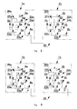
Fig.3 is a schematic view illustrating an oil balance operation between different units; -
Fig.4 is a schematic view illustrating the oil balance operation between different units; -
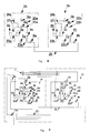
Fig.5 is a schematic view illustrating the oil balance operation between different units including only one compressor respectively; -
Fig.6 is a schematic view illustrating an oil reservoir is installed in a simplified way; -
Fig.7 is a schematic view illustrating the configuration of air -cooled scroll chiller (heat pump) units according to a second embodiment of the present invention; -
Fig.8 is a schematic view illustrating the configuration of scroll water-cooled package units according to a third embodiment of the present invention; -
Fig.9 is a schematic view illustrating the configuration of duct type air conditioning units according to a fourth embodiment of the present invention; - Fin.10 is a schematic view illustrating the system arrangement of a check valve according to the present invention;
-
Fig.11 is a schematic view illustrating the structure of the check valve ofFig.10 ; -
Fig.12 is a cross section view illustrating the check valve ofFig. 10 along the line A-A. - A conditioner units system according to the present invention comprises a plurality of paralleled connected compressor units. Each compressor unit comprises one or more than one paralleled connected compressors. The oil balance between the different compressor units is realized by oil balance devices and corresponding oil balance operations.
- The one or more than one compressor units could be disposed in one or more than one refrigerating conditioner apparatuses, for an example, multi-air conditioners, water-cooled or air-cooled duct type air conditioner, scroll-type water-cooled or air-cooled chiller or heat pump, water-cooled package unit and so on. Of course, the application of the present invention should not be limited in the conditioner units describe above.
- The present invention takes a multi-air conditioners system for the example. Each outdoor unit includes a compressor unit and the outdoor units are connected by some gas pipes, liquid pipes and oil balance pipes. Furthermore, the outdoor units are connected to a plurality of indoor units by some gas pipes and liquid pipes to construct a refrigerating conditioning system.
- In the system each compressor unit comprises one or more than one paralleled connected compressors. The suction pipes and the exhaust pipes of the compressors are connected in parallel by some paralleled connected pipes. The paralleled connected compressors are interconnected by an oil balance pipe and a gas balance pipe.
- Each compressor unit comprises an oil reservoir and the oil reservoir constitutes an oil balance device with corresponding pipes and control valves. The oil balance device is connected to the compressors in parallel to realize not only the oil balance between the compressors and the oil reservoir, but also the balance between the oil reservoirs belonging to different compressor units.
- The oil balance device according to the prevent invention comprises one oil reservoir and the oil reservoir is connected to the exhaust pipe of the compressors through a first connecting pipe and a first control valve. The objective of the connection is that the exhaust pressure of the compressors could be used as a power to press the redundant oil in the oil reservoir into other units.
- The oil reservoir is connected to the gas balance pipe disposed between the compressors through a second connecting pipe and a second control valve. In addition, the oil reservoir is connected to the oil balance pipe through a third connecting pipe and a third control valve. The objective of the connections is that one connected vessels would be constructed between the oil cavity of the compressors and the oil reservoir. Therefore, the oil level in the compressors and the oil level in the oil reservoir would keep balancing. In another word, the oil quantity in the oil reservoir reflects the oil quantity in the compressors. In a normal working condition, the oil would automatically flow into the oil reservoir when the oil in the compressors is too much and the oil would automatically supplement to the compressors from the oil reservoir when the oil in the compressors is too little.
- The oil reservoir is connected to other oil reservoirs belonging to other units through a fourth connecting pipe and a fourth control valve. The opening and closing of the oil balance pipe between the units could be realized by the opening and closing of the fourth control valve to control the oil balance between the units.
- The first connecting pipe and the second connecting pipe also could be combined firstly and then connected to the oil reservoir.
- The fourth connecting pipe has better insert into the oil reservoir for a suitable protruding height. The protruding height depends on the size of the oil reservoir and the size of the compressors connecting to the oil reservoir. The objective of setting the protruding height is that enough oil would be remained in the oil reservoir when the oil in the oil reservoir is pressed into another unit. The oil would supplement to the compressors when the oil level in the compressors is too low in such a way the reliability of the compressors' running is improved.
- The oil balance between the conditioner units is realized by the controlling of related valves.
- Firstly, the oil balance between the compressors belonging to one compressor unit and the balance between the compressors and the oil reservoir would be performed. Due to the principle of connected vessels, in the interior of each unit the oil level of all the compressors and the oil level of the oil reservoir would keep balancing. The oil would flow into the oil reservoir through the connecting pipe if the oil level in the compressors is too high and the oil in the oil reservoir would automatically supplement to the compressors if the oil level in the compressors is too low. But the oil in the compressors would not flow out through an oil balance aperture once the oil level in the compressors is lower than the oil balance aperture. The height of the bottom of the oil reservoir is the same to that of an oil balance opening of the compressors, or the former is slightly higher, to ensure the redundant oil could flow into the oil reservoir.
- The oil balance between the compressor units is driven by the power provided by the exhaust pressure of the unit supplying the oil. Because the oil reservoir of the unit receiving the oil communicates with the gas balance pipe of the compressors, the redundant oil (the oil above the protruding height) would be pressed from the unit supplying the oil into the oil reservoir of the unit receiving the oil when the pressure in the oil reservoir of the unit supplying the oil is enhanced. Each compressor unit would perform the oil supplying and the oil receiving on by one in a certain order to carry out the oil cycling in such a way the oil balance between the oil reservoirs belonging to the different units is realized. In addition, the valve connecting the oil reservoir and the oil balance pipe of the compressors and the valve connecting the oil reservoir and the gas balance pipe of the compressors could be opened to realize the oil balance between the oil reservoir and the compressors.
- The present invention will be described further with details as following.
- With reference to
Fig. 1 , a multi-air conditioner units system comprises a plurality of same or different compressor units connected in parallel. A compressor unit 1a and acompressor unit 1b are connected in parallel. A section of anoil balance pipe 20 between twojunction valves compressor units 1a, 1b. Aliquid connecting pipe 30 and agas connecting pipe 40 connect thecompressor units 1a, 1b in parallel and also connect twoindoor units - The
indoor unit 15 includes anindoor heat exchanger 15a and anexpansion valve 15b. Theindoor unit 16 includes anindoor heat exchanger 16a and anexpansion valve 16b. Each indoor unit is connected to the liquid pipes and the gas pipes disposed between the indoor units and the outdoor units. - Because each compressor unit has a same structure, here the compressor unit 1a would be described as an example. The code of each component of the compressor unit 1a corresponds with that of the
compressor unit 1b, and the suffix are a and b respectively. - As shown in
Fig.1 , the compressor unit 1a includes twocompressors compressors point 26a and then thepoint 26a is connected to anoil separator 9a. The exhaust port of theoil separator 9a is connected to a four-way valve 10a. The lubricating oil gets though acapillary tube 14a and back to asuction pipe 21a and then enters into the compressors. The other three interfaces of the four-way valve 10a are connected to acondenser 11a, a gas-liquid separator 13a and thegas connecting pipe 40 respectively. Thecondenser 11a is connected to aliquid reservoir 12a (theliquid reservoir 12a could be cancelled sometimes basing on the demand of the design of the system) and subsequently is connected to an indoor unit through theliquid connecting pipe 30. - The inlet of the gas-
liquid separator 13a is connected to the four-way valve 10a and the outlet is connected to thesuction pipe 21a. The refrigerant is divided in thesuction pipe 21a and is sucked into thecompressors - The top of an
oil reservoir 4a is connected to theexhaust pipe 26a through a 1#valve 5a so that the high pressure gas in the compressor could be introduced into theoil reservoir 4a to provide a power for the cycling of the lubricating oil in different units. Agas balance pipe 27a is disposed between the paralleledconnected compressors oil reservoir 4a is connected to thegas balance pipe 27a through a 2# valve 6a so that the balance of gas pressure between theoil reservoir 4a and thecompressors - An
oil balance pipe 22a is disposed between thecompressors 2a, 3a.Theoil reservoir 4a is connected to theoil balance pipe 22a through anotheroil balance pipe 23a and a 3#valve 7a.The connections between thegas balance pipe 24a, theoil balance pipe 23a and thecompressors connected compressors compressors oil reservoir 4a. Furthermore, basing on the principle of connected vessels, the oil level in theoil reservoir 4a and the oil level in thecompressors compressors oil reservoir 4a through theoil balance pipe 23a. When the oil level in thecompressors oil reservoir 4a will automatically supplement to thecompressors compressors oil reservoir 4a due to the principle of connected vessels. Conversely, the oil in theoil reservoir 4a will automatically supplement to the compressors when the oil level in the compressors is too low. - The
oil balance pipe 20 is connected to other units through a 4# valve 8a to realize the lubricating oil supply between thedifferent units 1a, 1b. - A section of pipe disposed between the bottom of the
oil reservoir 4a and the 4# valve 8a has better protrude into theoil reservoir 4a for a suitable protruding height and the protruding height depends on the size of theoil reservoir 4a and the size of the compressors. The objective of setting the protruding height is to remain enough oil to prevent the too low oil level in thecompressors oil reservoir 4a is pushed to anotherunit 1b. The setting the protruding height could improve the operation reliability of the compressors. - For illustration,
Fig.2 only shows the combination parts relating to the oil balance. The code of each component of the compressor unit 1a corresponds with that of thecompressor unit 1b, and the suffix are a and b respectively. The oil balance operation will be described as following according toFig.2 . - When the oil balance is operated, all the valves in the units should be operated as shown in table 1:
Table 1 Unit 1a Unit 1bCompressor 1 # valve 5a2 # valve 6a3 # valve 7a4 # valve 8aCompressor 1 # valve 5b2 # valve 6b3 # valve 7b4 # valve 8bNormal Working Condition Normal Runnmg closed open open closed Normal Runnmg closed open open closed Operation 1: unit 1a supplies oil, unit 1b receives oilopen closed closed open closed open closed open operation 2: unit 1b supplies oil, unit 1a receives oilclosed open closed open open closed closed open - It must be noted that at least one of all the units involved in the oil balance operation between the compressor units has a compressor on running and all the compressors on running are normally controlled by a regulator rule. The regulator rule has no influence to the oil balance operation between the units, and vice versa.
- In a normal operation, the 2
#valve 6a and the 3#valve 7a are opened, while the 1#valve 5a and the 4#valve 8a are closed. The pressure balance between theoil reservoir 4a and thecompressors gas balance pipe 24a and thegas balance pipe 27a of thecompressors oil balance pipe 23a and theoil balance pipe 22a of thecompressors compressors oil reservoir 4a. When the oil level in thecompressors oil reservoir 4a through theoil balance pipe 23a. When the oil level in thecompressors oil reservoir 4a will automatically supplement to the compressors. Furthermore, the oil in the compressors will not flow into theoil reservoir 4a through the oil balance aperture once the oil level in thecompressors - As shown in
Fig.3 , during anoperation 1, the unit 1a supplies oil toother unit 1b firstly. The 1#valve 5a of unit 1a is open to load the exhaust pressure onto theoil reservoir 4a. At the same time the 2#valve 6a and the 3#valve 7a are closed not only to prevent gas flow short-circuit ,but also to prevent the oil flowing back into thecompressors #valve 7a. In such a way, the redundant oil (the oil above the protruding height) in the unit 1a will flow into theunit 1b through the 4#valve 8a. Simultaneously, the 4#valve 8b of theunit 1b opens and the redundant oil from the unit 1a could flow into anoil reservoir 4b of theunit 1b. A 2#valve 6b of theunit 1b will open to exhaust the gas in theoil reservoir 4b to prevent the pressure rising in theoil reservoir 4b which cases the lubricating oil could not flow into theoil reservoir 4b. A 1#valve 5b and the 3#valve 7b ofunit 1b are all closed. - The oil reservoir according to the present invention is designed specially and the section of pipe disposed between the bottom of the
oil reservoir 4a and the 4#valve 8a inserts into theoil reservoir 4a for the protruding height. During theoperation 1, when the oil level in theoil reservoir 4a is higher than the protruding height, it could be considered that the oil level in the unit 1a is higher than a design value. Due to the effect of the exhaust pressure, the redundant oil will be transferred to theoil reservoir 4b of theother unit 1b. When the oil level in theoil reservoir 4a is lower than the protruding height, it could be considered that the oil level in the unit 1a is lower than the design valve and no oil flows into other units. Because the oil in the whole units is sufficient to satisfy the lubrication of the whole units, theoil reservoir 4b of theunit 1b would not be short of the oil even at the end of theoperation 1. The unit 1a will be waiting for an operation 2 in which other units will supply oil to it. - Referring to
Fig.4 , during the operation 2, the 1#valve 5b of theunit 1b opens to load the exhaust pressure of the compressors onto theoil reservoir 4b. Meanwhile, the 2#valve 6b and the 3#valve 7b are closed not only to prevent gas flow short-circuit ,but also to prevent the oil flowing back into thecompressors #valve 7b. In such a way, the lubricating oil in theunit 1b will flow into the unit 1a through the open 4#valve 8b. Simultaneously, the 4#valve 8a of the unit 1a opens and the oil from theunit 1b could flow into theoil reservoir 4a of the unit 1a. The 2#valve 6a of the unit 1a will open to exhaust the gas in theoil reservoir 4a to prevent the pressure rising in theoil reservoir 4a which cases the lubricating oil could not flow into theoil reservoir 4a. The 1#valve 5a and the 3#valve 7a are all closed. Therefore, theoil reservoir 4a of the unit 1a originally shorting of oil gets oil supplement. Meanwhile, theoil reservoir 4b of theunit 1b remains enough lubricating oil for the use by itself and the redundant oil is discharged. - If the system includes more units 1c, 1d, the oil supply from the
unit 1b to the units 1c will be processed once the oil supply from the unit 1a tounit 1b is finished. Next the supply from the unit 1c to unit 1d will be processed once the supply from theunit 1b to unit 1c is finished. Similarly, the similar oil supply operation will be processed one by one until the oil reaches the last unit .Next the oil would flows back from the last unit to other units in a reverse order until the oil reaches the first unit. For an example, in a system comprising four units, the sequence of the loop is a→b→c→d ,and next is d→c→b→a in a reverse order. The above sequence is not unique and the main feature is that the lubricating oil in the system will pass through each unit in the forward and reverse order to leave a certain volume of oil in each oil reservoir of each unit to ensure the need of the oil balance in the system. - When the balance operation is done between the units, the units would be in normal operation condition. The
#2valve #valve #valve #valve - When the oil balance is operated, all the valves in the units should be operated as shown in table 2:
Table 2 Unit 1a Unit 1bCompressor 1 # valve 5a2 # valve 6a3 # valve 7a4 # valve 8aCompressor 1 # valve 5b2 # valve 6b3 # valve 7b4 # valve 8bNormal Working Condition Normal Runnmg closed open open closed Normal Runnmg closed open open closed Operation 1: unit 1a supplies oil, unit 1b receives oilopen closed closed open closed closed open open Operation 2: unit 1b supplies oil, unit 1a receivers oilclosed closed open open open closed closed open - In a normal working condition, the 2
#valve 6a and the 3#valve 7a are open and the 1#valve 5a and the 4#valve 8a are closed. The pressure balance between the oil reservoir and the compressors would be realized by the connection of thegas balance pipe 24a and the gas balance pipe of the compressors. Basing on the principle of connected vessels, the connection of theoil balance pipe 23a and theoil balance pipe 22a of the compressors could realize not only the balance between thecompressors oil reservoir 4a. The oil in the compressors will flow into theoil reservoir 4a through theoil balance pipe 23a if the oil level in thecompressors oil reservoir 4a will automatically supplement to the compressors if the oil level in thecompressors compressors - In an
operation 1, the unit 1a supplies oil to other units firstly. The 1#valve 5a is open to load the exhaust pressure of the compressors onto theoil reservoir 4a. Simultaneously, the 2#valve 6a and the 3#valve 7a are closed to prevent not only the gas flow short-circuit ,but also the oil flowing back into thecompressors #valve 7a. In such a way, the redundant oil (the oil above the protruding height) in the unit 1a will flow into theunit 1b through the open 4# valve 8a. Meanwhile, the 4#valve 8b and the 3#valve 7b are open, and the 1#valve 5b and 2#valve 6b are closed. The redundant oil from the unit 1a will pass through theoil reservoir 4b and flow into thecompressors - After a period of time of normal working condition of the unit 1a and
unit 1b, the 2#valve #valve #valve #valve - The operation 2 is executed after a period time of normal working condition. The
unit 1b supplies oil to unit 1a and the 1#valve 5b is opened to load the exhaust pressure of the compressors onto theoil reservoir 4b. Simultaneously, the 2#valve 6b and the 3#valve 7b are closed to prevent not only the gas flow short-circuit, but also the oil flowing back into thecompressors #valve 7b. In such a way, the redundant oil (the oil above the protruding height) in theunit 1b will flow into the unit 1a through the open 4# valve 8b. Meanwhile, the 4#valve 8a and the 3#valve 7a are opened and the 1#valve 5a and the 2#vave 6a are closed. The redundant oil from theunit 1b will pass through theoil reservoir 4a and flow into thecompressors - Because the oil in the whole units is sufficient to satisfy the lubrication of the whole units, the
oil reservoir 4b of theunit 1b would not be short of the oil even after theoperation 1. Theoil reservoir 4a and the compressors of the unit 1a originally shorting of oil gets oil supplement after the operation 2. Meanwhile, theoil reservoir 4b of theunit 1b remains enough lubricating oil for the use by itself and the redundant oil are discharged. - If the system includes more units 1c, 1d, the oil supply from the
unit 1b to the units1c will be processed once the oil supply from the unit 1a tounit 1b is finished. Next the supply from the unit 1c to unit 1d will be processed once the supply from theunit 1b to unit 1c is finished. Similarly, the oil supply operation will be processed one by one until the oil reaches the last unit .Next the oil would flow back from the last unit to other units in a reverse order until the oil reaches the first unit. For an example, in a system comprising four units, the sequence of the loop is a→b→c→d, and next is d→c→b→a in a reverse order. The above sequence is not unique and the main feature is that the lubricating oil in the system will pass through each unit in the forward and reverse order to leave a certain volume of oil in each oil reservoir of each unit to ensure the need of the oil balance in the system. - The unit receiving the oil would be in normal working condition for a period of time after the oil receiving is done to balance the oil levels of the compressors and the oil reservoir. Then another following operation will be executed.
- Referring to
Fig.5 , if each unit comprises only one compressor (the twocompressors gas balance pipe 24a of the oil reservoir is connected to a gas balance opening of the compressor andoil balance pipe 23a of the oil reservoir is connected to an oil balance opening of the compressor. In such a way, both the gas balance and the oil balance between the single compressor and the oil reservoir could be realized. The concrete implementation manner is the same to that of the multi-compressors system. - The
gas balance pipe 24a and anexhaust connecting pipe 25a of theoil reservoir 4a could be separately connected to theoil reservoir 4a and also could be combined together firstly and then connected to theoil reservoir 4a as shown inFig.6 . - The present invention is not only suitable for multi-air conditioners system, but also suitable for chiller (heat pump) units system comprising a plurality of paralleled connected compressors, multi-connected air conditioners; water-cooled or air-cooled duct type air conditioner; scroll-type water-cooled or air-cooled chiller or heat pump, water-cooled package unit and so on. The conditioning systems comprise two or more than two paralleled connected compressor units and the units are connected in parallel by the pipes of high-pressure side and low-pressure side to construct a refrigerating cycling. Furthermore, the oil lines of the compressor units are connected together by the oil balance device according to the present invention which realizes the oil balance between the units.
- Referring to
Fig.7 , it illustrates a second embodiment of the prevent invention. The concept of the second embodiment according to the present invention is approximately similar to the concept of multi-air conditioners. For the convenience of description, the compressor unit on the left is named 1a and the compressor unit on the right is named 1b. The connecting of pipes and the corresponding definitions are essentially consistent in the unit 1a andunit 1b so that it is unnecessary to go into details. The difference is that because the whole system is integrated into one shell the heat exchanger of the unit 1a and the heat exchanger of theunit 1b are combined into awhole heat exchanger 11. The twounits 1a, 1b use a same liquid reservoir 12(theliquid reservoir 12 could be neglected sometimes basing on the design of the system) in such a way the outlets of the four-way valves of the unit 1a and theunit 1b are combined firstly and then connected to theheat exchanger 11. The system also comprises anindoor heat exchanger 16 and anexpansion valve 16a. Theheat exchanger 11 could be set in an outdoor system to make heat exchange with the refrigerating system by a second medium to transfer the cold or heat to the indoor system, for an example, the air -cooled chiller (heat pump) units. Theheat exchanger 11 also could be such an exchanger on which the air makes heat exchanges with the refrigerant directly and such a heat exchanger could be disposed in one shell with a compressor system, for an example, the water-cooling tank-type air-conditioning units. The heat exchanger is also could be disposed on an indoor side, for an example, air-cooled duct type air conditioners. The air makes heat exchange with the heat exchanger and sent to the indoor. The oil balance operation of the embodiment is substantially the same to that of the multi-air conditioners system so it is unnecessary to go into details again. - Referring to
Fig. 8 , it illustrates a third embodiment of the present invention. The third embodiment makes some small changes on the basis of the second embodiment illustrated inFig.7 to satisfy the different applications. The unit 1a and theunit 1b use a same gas-liquid separator 13 and a same four-way valve 10. In such a way, the suction pipes of the unit 1a and theunit 1b converge at the gas-liquid separator 13. Theexhaust pipe 26a of the unit 1a and theexhaust pipe 26b of theunit 1b converge firstly and than are connected to the four-way valve 10. The other parts of the embodiment are consistent to the corresponding parts of the second embodiment. - Of course, the exhaust pipes of
units 1a, 1b could be connected to their respective four-way valves, likely as illustrated inFig. 7 . After getting through the four-way valves, the exhaust pipes ofunits 1a, 1b are combined and connected to theheat exchanger 11, as illustrated inFig.9 . - Furthermore, for some special applications, for an example, when two paralleled connected compressors are disposed in one shell, the
control valves oil balance pipe 20 as illustrated inFig.7 ,8 ,9 could be combined into one control valve. - The 1#~4# valves in the oil balance device of the present invention are controlled to realize the connection and the disconnection of the pipes. The valves could be electromagnetic valves controlled by controllers, or also could be electronic expansion valves (EEVs) controlled by controllers. The EEVs could be opened to a certain extent or closed to realize the connection and the disconnection of the pipes, basing on the demand of the oil balance operation. The EEV could be used to control the pressure difference by controlling the extent of the opening of the EEV, especially for the 1#valve. Of course, the 1#~4#valves also could be other electric or mechanic valves having the similar features. In addition, the valves could be disposed in the interior of the pipes or disposed on the junction of the pipes.
- The valves described above, especially the
valves operation 1 to establish a high pressure in the oil reservoir to press the oil out and the valves could be opened during the operation 2 to exhaust the gas in the oil reservoir to realize the oil receiving. - The present invention also disclosures a check valve designed specially to realize the function of the valves described above in a better way.
Fig. 10 illustrates the system layout andFig. 11 illustrates the structure of the check valve. - Generally, known common check valve is consisted of a
valve plate 55, a magnet 53, an upper valve seat 50, alower valve seat 51 and a shell made of copper tube. To satisfy the requirement of the feature of the check valve that being accessible in positive direction and being cut-off in negative direction, the lower end surface of the upper valve seat 50 is a contactingsurface 56. A step is formed in the middle of thelower valve seat 51 and defines a contactingsurface 52 and a plurality of guiding slots are formed on the circumference of thelower valve seat 51 as shown inFig. 12 . - The difference between the check valve of the present invention and the common check valve is that at least one
aperture 54 is formed on thevalve plate 55 basing on the design condition and the magnet 53 is embedded in thelower valve seat 51 to ensure the check valve is open on the condition of no pressure difference or slight pressure difference. - In the normal working condition, the
valve 6a is forced to open and thevalve plate 55 abuts the contactingsurface 52 tightly under the magnetic force of the magnet 53 and the gravity. Due to the guiding slots formed on thevalve seat 51, the valve is on the status of open to realize the gas balance between the oil reservoir and the compressors. In theoperation 1, the unit 1a supplies oil. Thevalve 5a is open and the high pressure gas gets into the oil reservoir. Thevalve plate 55 overcomes the magnetic force and the gravity and abuts the contactingsurface 56 tightly under the pressure difference and thus the valve is closed. The size of theaperture 54 formed on thevalve plate 55 depends on the design condition. When the valve is closed, the gas leakage brought by theaperture 54 could be ignored and the leakage would not influence the close of the valve. The objective of setting theaperture 54 is that the high pressure could be inducted and the high pressure could be unloaded when thevalve 6a changes from the close status to the open status. For an example, thevalve 5a would close after the oil discharging is done and the high pressure of the gas in the oil reservoir would be unloaded through theaperture 54. Meanwhile, thevalve plate 55 of thevalve 6a would automatically abut the contactingsurface 52 under the magnetic force and the gravity and thus thevalve 6a is opened. In the operation 2, the unit 1a receives oil. Thevalves check valve 6a overcomes the magnetic force and the gravity and is closed under a high pressure difference. Theaperture 54 formed on thevalve plate 55 discharges the gas in the oil reservoir to make sure the oil could flow into the oil reservoir smoothly. - According to the present invention, it could be realized that the redundant oil is discharged and simultaneously the enough oil is remained for the use of the unit. Therefore, the oil balance could be achieved without the using of special oil level testing instruments just the oil cycling between the different oil reservoirs is carried out regularly.
- The oil balance operation doesn't need the cooperation of the compressors to perform the on/off operations and each compressor just runs under the normal control of the system. The compressors don't need to repeat the on/off operations frequently so that the life of the compressors would not be shorted.
- The oil cycling between the different units is driven by the exhaust pressure of the compressors so that a certain extent of the installation height gap is permitted and the length of the oil balance pipe is not restricted strictly. The advantages make the design more freely and also makes the oil balance time shorter.
- The present invention could supply oil to each compressor equably so the running of the units is more reliable.
- The present invention could realize the oil balance reliably and effectively in the normal working condition of the units.
Claims (32)
- An oil balance device, comprising:an oil reservoir;a first pipe communicating with the oil reservoir;a second pipe communicating with the oil reservoir;a third pipe communicating with the oil reservoir;a fourth pipe communicating with the oil reservoir;wherein each pipe is provided with at least one valve to control the opening and the closing of the corresponding pipe.
- The oil balance device according to claim 1, wherein both the first pipe and the second pipe communicate with the top of the oil reservoir and both the third pipe and the fourth pipe communicate with the bottom of the oil reservoir.
- The oil balance device according to claim 2, wherein the end communicating with the bottom of the oil reservoir of the fourth pipe inserts into the interior of the oil reservoir for a certain height.
- The oil balance device according to claim 1, wherein the first pipe and the second pipe communicate with the oil reservoir independently and respectively.
- The oil balance device according to claim 1, wherein the first pipe and the second pipe comprise a shared pipe communicating with the oil reservoir.
- The oil balance device according to claim 1, wherein the valve is disposed in the interior of the corresponding pipe.
- A compressor unit, comprising:at least a compressor;at least an oil balance device, the oil balance device comprising:an oil reservoir;a first pipe, wherein one end of the first pipe communicates with the oil reservoir and the other end communicates with the exhaust pipe of the compressor;a first valve for controlling the on/off of the first pipe;a second pipe, wherein one end of the second pipe communicates with the oil reservoir and the other end communicates with the gas balance opening of the compressor;a second valve for controlling the on/off of the second pipe;a third pipe, wherein one end of the third pipe communicates with the oil reservoir and the other end communicates with the oil balance opening of the compressor;a third valve for controlling the on/off of the third pipe;a fourth pipe, wherein one end of the fourth pipe communicates with the oil reservoir and the other end communicates with another oil reservoir belonging to a neighboring compressor unit;a fourth valve for controlling the on/off of the fourth pipe.
- The compressor unit according to claim 7, wherein the second pipe communicates with the gas balance opening of the compressor through a gas balance pipe of the compressor.
- The compressor unit according to claim 7, wherein the third pipe communicates with the oil balance opening of the compressor through an oil balance pipe of the compressor.
- The compressor unit according to claim 7, wherein the height of the bottom of the oil reservoir is not lower than the height of the oil balance opening of the compressor.
- The compressor unit according to claim 7, wherein both the first pipe and the second pipe communicate with the top of the oil reservoir, and both the third pipe and the fourth the pipe communicate with the bottom of the oil reservoir.
- The compressor unit according to claim 7, wherein the end communicating with the bottom of the oil reservoir of the fourth pipe inserts into the interior of the oil reservoir for a certain height.
- The compressor unit according to claim 7, wherein the first pipe and the second pipe communicate with the oil reservoir independently and respectively.
- The compressor unit according to claim 7, wherein the first pipe and the second pipe comprise a shared pipe communicating with the oil reservoir.
- The compressor unit according to claim 7, wherein the first valve, the second valve, the third valve and the fourth valve are disposed in the interior of the first pipe, the second pipe, the third pipe and the fourth the pipe respectively.
- The compressor unit according to claim 7, wherein the fourth valve is shared by the two neighboring compressor units if the two compressor units are arranged in the interior of one shell.
- The compressor unit according to claim 7, wherein the second valve comprises a valve plate, a magnet below the valve plate and an aperture formed on the valve plate, wherein the size of the aperture makes no influence to the closing of the second valve and pressure difference between the two sides of the valve plates is unloaded when the second valve is switched from the off status to the on status.
- A method for performing an oil balance operation between a plurality of compressor units, comprising:providing an oil reservoir for each compressor unit;providing a first pipe, a second pipe, a third pipe and a fourth pipe for each compressor unit;connecting the first pipe to the oil reservoir of one compressor unit and to the exhaust pipe of the compressor;connecting the second pipe to the oil reservoir of the compressor unit and to the gas balance opening of the compressor;connecting the third pipe to the oil reservoir of the compressor unit and to the oil balance opening of the compressor;connecting the fourth pipe to the oil reservoir of the compressor unit and to another oil reservoir belonging to an neighboring compressor unit;controlling the on/off status of first pipe, the second pipe, the third pipe and the fourth pipe by a first valve, a second vale ,a third valve and a fourth valve respectively;closing the first valve and the fourth valve and opening the second valve and the third valve for the compressor units in a normal working condition;opening the first valve and the fourth valve and closing the second valve and the third valve for the compressor units supplying oil;opening the second valve and the fourth valve and closing the first valve and the third valve, or opening the third valve and the fourth valve and closing the first valve and the second valve, for the compressor units receiving oil.
- The method according to claim 18, wherein the compressor unit works in the normal working condition for a period of time before staring the oil supplying.
- The method according to claim 18, wherein the compressor unit works in the normal working condition for a period of time after finishing the oil receiving.
- The method according to claim 18, wherein the two compressor units which supplying the oil and receiving the oil respectively are neighboring.
- The method according to claim 18, wherein the neighboring compressor units supply and receive the oil respectively.
- The method according to claim 18, wherein the supplying and the receiving of the oil are performed one by one among the compressor units and reversely in a following turn.
- The method according to claim 18, wherein the second pipe communicates with the gas balance opening of the compressor through the gas balance pipe of the compressor.
- The method according to claim 18, wherein the third pipe communicates with the oil balance opening of the compressor through the oil balance pipe of the compressor.
- The method according to claim 18, wherein the height of the bottom of the oil reservoir is not lower than the height of the oil balance opening of the compressor.
- The method according to claim 18, wherein the first pipe and the second pipe communicate with the top of the oil reservoir, and the third pipe and the fourth pipe communicate with the bottom of the oil reservoir.
- The method according to claim 18, wherein the end communicating with the bottom of the oil reservoir of the fourth pipe inserts into the interior of the oil reservoir for a certain height.
- The method according to claim 18, wherein the first pipe and the second pipe communicate with the oil reservoir independently and respectively.
- The method according to claim 18, wherein the first pipe and the second pipe comprise a shared pipe communicating with the oil reservoir.
- The method according to claim 18, wherein the first valve, the second valve, the third valve and the fourth valve are disposed in the interior of the first pipe, the second pipe, the third pipe and the fourth the pipe respectively.
- The method according to claim 18, wherein the fourth valve is shared by the two neighboring compressor units if the two compressor units are arranged in the interior of one shell.
Applications Claiming Priority (2)
| Application Number | Priority Date | Filing Date | Title |
|---|---|---|---|
| CN 200810161327 CN101676564A (en) | 2008-09-19 | 2008-09-19 | Oil balancing device, compressor unit and oil balancing method thereof |
| PCT/CN2009/001040 WO2010031250A1 (en) | 2008-09-19 | 2009-09-17 | Oil equalizing device, compressor unit and oil equalizing method |
Publications (2)
| Publication Number | Publication Date |
|---|---|
| EP2336681A1 true EP2336681A1 (en) | 2011-06-22 |
| EP2336681A4 EP2336681A4 (en) | 2014-08-06 |
Family
ID=42029240
Family Applications (1)
| Application Number | Title | Priority Date | Filing Date |
|---|---|---|---|
| EP09813971.0A Withdrawn EP2336681A4 (en) | 2008-09-19 | 2009-09-17 | Oil equalizing device, compressor unit and oil equalizing method |
Country Status (4)
| Country | Link |
|---|---|
| US (1) | US8959947B2 (en) |
| EP (1) | EP2336681A4 (en) |
| CN (1) | CN101676564A (en) |
| WO (1) | WO2010031250A1 (en) |
Cited By (2)
| Publication number | Priority date | Publication date | Assignee | Title |
|---|---|---|---|---|
| WO2013007310A1 (en) * | 2011-07-14 | 2013-01-17 | Carrier Corporation | Refrigeration circuit with oil compensation |
| JPWO2018116407A1 (en) * | 2016-12-21 | 2019-10-24 | 三菱電機株式会社 | Refrigeration cycle equipment |
Families Citing this family (13)
| Publication number | Priority date | Publication date | Assignee | Title |
|---|---|---|---|---|
| JP5805186B2 (en) * | 2011-06-09 | 2015-11-04 | 三菱電機株式会社 | Air conditioner indoor unit |
| CN102338505A (en) * | 2011-09-30 | 2012-02-01 | Tcl空调器(武汉)有限公司 | Oil return flow path for multi-connected compressors and control method of oil return flow path |
| JPWO2013099047A1 (en) * | 2011-12-27 | 2015-04-30 | 三菱電機株式会社 | Air conditioner |
| CN102889712B (en) * | 2012-10-22 | 2015-03-11 | 海尔集团公司 | Multi-connected air-conditioning unit and oil balancing system thereof |
| JP5751355B1 (en) * | 2014-01-31 | 2015-07-22 | ダイキン工業株式会社 | Refrigeration equipment |
| KR102165351B1 (en) | 2014-02-05 | 2020-10-13 | 엘지전자 주식회사 | A heat-pump system and a method controlling the same |
| JP6293647B2 (en) * | 2014-11-21 | 2018-03-14 | ヤンマー株式会社 | heat pump |
| CN205279498U (en) | 2015-10-15 | 2016-06-01 | 丹佛斯(天津)有限公司 | Oil air balance device and use its compressor system thereof |
| JP6552939B2 (en) * | 2015-10-22 | 2019-07-31 | 三菱重工サーマルシステムズ株式会社 | Air conditioning system |
| CN109154461A (en) | 2016-05-25 | 2019-01-04 | 开利公司 | For freely cooling down air cooling and the water-cooled freezer unit of application |
| CN110806036B (en) * | 2019-10-22 | 2024-08-20 | 珠海格力电器股份有限公司 | Oil return control and compressor variable capacity control system of heat pump and air conditioner |
| CN116067044A (en) * | 2021-11-01 | 2023-05-05 | 广东美的暖通设备有限公司 | Compressor assembly, air conditioner outdoor unit and air conditioning system |
| CN114810553B (en) * | 2022-06-28 | 2022-09-13 | 山东宏泰电器有限公司 | Oil supply mechanism of variable frequency compressor |
Family Cites Families (20)
| Publication number | Priority date | Publication date | Assignee | Title |
|---|---|---|---|---|
| US3500962A (en) * | 1969-05-01 | 1970-03-17 | Vilter Manufacturing Corp | Lubrication system for compressors |
| US3719507A (en) * | 1971-03-01 | 1973-03-06 | W Bardeau | Cooking appliance |
| US4478050A (en) * | 1982-11-19 | 1984-10-23 | Hussmann Corporation | Oil separation for refrigeration system |
| BR8502912A (en) * | 1985-06-14 | 1985-10-08 | Narcizo Osorio Basseggio | CARTER CAMERA |
| JP2656627B2 (en) * | 1989-08-02 | 1997-09-24 | 株式会社日立製作所 | Oil supply device for hermetic scroll compressor |
| BR8905970A (en) * | 1989-11-16 | 1991-05-21 | Narcizo Osorio Basseggio | MISCIBLE FLUID COMPRESSION SYSTEM AND PROCESS |
| PT672875E (en) * | 1994-03-15 | 2000-11-30 | Mitsubishi Electric Corp | AIR CONDITIONING SYSTEM, ACCUMULATOR FOR THE SAME AND PROCESS FOR THE ACCUMULATING MANUFACTURING |
| AU2706301A (en) * | 2000-01-21 | 2001-07-31 | Toshiba Carrier Corporation | Oil amount detector, refrigeration apparatus and air conditioner |
| JP4499863B2 (en) * | 2000-01-21 | 2010-07-07 | 東芝キヤリア株式会社 | Multi-type air conditioner |
| TWI237682B (en) * | 2000-07-07 | 2005-08-11 | Sanyo Electric Co | Freezing apparatus |
| JP3937884B2 (en) * | 2002-03-22 | 2007-06-27 | 三菱電機株式会社 | Refrigeration air conditioner |
| KR100694915B1 (en) * | 2003-02-27 | 2007-03-14 | 도시바 캐리어 가부시키 가이샤 | Refrigeration cycle unit |
| JP3685180B2 (en) * | 2003-04-14 | 2005-08-17 | ダイキン工業株式会社 | Hermetic compressor |
| CN2670861Y (en) * | 2003-12-05 | 2005-01-12 | 广东美的集团股份有限公司 | Oil balancing device in compressor of air conditioner |
| JP3939314B2 (en) | 2004-06-10 | 2007-07-04 | 三星電子株式会社 | Air conditioner and oil equalizing operation method thereof |
| US20060073026A1 (en) * | 2004-10-06 | 2006-04-06 | Shaw David N | Oil balance system and method for compressors connected in series |
| KR20060055154A (en) * | 2004-11-18 | 2006-05-23 | 엘지전자 주식회사 | Compressor Oil Recovery Unit of Multi-type Air Conditioner |
| CN101093121B (en) * | 2006-06-21 | 2010-05-26 | 海尔集团公司 | A multi-connected air conditioner unit oil balance device |
| JP5029326B2 (en) * | 2007-11-30 | 2012-09-19 | ダイキン工業株式会社 | Refrigeration equipment |
| EP2177760A1 (en) * | 2008-05-23 | 2010-04-21 | Panasonic Corporation | Fluid machine and refrigeration cycle device |
-
2008
- 2008-09-19 CN CN 200810161327 patent/CN101676564A/en active Pending
-
2009
- 2009-09-17 EP EP09813971.0A patent/EP2336681A4/en not_active Withdrawn
- 2009-09-17 WO PCT/CN2009/001040 patent/WO2010031250A1/en not_active Ceased
-
2011
- 2011-03-17 US US13/050,116 patent/US8959947B2/en active Active
Cited By (4)
| Publication number | Priority date | Publication date | Assignee | Title |
|---|---|---|---|---|
| WO2013007310A1 (en) * | 2011-07-14 | 2013-01-17 | Carrier Corporation | Refrigeration circuit with oil compensation |
| JPWO2018116407A1 (en) * | 2016-12-21 | 2019-10-24 | 三菱電機株式会社 | Refrigeration cycle equipment |
| EP3561410A4 (en) * | 2016-12-21 | 2020-02-12 | Mitsubishi Electric Corporation | REFRIGERATION CYCLE DEVICE |
| EP3913299A1 (en) * | 2016-12-21 | 2021-11-24 | Mitsubishi Electric Corporation | Refrigeration cycle apparatus |
Also Published As
| Publication number | Publication date |
|---|---|
| US20110162746A1 (en) | 2011-07-07 |
| CN101676564A (en) | 2010-03-24 |
| WO2010031250A1 (en) | 2010-03-25 |
| US8959947B2 (en) | 2015-02-24 |
| EP2336681A4 (en) | 2014-08-06 |
Similar Documents
| Publication | Publication Date | Title |
|---|---|---|
| EP2336681A1 (en) | Oil equalizing device, compressor unit and oil equalizing method | |
| US6722156B2 (en) | Refrigeration system | |
| US8312731B2 (en) | Refrigeration apparatus and method for controlling the same | |
| US6928828B1 (en) | Tandem compressors with economized operation | |
| US20180340700A1 (en) | Variable refrigerant flow system | |
| US6955058B2 (en) | Refrigerant cycle with tandem economized and conventional compressors | |
| JP2009150628A (en) | Oil leveling system for high pressure shell compressor used in air conditioner | |
| EP1666806A2 (en) | Multi-air condition system and method for controlling the same | |
| EP2241843A2 (en) | Refrigeration cycle apparatus | |
| CN105352064A (en) | Outdoor unit, multi-connected outdoor unit system, multi-connected air-conditioning unit and oil uniformization control method of multi-connected air-conditioning unit | |
| CN100526731C (en) | Multi-air conditioner | |
| CN209101597U (en) | Multi-split air conditioner circulating system and multi-split air conditioner | |
| KR102904352B1 (en) | Air conditioning apparatus and a water supplying method of the same | |
| US20230049970A1 (en) | Air conditioning apparatus | |
| CN109307385B (en) | Air conditioning system, compression oil supply device and control method thereof | |
| EP2126476B1 (en) | Air conditioning system and control method for the same | |
| US11397015B2 (en) | Air conditioning apparatus | |
| US20060090505A1 (en) | Refrigerant cycle with tandem compressors for multi-level cooling | |
| CN100487346C (en) | Air conditioner | |
| JP2017110820A (en) | Air conditioning device | |
| CN114450543A (en) | Air conditioner | |
| KR101622225B1 (en) | Air conditioner | |
| KR100744774B1 (en) | Air conditioner | |
| CN108072190A (en) | Air conditioning system and air conditioner with same | |
| KR20040020615A (en) | Apparatus controlling oil balancing in an air-conditioner multi type and method thereof |
Legal Events
| Date | Code | Title | Description |
|---|---|---|---|
| PUAI | Public reference made under article 153(3) epc to a published international application that has entered the european phase |
Free format text: ORIGINAL CODE: 0009012 |
|
| 17P | Request for examination filed |
Effective date: 20110419 |
|
| AK | Designated contracting states |
Kind code of ref document: A1 Designated state(s): AT BE BG CH CY CZ DE DK EE ES FI FR GB GR HR HU IE IS IT LI LT LU LV MC MK MT NL NO PL PT RO SE SI SK SM TR |
|
| AX | Request for extension of the european patent |
Extension state: AL BA RS |
|
| DAX | Request for extension of the european patent (deleted) | ||
| A4 | Supplementary search report drawn up and despatched |
Effective date: 20140708 |
|
| RIC1 | Information provided on ipc code assigned before grant |
Ipc: F25B 31/00 20060101AFI20140702BHEP |
|
| STAA | Information on the status of an ep patent application or granted ep patent |
Free format text: STATUS: THE APPLICATION IS DEEMED TO BE WITHDRAWN |
|
| 18D | Application deemed to be withdrawn |
Effective date: 20150205 |