EP2336654A2 - Duct Type Air Conditioner - Google Patents
Duct Type Air Conditioner Download PDFInfo
- Publication number
- EP2336654A2 EP2336654A2 EP10168891A EP10168891A EP2336654A2 EP 2336654 A2 EP2336654 A2 EP 2336654A2 EP 10168891 A EP10168891 A EP 10168891A EP 10168891 A EP10168891 A EP 10168891A EP 2336654 A2 EP2336654 A2 EP 2336654A2
- Authority
- EP
- European Patent Office
- Prior art keywords
- fan
- panel
- inwardly
- panels
- vertical rails
- Prior art date
- Legal status (The legal status is an assumption and is not a legal conclusion. Google has not performed a legal analysis and makes no representation as to the accuracy of the status listed.)
- Withdrawn
Links
Images



Classifications
-
- F—MECHANICAL ENGINEERING; LIGHTING; HEATING; WEAPONS; BLASTING
- F24—HEATING; RANGES; VENTILATING
- F24F—AIR-CONDITIONING; AIR-HUMIDIFICATION; VENTILATION; USE OF AIR CURRENTS FOR SCREENING
- F24F13/00—Details common to, or for air-conditioning, air-humidification, ventilation or use of air currents for screening
- F24F13/20—Casings or covers
-
- F—MECHANICAL ENGINEERING; LIGHTING; HEATING; WEAPONS; BLASTING
- F24—HEATING; RANGES; VENTILATING
- F24F—AIR-CONDITIONING; AIR-HUMIDIFICATION; VENTILATION; USE OF AIR CURRENTS FOR SCREENING
- F24F1/00—Room units for air-conditioning, e.g. separate or self-contained units or units receiving primary air from a central station
- F24F1/0007—Indoor units, e.g. fan coil units
- F24F1/0071—Indoor units, e.g. fan coil units with means for purifying supplied air
-
- F—MECHANICAL ENGINEERING; LIGHTING; HEATING; WEAPONS; BLASTING
- F24—HEATING; RANGES; VENTILATING
- F24F—AIR-CONDITIONING; AIR-HUMIDIFICATION; VENTILATION; USE OF AIR CURRENTS FOR SCREENING
- F24F1/00—Room units for air-conditioning, e.g. separate or self-contained units or units receiving primary air from a central station
- F24F1/0007—Indoor units, e.g. fan coil units
- F24F1/0018—Indoor units, e.g. fan coil units characterised by fans
- F24F1/0033—Indoor units, e.g. fan coil units characterised by fans having two or more fans
-
- F—MECHANICAL ENGINEERING; LIGHTING; HEATING; WEAPONS; BLASTING
- F24—HEATING; RANGES; VENTILATING
- F24F—AIR-CONDITIONING; AIR-HUMIDIFICATION; VENTILATION; USE OF AIR CURRENTS FOR SCREENING
- F24F13/00—Details common to, or for air-conditioning, air-humidification, ventilation or use of air currents for screening
- F24F13/20—Casings or covers
- F24F2013/205—Mounting a ventilator fan therein
Definitions
- the present invention relates to a duct type air conditioner of which an improvement of a fan mechanism is intended.
- a fan mechanism As for a duct type air conditioner in the prior art, there is a technique to form a fan mechanism by assembling fans and motors with a fan panel, and the entire fan mechanism is received in a casing by mounting the fan panel inwardly of a front plate of a casing. Further, horizontal rails are provided on the upper and lower sides in the casing and said fan mechanism is withdrawn along the rails toward the left or right sides of the casing, so that maintenance is easily performed.
- the duct type air conditioner When, however, the duct type air conditioner is installed in a building, ducts for distributing discharged drafts needed to be provided around the casing.
- the upper rail is designed to be detachable such that the fan mechanism can be withdrawn in a vertical direction.
- the entire fan mechanism is tilted inwardly in the casing by the weight of the motors of the fan mechanism. As a result, there is a problem that the registration of screw holes for mounting a fan panel to the front plate remarkably lost.
- An object of the present invention is to provide a duct type air conditioner that does not cause the above-mentioned problem by providing a mechanism for the controlled descent of the fan mechanism.
- a duct type air conditioner including: a casing having discharge openings and a suction opening therein; said casing being composed of a front plate formed with a discharge duct mounting frame outwardly thereof so as to surround the discharge openings; a fan mechanism mounted inwardly of said front plate; said casing being further composed of a back plate formed with a suction duct mounting frame outwardly thereof so as to surround said suction opening; and a heat exchanger mounted inwardly of said back plate.
- the fan mechanism includes fan units having fan panels, motors mounted inwardly of said fan panels, and fans positioned inwardly of the fan panels and driven by the motors.
- a pair of L-shaped vertical rails is mounted on both sides of each of the discharge openings inwardly of the front plate so that the inner portions thereof face each other, and panel retainers are attached inwardly to the lower portions of the discharge openings. Press portions are formed at upper portions of both sides of the fan panels. Both edges of each fan panel are inserted into the vertical rails downward from above while being guided by the pair of vertical rails, the lower edge of the fan panel rides on the panel retainer, and the press portions of the fan panel are pushed down into the vertical rails, so that the fan panel is pressed against the inside of the front plate.
- each of the panel retainers includes an inclined surface portion opening inwardly and a stopper portion having a shape to form a bottom.
- a handle portion which is bent inward, is formed at an upper end of each of the fan panels.
- the discharge openings are substituted by the suction opening, the suction opening is substituted by the discharge openings, the discharge duct mounting frame is substituted by the suction duct mounting frame, and the suction duct mounting frame is substituted by the discharge duct mounting frame.
- fan units as a fan mechanism are completely mounted on the inside of the front plate. Accordingly, it is easy to mount the fan units on the inside of the front plate. Further, since the fan panel is mounted at a regular position while being pressed against the inside of the front plate, screw holes of the front plate naturally correspond to screw holes of the fan panels. As a result, it is easy to insert and tighten screws.
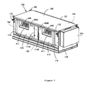
- a casing 100 includes a front plate 110, a back plate 120, a right side plate 130 to mount an electric component box 200 thereonto, a left side plate 140, a top plate 150, and a bottom plate 160.
- a discharge duct mounting frame 112 is mounted to the front plate 110 so as to integrally surround discharge openings 111A and 111B arranged so as to be spaced away from each other in a transverse direction.
- Hanging hooks 170 are attached to the front surface of the front plate 110 at both ends of the upper portion thereof.
- a pair of vertical rails 113 which is bent in an L shape so that the inner portions thereof face each other, are provided on both sides of each of the discharge openings 111A and 111B inwardly of the front plate.
- panel retainers 114 are attached inwardly to the lower end of portions of each of the discharge openings 111A and 111B.
- Each of the panel retainers 114 includes an inclined surface portion 114a that is slightly opened inwardly and a stopper portion 114b that has the shape of a frame to form a bottom.
- a suction duct mounting frame 122 is attached to the back plate 120 so as to surround a suction opening 121 through which a fin portion 301 of a heat exchanger 300 is exposed. Further, hanging hooks 170 are attached to the back plate 120 at both ends of the upper portion thereof (the lower portion in FIG. 3 showing the duct type air conditioner that is turned upside down).
- Fan units 400A and 400B have the same structure and are independent of each other to form a fan mechanism.
- each of the fan units 400A and 400B includes a fan panel 410, a motor support 420 mounted to the back surface of the fan panel 410, a DC motor 430 assembled with the motor support 420, a fan 440 that uses an output shaft of the DC motor 430 as a rotating shaft, a fan cover 450 that surrounds the fan 440 at portions other than where air is sucked and discharged, and a spacer 460 that is mounted on the motor support 420 to serve during the assembling and transport.
- a partition plate is used for two fans 410 directly fixed thereto while in the present invention such two separate fan panels (divided fan panel) instead of the single partition plate are used for the separate fans.
- Each of the fan panels 410 includes a discharge port 411 formed at a position facing the fan 440, a reinforcing plate 412 attached to the inside of the fan panel beside the discharge port 411 in the transverse direction, press portions 413 bent inwardly from upper portions of both side ends of the fan panel 410, and a handle portion 414 as a handle bent inwardly of an upper end portion of the fan panel except for both side ends of the upper end portion.
- the discharge ports 411 have a size small enough to be positioned in the range of the discharge openings 111A and 111B of the front plate 110.
- the reinforcing plate 412 is to reinforce a portion of the corresponding fan panel 410, and the motor support 420 is attached to said reinforcing plate 412.
- the motor support 420 is formed by bending a metal plate into a U shape.
- the motor support includes a spacer mounting surface 421 on which the spacer 460 is mounted, a bottom portion 422, and a side portion 423.
- Air holes 421a, 422a, and 423a are formed respectively in the spacer mounting surface 421, the bottom portion 422, and the side portion 423 so as not to interrupt airflow generated by the fan 440.
- mounting portions 421b, 422b, and 423c which are to be fixed to the fan panel 410, are formed by bending common end portions of the spacer mounting surface 421, the bottom portion 422, and the side portion 423 outward.
- reinforcing ribs are formed by bending the ends of the spacer mounting surface 421, the bottom portion 422, and the side portion 423 as well as the peripheries of the air holes.
- a substantially triangular pyramid-shaped protrusion 421d for positioning the spacer 460 is formed at the bent portion of the reinforcing rib 421c of the spacer mounting surface 421.
- the mounting portions 421b, 422b, and 423c are fixed on the reinforcing plate 412, which has already been attached to the inside of the fan panel 410 by screws 471. Accordingly, the motor support 420 is mounted on the inside of the fan panel 410 so as to protrude inwardly.
- the motor 430 is mounted on the motor support 420, a large deformation load is applied to the fan panel 410.
- the thickness of the portion of the fan panel 410 supporting the motor doubles with the reinforcing plate 412, the fan panel can sufficiently bear the load.
- the fan cover 450 is attached to the inside of the fan panel 410 by screws (not shown) so as not to interfere with the fan 440.
- a similar discharge port is formed in the fan cover 450 at a position corresponding to the discharge port 411 of the fan panel 410.
- the spacer 460 is formed by bending a metal plate into a U shape, and includes a top portion 461 and side portions 462 and 463 such that when the top plate 150 is mounted thereonto, the top portion 461 comes into abutment with said top plate.
- Air holes 462a and 463a are formed in both side portions 462 and 463 of the spacer 460 so as not to interrupt airflow generated by the fan 440.
- mounting portions 462b and 463b which are to be fixed to the spacer mounting surface 421 of the motor support 420, are formed by bending the lower ends of the both side portions 462 and 463 inwardly.
- a substantially triangular hole 463c is formed in the bent portion of the mounting portion 463b of the side portion 463 to give the spacer 460 the proper positions when the spacer 460 is to be mounted to the motor support 420.
- the spacer and the motor support are completely positioned by fitting the protrusion 421d for positioning the spacer mounting surface 421 of the motor support 420 into the hole 463c for positioning the spacer 460. Then, as shown in FIG. 6 , the mounting portions 462b and 463b of the spacer 460 are fixed to the spacer mounting surface 421 of the motor support 420 by screws 472.
- the respective fan units 400A and 400B are mounted inwardly of the front plate 110 by manually holding the handle portion 414 of the fan panels 410 and lowering said respective fan units from above so that the both edges of the fan panels are guided by the vertical rails 113 formed inwardly of the front plate 110 to face each other.
- each fan panel 410 rides the inclined surface portion 114a of the panel retainer 114 and slides forwardly while being guided downwardly to fit into the stopper portion 114b. Further, as shown in FIG. 7, the press portions 413, which are formed at both sides of the upper end of the fan panel 410, are pushed down into the vertical rails 113 such that the entire fan panel 410 is pressed against the front plate 110 provided forwardly thereof. Further, each of the fan panels 410 is fixed to the front plate 110 inwardly thereof by screws 473 such that the fan units 400A and 400B are assembled with the front plate 110. Therefore, as shown in FIGS. 1 and 2 , the discharge ports 411 of the fan units 400A and 400B and the fans 440, which are provided in the casing, are exposed to the outside through the discharge openings 111A and 111B.
- the fan mechanism requiring relatively heavy motors and formed of the fan units 400A and 400B that have the same structure are provided on two divided fan panels, respectively. Accordingly, the entire fan mechanism is downsized in comparison with a fan unit having the same air discharge performance with one motor and two fans, and the total weight of each of the fan units may thus be reduced by half. As a result, it is easier to handle and assemble the fan units. Further, a required die may be downsized such that initial investment can also be reduced. Furthermore, at the time of repair, the screws 473 used for a broken fan unit of the fan units 400A and 400B are removed and only a broken fan unit may be separated from the front plate 110 by manually holding the handle portion 414 with fingers to lift the broken fan unit. After the repair, it is also easy to perform a maintenance service.
- the fan units 400A and 400B are completely mounted on the inside of the front plate 110. Accordingly, it is easier to mount the fan units 400A and 400B on the inside of the front plate 110. Further, since the fan panel 410 is mounted at a regular position while being pressed against the inside of the front plate 110, screw holes of the front plate 110 naturally correspond to screw holes of the fan panels 410. As a result, screw insertion and tightening work is facilitated.
- the spacers 460 and the top plate 150 bear the impact loads. As a result, it may be possible to prevent the motor supports or the fan panels 410 from being deformed and to prevent deviation in the shafts of the motors 430 and the fans 440.
- the spacer 460 is mounted on the surface of the motor support 420 facing the bottom plate 160 because the spacer 460 supports the motor support 420 against the bottom plate 160.
- the heat exchange of the air sucked from the back plate 120 has been performed by the heat exchanger 300 through the operation of the fan units 400A and 400B and the air has then been discharged out of the front plate 110.
- the heat exchange of the air sucked from the front plate 110 may be performed by the heat exchanger 300 through the operation of the fan units 400A and 400B and the air may then be discharged out of the back plate 120.
- the discharge openings 111A and 111B serve as the suction opening 121 and the suction opening 121 serves as the discharge openings.
- the discharge duct mounting frame 112 serves as the suction duct mounting frame
- the suction duct mounting frame 122 serves as the discharge duct mounting frame.
Landscapes
- Engineering & Computer Science (AREA)
- Chemical & Material Sciences (AREA)
- Combustion & Propulsion (AREA)
- Mechanical Engineering (AREA)
- General Engineering & Computer Science (AREA)
- Devices For Blowing Cold Air, Devices For Blowing Warm Air, And Means For Preventing Water Condensation In Air Conditioning Units (AREA)
- Air Filters, Heat-Exchange Apparatuses, And Housings Of Air-Conditioning Units (AREA)
Abstract
The present invention solves a problem that the registration of screw holes for mounting fan panels on a front plate is practically solved.
A fan mechanism includes fan units having fan panels, motors mounted inwardly of said fan panels, and fans positioned inwardly of the fan panels and driven by the motors. A pair of vertical rails is mounted on both sides of each of discharge openings inwardly of the front plate so that the inner portions thereof face each other, and panel retainers are attached inwardly to the lower portions of the discharge openings. Press portions are formed at upper portions of both sides of the fan panels. Both sides of each fan panel are pushed down into the vertical rails downward from above while being guided by the pair of vertical rails, the lower edge of the fan panel rides on the panel retainer, and the press portions are pushed down into the vertical rails, so that the fan panel is pressed against the inside of the front plate.
Description
- The present invention relates to a duct type air conditioner of which an improvement of a fan mechanism is intended.
- As for a duct type air conditioner in the prior art, there is a technique to form a fan mechanism by assembling fans and motors with a fan panel, and the entire fan mechanism is received in a casing by mounting the fan panel inwardly of a front plate of a casing. Further, horizontal rails are provided on the upper and lower sides in the casing and said fan mechanism is withdrawn along the rails toward the left or right sides of the casing, so that maintenance is easily performed.
- When, however, the duct type air conditioner is installed in a building, ducts for distributing discharged drafts needed to be provided around the casing. In such a case, there used to be a case where it is difficult to withdraw the fan mechanism in a horizontal direction in some installation sites. It was once proposed that the upper rail is designed to be detachable such that the fan mechanism can be withdrawn in a vertical direction. In this arrangement, however, the entire fan mechanism is tilted inwardly in the casing by the weight of the motors of the fan mechanism. As a result, there is a problem that the registration of screw holes for mounting a fan panel to the front plate remarkably lost.
- An object of the present invention is to provide a duct type air conditioner that does not cause the above-mentioned problem by providing a mechanism for the controlled descent of the fan mechanism.
- In order to achieve the above object, according to a first embodiment of the invention, there is provided a duct type air conditioner including: a casing having discharge openings and a suction opening therein; said casing being composed of a front plate formed with a discharge duct mounting frame outwardly thereof so as to surround the discharge openings; a fan mechanism mounted inwardly of said front plate; said casing being further composed of a back plate formed with a suction duct mounting frame outwardly thereof so as to surround said suction opening; and a heat exchanger mounted inwardly of said back plate. The fan mechanism includes fan units having fan panels, motors mounted inwardly of said fan panels, and fans positioned inwardly of the fan panels and driven by the motors. A pair of L-shaped vertical rails is mounted on both sides of each of the discharge openings inwardly of the front plate so that the inner portions thereof face each other, and panel retainers are attached inwardly to the lower portions of the discharge openings. Press portions are formed at upper portions of both sides of the fan panels. Both edges of each fan panel are inserted into the vertical rails downward from above while being guided by the pair of vertical rails, the lower edge of the fan panel rides on the panel retainer, and the press portions of the fan panel are pushed down into the vertical rails, so that the fan panel is pressed against the inside of the front plate.
According to a second embodiment of the invention, in the duct type air conditioner according to the first embodiment of the invention, the press portions are formed by bending upper portions of the both edges of the fan panels inwardly.
According to a third embodiment of the invention, in the duct type air conditioner according to the first or second embodiment of the invention, each of the panel retainers includes an inclined surface portion opening inwardly and a stopper portion having a shape to form a bottom. When the both edges of each fan panel are inserted into the vertical rails downward from above while being guided by the pair of vertical rails, the lower edge of the fan panel is guided downwardly and fitted into the stopper portion down the inclined surface portion of the panel retainer.
According to a fourth embodiment of the invention, in the duct type air conditioner according to any one of the first to third embodiments of the invention, a handle portion, which is bent inward, is formed at an upper end of each of the fan panels.
According to a fifth embodiment of the invention, in the duct type air conditioner according to any one of the first to fourth embodiments of the invention, the discharge openings are substituted by the suction opening, the suction opening is substituted by the discharge openings, the discharge duct mounting frame is substituted by the suction duct mounting frame, and the suction duct mounting frame is substituted by the discharge duct mounting frame. - According to the embodiments of the invention, when lower edges of fan panels are inserted until coming into contact with panel retainers while the fan panels are guided by vertical rails from the upper side of the vertical rails mounted on both sides of a front plate and pressing pieces of the fan panels are then inserted into the vertical rails, fan units as a fan mechanism are completely mounted on the inside of the front plate. Accordingly, it is easy to mount the fan units on the inside of the front plate. Further, since the fan panel is mounted at a regular position while being pressed against the inside of the front plate, screw holes of the front plate naturally correspond to screw holes of the fan panels. As a result, it is easy to insert and tighten screws.
-
-
FIG. 1 is a perspective view of a duct type air conditioner according to an embodiment of the invention; -
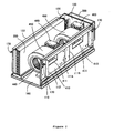
FIG. 2 is a perspective view of the duct type air conditioner from which a top plate and a left side plate are removed; -
FIG. 3 is a partial perspective view of the duct type air conditioner from which a right side plate and an electric component box are removed and which is turned upside down; -
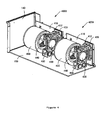
FIG. 4 is a perspective view of fan units provided in the duct type air conditioner and turned upside down; -
FIG. 5 is an exploded perspective view showing that the fan units are assembled with a front plate of the duct type air conditioner; -
FIG. 6 is an exploded perspective view showing that a spacer is assembled with a motor supporting frame of the duct type air conditioner; and - FIG. 7 is a view illustrating a mechanism for maintaining the posture of a fan panel of the duct type air conditioner.
- In
FIG. 1 , acasing 100 includes afront plate 110, aback plate 120, aright side plate 130 to mount anelectric component box 200 thereonto, aleft side plate 140, atop plate 150, and abottom plate 160. - For example, as shown in
FIG. 5 , a dischargeduct mounting frame 112 is mounted to thefront plate 110 so as to integrally surrounddischarge openings front plate 110 at both ends of the upper portion thereof. Further, a pair ofvertical rails 113, which is bent in an L shape so that the inner portions thereof face each other, are provided on both sides of each of thedischarge openings panel retainers 114 are attached inwardly to the lower end of portions of each of thedischarge openings panel retainers 114 includes aninclined surface portion 114a that is slightly opened inwardly and astopper portion 114b that has the shape of a frame to form a bottom. - For example, as shown in
FIG. 3 showing the duct type air conditioner turned upside down, a suctionduct mounting frame 122 is attached to theback plate 120 so as to surround asuction opening 121 through which afin portion 301 of aheat exchanger 300 is exposed. Further, hanginghooks 170 are attached to theback plate 120 at both ends of the upper portion thereof (the lower portion inFIG. 3 showing the duct type air conditioner that is turned upside down). -
Fan units FIGS. 2 to 5 , each of thefan units fan panel 410, amotor support 420 mounted to the back surface of thefan panel 410, aDC motor 430 assembled with themotor support 420, afan 440 that uses an output shaft of theDC motor 430 as a rotating shaft, afan cover 450 that surrounds thefan 440 at portions other than where air is sucked and discharged, and aspacer 460 that is mounted on themotor support 420 to serve during the assembling and transport. - In the prior art, a partition plate is used for two
fans 410 directly fixed thereto while in the present invention such two separate fan panels (divided fan panel) instead of the single partition plate are used for the separate fans. Each of thefan panels 410 includes adischarge port 411 formed at a position facing thefan 440, a reinforcingplate 412 attached to the inside of the fan panel beside thedischarge port 411 in the transverse direction,press portions 413 bent inwardly from upper portions of both side ends of thefan panel 410, and ahandle portion 414 as a handle bent inwardly of an upper end portion of the fan panel except for both side ends of the upper end portion. Thedischarge ports 411 have a size small enough to be positioned in the range of thedischarge openings front plate 110. The reinforcingplate 412 is to reinforce a portion of thecorresponding fan panel 410, and themotor support 420 is attached to said reinforcingplate 412. - As shown in
FIG. 6 , themotor support 420 is formed by bending a metal plate into a U shape. The motor support includes aspacer mounting surface 421 on which thespacer 460 is mounted, abottom portion 422, and aside portion 423.Air holes spacer mounting surface 421, thebottom portion 422, and theside portion 423 so as not to interrupt airflow generated by thefan 440. A mountinghole 423b, in order to mount themotor 430 therethrough, is formed in theside portion 423. In addition, mountingportions fan panel 410, are formed by bending common end portions of thespacer mounting surface 421, thebottom portion 422, and theside portion 423 outward. Further, reinforcing ribs are formed by bending the ends of thespacer mounting surface 421, thebottom portion 422, and theside portion 423 as well as the peripheries of the air holes. Furthermore, a substantially triangular pyramid-shapedprotrusion 421d for positioning thespacer 460 is formed at the bent portion of the reinforcingrib 421c of thespacer mounting surface 421. - In order to mount the
motor support 420 to the inside of thefan panel 410, the mountingportions plate 412, which has already been attached to the inside of thefan panel 410 byscrews 471. Accordingly, themotor support 420 is mounted on the inside of thefan panel 410 so as to protrude inwardly. When themotor 430 is mounted on themotor support 420, a large deformation load is applied to thefan panel 410. However, since the thickness of the portion of thefan panel 410 supporting the motor doubles with the reinforcingplate 412, the fan panel can sufficiently bear the load. - The
fan cover 450 is attached to the inside of thefan panel 410 by screws (not shown) so as not to interfere with thefan 440. A similar discharge port is formed in thefan cover 450 at a position corresponding to thedischarge port 411 of thefan panel 410. - As shown in
FIG. 6 , thespacer 460 is formed by bending a metal plate into a U shape, and includes atop portion 461 andside portions top plate 150 is mounted thereonto, thetop portion 461 comes into abutment with said top plate.Air holes side portions spacer 460 so as not to interrupt airflow generated by thefan 440. Further, mountingportions spacer mounting surface 421 of themotor support 420, are formed by bending the lower ends of the bothside portions triangular hole 463c is formed in the bent portion of the mountingportion 463b of theside portion 463 to give thespacer 460 the proper positions when thespacer 460 is to be mounted to themotor support 420. - In order to mount the
spacer 460 to themotor support 420, the spacer and the motor support are completely positioned by fitting theprotrusion 421d for positioning thespacer mounting surface 421 of themotor support 420 into thehole 463c for positioning thespacer 460. Then, as shown inFIG. 6 , the mountingportions spacer 460 are fixed to thespacer mounting surface 421 of themotor support 420 byscrews 472. - As shown in
FIG. 5 , after being separately assembled in advance, therespective fan units front plate 110 by manually holding thehandle portion 414 of thefan panels 410 and lowering said respective fan units from above so that the both edges of the fan panels are guided by thevertical rails 113 formed inwardly of thefront plate 110 to face each other. - In this case, the lower edge of each
fan panel 410 rides theinclined surface portion 114a of thepanel retainer 114 and slides forwardly while being guided downwardly to fit into thestopper portion 114b. Further, as shown in FIG. 7, thepress portions 413, which are formed at both sides of the upper end of thefan panel 410, are pushed down into thevertical rails 113 such that theentire fan panel 410 is pressed against thefront plate 110 provided forwardly thereof. Further, each of thefan panels 410 is fixed to thefront plate 110 inwardly thereof byscrews 473 such that thefan units front plate 110. Therefore, as shown inFIGS. 1 and2 , thedischarge ports 411 of thefan units fans 440, which are provided in the casing, are exposed to the outside through thedischarge openings - As described above, the fan mechanism requiring relatively heavy motors and formed of the
fan units screws 473 used for a broken fan unit of thefan units front plate 110 by manually holding thehandle portion 414 with fingers to lift the broken fan unit. After the repair, it is also easy to perform a maintenance service. - In addition, when the lower edges of the
fan panels 410 of thefan units panel retainers 114 while the fan panels are guided by thevertical rails 113 from the upper side thereof formed on both sides of thefront plate 110 and thepress portion 413 of thefan panels 410 are then pushed down into thevertical rails 113, thefan units front plate 110. Accordingly, it is easier to mount thefan units front plate 110. Further, since thefan panel 410 is mounted at a regular position while being pressed against the inside of thefront plate 110, screw holes of thefront plate 110 naturally correspond to screw holes of thefan panels 410. As a result, screw insertion and tightening work is facilitated. - Further, there are times when the duct type air conditioner is needed to be turned upside down at the time of assembling or conveyance after completion of the assembling operation. If, however, a drop accident occurs due to a certain cause when the duct type air conditioner is turned upside down, large impact loads are applied to the
fan panels 410 by the weight of themotors 430 of thefan units fan panels 410 being deformed to cause deviation to occur in the shafts of themotors 430 and thefans 440. In this embodiment, since thespacers 460 are mounted on thespacer mounting surfaces 421 of the motor supports 420, thespacers 460 are interposed between thetop plate 150 and the motor supports 420 as shown inFIG. 4 . Accordingly, thespacers 460 and thetop plate 150 bear the impact loads. As a result, it may be possible to prevent the motor supports or thefan panels 410 from being deformed and to prevent deviation in the shafts of themotors 430 and thefans 440. - Meanwhile, in the case the
bottom plate 160 is to maintain the lower position by serving as a bottom even at the time of conveyance as at the time of installation, the motor and the fan are likewise completely protected even in a drop accident thespacer 460 is mounted on the surface of themotor support 420 facing thebottom plate 160 because thespacer 460 supports themotor support 420 against thebottom plate 160. - Further, in the above-mentioned embodiments, the heat exchange of the air sucked from the
back plate 120 has been performed by theheat exchanger 300 through the operation of thefan units front plate 110. However, the heat exchange of the air sucked from thefront plate 110 may be performed by theheat exchanger 300 through the operation of thefan units back plate 120. In this case, thedischarge openings suction opening 121 and thesuction opening 121 serves as the discharge openings. Further, the dischargeduct mounting frame 112 serves as the suction duct mounting frame, and the suctionduct mounting frame 122 serves as the discharge duct mounting frame.
Claims (5)
- A duct type air conditioner comprising at least: a casing having discharge openings and a suction opening therein; said casing being composed of a front plate formed with a discharge duct mounting frame outwardly thereof so as to surround the discharge openings; a fan mechanism mounted inwardly of said front plate; said casing being further composed of a back plate formed with a suction duct mounting frame outwardly thereof so as to surround said suction opening; and a heat exchanger mounted inwardly of said back plate,
wherein said fan mechanism includes fan units having fan panels, motors mounted inwardly of said fan panels, and fans positioned inwardly of the fan panels and driven by the motors,
a pair of L-shaped vertical rails is mounted on both sides of each of the discharge openings inwardly of the front plate so that the inner portions thereof face each other, and panel retainers are attached inwardly to the lower end portions of the discharge openings,
press portions are formed at upper portions of both sides of the fan panels, and
both edges of each fan panel are inserted into the vertical rails downward from above while being guided by the pair of vertical rails, the lower edge of the fan panel rides the panel retainer, and the press portions of the fan panel are pushed down into the vertical rails, so that the fan panel is pressed against the inside of the front plate. - The duct type air conditioner according to claim 1,
wherein the press portions are formed by bending upper portions of the both edges of the fan panels inwardly. - The duct type air conditioner according to claim 1 or 2,
wherein each of the panel retainers comprises an inclined surface portion opening inwardly and a stopper portion having a shape of a frame to form a bottom, and
when the both edges of each fan panel are inserted into the vertical rails downward from above while being guided by the pair of vertical rails, the lower edge of the fan panel is guided downwardly and fitted into the stopper portion down the inclined surface portion of the panel retainer. - The duct type air conditioner according to any one of claims 1 to 3,
wherein a handle portion, which is bent inwardly, is formed at an upper end of each of the fan panels. - The duct type air conditioner according to any one of claims 1 to 4,
wherein the discharge openings are substituted by the suction opening, the suction opening is substituted by the discharge openings, the discharge duct mounting frame is substituted by the suction duct mounting frame, and the suction duct mounting frame is substituted by the discharge duct mounting frame.
Applications Claiming Priority (1)
| Application Number | Priority Date | Filing Date | Title |
|---|---|---|---|
| JP2009281457A JP5565664B2 (en) | 2009-12-11 | 2009-12-11 | Duct type air conditioner |
Publications (1)
| Publication Number | Publication Date |
|---|---|
| EP2336654A2 true EP2336654A2 (en) | 2011-06-22 |
Family
ID=43735925
Family Applications (1)
| Application Number | Title | Priority Date | Filing Date |
|---|---|---|---|
| EP10168891A Withdrawn EP2336654A2 (en) | 2009-12-11 | 2010-07-08 | Duct Type Air Conditioner |
Country Status (5)
| Country | Link |
|---|---|
| US (1) | US9506661B2 (en) |
| EP (1) | EP2336654A2 (en) |
| JP (1) | JP5565664B2 (en) |
| CN (1) | CN102095224B (en) |
| AU (1) | AU2010212428B2 (en) |
Cited By (2)
| Publication number | Priority date | Publication date | Assignee | Title |
|---|---|---|---|---|
| EP2944759A1 (en) * | 2014-05-14 | 2015-11-18 | Ingersoll-Rand Company | Air compressor system |
| EP3252385A4 (en) * | 2015-01-29 | 2018-08-29 | Mitsubishi Electric Corporation | Air conditioner |
Families Citing this family (11)
| Publication number | Priority date | Publication date | Assignee | Title |
|---|---|---|---|---|
| CN102679453B (en) * | 2012-05-18 | 2016-12-14 | 海尔集团公司 | Air-conditioner |
| USD725249S1 (en) * | 2013-03-15 | 2015-03-24 | TSI Products, Inc. | Blower assembly |
| USD725250S1 (en) * | 2013-03-15 | 2015-03-24 | TSI Products, Inc. | Blower assembly |
| USD769435S1 (en) * | 2014-12-03 | 2016-10-18 | Ignis Development Inc | Double-sided ethanol fireplace insert |
| USD770606S1 (en) * | 2014-12-03 | 2016-11-01 | Ignis Development Inc | Single-sided ethanol fireplace insert |
| JP6456483B2 (en) * | 2015-04-17 | 2019-01-23 | 三菱電機株式会社 | Air conditioner indoor unit |
| KR102341728B1 (en) * | 2017-03-21 | 2021-12-22 | 삼성전자주식회사 | Air conditioner |
| US11885511B2 (en) * | 2019-04-22 | 2024-01-30 | Q-Pac Systems, Inc. | Modular bulkhead system |
| CN116348713A (en) * | 2020-11-11 | 2023-06-27 | 三星电子株式会社 | air conditioner |
| CN112594913A (en) * | 2020-12-30 | 2021-04-02 | 佛山市顺德区美的电子科技有限公司 | Shell plate assembly for air conditioner and air conditioner with shell plate assembly |
| US12529485B2 (en) * | 2023-01-09 | 2026-01-20 | Tyco Fire & Security Gmbh | Fan assembly for HVAC system |
Family Cites Families (24)
| Publication number | Priority date | Publication date | Assignee | Title |
|---|---|---|---|---|
| US4130376A (en) * | 1977-06-23 | 1978-12-19 | Westinghouse Electric Corp. | Fan mounting arrangement |
| US4449376A (en) * | 1983-02-18 | 1984-05-22 | Westinghouse Electric Corp. | Indoor unit for electric heat pump |
| JPS6129223U (en) * | 1984-07-26 | 1986-02-21 | ダイキン工業株式会社 | ceiling air conditioner |
| JPH0448464Y2 (en) * | 1986-01-31 | 1992-11-16 | ||
| JPS62299637A (en) * | 1986-06-19 | 1987-12-26 | Matsushita Seiko Co Ltd | Ceiling recessed type air conditioner |
| JPH0347154Y2 (en) * | 1986-10-31 | 1991-10-07 | ||
| JPH046341A (en) * | 1990-04-24 | 1992-01-10 | Mitsubishi Electric Corp | Air conditioner |
| US6082131A (en) * | 1998-10-20 | 2000-07-04 | Hoshizaki Denki Co., Ltd. | Refrigerator |
| KR100293708B1 (en) * | 1998-11-26 | 2001-11-26 | 구자홍 | Vibration Absorption Device for Ceiling Duct Air Conditioner |
| JP2001227770A (en) * | 2000-02-18 | 2001-08-24 | Fujitsu General Ltd | Air conditioner |
| JP2001227768A (en) * | 2000-02-18 | 2001-08-24 | Fujitsu General Ltd | Air conditioner |
| JP3088338U (en) * | 2002-03-05 | 2002-09-06 | サンシェード工業株式会社 | Movable shading plate screen |
| KR20050064963A (en) * | 2003-12-24 | 2005-06-29 | 엘지전자 주식회사 | The supporting structure of pipe for duct type air-conditioner |
| US6997005B2 (en) * | 2004-03-12 | 2006-02-14 | Omniteam Inc. | Efficient cooling system |
| CN1712852A (en) * | 2004-06-21 | 2005-12-28 | 乐金电子(天津)电器有限公司 | Housing integrating structure of pipeline air conditioner |
| KR100629342B1 (en) * | 2005-01-27 | 2006-09-29 | 엘지전자 주식회사 | Air conditioner |
| WO2006080793A2 (en) * | 2005-01-27 | 2006-08-03 | Lg Electronics, Inc. | Indoor unit of air conditioner |
| JP2007056681A (en) * | 2005-08-22 | 2007-03-08 | Funai Electric Co Ltd | Fan holder structure |
| CN2883995Y (en) * | 2005-09-19 | 2007-03-28 | 松下电器产业株式会社 | A ducted air conditioner |
| US8056933B2 (en) * | 2006-04-07 | 2011-11-15 | Dometic Corporation | Quick connect flange plate |
| JP4905014B2 (en) * | 2006-09-20 | 2012-03-28 | 株式会社富士通ゼネラル | Air conditioner |
| US8096137B2 (en) * | 2007-10-01 | 2012-01-17 | Hoshizaki America, Inc. | Systems and methods for guiding and supporting an evaporator structure |
| CN101498470A (en) * | 2008-01-31 | 2009-08-05 | 乐金电子(天津)电器有限公司 | Indoor unit of pipe type air conditioner |
| KR101537589B1 (en) * | 2008-05-01 | 2015-07-17 | 엘지전자 주식회사 | Duct type air conditioner |
-
2009
- 2009-12-11 JP JP2009281457A patent/JP5565664B2/en not_active Expired - Fee Related
-
2010
- 2010-07-08 EP EP10168891A patent/EP2336654A2/en not_active Withdrawn
- 2010-08-18 AU AU2010212428A patent/AU2010212428B2/en active Active
- 2010-08-26 CN CN201010265957.0A patent/CN102095224B/en active Active
- 2010-10-12 US US12/902,187 patent/US9506661B2/en active Active
Non-Patent Citations (1)
| Title |
|---|
| None |
Cited By (3)
| Publication number | Priority date | Publication date | Assignee | Title |
|---|---|---|---|---|
| EP2944759A1 (en) * | 2014-05-14 | 2015-11-18 | Ingersoll-Rand Company | Air compressor system |
| US10047766B2 (en) | 2014-05-14 | 2018-08-14 | Ingersoll-Rand Company | Air compressor system |
| EP3252385A4 (en) * | 2015-01-29 | 2018-08-29 | Mitsubishi Electric Corporation | Air conditioner |
Also Published As
| Publication number | Publication date |
|---|---|
| US9506661B2 (en) | 2016-11-29 |
| US20110138844A1 (en) | 2011-06-16 |
| CN102095224B (en) | 2015-08-19 |
| CN102095224A (en) | 2011-06-15 |
| JP2011122781A (en) | 2011-06-23 |
| AU2010212428A1 (en) | 2011-06-30 |
| AU2010212428B2 (en) | 2016-02-04 |
| JP5565664B2 (en) | 2014-08-06 |
Similar Documents
| Publication | Publication Date | Title |
|---|---|---|
| US9506661B2 (en) | Duct type air conditioner | |
| EP2336655A2 (en) | Duct Type Air Conditioner | |
| EP2336656A2 (en) | Duct type air conditioner | |
| CN104344472B (en) | The outdoor unit of air conditioner | |
| EP3169942B1 (en) | Duct type air conditioning device and method for assembling and disassembling the same | |
| CN104520649B (en) | Outdoor unit of refrigeration cycle plant | |
| EP3217107A1 (en) | Outdoor unit of air conditioner | |
| WO2021111618A1 (en) | Outdoor unit for air conditioner | |
| JP2010286228A (en) | Heat exchange device and heating element storage device using the same | |
| US20220128247A1 (en) | Outdoor unit of air-conditioning apparatus | |
| EP1453367A2 (en) | Control box | |
| JPWO2016103447A1 (en) | Outdoor unit | |
| JP6323203B2 (en) | Duct type air conditioner | |
| TWI516679B (en) | Fan with installing structure and fan structure thereof | |
| CN219141024U (en) | air handling unit | |
| JP6984162B2 (en) | Outdoor unit of air conditioner | |
| US20240167700A1 (en) | Modular Bulkhead System | |
| JP2586742B2 (en) | Air conditioner blower mounting structure | |
| JP2009085440A (en) | Air conditioner outdoor unit | |
| WO2020170329A1 (en) | Air-conditioner outdoor unit | |
| KR20040067719A (en) | Structure combining front upper panel with inlet grill for airconditioner |
Legal Events
| Date | Code | Title | Description |
|---|---|---|---|
| PUAI | Public reference made under article 153(3) epc to a published international application that has entered the european phase |
Free format text: ORIGINAL CODE: 0009012 |
|
| AK | Designated contracting states |
Kind code of ref document: A2 Designated state(s): AL AT BE BG CH CY CZ DE DK EE ES FI FR GB GR HR HU IE IS IT LI LT LU LV MC MK MT NL NO PL PT RO SE SI SK SM TR |
|
| AX | Request for extension of the european patent |
Extension state: BA ME RS |
|
| STAA | Information on the status of an ep patent application or granted ep patent |
Free format text: STATUS: THE APPLICATION IS DEEMED TO BE WITHDRAWN |
|
| 18D | Application deemed to be withdrawn |
Effective date: 20130201 |