EP2336591A1 - Electric motor with passive integral brake - Google Patents
Electric motor with passive integral brake Download PDFInfo
- Publication number
- EP2336591A1 EP2336591A1 EP10252120A EP10252120A EP2336591A1 EP 2336591 A1 EP2336591 A1 EP 2336591A1 EP 10252120 A EP10252120 A EP 10252120A EP 10252120 A EP10252120 A EP 10252120A EP 2336591 A1 EP2336591 A1 EP 2336591A1
- Authority
- EP
- European Patent Office
- Prior art keywords
- brake shoe
- brake
- electric motor
- rotor shaft
- magnetic field
- Prior art date
- Legal status (The legal status is an assumption and is not a legal conclusion. Google has not performed a legal analysis and makes no representation as to the accuracy of the status listed.)
- Withdrawn
Links
Images

Classifications
-
- F—MECHANICAL ENGINEERING; LIGHTING; HEATING; WEAPONS; BLASTING
- F16—ENGINEERING ELEMENTS AND UNITS; GENERAL MEASURES FOR PRODUCING AND MAINTAINING EFFECTIVE FUNCTIONING OF MACHINES OR INSTALLATIONS; THERMAL INSULATION IN GENERAL
- F16D—COUPLINGS FOR TRANSMITTING ROTATION; CLUTCHES; BRAKES
- F16D49/00—Brakes with a braking member co-operating with the periphery of a drum, wheel-rim, or the like
- F16D49/16—Brakes with two brake-blocks
-
- H—ELECTRICITY
- H02—GENERATION; CONVERSION OR DISTRIBUTION OF ELECTRIC POWER
- H02K—DYNAMO-ELECTRIC MACHINES
- H02K7/00—Arrangements for handling mechanical energy structurally associated with dynamo-electric machines, e.g. structural association with mechanical driving motors or auxiliary dynamo-electric machines
- H02K7/10—Structural association with clutches, brakes, gears, pulleys or mechanical starters
- H02K7/102—Structural association with clutches, brakes, gears, pulleys or mechanical starters with friction brakes
- H02K7/1021—Magnetically influenced friction brakes
- H02K7/1026—Magnetically influenced friction brakes using stray fields
-
- F—MECHANICAL ENGINEERING; LIGHTING; HEATING; WEAPONS; BLASTING
- F16—ENGINEERING ELEMENTS AND UNITS; GENERAL MEASURES FOR PRODUCING AND MAINTAINING EFFECTIVE FUNCTIONING OF MACHINES OR INSTALLATIONS; THERMAL INSULATION IN GENERAL
- F16D—COUPLINGS FOR TRANSMITTING ROTATION; CLUTCHES; BRAKES
- F16D2121/00—Type of actuator operation force
- F16D2121/18—Electric or magnetic
- F16D2121/20—Electric or magnetic using electromagnets
- F16D2121/22—Electric or magnetic using electromagnets for releasing a normally applied brake
Definitions
- the subject matter disclosed herein generally relates to electro-mechanical systems, and more particularly to an electric motor with a passive integral brake.
- Certain applications for electro-mechanical actuators require that an electro-mechanical actuator hold a load in a stationary position after electrical power to operate the electro-mechanical actuator has been removed.
- One approach to holding a stationary position absent electrical power is the use of a friction device that drags at all times. Examples of friction devices include friction pads, ball ramps, heavily pre-loaded rolling element bearings, and skewed roller bearings. The ever-present drag produced by these friction devices typically requires over sizing of the drive motor and reduces actuator efficiency.
- an actively controlled brake can alleviate the inefficiency associated with a continuously dragging brake; however, the actively controlled brake adds complexity by requiring a control system for operation. Some actively controlled brakes use electrical power to engage the brake, while others use additional electrical power to release the brake. The inclusion of an actively controlled brake in an electro-mechanical actuation system also increases the overall size and weight of the system, and may demand additional electrical power to set and release the actively controlled brake.
- an electric motor with passive integral brake includes a stator with one or more magnetic field controllable coils and a rotor with a rotor shaft positioned within an inner diameter of the stator.
- the rotor is operable to rotate about a longitudinal axis of the rotor shaft.
- the electric motor with passive integral brake also includes a brake shoe positioned within the inner diameter of the stator along the longitudinal axis of the rotor shaft. The brake shoe is operable to apply a braking force to the rotor shaft and remove the braking force from the rotor shaft responsive to a magnetic field strength produced by the one or more magnetic field controllable coils.
- an electro-mechanical system includes a mechanical actuator, a gear train coupled to the mechanical actuator, and an electric motor with passive integral brake coupled to the gear train.
- the electric motor operably provides a mechanical force through the gear train to apply and stop mechanical movement of the mechanical actuator, where the passive integral brake is positioned within the electric motor and is magnetically controlled.
- a method for producing passive integral braking in an electric motor includes positioning a rotor with a rotor shaft within an inner diameter of a stator.
- the stator includes one or more magnetic field controllable coils.
- the rotor is operable to rotate about a longitudinal axis of the rotor shaft.
- the method further includes positioning a brake shoe within the inner diameter of the stator along the longitudinal axis of the rotor shaft.
- the method also includes applying a braking force between the brake shoe and the rotor shaft responsive to a magnetic field strength produced by the one or more magnetic field controllable coils being below a threshold value.
- the method additionally includes removing the braking force between the brake shoe and the rotor shaft responsive to the magnetic field strength being above the threshold value.
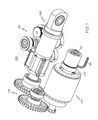
- FIG. 1 illustrates an exemplary embodiment of an electro-mechanical system including an electric motor with passive integral brake
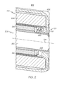
- FIG. 2 is side cutaway view of the electric motor with passive integral brake of FIG. 1 ;
- FIG. 3 is front cutaway view of the electric motor with passive integral brake of FIGS. 1 and 2 .
- the invention as described in greater detail herein provides a passive, spring set, brake that is integrated into an electric motor assembly.
- the electric motor assembly may be integrated with a mechanical actuator to form an electro-mechanical actuator with a passive integral brake.
- the passive integral brake prohibits rotation of a rotor in the electric motor when electrical power is removed from the electric motor.
- FIG. 1 illustrates an exemplary embodiment of an electro-mechanical system 100 including an electric motor 102 with passive integral brake 104.
- the electro-mechanical system 100 also includes a mechanical actuator 106 and a gear train 108 coupled to the mechanical actuator 106.
- the electro-mechanical system 100 may further include a position feedback apparatus 110 to enable closed-loop control of the mechanical actuator 106.
- the electric motor 102 is also coupled to the gear train 108, operably providing a mechanical force through the gear train 108 to apply and stop mechanical movement of the mechanical actuator 106.
- the passive integral brake 104 is positioned within the electric motor 102 and is magnetically controlled.
- a resolver 112 can be used to provide motor position feedback and control commutation in the electric motor 102 through electrical connector 114.
- the electro-mechanical system 100 may be packaged in a housing to form an integrated electro-mechanical actuator capable of holding a load in a stationary position after electrical power to operate the electro-mechanical actuator has been removed.
- FIG. 2 is side cutaway view of the electric motor 102 with passive integral brake 104 of FIG. 1 .
- the electric motor 102 includes a stator 204 with one or more magnetic field controllable coils 206.
- the electric motor 102 also includes a rotor 208 with a rotor shaft 210 positioned within an inner diameter 212 of the stator 204.
- the rotor 208 is operable to rotate about a longitudinal axis 214 of the rotor shaft 210.
- the rotor may also include a permanent magnet 216 to interact with a magnetic field produced by the one or more magnetic field controllable coils 206, resulting in the rotor shaft 210 rotating about the longitudinal axis 214.
- the passive integral brake 104 includes one or more brake shoes 218 positioned within the inner diameter 212 of the stator 204 along the longitudinal axis 214 of the rotor shaft 210.
- the one or more brake shoes 218 are operable to apply a braking force to the rotor shaft 210 and remove the braking force from the rotor shaft 210 responsive to a magnetic field strength produced by the one or more magnetic field controllable coils 206.
- One or more springs 220 coupled to the one or more brake shoes 218 passively apply the braking force between the one or more brake shoes 218 and the rotor shaft 210 absent the magnetic field strength exceeding a threshold level to attract the one or more brake shoes 218 to the inner diameter 212 of the stator 204.
- the one or more brake shoes 218 are coupled to one or more pivots 222 to control movement of the one or more brake shoes 218.
- the compressive force of the one or more springs 220 is overcome, and the one or more brake shoes 218 rotate about the one or more pivots 222 toward the inner diameter 212 of the stator 204, thereby releasing the braking force from the rotor shaft 210.
- the compressive force of the one or more springs 220 exceeds the magnetic force between the one or more brake shoes 218 and the one or more magnetic field controllable coils 206, resulting in the one or more brake shoes 218 rotating about the one or more pivots 222 towards the rotor shaft 210 and applying the braking force.
- the one or more brake shoes 218 are each constructed of a plurality of laminated ferromagnetic layers. Using laminated ferromagnetic layers, such as steal laminations, rather than solid body construction may better mitigate heating issues to prevent overheating of the one or more brake shoes 218.
- the ferromagnetic material in the one or more brake shoes 218 enables the one or more brake shoes 218 to be magnetically attracted to the magnetic field produced by the one or more magnetic field controllable coils 206.
- the one or more springs 220 are non-ferromagnetic to prevent the one or more springs 220 from being attracted to the one or more magnetic field controllable coils 206.
- FIG. 3 is front cutaway view of the electric motor 102 with passive integral brake 104 of FIGS. 1 and 2 .
- FIG. 3 again illustrates the stator 204 with one or more magnetic field controllable coils 206 within the motor assembly housing 202.
- FIG. 3 also depicts the rotor shaft 210 positioned within the inner diameter 212 of the stator 204, and the one or more brake shoes 218 coupled to one or more springs 220 and one or more pivots 222.
- the one or more brake shoes 218 are depicted as a first brake shoe 302 and a second brake shoe 304. Friction material 306 and 308 on the first and second brake shoes 302 and 304 apply the braking force to the rotor shaft 210 when the one or more springs 220 are compressed.
- the one or more brake shoes 218 are positioned at a location along the longitudinal axis of the rotor shaft which is displaced from the location of the permanent magnet 216.
- the brake shoes(s) 218 are disposed generally circumferentially around the rotor shaft 210.
- the braking force can be passively applied between the first and second brake shoes 302 and 304 and the rotor shaft 210 responsive to the magnetic field strength produced by the one or more magnetic field controllable coils 206 being below a threshold value.
- the braking force between the first and second brake shoes 302 and 304 and the rotor shaft 210 can be removed responsive to the magnetic field strength being above the threshold value, as the one or more brake shoes 218 are attracted to the inner diameter 212 of the stator 206.
- FIG. 3 depicts the first and second brake shoes 302 and 304 with two separate pivots 222 and coupled by two springs 220
- a single brake shoe 302 or 304 can be coupled to a single spring 220, where the single spring 220 is anchored to the stator 206.
- the first and second brake shoes 302 and 304 can be coupled to a single pivot 222.
- Multiple instances of the passive integral brake 104 can be included within the electric motor 102 for redundancy, staged braking, and/or load distribution.
Landscapes
- Engineering & Computer Science (AREA)
- General Engineering & Computer Science (AREA)
- Mechanical Engineering (AREA)
- Power Engineering (AREA)
- Connection Of Motors, Electrical Generators, Mechanical Devices, And The Like (AREA)
Abstract
An electric motor (102) with passive integral brake (104) includes a stator (204) with one or more magnetic field controllable coils (206) and a rotor (208) with a rotor shaft (210) positioned within an inner diameter (212) of the stator (204). The rotor (208) is operable to rotate about a longitudinal axis (214) of the rotor shaft (210). The electric motor (102) with passive integral brake (104) also includes a brake shoe (302) positioned within the inner diameter (212) of the stator (204) along the longitudinal axis (214) of the rotor shaft (210). The brake shoe (302) is operable to apply a braking force to the rotor shaft (210) and remove the braking force from the rotor shaft (210) responsive to a magnetic field strength produced by the one or more magnetic field controllable coils (206). One or more springs (220) passively apply the braking force.
Description
- The subject matter disclosed herein generally relates to electro-mechanical systems, and more particularly to an electric motor with a passive integral brake.
- Certain applications for electro-mechanical actuators require that an electro-mechanical actuator hold a load in a stationary position after electrical power to operate the electro-mechanical actuator has been removed. One approach to holding a stationary position absent electrical power is the use of a friction device that drags at all times. Examples of friction devices include friction pads, ball ramps, heavily pre-loaded rolling element bearings, and skewed roller bearings. The ever-present drag produced by these friction devices typically requires over sizing of the drive motor and reduces actuator efficiency.
- Using an actively controlled brake can alleviate the inefficiency associated with a continuously dragging brake; however, the actively controlled brake adds complexity by requiring a control system for operation. Some actively controlled brakes use electrical power to engage the brake, while others use additional electrical power to release the brake. The inclusion of an actively controlled brake in an electro-mechanical actuation system also increases the overall size and weight of the system, and may demand additional electrical power to set and release the actively controlled brake.
- According to one aspect of the invention, an electric motor with passive integral brake is provided. The electric motor with passive integral brake includes a stator with one or more magnetic field controllable coils and a rotor with a rotor shaft positioned within an inner diameter of the stator. The rotor is operable to rotate about a longitudinal axis of the rotor shaft. The electric motor with passive integral brake also includes a brake shoe positioned within the inner diameter of the stator along the longitudinal axis of the rotor shaft. The brake shoe is operable to apply a braking force to the rotor shaft and remove the braking force from the rotor shaft responsive to a magnetic field strength produced by the one or more magnetic field controllable coils.
- According to a further aspect of the invention, an electro-mechanical system is provided. The electro-mechanical system includes a mechanical actuator, a gear train coupled to the mechanical actuator, and an electric motor with passive integral brake coupled to the gear train. The electric motor operably provides a mechanical force through the gear train to apply and stop mechanical movement of the mechanical actuator, where the passive integral brake is positioned within the electric motor and is magnetically controlled.
- According to yet another aspect of the invention, a method for producing passive integral braking in an electric motor is provided. The method includes positioning a rotor with a rotor shaft within an inner diameter of a stator. The stator includes one or more magnetic field controllable coils. The rotor is operable to rotate about a longitudinal axis of the rotor shaft. The method further includes positioning a brake shoe within the inner diameter of the stator along the longitudinal axis of the rotor shaft. The method also includes applying a braking force between the brake shoe and the rotor shaft responsive to a magnetic field strength produced by the one or more magnetic field controllable coils being below a threshold value. The method additionally includes removing the braking force between the brake shoe and the rotor shaft responsive to the magnetic field strength being above the threshold value.
- These and other advantages and features will become more apparent from the following description taken in conjunction with the drawings.
- The subject matter which is regarded as the invention is particularly pointed out and distinctly claimed in the claims at the conclusion of the specification. The foregoing and other features, and advantages of the invention are apparent from the following detailed description taken in conjunction with the accompanying drawings in which:
-
FIG. 1 illustrates an exemplary embodiment of an electro-mechanical system including an electric motor with passive integral brake; -
FIG. 2 is side cutaway view of the electric motor with passive integral brake ofFIG. 1 ; and -
FIG. 3 is front cutaway view of the electric motor with passive integral brake ofFIGS. 1 and2 . - The detailed description explains embodiments of the invention, together with advantages and features, by way of example with reference to the drawings.
- The invention as described in greater detail herein provides a passive, spring set, brake that is integrated into an electric motor assembly. The electric motor assembly may be integrated with a mechanical actuator to form an electro-mechanical actuator with a passive integral brake. The passive integral brake prohibits rotation of a rotor in the electric motor when electrical power is removed from the electric motor.
-
FIG. 1 illustrates an exemplary embodiment of an electro-mechanical system 100 including anelectric motor 102 with passiveintegral brake 104. The electro-mechanical system 100 also includes amechanical actuator 106 and agear train 108 coupled to themechanical actuator 106. The electro-mechanical system 100 may further include aposition feedback apparatus 110 to enable closed-loop control of themechanical actuator 106. Theelectric motor 102 is also coupled to thegear train 108, operably providing a mechanical force through thegear train 108 to apply and stop mechanical movement of themechanical actuator 106. The passiveintegral brake 104 is positioned within theelectric motor 102 and is magnetically controlled. Aresolver 112 can be used to provide motor position feedback and control commutation in theelectric motor 102 throughelectrical connector 114. The electro-mechanical system 100 may be packaged in a housing to form an integrated electro-mechanical actuator capable of holding a load in a stationary position after electrical power to operate the electro-mechanical actuator has been removed. -
FIG. 2 is side cutaway view of theelectric motor 102 with passiveintegral brake 104 ofFIG. 1 . Within amotor assembly housing 202, theelectric motor 102 includes astator 204 with one or more magnetic fieldcontrollable coils 206. Theelectric motor 102 also includes a rotor 208 with arotor shaft 210 positioned within aninner diameter 212 of thestator 204. The rotor 208 is operable to rotate about alongitudinal axis 214 of therotor shaft 210. The rotor may also include apermanent magnet 216 to interact with a magnetic field produced by the one or more magnetic fieldcontrollable coils 206, resulting in therotor shaft 210 rotating about thelongitudinal axis 214. - The passive
integral brake 104 includes one ormore brake shoes 218 positioned within theinner diameter 212 of thestator 204 along thelongitudinal axis 214 of therotor shaft 210. The one ormore brake shoes 218 are operable to apply a braking force to therotor shaft 210 and remove the braking force from therotor shaft 210 responsive to a magnetic field strength produced by the one or more magnetic fieldcontrollable coils 206. One ormore springs 220 coupled to the one ormore brake shoes 218 passively apply the braking force between the one ormore brake shoes 218 and therotor shaft 210 absent the magnetic field strength exceeding a threshold level to attract the one ormore brake shoes 218 to theinner diameter 212 of thestator 204. The one ormore brake shoes 218 are coupled to one ormore pivots 222 to control movement of the one ormore brake shoes 218. - When sufficient magnetic force exists between the one or
more brake shoes 218 and the one or more magnetic fieldcontrollable coils 206 such that the magnetic field strength is above the threshold level, the compressive force of the one ormore springs 220 is overcome, and the one ormore brake shoes 218 rotate about the one ormore pivots 222 toward theinner diameter 212 of thestator 204, thereby releasing the braking force from therotor shaft 210. When the magnetic field strength is below the threshold level, the compressive force of the one ormore springs 220 exceeds the magnetic force between the one ormore brake shoes 218 and the one or more magnetic fieldcontrollable coils 206, resulting in the one ormore brake shoes 218 rotating about the one ormore pivots 222 towards therotor shaft 210 and applying the braking force. - In exemplary embodiments, the one or
more brake shoes 218 are each constructed of a plurality of laminated ferromagnetic layers. Using laminated ferromagnetic layers, such as steal laminations, rather than solid body construction may better mitigate heating issues to prevent overheating of the one ormore brake shoes 218. The ferromagnetic material in the one ormore brake shoes 218 enables the one ormore brake shoes 218 to be magnetically attracted to the magnetic field produced by the one or more magnetic fieldcontrollable coils 206. In contrast, the one ormore springs 220 are non-ferromagnetic to prevent the one ormore springs 220 from being attracted to the one or more magnetic fieldcontrollable coils 206. -
FIG. 3 is front cutaway view of theelectric motor 102 with passiveintegral brake 104 ofFIGS. 1 and2 .FIG. 3 again illustrates thestator 204 with one or more magnetic fieldcontrollable coils 206 within themotor assembly housing 202.FIG. 3 also depicts therotor shaft 210 positioned within theinner diameter 212 of thestator 204, and the one ormore brake shoes 218 coupled to one ormore springs 220 and one ormore pivots 222. In the example ofFIG. 3 , the one ormore brake shoes 218 are depicted as afirst brake shoe 302 and asecond brake shoe 304.Friction material second brake shoes rotor shaft 210 when the one ormore springs 220 are compressed. - As can be seen in
Figs. 2 and3 , the one ormore brake shoes 218 are positioned at a location along the longitudinal axis of the rotor shaft which is displaced from the location of thepermanent magnet 216. The brake shoes(s) 218 are disposed generally circumferentially around therotor shaft 210. - By positioning the rotor 208 with
rotor shaft 210 within theinner diameter 212 ofstator 204, and positioning the first andsecond brake shoes inner diameter 212 of thestator 204 along thelongitudinal axis 214 of therotor shaft 210, the braking force can be passively applied between the first andsecond brake shoes rotor shaft 210 responsive to the magnetic field strength produced by the one or more magnetic fieldcontrollable coils 206 being below a threshold value. The braking force between the first andsecond brake shoes rotor shaft 210 can be removed responsive to the magnetic field strength being above the threshold value, as the one ormore brake shoes 218 are attracted to theinner diameter 212 of thestator 206. - Although the example of
FIG. 3 depicts the first andsecond brake shoes separate pivots 222 and coupled by twosprings 220, it will be understood that other variations are included within the scope of the invention. For example, asingle brake shoe single spring 220, where thesingle spring 220 is anchored to thestator 206. As another alternative, the first andsecond brake shoes single pivot 222. Multiple instances of the passiveintegral brake 104 can be included within theelectric motor 102 for redundancy, staged braking, and/or load distribution. - While the invention has been described in detail in connection with only a limited number of embodiments, it should be readily understood that the invention is not limited to such disclosed embodiments. Rather, the invention can be modified to incorporate any number of variations, alterations, substitutions or equivalent arrangements not heretofore described, but which are commensurate with the scope of the invention as defined by the claims. Additionally, while various embodiments of the invention have been described, it is to be understood that aspects of the invention may include only some of the described embodiments. Accordingly, the invention is not to be seen as limited by the foregoing description, but is only limited by the scope of the appended claims.
Claims (14)
- An electric motor (102) with passive integral brake (104) wherein the passive integral brake (104) is positioned within the electric motor (102) and is magnetically controlled.
- The electric motor (102) with passive integral brake (104) of claim 1, comprising:a stator (204) comprising one or more magnetic field controllable coils (206);a rotor (208) comprising a rotor shaft (210) positioned within an inner diameter (212) of the stator (204), the rotor (208) being operable to rotate about a longitudinal axis (214) of the rotor shaft (210); anda brake shoe (302) positioned within the inner diameter (212) of the stator (204), the brake shoe (302) being operable to apply a braking force to the rotor shaft (210) and remove the braking force from the rotor shaft (210) responsive to a magnetic field strength produced by the one or more magnetic field controllable coils (206).
- The electric motor (102) with passive integral brake (104) of claim 2 further comprising:one or more springs (220) coupled to the brake shoe (302) passively applying the braking force between the brake shoe (302) and the rotor shaft (210) absent the magnetic field strength exceeding a threshold level to attract the brake shoe (302) to the inner diameter (212) of the stator (204).
- The electric motor (102) with passive integral brake (104) of claim 2 or 3 further comprising:a second brake shoe (304) positioned within the inner diameter (212) of the stator (204), wherein the brake shoe (302) and the second brake shoe (304) are coupled to one or more pivots (222).
- The electric motor (102) with passive integral brake (104) of claim 4 wherein the brake shoe (302) and the second brake shoe (304) are comprised of a plurality of laminated ferromagnetic layers.
- The electric motor (102) with passive integral brake (104) of claim 6 and claim 4 or 5 wherein the brake shoe (302) and the second brake shoe (304) are further coupled together by the one or more springs (220).
- The electric motor (102) with passive integral brake (104) of claim 6 wherein the one or more springs (220) are non-ferromagnetic.
- An electro-mechanical system (100) comprising:a mechanical actuator (106);a gear train (108) coupled to the mechanical actuator (106); andan electric motor (102) with passive integral brake (104) as claimed in any preceding claim coupled to the gear train (108), the electric motor (102) operably providing a mechanical force through the gear train (108) to apply and stop mechanical movement of the mechanical actuator (106).
- A method for passive integral braking in an electric motor (102), comprising:positioning a rotor (208) comprised of a rotor shaft (210) within an inner diameter (212) of a stator (204), the stator (204) comprising one or more magnetic field controllable coils (206), and the rotor (208) being operable to rotate about a longitudinal axis (214) of the rotor shaft (210);positioning a brake shoe (302) within the inner diameter (212) of the stator (204);applying a braking force between the brake shoe (302) and the rotor shaft (210) responsive to a magnetic field strength produced by the one or more magnetic field controllable coils (206) being below a threshold value; andremoving the braking force between the brake shoe (302) and the rotor shaft (210) responsive to the magnetic field strength being above the threshold value.
- The method of claim 9 further comprising:coupling one or more springs (220) to the brake shoe (302), the one or more springs (220) passively applying the braking force between the brake shoe (302) and the rotor shaft (210) responsive to the magnetic field strength being below the threshold value, wherein the brake shoe (302) is attracted to the inner diameter (212) of the stator (204) responsive to the magnetic field strength being above the threshold value.
- The method of claim 9 or 10 further comprising:positioning a second brake shoe (304) within the inner diameter (212) of the stator (204) along the longitudinal axis (214) of the rotor shaft (210); andcoupling the brake shoe (302) and the second brake shoe (304) to one or more pivots (222).
- The method of claim 11 wherein the brake shoe (302) and the second brake shoe (304) are comprised of a plurality of laminated ferromagnetic layers.
- The method of claim 10 and claim 11 or 12 further comprising:coupling the brake shoe (302) and the second brake shoe (304) together by the one or more springs (220).
- The method of claim 13 wherein the one or more springs (220) are non-ferromagnetic.
Applications Claiming Priority (1)
| Application Number | Priority Date | Filing Date | Title |
|---|---|---|---|
| US12/637,817 US8058757B2 (en) | 2009-12-15 | 2009-12-15 | Electric motor with passive integral brake |
Publications (1)
| Publication Number | Publication Date |
|---|---|
| EP2336591A1 true EP2336591A1 (en) | 2011-06-22 |
Family
ID=43901621
Family Applications (1)
| Application Number | Title | Priority Date | Filing Date |
|---|---|---|---|
| EP10252120A Withdrawn EP2336591A1 (en) | 2009-12-15 | 2010-12-15 | Electric motor with passive integral brake |
Country Status (4)
| Country | Link |
|---|---|
| US (1) | US8058757B2 (en) |
| EP (1) | EP2336591A1 (en) |
| JP (1) | JP2011130659A (en) |
| CN (1) | CN102097886A (en) |
Cited By (1)
| Publication number | Priority date | Publication date | Assignee | Title |
|---|---|---|---|---|
| WO2016011351A1 (en) * | 2014-07-18 | 2016-01-21 | Dura Operating Llc | Rotary gear shifter |
Families Citing this family (7)
| Publication number | Priority date | Publication date | Assignee | Title |
|---|---|---|---|---|
| US8978840B2 (en) | 2012-11-19 | 2015-03-17 | Hamilton Sundstrand Corporation | Asymmetry brake with torque limit |
| CN114905497A (en) * | 2015-07-21 | 2022-08-16 | 卡索机器人有限公司 | Joint assembly |
| US10576644B2 (en) | 2017-03-31 | 2020-03-03 | Kinova Inc. | Articulated mechanism with internal brake assembly |
| CN111082597A (en) | 2018-10-19 | 2020-04-28 | 奥的斯电梯公司 | Motor and elevator system |
| CN111425535B (en) * | 2020-04-08 | 2021-06-04 | 桂林电子科技大学 | Hierarchical formula drum brake |
| EP4570667A1 (en) | 2023-12-15 | 2025-06-18 | Goodrich Lighting Systems GmbH & Co. KG | Aircraft headlight and aircraft comprising an aircraft headlight |
| CN118635386B (en) * | 2024-06-14 | 2024-12-20 | 湖南凯润智能装备有限公司 | A rotor copper bar end forming machine |
Citations (7)
| Publication number | Priority date | Publication date | Assignee | Title |
|---|---|---|---|---|
| BE653879A (en) * | ||||
| JPS51140410U (en) * | 1976-02-18 | 1976-11-12 | ||
| JPS5713943A (en) * | 1980-06-27 | 1982-01-25 | Mitsubishi Electric Corp | Motor with brake |
| US5039900A (en) * | 1989-02-15 | 1991-08-13 | Kabushiki Kaisha Okuma Tekkosho | Braking device for a rotary motor including a compression spring and piezoelectric element |
| DE10217667A1 (en) * | 2002-04-19 | 2003-11-06 | Geiger Gerhard Gmbh & Co | Braking device for shutter, sunblind or venetian blind motor, comprises radial brake |
| DE10314886A1 (en) * | 2003-04-01 | 2004-11-11 | Robert Bosch Gmbh | Braking device for an electric motor |
| DE102007004095B4 (en) * | 2007-01-26 | 2009-07-30 | Siemens Ag | Brake for a linearly and rotationally movable shaft |
Family Cites Families (8)
| Publication number | Priority date | Publication date | Assignee | Title |
|---|---|---|---|---|
| US2052200A (en) * | 1933-11-07 | 1936-08-25 | Westinghouse Air Brake Co | Combined friction and electric brake |
| US3432703A (en) * | 1966-12-12 | 1969-03-11 | Black & Decker Mfg Co | Portable electric drill |
| JPH09266652A (en) * | 1996-03-27 | 1997-10-07 | Kyowa Seisakusho:Kk | Motor provided with brake |
| US6260667B1 (en) * | 1999-04-15 | 2001-07-17 | Hamilton Sundstrand Corporation | Rotor containment brake |
| US7385332B2 (en) * | 2006-04-17 | 2008-06-10 | Hamilton Sundstrand Corporation | Permanent magnet dynamoelectric machine with axially displaceable permanent magnet rotor assembly |
| US7708663B2 (en) * | 2006-09-27 | 2010-05-04 | Hamilton Sundstrand Corporation | Continuously variable constant mesh epicyclic transmission |
| JP2008155769A (en) * | 2006-12-22 | 2008-07-10 | Sumitomo Electric Ind Ltd | In-wheel motor |
| US7642684B2 (en) * | 2007-02-15 | 2010-01-05 | Hamilton Sunstrand Corporation | Nested variable field dynamoelectric machine |
-
2009
- 2009-12-15 US US12/637,817 patent/US8058757B2/en active Active
-
2010
- 2010-12-08 JP JP2010273104A patent/JP2011130659A/en active Pending
- 2010-12-14 CN CN2010105869354A patent/CN102097886A/en active Pending
- 2010-12-15 EP EP10252120A patent/EP2336591A1/en not_active Withdrawn
Patent Citations (7)
| Publication number | Priority date | Publication date | Assignee | Title |
|---|---|---|---|---|
| BE653879A (en) * | ||||
| JPS51140410U (en) * | 1976-02-18 | 1976-11-12 | ||
| JPS5713943A (en) * | 1980-06-27 | 1982-01-25 | Mitsubishi Electric Corp | Motor with brake |
| US5039900A (en) * | 1989-02-15 | 1991-08-13 | Kabushiki Kaisha Okuma Tekkosho | Braking device for a rotary motor including a compression spring and piezoelectric element |
| DE10217667A1 (en) * | 2002-04-19 | 2003-11-06 | Geiger Gerhard Gmbh & Co | Braking device for shutter, sunblind or venetian blind motor, comprises radial brake |
| DE10314886A1 (en) * | 2003-04-01 | 2004-11-11 | Robert Bosch Gmbh | Braking device for an electric motor |
| DE102007004095B4 (en) * | 2007-01-26 | 2009-07-30 | Siemens Ag | Brake for a linearly and rotationally movable shaft |
Cited By (2)
| Publication number | Priority date | Publication date | Assignee | Title |
|---|---|---|---|---|
| WO2016011351A1 (en) * | 2014-07-18 | 2016-01-21 | Dura Operating Llc | Rotary gear shifter |
| CN106573537A (en) * | 2014-07-18 | 2017-04-19 | 德韧营运有限责任公司 | Rotary gear shifter |
Also Published As
| Publication number | Publication date |
|---|---|
| CN102097886A (en) | 2011-06-15 |
| US8058757B2 (en) | 2011-11-15 |
| US20110140556A1 (en) | 2011-06-16 |
| JP2011130659A (en) | 2011-06-30 |
Similar Documents
| Publication | Publication Date | Title |
|---|---|---|
| US8058757B2 (en) | Electric motor with passive integral brake | |
| EP2466164A2 (en) | Electromechanical brake actuator motor brake | |
| US10408289B2 (en) | Parking brake torque locking mechanism | |
| AU750531B2 (en) | Electric motor with internal brake | |
| CN110662905B (en) | Magnetically Actuated Brakes | |
| EP3115645B1 (en) | Dual-rate linear actuator | |
| US20090114461A1 (en) | Electric Brake Manual Release Mechanism | |
| US11732768B2 (en) | Failsafe brake device for robotic and other applications | |
| EP2930392B1 (en) | Park brake system and electric motor actuator. | |
| US20150266568A1 (en) | Electromechanical brake actuator with park blocking for aircraft | |
| CN104836372B (en) | Cone rotor AC permanent magnet brake motor | |
| CN117580765A (en) | Eddy current magnetic braking equipment, vehicle brake wheels and aircraft landing gear equipped with such wheels | |
| EP2965961B1 (en) | Voice coil linear activated park brake | |
| EP3184844A1 (en) | Modified actuator design to improve load distribution and damping | |
| US10059433B2 (en) | Rotation-blocking device with simplified structure, and actuator comprising such a device | |
| EP3045361B1 (en) | Bi-stable voice coil park brake | |
| EP2982557B1 (en) | Apparatus and system for aircraft park brake systems | |
| CN202840803U (en) | Electromagnetic engagement mechanism | |
| JP2020511109A (en) | Electromechanical storm brake actuator | |
| CN109642623B (en) | Speed-dependent mechanical brakes for clutch actuators | |
| US20180106315A1 (en) | Parking brake torque locking mechanism | |
| HK1154999A (en) | Electric motor with passive integral brake | |
| JP5522187B2 (en) | NEGATIVE ELECTRIC BRAKE DEVICE, ITS CONTROL METHOD, CONTROL DEVICE, AND DRIVE DEVICE | |
| WO2009091321A1 (en) | Electrically controlled brake | |
| JP2014075894A (en) | Negative-acting electromagnetic brake and control method therefor and controller, drive unit |
Legal Events
| Date | Code | Title | Description |
|---|---|---|---|
| PUAI | Public reference made under article 153(3) epc to a published international application that has entered the european phase |
Free format text: ORIGINAL CODE: 0009012 |
|
| AK | Designated contracting states |
Kind code of ref document: A1 Designated state(s): AL AT BE BG CH CY CZ DE DK EE ES FI FR GB GR HR HU IE IS IT LI LT LU LV MC MK MT NL NO PL PT RO RS SE SI SK SM TR |
|
| AX | Request for extension of the european patent |
Extension state: BA ME |
|
| 17P | Request for examination filed |
Effective date: 20111115 |
|
| 17Q | First examination report despatched |
Effective date: 20120606 |
|
| STAA | Information on the status of an ep patent application or granted ep patent |
Free format text: STATUS: THE APPLICATION IS DEEMED TO BE WITHDRAWN |
|
| 18D | Application deemed to be withdrawn |
Effective date: 20160308 |