EP2336577A2 - Low frequency synthetic jet actuator and method of manufacturing thereof - Google Patents
Low frequency synthetic jet actuator and method of manufacturing thereof Download PDFInfo
- Publication number
- EP2336577A2 EP2336577A2 EP20100194272 EP10194272A EP2336577A2 EP 2336577 A2 EP2336577 A2 EP 2336577A2 EP 20100194272 EP20100194272 EP 20100194272 EP 10194272 A EP10194272 A EP 10194272A EP 2336577 A2 EP2336577 A2 EP 2336577A2
- Authority
- EP
- European Patent Office
- Prior art keywords
- plates
- synthetic jet
- plate
- spacer element
- actuator
- Prior art date
- Legal status (The legal status is an assumption and is not a legal conclusion. Google has not performed a legal analysis and makes no representation as to the accuracy of the status listed.)
- Granted
Links
- 238000004519 manufacturing process Methods 0.000 title claims description 7
- 125000006850 spacer group Chemical group 0.000 claims abstract description 82
- 238000005452 bending Methods 0.000 claims abstract description 58
- 239000012530 fluid Substances 0.000 claims abstract description 42
- 230000004044 response Effects 0.000 claims abstract description 16
- 238000004891 communication Methods 0.000 claims abstract description 14
- 238000000034 method Methods 0.000 claims abstract description 13
- 230000008878 coupling Effects 0.000 claims description 4
- 238000010168 coupling process Methods 0.000 claims description 4
- 238000005859 coupling reaction Methods 0.000 claims description 4
- 229920001971 elastomer Polymers 0.000 claims description 3
- 239000000806 elastomer Substances 0.000 claims description 3
- 230000007246 mechanism Effects 0.000 description 5
- 239000000463 material Substances 0.000 description 4
- 239000002184 metal Substances 0.000 description 4
- 239000002131 composite material Substances 0.000 description 3
- 230000006835 compression Effects 0.000 description 3
- 238000007906 compression Methods 0.000 description 3
- ORQBXQOJMQIAOY-UHFFFAOYSA-N nobelium Chemical compound [No] ORQBXQOJMQIAOY-UHFFFAOYSA-N 0.000 description 3
- 230000005534 acoustic noise Effects 0.000 description 2
- 238000001816 cooling Methods 0.000 description 2
- 230000007423 decrease Effects 0.000 description 2
- 238000006073 displacement reaction Methods 0.000 description 2
- 229920001296 polysiloxane Polymers 0.000 description 2
- 238000000926 separation method Methods 0.000 description 2
- 230000004075 alteration Effects 0.000 description 1
- 230000003247 decreasing effect Effects 0.000 description 1
- 238000005516 engineering process Methods 0.000 description 1
- 230000004907 flux Effects 0.000 description 1
- 229920003223 poly(pyromellitimide-1,4-diphenyl ether) Polymers 0.000 description 1
- 229920000515 polycarbonate Polymers 0.000 description 1
- 239000004417 polycarbonate Substances 0.000 description 1
- 239000007787 solid Substances 0.000 description 1
- 238000006467 substitution reaction Methods 0.000 description 1
- 230000002792 vascular Effects 0.000 description 1
Images



Classifications
-
- B—PERFORMING OPERATIONS; TRANSPORTING
- B05—SPRAYING OR ATOMISING IN GENERAL; APPLYING FLUENT MATERIALS TO SURFACES, IN GENERAL
- B05B—SPRAYING APPARATUS; ATOMISING APPARATUS; NOZZLES
- B05B17/00—Apparatus for spraying or atomising liquids or other fluent materials, not covered by the preceding groups
- B05B17/04—Apparatus for spraying or atomising liquids or other fluent materials, not covered by the preceding groups operating with special methods
- B05B17/06—Apparatus for spraying or atomising liquids or other fluent materials, not covered by the preceding groups operating with special methods using ultrasonic or other kinds of vibrations
- B05B17/0607—Apparatus for spraying or atomising liquids or other fluent materials, not covered by the preceding groups operating with special methods using ultrasonic or other kinds of vibrations generated by electrical means, e.g. piezoelectric transducers
-
- F—MECHANICAL ENGINEERING; LIGHTING; HEATING; WEAPONS; BLASTING
- F15—FLUID-PRESSURE ACTUATORS; HYDRAULICS OR PNEUMATICS IN GENERAL
- F15D—FLUID DYNAMICS, i.e. METHODS OR MEANS FOR INFLUENCING THE FLOW OF GASES OR LIQUIDS
- F15D1/00—Influencing flow of fluids
-
- F—MECHANICAL ENGINEERING; LIGHTING; HEATING; WEAPONS; BLASTING
- F15—FLUID-PRESSURE ACTUATORS; HYDRAULICS OR PNEUMATICS IN GENERAL
- F15D—FLUID DYNAMICS, i.e. METHODS OR MEANS FOR INFLUENCING THE FLOW OF GASES OR LIQUIDS
- F15D1/00—Influencing flow of fluids
- F15D1/02—Influencing flow of fluids in pipes or conduits
- F15D1/025—Influencing flow of fluids in pipes or conduits by means of orifice or throttle elements
-
- F—MECHANICAL ENGINEERING; LIGHTING; HEATING; WEAPONS; BLASTING
- F15—FLUID-PRESSURE ACTUATORS; HYDRAULICS OR PNEUMATICS IN GENERAL
- F15D—FLUID DYNAMICS, i.e. METHODS OR MEANS FOR INFLUENCING THE FLOW OF GASES OR LIQUIDS
- F15D1/00—Influencing flow of fluids
- F15D1/08—Influencing flow of fluids of jets leaving an orifice
-
- Y—GENERAL TAGGING OF NEW TECHNOLOGICAL DEVELOPMENTS; GENERAL TAGGING OF CROSS-SECTIONAL TECHNOLOGIES SPANNING OVER SEVERAL SECTIONS OF THE IPC; TECHNICAL SUBJECTS COVERED BY FORMER USPC CROSS-REFERENCE ART COLLECTIONS [XRACs] AND DIGESTS
- Y10—TECHNICAL SUBJECTS COVERED BY FORMER USPC
- Y10T—TECHNICAL SUBJECTS COVERED BY FORMER US CLASSIFICATION
- Y10T29/00—Metal working
- Y10T29/49—Method of mechanical manufacture
- Y10T29/49401—Fluid pattern dispersing device making, e.g., ink jet
Definitions
- Embodiments of the invention relate generally to synthetic jet actuators and, more particularly, to synthetic jet actuators having an element therein for lowering the structural natural frequency thereof.
- Synthetic jet actuators are a widely-used technology that generates a synthetic jet of fluid to influence the flow of that fluid over a surface.
- a typical synthetic jet actuator comprises a housing defining an internal chamber. An orifice is present in a wall of the housing.
- the actuator further includes a mechanism in or about the housing for periodically changing the volume within the internal chamber so that a series of fluid vortices are generated and projected in an external environment out from the orifice of the housing.
- volume changing mechanisms may include, for example, a piston positioned in the jet housing to move fluid in and out of the orifice during reciprocation of the piston or a flexible diaphragm as a wall of the housing.
- the flexible diaphragm is typically actuated by a piezoelectric actuator or other appropriate means.
- a control system is used to create time-harmonic motion of the volume changing mechanism.
- fluid is ejected from the chamber through the orifice.
- sharp edges of the orifice separate the flow to create vortex sheets that roll up into vortices. These vortices move away from the edges of the orifice under their own self-induced velocity.
- ambient fluid is drawn into the chamber from large distances from the orifice. Since the vortices have already moved away from the edges of the orifice, they are not affected by the ambient fluid entering into the chamber. As the vortices travel away from the orifice, they synthesize a jet of fluid, i.e., a "synthetic jet.”
- the synthetic jet actuator 10 includes a housing 11 defining and enclosing an internal chamber 14.
- the housing 11 and chamber 14 can take virtually any geometric configuration, but for purposes of discussion and understanding, the housing 11 is shown in cross-section in FIG. 1 to have a rigid side wall 12, a rigid front wall 13, and a rear diaphragm 18 that is flexible to an extent to permit movement of the diaphragm 18 inwardly and outwardly relative to the chamber 14.
- the front wall 13 has an orifice 16 of any geometric shape. The orifice diametrically opposes the rear diaphragm 18 and connects the internal chamber 14 to an external environment having ambient fluid 39.
- the flexible diaphragm 18 may be controlled to move by any suitable control system 24.
- the diaphragm 18 may be equipped with a metal layer, and a metal electrode may be disposed adjacent to but spaced from the metal layer so that the diaphragm 18 can be moved via an electrical bias imposed between the electrode and the metal layer.
- the generation of the electrical bias can be controlled by any suitable device, for example but not limited to, a computer, logic processor, or signal generator.
- the control system 24 can cause the diaphragm 18 to move periodically, or modulate in time-harmonic motion, and force fluid in and out of the orifice 16.
- a piezoelectric actuator could be attached to the diaphragm 18. The control system would, in that case, cause the piezoelectric actuator to vibrate and thereby move the diaphragm 18 in time-harmonic motion.
- FIG. 2 depicts the synthetic jet actuator 10 as the diaphragm 18 is controlled to move inward into the chamber 14, as depicted by arrow 26.
- the chamber 14 has its volume decreased and fluid is ejected through the orifice 16. As the fluid exits the chamber 14 through the orifice 16, the flow separates at sharp orifice edges 30 and creates vortex sheets 32 which roll into vortices 34 and begin to move away from the orifice edges 30 in the direction indicated by arrow 36.
- FIG. 3 depicts the synthetic jet actuator 10 as the diaphragm 18 is controlled to move outward with respect to the chamber 14, as depicted by arrow 38.
- the chamber 14 has its volume increased and ambient fluid 39 rushes into the chamber 14 as depicted by the set of arrows 40.
- the diaphragm 18 is controlled by the control system 24 so that when the diaphragm 18 moves away from the chamber 14, the vortices 34 are already removed from the orifice edges 30 and thus are not affected by the ambient fluid 39 being drawn into the chamber 14. Meanwhile, a jet of ambient fluid 39 is synthesized by the vortices 34 creating strong entrainment of ambient fluid drawn from large distances away from the orifice 16.
- a drawback of existing synthetic jet designs is the noise generated from operation of the synthetic jet.
- Audible noise is inherent in the operation of synthetic jets as a result of the flexible diaphragm being caused to deflect in an alternating motion, and the natural frequencies of the synthetic jet's various operational modes (structural, disk-bending, and acoustic) impact the amount of noise generated during operation.
- a structural natural frequency of a synthetic jet may reach levels of 600 Hz, resulting in a high level of audible noise being generated, which is highly undesirable.
- Another drawback of existing synthetic jet designs is the amount of power consumed during operation of the synthetic jet.
- a high structural natural frequency of the synthetic jet corresponds to a higher amount of power that is needed to be provided to the synthetic jet to deflect the diaphragm.
- High rates of power consumption not only increase the cost of operating the synthetic jet, but also decrease the efficiency of the synthetic jet.
- convection cooling is negatively affected by high rates of power consumption, as such increased power consumption generates unwanted heat.
- the noise level and rates of power consumption are both a result of the natural frequency of the synthetic jet's maximum deflection, which in turn is a result of the material properties and shape of components in the synthetic jet actuator.
- the shape of components in existing synthetic jet actuators results is an increased spring constant associated therewith, thereby leading to an increased structural natural frequency of the synthetic jet actuator.
- Embodiments of the invention overcome the aforementioned drawbacks by providing a synthetic jet actuator and method of manufacturing thereof.
- a spacer element is provided between deflecting plates of the synthetic jet actuator that deforms in a bending motion when the first and second plates are caused to deflect, thereby lowering a structural natural frequency of the synthetic jet actuator.
- a synthetic jet actuator includes a first plate, a second plate spaced apart from the first plate and arranged parallelly thereto, and a spacer element configured to space the first plate apart from the second plate and define a chamber along with the first and second plates.
- the spacer element includes at least one orifice formed therein such that the chamber is in fluid communication with an environment external to the chamber and the spacer element is constructed to deform in a bending motion in response to a deflection of at least one of the first and second plates.
- a method of manufacturing a synthetic jet actuator includes providing a pair of synthetic jet plates comprising a first plate and a second plate and attaching a spacing member to the pair of synthetic jet plates to maintain the first plate and the second plate in a spaced apart relationship and so as to define a chamber.
- the spacing member is configured to bendingly deform in response to the deflection of the first and second plates and includes at least one orifice formed therein such that the chamber is in fluid communication with an external environment.
- the method also includes coupling an actuator element to at least one of the first and second plates to selectively cause deflection thereof, thereby changing a volume within the chamber so that a series of fluid vortices are generated and projected to the external environment from the at least one orifice of the spacer element.
- a synthetic jet actuator in accordance with yet another aspect of the invention, includes a first plate and a second plate spaced apart from the first plate and arranged parallelly thereto.
- the synthetic jet actuator also includes a spacer element configured to maintain the first plate and the second plate in a spaced apart relationship so as to define a chamber, the spacer element having at least one orifice therein such that the chamber is in fluid communication with an external environment.
- the synthetic jet actuator further includes an actuator element coupled to at least one of the first and second plates to selectively cause deflection thereof, thereby changing a volume within the chamber so that a series of fluid vortices are generated and projected to the external environment from the at least one orifice of the spacer element.
- the spacer element of the synthetic jet actuator comprises a pliant member configured to deflect in a bending motion in response to the deflection of the first and second plates.
- FIG. 1 is a cross-section of a prior art zero net mass flux synthetic jet actuator with a control system.
- FIG. 2 is a cross-section of the synthetic jet actuator of FIG. 1 depicting the jet as the control system causes the diaphragm to travel inward, toward the orifice.
- FIG. 3 is a cross-section of the synthetic jet actuator of FIG. 1 depicting the jet as the control system causes the diaphragm to travel outward, away from the orifice.
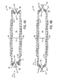
- FIGS. 4A and 4B are schematic cross-sectional side views of synthetic jet actuators according to embodiments of the invention.
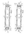
- FIG. 5 is a schematic cross-sectional side view of a synthetic jet actuator according to an embodiment of the invention.
- FIG. 6 is a schematic cross-sectional side view of a synthetic jet actuator according to an embodiment of the invention.
- FIG. 7 is a schematic cross-sectional side view of a synthetic jet actuator according to an embodiment of the invention.
- FIG. 8 is a schematic cross-sectional side view of a synthetic jet actuator according to an embodiment of the invention.
- FIG. 9 is a schematic cross-sectional side view of a synthetic jet actuator according to an embodiment of the invention.
- Embodiments of the invention provide a synthetic jet actuator and method of manufacturing thereof.
- a spacer element is provided between deflecting plates of the synthetic jet actuator that deforms in a bending motion when the first and second plates are caused to deflect, thereby lowering a structural natural frequency of the synthetic jet actuator.
- the synthetic jet actuator 50 includes a pair of synthetic jet plates 52, 54, shown in FIGS. 4A and 4B as a first plate 52 and an opposing second plate 54 arranged parallel thereto. Attached to at least one of the first and second plates 52, 54, or to both of the first and second plates as shown in FIGS. 4A and 4B , are actuator elements 56, 58 configured to cause displacement of the plates.
- actuator elements 56, 58 comprise piezoelectric elements (e.g., piezoelectric disks) that are configured to periodically receive an electric charge from a controller/power source (not shown), and undergo mechanical stress and/or strain responsive to the charge.
- the stress/strain of piezoelectric elements 56, 58 causes deflection of first and second plates 52, 54 such that, for example, a time-harmonic motion or vibration of the plates is achieved.
- the piezoelectric elements 56, 58 coupled to the first and second plates 52, 54, respectively can be selectively controlled to cause vibration of one or both of the plates so as to control the volume and velocity of a synthetic jet stream 60 expelled from the synthetic jet actuator 50.
- the first and second plates 52, 54 are maintained in a spaced apart relationship by a spacer element 62 positioned therebetween.
- the combination of first and second plates 52, 54 and spacer element 62 define a chamber or volume 64 within the synthetic jet actuator 50.
- the spacer element 62 includes therein one or more orifices 66 to place the chamber 64 in fluid communication with a surrounding, external environment 68. As shown in FIGS.
- a pair of orifices 66 is formed in spacer element 62 to allow for the drawing in and exhaustion of an ambient fluid into and out of the synthetic jet actuator 50, although it is recognized that a greater or lesser number of orifices could be formed in spacer element 62 (e.g., 1, 3, or 4 orifices, for example).
- the piezoelectric elements 56, 58 coupled to the first and second plates 52, 54 are selectively controlled to cause vibration of one or both of the plates so as to control the volume and velocity of synthetic jet stream 60 expelled from one or both of the orifices 66.
- spacer element 62 of synthetic jet actuator 50 is formed as a flexible wall member (i.e., flexible ring) having a concave shape when at rest. That is, spacer element 62 is formed to have a concave shape absent from any deflection of the plates 52, 54 induced by actuator elements 56, 58.
- the flexible wall member 62 is constructed such that, upon deflection of the plates 52, 54 induced by actuator elements 56, 58, the flexible wall member 62 is caused to deform in an inward and outward bending motion.
- the inward and outward bending motion of flexible wall member 62 is in a direction perpendicular to a direction of the deflection of the first and second plates 52, 54, as indicated by arrow 70 (indicating the inward and outward bending direction) and arrow 72 (indicating the direction of deflection of the plates), respectively.
- the concave structure of flexible wall member 62, and the inward and outward bending motion thereof upon deflection of the plates induced by actuator elements 56, 58, provides a spacer element having a low spring constant.
- the low spring constant of flexible wall member 62 acts to reduce a natural frequency of synthetic jet actuator 50 at a maximum deflection of the first and second plates 52, 54, thereby allowing the synthetic jet actuator 50 to operate at a low frequency and reduce associated noise output and power consumption.
- spacer element 62 of synthetic jet actuator 50 is formed as a flexible wall member (i.e., flexible ring) having a convex shape when at rest. That is, spacer element 62 is formed to have a convex shape absent from any deflection of the plates 52, 54 induced by actuator elements 56, 58.
- the flexible wall member 62 is constructed such that, upon deflection of the plates 52, 54 induced by actuator elements 56, 58, the flexible wall member 62 is caused to deform in an inward and outward bending motion, as indicated by arrow 70.
- the convex structure of flexible wall member 62, and the inward and outward bending motion thereof upon deflection of the plates induced by actuator elements 56, 58, provides a spacer element having a low spring constant, thereby reducing a natural frequency of synthetic jet actuator 50.
- flexible wall member 62 is formed from an array compliant elastomer layers 74 arranged in either a concave ( FIG. 4A ) or convex ( FIG. 4B ) arrangement.
- an array of silicone layers may be provided that are layered on one another to provide a concave or convex shaped flexible wall member/ring, with at least some of the layers 74 having a gap formed therein that collectively form orifice 66.
- other flexible materials such as polycarbonate and Kapton, for example, could also be used to form the layers 74 of flexible wall member 62.
- flexible wall member 62 deforms in a bending motion in response to deflection of the plates 52, 54 induced by actuator elements 56, 58 rather than a compression and expansion type of deformation. That is, a spacing element formed as a solid ring of beaded material, for example, would undergo compression and expansion deformation in response to deflection of the plates 52, 54 induced by actuator elements 56, 58 rather than the bending deformation undergone by flexible wall member 62.
- the bending deformation/translation of flexible wall member 62 provides a spacing element having a lower spring constant than a spacer member that undergoes compression/expansion deformation, thereby reducing a natural frequency of synthetic jet actuator 50.
- the synthetic jet actuator 76 includes a first synthetic jet plate 52 and an opposing second synthetic jet plate 54 arranged parallel thereto. Attached to at least one of the first and second plates 52, 54, or to both of the first and second plates as shown in FIG. 5 , are actuator elements 56, 58 configured to cause displacement of the plates.
- actuator elements 56, 58 comprise piezoelectric elements (e.g., piezoelectric disks) that are configured to periodically receive an electric charge from a controller/power source (not shown), and undergo mechanical stress and/or strain responsive to the charge.
- the stress/strain of piezoelectric elements 56, 58 causes deflection of first and second plates 52, 54 such that, for example, a time-harmonic motion or vibration of the plates is achieved. It is recognized that the piezoelectric elements 56, 58 coupled to the first and second plates 52, 54, respectively, can be selectively controlled to cause vibration of one or both of the plates so as to control the volume and velocity of a synthetic jet stream 60 expelled from the synthetic jet actuator 76.
- the first and second plates 52, 54 and maintained in a spaced apart relationship by a spacer element 78 positioned therebetween.
- the combination of first and second plates 52, 54 and spacer element 78 define a chamber or volume 64 within the synthetic jet actuator 76.
- the spacer element 78 includes therein one or more orifices 66 to place the chamber 64 in fluid communication with a surrounding, external environment 68. As shown in FIG. 5 , a pair of orifices 66 is formed in spacer element 78 to allow for the drawing in and exhaustion of an ambient fluid into and out of the synthetic jet actuator 76.
- the piezoelectric elements 56, 58 coupled to the first and second plates 52, 54 are selectively controlled to cause vibration of one or both of the plates so as to control the volume and velocity of synthetic jet stream 60 expelled from one or both of the orifices 66.
- spacer element 78 of synthetic jet actuator 76 is formed as a half-section tube or a tube having a slit formed therein.
- the spacer element 78 may be formed from vascular tubing (made with silicone or other compliant materials) or an o-ring, for example, that is cut in half or has a slit 80 cut therein.
- the half-section tube 78 is thus constructed such that, upon deflection of the plates 52, 54 induced by actuator elements 56, 58, the half-section tube 78 is caused to deform in an inward and outward bending motion.
- half-section tube 78 The inward and outward bending motion of half-section tube 78 is in a direction perpendicular to a direction of the deflection of the first and second plates 52, 54, as indicated by arrow 70 (indicating the inward and outward bending direction) and arrow 72 (indicating the direction of deflection of the plates), respectively.
- the structure of half-section tube 78, and the inward and outward bending motion thereof upon deflection of the plates induced by actuator elements 56, 58, provides a spacer element having a low spring constant.
- the low spring constant of half-section tube 78 acts to reduce a natural frequency of synthetic jet actuator 76 at a maximum deflection of the first and second plates 52, 54, thereby allowing the synthetic jet actuator 76 to operate at a low frequency and reduce associated noise output and power consumption.
- a synthetic jet actuator 82 having a spacer element 84 formed as a bellows-shaped flexible wall.
- the bellows-shaped flexible wall 84 is positioned between the first and second plates 52, 54 inside an outer edge 86 thereof (i.e., an "inner bellows").
- the bellows-shaped flexible wall 84 is constructed to have a plurality of pliable folds therein such that, upon deflection of the plates 52, 54 induced by actuator elements 56, 58, the bellows-shaped flexible wall 84 is caused to deform in an inward and outward bending motion.
- bellows-shaped flexible wall 84 The inward and outward bending motion of bellows-shaped flexible wall 84 is in a direction perpendicular to a direction of the deflection of the first and second plates 52, 54, as indicated by arrow 70 (indicating the inward and outward bending direction) and arrow 72 (indicating the direction of deflection of the plates), respectively.
- the structure of bellows-shaped flexible wall 84, and the inward and outward bending motion thereof upon deflection of the plates induced by actuator elements 56, 58, provides a spacer element having a low spring constant.
- the low spring constant of bellows-shaped flexible wall 84 acts to reduce a natural frequency of synthetic jet actuator 82 at a maximum deflection of the first and second plates 52, 54, thereby allowing the synthetic jet actuator 82 to operate at a low frequency and reduce associated noise output and power consumption.
- the synthetic jet actuator 88 includes therein a spacer element 90 formed as a bellows-shaped flexible wall that is configured to maintain plate 52 and plate 54 in a spaced apart relationship.
- bellows-shaped flexible wall 90 is attached to an outer surface 92 of each of the first and second plates 52, 54 adjacent an outer perimeter 94 thereof (i.e., an "outer bellows").
- the bellows-shaped flexible wall 90 extends out from first and second plates 52, 54 such that a height thereof is greater than a separation distance between the first and second plates.
- the bellows-shaped flexible wall 90 also extends out from first and second plates 52, 54 past the outer perimeter 94 thereof, such that a horizontal dimension (in direction 70) of the overall synthetic jet actuator 88 is increased.
- the bellows-shaped flexible wall 90 is constructed to have a plurality of pliable folds therein such that, upon deflection of the plates 52, 54 induced by actuator elements 56, 58, the bellows-shaped flexible wall 84 is caused to deform in an inward and outward bending motion.
- bellows-shaped flexible wall 90 is in a direction 70 perpendicular to a direction 72 of the deflection of the first and second plates 52, 54 and acts to reduce a natural frequency of synthetic jet actuator 88 at a maximum deflection of the first and second plates 52, 54, thereby allowing the synthetic jet actuator 88 to operate at a low frequency and reduce associated noise output and power consumption.
- a synthetic jet actuator 96 having a spacer element 98 formed as a box-shaped flexible wall structure that is configured to maintain plate 52 and plate 54 in a spaced apart relationship.
- flexible wall structure 98 is attached to the outer surface 92 of each of the first and second plates 52, 54 adjacent the outer perimeter 94 thereof.
- the flexible wall structure 98 extends out from first and second plates 52, 54 such that a height thereof is greater than a separation distance between the first and second plates.
- the flexible wall structure 98 also extends out from first and second plates 52, 54 past the outer perimeter 94 thereof, such that a horizontal dimension (in direction 70) of the overall synthetic jet actuator 96 is increased.
- the flexible wall structure 98 is constructed such that, upon deflection of the plates 52, 54 induced by actuator elements 56, 58, the flexible wall structure 98 is caused to deform in an inward and outward bending motion.
- the inward and outward bending motion of flexible wall structure 98 is in a direction 70 perpendicular to a direction 72 of the deflection of the first and second plates 52, 54 and acts to reduce a natural frequency of synthetic jet actuator 96 at a maximum deflection of the first and second plates 52, 54, thereby allowing the synthetic jet actuator 96 to operate at a low frequency and reduce associated noise output and power consumption.
- the synthetic jet actuator 100 includes therein a spacer element 102 formed as a composite spacer element that is configured to maintain plate 52 and plate 54 in a spaced apart relationship.
- the composite spacer element 102 includes a first flexible extension member 104 attached to an inner surface 106 of the first plate 52 that extends outward past an outer perimeter 94 thereof and a second flexible extension member 108 attached to an inner surface 110 of the second plate 54 and extending outward past an outer perimeter 94 thereof.
- a rigid wall member 112 having orifices 66 formed therein is positioned between first flexible extension member 104 and second flexible extension member 108 to maintain the first and second flexible extension members in a spaced apart relationship.
- the composite spacer element 102 is constructed such that, upon deflection of the plates 52, 54 induced by actuator elements 56, 58, first flexible extension member 104 and second flexible extension member 108 are caused to deform in an upward and downward bending motion.
- the upward and downward bending motion of first flexible extension member 104 and second flexible extension member 108 is in a direction 72 parallel to a direction 72 of the deflection of the first and second plates 52, 54, and acts to reduce a natural frequency of synthetic jet actuator 100 at a maximum deflection of the first and second plates 52, 54, thereby allowing the synthetic jet actuator 100 to operate at a low frequency and reduce associated noise output and power consumption.
- FIGS. 4-9 are shown and described as having multiple orifices therein, it is also envisioned that embodiments of the invention could be used with single orifice synthetic jet actuators. Additionally, while the synthetic jet actuators of FIGS. 4-9 are shown and described as having an actuator element included on each of first and second plates, it is also envisioned that embodiments of the invention could include only a single actuator element positioned on one of the plates.
- embodiments of the synthetic jet actuators shown in FIGS. 4-9 incorporate a spacer element/member therein that functions to lower a structural natural operating frequency of the synthetic jet actuator.
- the structural natural operating frequency of the synthetic jet actuator is at or below 400 Hz, as compared to prior art synthetic jet actuators that can typically operate at a structural natural operating frequency of 600 Hz or more.
- the level of acoustic noise generated during operation of the synthetic jet actuators set forth above is also lowered based on the structure/design of the spacer elements incorporated therein.
- the acoustic noise levels associated with operation of the synthetic jet actuators is at or below a level of 27 dBA, as compared to prior art synthetic jet actuators that can typically operate at a noise level of 32 dBA or more.
- a synthetic jet actuator includes a first plate, a second plate spaced apart from the first plate and arranged parallelly thereto, and a spacer element configured to space the first plate apart from the second plate and define a chamber along with the first and second plates.
- the spacer element includes at least one orifice formed therein such that the chamber is in fluid communication with an environment external to the chamber and the spacer element is constructed to deform in a bending motion in response to a deflection of at least one of the first and second plates.
- a method of manufacturing a synthetic jet actuator includes providing a pair of synthetic jet plates comprising a first plate and a second plate and attaching a spacing member to the pair of synthetic jet plates to maintain the first plate and the second plate in a spaced apart relationship and so as to define a chamber.
- the spacing member is configured to bendingly deform in response to the deflection of the first and second plates and includes at least one orifice formed therein such that the chamber is in fluid communication with an external environment.
- the method also includes coupling an actuator element to at least one of the first and second plates to selectively cause deflection thereof, thereby changing a volume within the chamber so that a series of fluid vortices are generated and projected to the external environment from the at least one orifice of the spacer element.
- a synthetic jet actuator includes a first plate and a second plate spaced apart from the first plate and arranged parallelly thereto.
- the synthetic jet actuator also includes a spacer element configured to maintain the first plate and the second plate in a spaced apart relationship so as to define a chamber, the spacer element having at least one orifice therein such that the chamber is in fluid communication with an external environment.
- the synthetic jet actuator further includes an actuator element coupled to at least one of the first and second plates to selectively cause deflection thereof, thereby changing a volume within the chamber so that a series of fluid vortices are generated and projected to the external environment from the at least one orifice of the spacer element.
- the spacer element of the synthetic jet actuator comprises a pliant member configured to deflect in a bending motion in response to the deflection of the first and second plates.
Landscapes
- Engineering & Computer Science (AREA)
- Physics & Mathematics (AREA)
- Fluid Mechanics (AREA)
- Mechanical Engineering (AREA)
- General Engineering & Computer Science (AREA)
- Reciprocating Pumps (AREA)
- Actuator (AREA)
Abstract
Description
- Embodiments of the invention relate generally to synthetic jet actuators and, more particularly, to synthetic jet actuators having an element therein for lowering the structural natural frequency thereof.
- Synthetic jet actuators are a widely-used technology that generates a synthetic jet of fluid to influence the flow of that fluid over a surface. A typical synthetic jet actuator comprises a housing defining an internal chamber. An orifice is present in a wall of the housing. The actuator further includes a mechanism in or about the housing for periodically changing the volume within the internal chamber so that a series of fluid vortices are generated and projected in an external environment out from the orifice of the housing. Examples of volume changing mechanisms may include, for example, a piston positioned in the jet housing to move fluid in and out of the orifice during reciprocation of the piston or a flexible diaphragm as a wall of the housing. The flexible diaphragm is typically actuated by a piezoelectric actuator or other appropriate means.
- Typically, a control system is used to create time-harmonic motion of the volume changing mechanism. As the mechanism decreases the chamber volume, fluid is ejected from the chamber through the orifice. As the fluid passes through the orifice, sharp edges of the orifice separate the flow to create vortex sheets that roll up into vortices. These vortices move away from the edges of the orifice under their own self-induced velocity. As the mechanism increases the chamber volume, ambient fluid is drawn into the chamber from large distances from the orifice. Since the vortices have already moved away from the edges of the orifice, they are not affected by the ambient fluid entering into the chamber. As the vortices travel away from the orifice, they synthesize a jet of fluid, i.e., a "synthetic jet."
- Referring to
FIGS. 1-3 , asynthetic jet actuator 10 as known in the art, and the operation thereof, is shown for purposes of describing the general operation of a synthetic jet actuator. Thesynthetic jet actuator 10 includes ahousing 11 defining and enclosing aninternal chamber 14. Thehousing 11 andchamber 14 can take virtually any geometric configuration, but for purposes of discussion and understanding, thehousing 11 is shown in cross-section inFIG. 1 to have arigid side wall 12, a rigidfront wall 13, and arear diaphragm 18 that is flexible to an extent to permit movement of thediaphragm 18 inwardly and outwardly relative to thechamber 14. Thefront wall 13 has anorifice 16 of any geometric shape. The orifice diametrically opposes therear diaphragm 18 and connects theinternal chamber 14 to an external environment havingambient fluid 39. - The
flexible diaphragm 18 may be controlled to move by anysuitable control system 24. For example, thediaphragm 18 may be equipped with a metal layer, and a metal electrode may be disposed adjacent to but spaced from the metal layer so that thediaphragm 18 can be moved via an electrical bias imposed between the electrode and the metal layer. Moreover, the generation of the electrical bias can be controlled by any suitable device, for example but not limited to, a computer, logic processor, or signal generator. Thecontrol system 24 can cause thediaphragm 18 to move periodically, or modulate in time-harmonic motion, and force fluid in and out of theorifice 16. Alternatively, a piezoelectric actuator could be attached to thediaphragm 18. The control system would, in that case, cause the piezoelectric actuator to vibrate and thereby move thediaphragm 18 in time-harmonic motion. - The operation of the
synthetic jet actuator 10 is described with reference toFIGS. 2 and 3. FIG. 2 depicts thesynthetic jet actuator 10 as thediaphragm 18 is controlled to move inward into thechamber 14, as depicted byarrow 26. Thechamber 14 has its volume decreased and fluid is ejected through theorifice 16. As the fluid exits thechamber 14 through theorifice 16, the flow separates atsharp orifice edges 30 and createsvortex sheets 32 which roll intovortices 34 and begin to move away from theorifice edges 30 in the direction indicated byarrow 36. -
FIG. 3 depicts thesynthetic jet actuator 10 as thediaphragm 18 is controlled to move outward with respect to thechamber 14, as depicted byarrow 38. Thechamber 14 has its volume increased andambient fluid 39 rushes into thechamber 14 as depicted by the set ofarrows 40. Thediaphragm 18 is controlled by thecontrol system 24 so that when thediaphragm 18 moves away from thechamber 14, thevortices 34 are already removed from theorifice edges 30 and thus are not affected by theambient fluid 39 being drawn into thechamber 14. Meanwhile, a jet ofambient fluid 39 is synthesized by thevortices 34 creating strong entrainment of ambient fluid drawn from large distances away from theorifice 16. - A drawback of existing synthetic jet designs, such as that shown and described in
FIGS. 1-3 , is the noise generated from operation of the synthetic jet. Audible noise is inherent in the operation of synthetic jets as a result of the flexible diaphragm being caused to deflect in an alternating motion, and the natural frequencies of the synthetic jet's various operational modes (structural, disk-bending, and acoustic) impact the amount of noise generated during operation. According to existing designs, a structural natural frequency of a synthetic jet may reach levels of 600 Hz, resulting in a high level of audible noise being generated, which is highly undesirable. - Another drawback of existing synthetic jet designs is the amount of power consumed during operation of the synthetic jet. A high structural natural frequency of the synthetic jet corresponds to a higher amount of power that is needed to be provided to the synthetic jet to deflect the diaphragm. High rates of power consumption not only increase the cost of operating the synthetic jet, but also decrease the efficiency of the synthetic jet. For example, when the synthetic jet is used as a cooling device, convection cooling is negatively affected by high rates of power consumption, as such increased power consumption generates unwanted heat.
- The noise level and rates of power consumption are both a result of the natural frequency of the synthetic jet's maximum deflection, which in turn is a result of the material properties and shape of components in the synthetic jet actuator. Specifically, the shape of components in existing synthetic jet actuators results is an increased spring constant associated therewith, thereby leading to an increased structural natural frequency of the synthetic jet actuator.
- Accordingly, it is desirable to provide a synthetic jet having a low structural natural frequency in order to reduce the amount of noise generated from operation of the synthetic jet and to lower the amount of power consumed during operation of the synthetic jet.
- Embodiments of the invention overcome the aforementioned drawbacks by providing a synthetic jet actuator and method of manufacturing thereof. A spacer element is provided between deflecting plates of the synthetic jet actuator that deforms in a bending motion when the first and second plates are caused to deflect, thereby lowering a structural natural frequency of the synthetic jet actuator.
- In accordance with one aspect of the invention, a synthetic jet actuator includes a first plate, a second plate spaced apart from the first plate and arranged parallelly thereto, and a spacer element configured to space the first plate apart from the second plate and define a chamber along with the first and second plates. The spacer element includes at least one orifice formed therein such that the chamber is in fluid communication with an environment external to the chamber and the spacer element is constructed to deform in a bending motion in response to a deflection of at least one of the first and second plates.
- In accordance with another aspect of the invention, a method of manufacturing a synthetic jet actuator includes providing a pair of synthetic jet plates comprising a first plate and a second plate and attaching a spacing member to the pair of synthetic jet plates to maintain the first plate and the second plate in a spaced apart relationship and so as to define a chamber. The spacing member is configured to bendingly deform in response to the deflection of the first and second plates and includes at least one orifice formed therein such that the chamber is in fluid communication with an external environment. The method also includes coupling an actuator element to at least one of the first and second plates to selectively cause deflection thereof, thereby changing a volume within the chamber so that a series of fluid vortices are generated and projected to the external environment from the at least one orifice of the spacer element.
- In accordance with yet another aspect of the invention, a synthetic jet actuator includes a first plate and a second plate spaced apart from the first plate and arranged parallelly thereto. The synthetic jet actuator also includes a spacer element configured to maintain the first plate and the second plate in a spaced apart relationship so as to define a chamber, the spacer element having at least one orifice therein such that the chamber is in fluid communication with an external environment. The synthetic jet actuator further includes an actuator element coupled to at least one of the first and second plates to selectively cause deflection thereof, thereby changing a volume within the chamber so that a series of fluid vortices are generated and projected to the external environment from the at least one orifice of the spacer element. The spacer element of the synthetic jet actuator comprises a pliant member configured to deflect in a bending motion in response to the deflection of the first and second plates.
- These and other advantages and features will be more readily understood from the following detailed description of preferred embodiments of the invention that is provided in connection with the accompanying drawings.
- The drawings illustrate embodiments presently contemplated for carrying out the invention.
- In the drawings:
-
FIG. 1 is a cross-section of a prior art zero net mass flux synthetic jet actuator with a control system. -
FIG. 2 is a cross-section of the synthetic jet actuator ofFIG. 1 depicting the jet as the control system causes the diaphragm to travel inward, toward the orifice. -
FIG. 3 is a cross-section of the synthetic jet actuator ofFIG. 1 depicting the jet as the control system causes the diaphragm to travel outward, away from the orifice. -
FIGS. 4A and 4B are schematic cross-sectional side views of synthetic jet actuators according to embodiments of the invention. -
FIG. 5 is a schematic cross-sectional side view of a synthetic jet actuator according to an embodiment of the invention. -
FIG. 6 is a schematic cross-sectional side view of a synthetic jet actuator according to an embodiment of the invention. -
FIG. 7 is a schematic cross-sectional side view of a synthetic jet actuator according to an embodiment of the invention. -
FIG. 8 is a schematic cross-sectional side view of a synthetic jet actuator according to an embodiment of the invention. -
FIG. 9 is a schematic cross-sectional side view of a synthetic jet actuator according to an embodiment of the invention. - Embodiments of the invention provide a synthetic jet actuator and method of manufacturing thereof. A spacer element is provided between deflecting plates of the synthetic jet actuator that deforms in a bending motion when the first and second plates are caused to deflect, thereby lowering a structural natural frequency of the synthetic jet actuator.
- Referring now to
FIGS. 4A and 4B , asynthetic jet actuator 50 is shown according to embodiments of the invention. Thesynthetic jet actuator 50 includes a pair ofsynthetic jet plates FIGS. 4A and 4B as afirst plate 52 and an opposingsecond plate 54 arranged parallel thereto. Attached to at least one of the first andsecond plates FIGS. 4A and 4B , areactuator elements actuator elements piezoelectric elements second plates piezoelectric elements second plates synthetic jet stream 60 expelled from thesynthetic jet actuator 50. - The first and
second plates spacer element 62 positioned therebetween. The combination of first andsecond plates spacer element 62 define a chamber orvolume 64 within thesynthetic jet actuator 50. Thespacer element 62 includes therein one ormore orifices 66 to place thechamber 64 in fluid communication with a surrounding,external environment 68. As shown inFIGS. 4A and 4B , a pair oforifices 66 is formed inspacer element 62 to allow for the drawing in and exhaustion of an ambient fluid into and out of thesynthetic jet actuator 50, although it is recognized that a greater or lesser number of orifices could be formed in spacer element 62 (e.g., 1, 3, or 4 orifices, for example). As set forth above, thepiezoelectric elements second plates synthetic jet stream 60 expelled from one or both of theorifices 66. - As shown in
FIG. 4A , according to one embodiment,spacer element 62 ofsynthetic jet actuator 50 is formed as a flexible wall member (i.e., flexible ring) having a concave shape when at rest. That is,spacer element 62 is formed to have a concave shape absent from any deflection of theplates actuator elements flexible wall member 62 is constructed such that, upon deflection of theplates actuator elements flexible wall member 62 is caused to deform in an inward and outward bending motion. The inward and outward bending motion offlexible wall member 62 is in a direction perpendicular to a direction of the deflection of the first andsecond plates flexible wall member 62, and the inward and outward bending motion thereof upon deflection of the plates induced byactuator elements flexible wall member 62 acts to reduce a natural frequency ofsynthetic jet actuator 50 at a maximum deflection of the first andsecond plates synthetic jet actuator 50 to operate at a low frequency and reduce associated noise output and power consumption. - As shown in
FIG. 4B , according to one embodiment,spacer element 62 ofsynthetic jet actuator 50 is formed as a flexible wall member (i.e., flexible ring) having a convex shape when at rest. That is,spacer element 62 is formed to have a convex shape absent from any deflection of theplates actuator elements flexible wall member 62 is constructed such that, upon deflection of theplates actuator elements flexible wall member 62 is caused to deform in an inward and outward bending motion, as indicated byarrow 70. The convex structure offlexible wall member 62, and the inward and outward bending motion thereof upon deflection of the plates induced byactuator elements synthetic jet actuator 50. - According to an exemplary embodiment of the invention,
flexible wall member 62 is formed from an array compliant elastomer layers 74 arranged in either a concave (FIG. 4A ) or convex (FIG. 4B ) arrangement. For example, an array of silicone layers may be provided that are layered on one another to provide a concave or convex shaped flexible wall member/ring, with at least some of thelayers 74 having a gap formed therein that collectively formorifice 66. It is also recognized that other flexible materials such as polycarbonate and Kapton, for example, could also be used to form thelayers 74 offlexible wall member 62. - In each of the embodiments of the
synthetic jet actuator 50 ofFIGS. 4A and 4B , it is recognized thatflexible wall member 62 deforms in a bending motion in response to deflection of theplates actuator elements plates actuator elements flexible wall member 62. The bending deformation/translation offlexible wall member 62 provides a spacing element having a lower spring constant than a spacer member that undergoes compression/expansion deformation, thereby reducing a natural frequency ofsynthetic jet actuator 50. - Referring now to
FIG. 5 , asynthetic jet actuator 76 is shown according to another embodiment of the invention. Thesynthetic jet actuator 76 includes a firstsynthetic jet plate 52 and an opposing secondsynthetic jet plate 54 arranged parallel thereto. Attached to at least one of the first andsecond plates FIG. 5 , areactuator elements actuator elements piezoelectric elements second plates piezoelectric elements second plates synthetic jet stream 60 expelled from thesynthetic jet actuator 76. - The first and
second plates spacer element 78 positioned therebetween. The combination of first andsecond plates spacer element 78 define a chamber orvolume 64 within thesynthetic jet actuator 76. Thespacer element 78 includes therein one ormore orifices 66 to place thechamber 64 in fluid communication with a surrounding,external environment 68. As shown inFIG. 5 , a pair oforifices 66 is formed inspacer element 78 to allow for the drawing in and exhaustion of an ambient fluid into and out of thesynthetic jet actuator 76. That is, as set forth above, thepiezoelectric elements second plates synthetic jet stream 60 expelled from one or both of theorifices 66. - As shown in
FIG. 5 , according to an embodiment of the invention,spacer element 78 ofsynthetic jet actuator 76 is formed as a half-section tube or a tube having a slit formed therein. Thespacer element 78 may be formed from vascular tubing (made with silicone or other compliant materials) or an o-ring, for example, that is cut in half or has aslit 80 cut therein. The half-section tube 78 is thus constructed such that, upon deflection of theplates actuator elements section tube 78 is caused to deform in an inward and outward bending motion. The inward and outward bending motion of half-section tube 78 is in a direction perpendicular to a direction of the deflection of the first andsecond plates section tube 78, and the inward and outward bending motion thereof upon deflection of the plates induced byactuator elements section tube 78 acts to reduce a natural frequency ofsynthetic jet actuator 76 at a maximum deflection of the first andsecond plates synthetic jet actuator 76 to operate at a low frequency and reduce associated noise output and power consumption. - Referring now to
FIG. 6 , according to another embodiment of the invention, asynthetic jet actuator 82 is provided having aspacer element 84 formed as a bellows-shaped flexible wall. The bellows-shapedflexible wall 84 is positioned between the first andsecond plates outer edge 86 thereof (i.e., an "inner bellows"). The bellows-shapedflexible wall 84 is constructed to have a plurality of pliable folds therein such that, upon deflection of theplates actuator elements flexible wall 84 is caused to deform in an inward and outward bending motion. The inward and outward bending motion of bellows-shapedflexible wall 84 is in a direction perpendicular to a direction of the deflection of the first andsecond plates flexible wall 84, and the inward and outward bending motion thereof upon deflection of the plates induced byactuator elements flexible wall 84 acts to reduce a natural frequency ofsynthetic jet actuator 82 at a maximum deflection of the first andsecond plates synthetic jet actuator 82 to operate at a low frequency and reduce associated noise output and power consumption. - Referring now to
FIG. 7 , asynthetic jet actuator 88 is shown according to another embodiment of the invention. Thesynthetic jet actuator 88 includes therein aspacer element 90 formed as a bellows-shaped flexible wall that is configured to maintainplate 52 andplate 54 in a spaced apart relationship. As shown inFIG. 7 , bellows-shapedflexible wall 90 is attached to anouter surface 92 of each of the first andsecond plates outer perimeter 94 thereof (i.e., an "outer bellows"). The bellows-shapedflexible wall 90 extends out from first andsecond plates flexible wall 90 also extends out from first andsecond plates outer perimeter 94 thereof, such that a horizontal dimension (in direction 70) of the overallsynthetic jet actuator 88 is increased. The bellows-shapedflexible wall 90 is constructed to have a plurality of pliable folds therein such that, upon deflection of theplates actuator elements flexible wall 84 is caused to deform in an inward and outward bending motion. The inward and outward bending motion of bellows-shapedflexible wall 90 is in adirection 70 perpendicular to adirection 72 of the deflection of the first andsecond plates synthetic jet actuator 88 at a maximum deflection of the first andsecond plates synthetic jet actuator 88 to operate at a low frequency and reduce associated noise output and power consumption. - Referring now to
FIG. 8 , according to another embodiment of the invention, asynthetic jet actuator 96 is provided having aspacer element 98 formed as a box-shaped flexible wall structure that is configured to maintainplate 52 andplate 54 in a spaced apart relationship. As shown inFIG. 8 ,flexible wall structure 98 is attached to theouter surface 92 of each of the first andsecond plates outer perimeter 94 thereof. Theflexible wall structure 98 extends out from first andsecond plates flexible wall structure 98 also extends out from first andsecond plates outer perimeter 94 thereof, such that a horizontal dimension (in direction 70) of the overallsynthetic jet actuator 96 is increased. Theflexible wall structure 98 is constructed such that, upon deflection of theplates actuator elements flexible wall structure 98 is caused to deform in an inward and outward bending motion. The inward and outward bending motion offlexible wall structure 98 is in adirection 70 perpendicular to adirection 72 of the deflection of the first andsecond plates synthetic jet actuator 96 at a maximum deflection of the first andsecond plates synthetic jet actuator 96 to operate at a low frequency and reduce associated noise output and power consumption. - Referring now to
FIG. 9 , asynthetic jet actuator 100 is shown according to another embodiment of the invention. Thesynthetic jet actuator 100 includes therein aspacer element 102 formed as a composite spacer element that is configured to maintainplate 52 andplate 54 in a spaced apart relationship. Thecomposite spacer element 102 includes a firstflexible extension member 104 attached to aninner surface 106 of thefirst plate 52 that extends outward past anouter perimeter 94 thereof and a secondflexible extension member 108 attached to aninner surface 110 of thesecond plate 54 and extending outward past anouter perimeter 94 thereof. Arigid wall member 112 havingorifices 66 formed therein is positioned between firstflexible extension member 104 and secondflexible extension member 108 to maintain the first and second flexible extension members in a spaced apart relationship. Thecomposite spacer element 102 is constructed such that, upon deflection of theplates actuator elements flexible extension member 104 and secondflexible extension member 108 are caused to deform in an upward and downward bending motion. The upward and downward bending motion of firstflexible extension member 104 and secondflexible extension member 108 is in adirection 72 parallel to adirection 72 of the deflection of the first andsecond plates synthetic jet actuator 100 at a maximum deflection of the first andsecond plates synthetic jet actuator 100 to operate at a low frequency and reduce associated noise output and power consumption. - While the synthetic jet actuators of
FIGS. 4-9 are shown and described as having multiple orifices therein, it is also envisioned that embodiments of the invention could be used with single orifice synthetic jet actuators. Additionally, while the synthetic jet actuators ofFIGS. 4-9 are shown and described as having an actuator element included on each of first and second plates, it is also envisioned that embodiments of the invention could include only a single actuator element positioned on one of the plates. - Beneficially, embodiments of the synthetic jet actuators shown in
FIGS. 4-9 incorporate a spacer element/member therein that functions to lower a structural natural operating frequency of the synthetic jet actuator. According to the embodiments set forth above, the structural natural operating frequency of the synthetic jet actuator is at or below 400 Hz, as compared to prior art synthetic jet actuators that can typically operate at a structural natural operating frequency of 600 Hz or more. Additionally, the level of acoustic noise generated during operation of the synthetic jet actuators set forth above is also lowered based on the structure/design of the spacer elements incorporated therein. The acoustic noise levels associated with operation of the synthetic jet actuators is at or below a level of 27 dBA, as compared to prior art synthetic jet actuators that can typically operate at a noise level of 32 dBA or more. - While the invention has been described in detail in connection with only a limited number of embodiments, it should be readily understood that the invention is not limited to such disclosed embodiments. Rather, the invention can be modified to incorporate any number of variations, alterations, substitutions or equivalent arrangements not heretofore described, but which are commensurate with the spirit and scope of the invention. Additionally, while various embodiments of the invention have been described, it is to be understood that aspects of the invention may include only some of the described embodiments. Accordingly, the invention is not to be seen as limited by the foregoing description, but is only limited by the scope of the appended claims.
- Therefore, according to one embodiment of the invention, a synthetic jet actuator includes a first plate, a second plate spaced apart from the first plate and arranged parallelly thereto, and a spacer element configured to space the first plate apart from the second plate and define a chamber along with the first and second plates. The spacer element includes at least one orifice formed therein such that the chamber is in fluid communication with an environment external to the chamber and the spacer element is constructed to deform in a bending motion in response to a deflection of at least one of the first and second plates.
- According to another embodiment of the invention, a method of manufacturing a synthetic jet actuator includes providing a pair of synthetic jet plates comprising a first plate and a second plate and attaching a spacing member to the pair of synthetic jet plates to maintain the first plate and the second plate in a spaced apart relationship and so as to define a chamber. The spacing member is configured to bendingly deform in response to the deflection of the first and second plates and includes at least one orifice formed therein such that the chamber is in fluid communication with an external environment. The method also includes coupling an actuator element to at least one of the first and second plates to selectively cause deflection thereof, thereby changing a volume within the chamber so that a series of fluid vortices are generated and projected to the external environment from the at least one orifice of the spacer element.
- According to yet another embodiment of the invention, a synthetic jet actuator includes a first plate and a second plate spaced apart from the first plate and arranged parallelly thereto. The synthetic jet actuator also includes a spacer element configured to maintain the first plate and the second plate in a spaced apart relationship so as to define a chamber, the spacer element having at least one orifice therein such that the chamber is in fluid communication with an external environment. The synthetic jet actuator further includes an actuator element coupled to at least one of the first and second plates to selectively cause deflection thereof, thereby changing a volume within the chamber so that a series of fluid vortices are generated and projected to the external environment from the at least one orifice of the spacer element. The spacer element of the synthetic jet actuator comprises a pliant member configured to deflect in a bending motion in response to the deflection of the first and second plates.
- Various aspects of the present invention are defined in the following numbered clauses:
- 1. A synthetic jet actuator comprising:
- a first plate;
- a second plate spaced apart from the first plate and arranged parallelly thereto; and
- a spacer element configured to space the first plate apart from the second plate and defining a chamber along with the first and second plates, the spacer element having at least one orifice formed therein such that the chamber is in fluid communication with an environment external to the chamber; and
- wherein the spacer element is constructed to deform in a bending motion in response to a deflection of at least one of the first and second plates.
- 2. The synthetic jet actuator of clause 1, wherein the spacer element is constructed to deform in an inward and outward bending motion when at least one of the first and second plates is caused to deflect, the inward and outward bending motion being in a direction perpendicular to a direction of the deflection of the at least one of the first and second plates.
- 3. The synthetic jet actuator of clause 1 or clause 2, wherein the spacer element comprises a multi-layered compliant elastomer structure.
- 4. The synthetic jet actuator of any preceding clause, wherein the spacer element comprises one of a convex-shaped flexible wall positioned between the first and second plates and a concave-shaped flexible wall positioned between the first and second plates, the one of the convex-shaped flexible wall and the concave-shaped flexible wall being configured to deform in the inward and outward bending motion.
- 5. The synthetic jet actuator of any preceding clause, wherein the spacer element comprises a bellows-shaped flexible wall positioned between the first and second plates and being configured to deform in the inward and outward bending motion.
- 6. The synthetic jet actuator of any preceding clause, wherein the spacer element comprises a bellows-shaped flexible wall attached to an outer surface of each of the first and second plates along an outer perimeter thereof, the bellows-shaped flexible wall extending outward past the outer perimeter of the first and second plates and being configured to deform in the inward and outward bending motion.
- 7. The synthetic jet actuator of any preceding clause, wherein the spacer element comprises a box-shaped flexible wall structure attached to an outer surface of each of the first and second plates along an outer perimeter thereof, the box-shaped flexible wall structure extending outward past the outer perimeter of the first and second plates and being configured to deform in the inward and outward bending motion.
- 8. The synthetic jet actuator of any preceding clause, wherein the spacer element comprises a hollow tube having a slit formed therein, the hollow tube configured to deform in the inward and outward bending motion.
- 9. The synthetic jet actuator of any preceding clause, wherein the spacer element comprises:
- a first flexible extension member attached to an inner surface of the first plate and extending outward past an outer perimeter of the first plate;
- a second flexible extension member attached to an inner surface of the second plate and extending outward past an outer perimeter of the second plate; and
- a rigid wall positioned between the first flexible extension member and the second flexible extension member to maintain the first flexible extension member and the second flexible extension member in a spaced apart relationship, the rigid wall having the at least one orifice formed therein;
- wherein the first flexible extension member and the second flexible extension member are constructed to deform in an upward and downward bending motion when at least one of the first and second plates is caused to deflect, the upward and downward bending motion being in a direction parallel to a direction of the deflection of the at least one of the first and second plates.
- 10. The synthetic jet actuator of any preceding clause, further comprising an actuator element coupled to at least one of the first and second plates to selectively cause deflection thereof, thereby changing a volume within the chamber so that a series of fluid vortices are generated and projected to the external environment out from the at least one orifice of the spacer element.
- 11. The synthetic jet actuator of any preceding clause, wherein the actuator element coupled to at least one of the first and second plates comprises a pair of piezoelectric elements, and wherein each piezoelectric element is attached to a respective plate of the first and second plates to selectively cause deflection thereof.
- 12. A method of manufacturing a synthetic jet actuator comprising:
- providing a pair of synthetic jet plates comprising a first plate and a second plate;
- attaching a spacing member to the pair of synthetic jet plates to maintain the first plate and the second plate in a spaced apart relationship and so as to define a chamber, the spacing member having at least one orifice formed therein such that the chamber is in fluid communication with an external environment; and
- coupling an actuator element to at least one of the first and second plates to selectively cause deflection thereof, thereby changing a volume within the chamber so that a series of fluid vortices are generated and projected to the external environment from the at least one orifice of the spacer element;
- wherein the spacing member is configured to bendingly deform in response to the deflection of the first and second plates.
- 13. The method of
clause 12, further comprising layering a plurality of compliant of layers on one another to form the spacing member, the plurality of compliant layers being arranged such that the spacing member bendingly deforms in response to the deflection of the first and second plates. - 14. The method of
clause 12 orclause 13, wherein attaching the spacing member to the pair of synthetic jet plates comprises positioning one of a convex-shaped flexible wall and a concave-shaped flexible wall between the pair of synthetic jet plates, the one of the convex-shaped flexible wall and the concave-shaped flexible wall configured to bendingly deform in an inward and outward motion in a direction perpendicular to a direction of the deflection of the pair of synthetic jet plates. - 15. The method of any of
clauses 12 to 14, wherein attaching the spacing member to the pair of synthetic jet plates comprises attaching a bellows-shaped flexible wall to the pair of synthetic jet plates, the bellows-shaped flexible wall configured to bendingly deform in an inward and outward motion in a direction perpendicular to a direction of the deflection of the pair of synthetic jet plates. - 16. The method of any of
clauses 12 to 15, wherein attaching the spacing member to the pair of synthetic jet plates comprises positioning a half-section hollow tube between the pair of synthetic jet plates, the half-section hollow tube configured to bendingly deform in an inward and outward motion in a direction perpendicular to a direction of the deflection of the pair of synthetic jet plates. - 17. The method of any of
clauses 12 to 16, wherein attaching the spacing member to the pair of synthetic jet plates comprises attaching a box-shaped flexible wall structure to an outer surface of each of the pair of synthetic jet plates along an outer perimeter thereof, the box-shaped flexible wall structure extending outward past the outer perimeter of the pair of synthetic jet plates and being configured to bendingly deform in an inward and outward motion in a direction perpendicular to a direction of the deflection of the pair of synthetic jet plates. - 18. The method of any of
clauses 12 to 17, wherein attaching the spacing member to the pair of synthetic jet plates comprises:- attaching a first flexible extension member to an inner surface of the first synthetic jet plate and extending outward past an outer perimeter of the first plate;
- attaching a second flexible extension member attached to an inner surface of the second synthetic jet plate; and
- positioning a rigid wall between the first flexible extension member and the second flexible extension member to maintain the first flexible extension member and the second flexible extension member in a spaced apart relationship, the rigid wall having the at least one orifice formed therein;
- wherein the first flexible extension member and the second flexible extension member are constructed to deform in an upward and downward bending motion when at least one of the pair of synthetic jet plates is caused to deflect, the upward and downward bending motion being in a direction parallel to a direction of the deflection of the at least one of the pair of synthetic jet plates.
- 19. A synthetic jet actuator comprising:
- a first plate;
- a second plate spaced apart from the first plate and arranged parallelly thereto;
- a spacer element configured to maintain the first plate and the second plate in a spaced apart relationship so as to define a chamber, the spacer element having at least one orifice therein such that the chamber is in fluid communication with an external environment; and
- an actuator element coupled to at least one of the first and second plates to selectively cause deflection thereof, thereby changing a volume within the chamber so that a series of fluid vortices are generated and projected to the external environment from the at least one orifice of the spacer element;
- wherein the spacer element comprises a pliant member configured to deflect in a bending motion in response to the deflection of the first and second plates.
- 20. The synthetic jet actuator of clause 19, wherein the spacer element is constructed to deform in an inward and outward bending motion when at least one of the first and second plates is caused to deflect, the inward and outward bending motion being in a direction perpendicular to a direction of the deflection of the at least one of the first and second plates.
- 21. The synthetic jet actuator of clause 19 or clause 20, wherein the spacer element is constructed to deform in an upward and downward bending motion when at least one of the first and second plates are caused to deflect, the upward and downward bending motion being in a direction parallel to a direction of the deflection of the at least one of the first and second plates.
- 22. The synthetic jet actuator of any of clauses 19 to 21, wherein the natural frequency of the synthetic jet actuator at a maximum deflection of the first and second plates is less than 400 Hz.
Claims (15)
Applications Claiming Priority (1)
| Application Number | Priority Date | Filing Date | Title |
|---|---|---|---|
| US12/639,103 US8881994B2 (en) | 2009-12-16 | 2009-12-16 | Low frequency synthetic jet actuator and method of manufacturing thereof |
Publications (3)
| Publication Number | Publication Date |
|---|---|
| EP2336577A2 true EP2336577A2 (en) | 2011-06-22 |
| EP2336577A3 EP2336577A3 (en) | 2013-08-21 |
| EP2336577B1 EP2336577B1 (en) | 2015-09-02 |
Family
ID=43639133
Family Applications (1)
| Application Number | Title | Priority Date | Filing Date |
|---|---|---|---|
| EP10194272.0A Not-in-force EP2336577B1 (en) | 2009-12-16 | 2010-12-09 | Low frequency synthetic jet actuator and method of manufacturing thereof |
Country Status (4)
| Country | Link |
|---|---|
| US (2) | US8881994B2 (en) |
| EP (1) | EP2336577B1 (en) |
| JP (1) | JP5773623B2 (en) |
| CN (1) | CN102102686B (en) |
Cited By (3)
| Publication number | Priority date | Publication date | Assignee | Title |
|---|---|---|---|---|
| EP2772684A1 (en) * | 2013-02-28 | 2014-09-03 | General Electric Company | System for cooling devices |
| EP2866255A3 (en) * | 2013-10-28 | 2015-08-05 | General Electric Company | System and method for enhanced convection cooling of temperature-dependent power producing and power consuming electrical devices |
| EP2969230A4 (en) * | 2013-03-14 | 2016-11-09 | Gen Electric | Low resonance synthetic jet structure |
Families Citing this family (23)
| Publication number | Priority date | Publication date | Assignee | Title |
|---|---|---|---|---|
| US20080137289A1 (en) * | 2006-12-08 | 2008-06-12 | General Electric Company | Thermal management system for embedded environment and method for making same |
| EP2516264B1 (en) * | 2009-12-21 | 2016-11-02 | Ramot at Tel Aviv University, Ltd. | Oscillatory vorticity generator and applications thereof |
| US8695686B2 (en) | 2010-01-07 | 2014-04-15 | General Electric Company | Method and apparatus for removing heat from electronic devices using synthetic jets |
| US9194575B2 (en) * | 2012-06-29 | 2015-11-24 | General Electric Company | Thermal management in optical and electronic devices |
| US20140002991A1 (en) * | 2012-06-29 | 2014-01-02 | General Electric Company | Thermal management in optical and electronic devices |
| JP2014013019A (en) * | 2012-07-05 | 2014-01-23 | Fujikura Ltd | Piezo fan |
| US9215520B2 (en) * | 2012-08-15 | 2015-12-15 | General Electric Company | Multi-function synthetic jet and method of manufacturing same |
| WO2014159881A1 (en) * | 2013-03-14 | 2014-10-02 | General Electric Company | Low resonance acoustic synthetic jet structure |
| US9976762B2 (en) * | 2013-03-14 | 2018-05-22 | General Electric Company | Synthetic jet driven cooling device with increased volumetric flow |
| EP2969231B1 (en) | 2013-03-14 | 2019-10-23 | General Electric Company | Synthetic jet suspension structure |
| US9879661B2 (en) | 2014-08-29 | 2018-01-30 | General Electric Company | Vibrational fluid mover jet with active damping mechanism |
| WO2017099677A1 (en) * | 2015-12-09 | 2017-06-15 | Ozyegin Universitesi | Heat sink cooling with preferred synthetic jet cooling devices |
| WO2017184730A1 (en) * | 2016-04-19 | 2017-10-26 | Dlhbowles, Inc. | Flow control system, jumper hose elements and fluid flow management method |
| US10393103B2 (en) | 2016-10-10 | 2019-08-27 | General Electric Company | Compressor with dual bimorph synthetic jet assemblies |
| US10967305B2 (en) | 2017-05-30 | 2021-04-06 | Specialized Desanders Inc. | Boundary layer modification in closely-spaced passages |
| CA3006558C (en) | 2017-05-30 | 2022-04-12 | Specialized Desanders Inc. | Gravity desanding apparatus with filter polisher |
| CN107380405B (en) * | 2017-07-03 | 2019-11-01 | 北京航空航天大学 | Synthesizing jet-flow exciting bank and wingtip vortex control method |
| US10222863B1 (en) * | 2017-09-05 | 2019-03-05 | Apple Inc. | Linear haptic actuator including field members and biasing members and related methods |
| WO2020077491A1 (en) | 2018-10-15 | 2020-04-23 | Nokia Technologies Oy | Apparatus and method for processing a fluid zone |
| KR102595131B1 (en) * | 2018-11-07 | 2023-10-30 | 삼성전자주식회사 | Electronic device and control method thereof |
| CN113056154A (en) * | 2019-12-26 | 2021-06-29 | 青岛海尔空调器有限总公司 | Electrical equipment and heat dissipation device thereof |
| KR20220117924A (en) * | 2019-12-29 | 2022-08-24 | 액타시스 인코포레이티드 | Temperature Control Using Active Flow Control Actuators |
| US12023629B2 (en) | 2020-08-21 | 2024-07-02 | Specialized Desanders Inc. | Stacked-plate filters, filter plates, and methods for a stacked-plate filter |
Family Cites Families (20)
| Publication number | Priority date | Publication date | Assignee | Title |
|---|---|---|---|---|
| GB1420215A (en) * | 1972-03-09 | 1976-01-07 | British Gas Corp | Jet boosters |
| US4308546A (en) * | 1978-03-15 | 1981-12-29 | Gould Inc. | Ink jet tip assembly |
| DE2835262C2 (en) * | 1978-08-11 | 1982-09-09 | Dr.-Ing. Rudolf Hell Gmbh, 2300 Kiel | Control of an ink jet recording element |
| NL8102227A (en) * | 1981-05-07 | 1982-12-01 | Philips Nv | METHOD FOR MANUFACTURING JET PIPES AND INK PRINT WITH A JET PIPE MANUFACTURED BY THAT PROCESS. |
| US4667877A (en) * | 1985-08-15 | 1987-05-26 | Carnegie-Mellon University | Multi-orifice impulsed spray generator |
| JPH06147104A (en) | 1992-10-30 | 1994-05-27 | Hitachi Ltd | Piezoelectric multi-channel pump and drive control method |
| US5758823A (en) * | 1995-06-12 | 1998-06-02 | Georgia Tech Research Corporation | Synthetic jet actuator and applications thereof |
| US6123145A (en) * | 1995-06-12 | 2000-09-26 | Georgia Tech Research Corporation | Synthetic jet actuators for cooling heated bodies and environments |
| RU2188342C1 (en) * | 2001-05-21 | 2002-08-27 | Зиновий Дмитриевич Хоминец | Method of operation of well jet plant at testing and completion of wells, and well jet plant |
| US6722581B2 (en) * | 2001-10-24 | 2004-04-20 | General Electric Company | Synthetic jet actuators |
| WO2003068412A1 (en) * | 2002-02-11 | 2003-08-21 | Sara Lee/De N.V. | Liquid spray-head, apparatus comprising a liquid spray-head and container therefore |
| WO2004088218A1 (en) * | 2003-03-25 | 2004-10-14 | Utah State University | Thermoacoustic cooling device |
| US6801430B1 (en) * | 2003-05-09 | 2004-10-05 | Intel Corporation | Actuation membrane to reduce an ambient temperature of heat generating device |
| KR100519970B1 (en) * | 2003-10-07 | 2005-10-13 | 삼성전자주식회사 | Valveless Micro Air Delivery Device |
| US20070051827A1 (en) * | 2005-09-08 | 2007-03-08 | Sheng-Chih Shen | Spraying device |
| US20080174620A1 (en) | 2006-10-03 | 2008-07-24 | Adaptivenergy, Llc. | Synthetic jets |
| US8752775B2 (en) * | 2008-08-26 | 2014-06-17 | General Electric Company | Method and apparatus for reducing acoustic noise in a synthetic jet |
| US8006917B2 (en) * | 2008-08-26 | 2011-08-30 | General Electric Company | Method and apparatus for reducing acoustic noise in a synthetic jet |
| US8418934B2 (en) | 2008-08-26 | 2013-04-16 | General Electric Company | System and method for miniaturization of synthetic jets |
| US8083157B2 (en) * | 2008-08-26 | 2011-12-27 | General Electric Company | System and method for mounting synthetic jets |
-
2009
- 2009-12-16 US US12/639,103 patent/US8881994B2/en not_active Expired - Fee Related
-
2010
- 2010-11-29 JP JP2010264451A patent/JP5773623B2/en not_active Expired - Fee Related
- 2010-12-09 EP EP10194272.0A patent/EP2336577B1/en not_active Not-in-force
- 2010-12-16 CN CN201010615694.1A patent/CN102102686B/en not_active Expired - Fee Related
-
2014
- 2014-09-19 US US14/490,755 patent/US9592523B2/en not_active Expired - Fee Related
Non-Patent Citations (1)
| Title |
|---|
| None |
Cited By (6)
| Publication number | Priority date | Publication date | Assignee | Title |
|---|---|---|---|---|
| EP2772684A1 (en) * | 2013-02-28 | 2014-09-03 | General Electric Company | System for cooling devices |
| US9303858B2 (en) | 2013-02-28 | 2016-04-05 | General Electric Company | System for cooling devices |
| EP2969230A4 (en) * | 2013-03-14 | 2016-11-09 | Gen Electric | Low resonance synthetic jet structure |
| EP2866255A3 (en) * | 2013-10-28 | 2015-08-05 | General Electric Company | System and method for enhanced convection cooling of temperature-dependent power producing and power consuming electrical devices |
| US9570643B2 (en) | 2013-10-28 | 2017-02-14 | General Electric Company | System and method for enhanced convection cooling of temperature-dependent power producing and power consuming electrical devices |
| TWI651610B (en) * | 2013-10-28 | 2019-02-21 | 美商奇異電器公司 | System and method for enhanced convection cooling of power generation and power consuming electrical devices for temperature dependence |
Also Published As
| Publication number | Publication date |
|---|---|
| US20150001311A1 (en) | 2015-01-01 |
| EP2336577A3 (en) | 2013-08-21 |
| US8881994B2 (en) | 2014-11-11 |
| JP2011127758A (en) | 2011-06-30 |
| US20110139893A1 (en) | 2011-06-16 |
| CN102102686A (en) | 2011-06-22 |
| JP5773623B2 (en) | 2015-09-02 |
| CN102102686B (en) | 2015-06-17 |
| EP2336577B1 (en) | 2015-09-02 |
| US9592523B2 (en) | 2017-03-14 |
Similar Documents
| Publication | Publication Date | Title |
|---|---|---|
| EP2336577B1 (en) | Low frequency synthetic jet actuator and method of manufacturing thereof | |
| US10052648B2 (en) | System and method for mounting synthetic jets | |
| US9415413B2 (en) | Synthetic jet suspension structure | |
| US20030075615A1 (en) | Synthetic jet actuators | |
| USRE45761E1 (en) | Method and apparatus for reducing acoustic noise in a synthetic jet | |
| EP2778415B1 (en) | Synthetic jet driven cooling device with increased volumetric flow | |
| US9879661B2 (en) | Vibrational fluid mover jet with active damping mechanism | |
| CN107076137A (en) | valve and fluid control device | |
| EP2969230B1 (en) | Low resonance synthetic jet structure | |
| US10130968B2 (en) | Low resonance acoustic synthetic jet structure |
Legal Events
| Date | Code | Title | Description |
|---|---|---|---|
| PUAI | Public reference made under article 153(3) epc to a published international application that has entered the european phase |
Free format text: ORIGINAL CODE: 0009012 |
|
| AK | Designated contracting states |
Kind code of ref document: A2 Designated state(s): AL AT BE BG CH CY CZ DE DK EE ES FI FR GB GR HR HU IE IS IT LI LT LU LV MC MK MT NL NO PL PT RO RS SE SI SK SM TR |
|
| AX | Request for extension of the european patent |
Extension state: BA ME |
|
| PUAL | Search report despatched |
Free format text: ORIGINAL CODE: 0009013 |
|
| AK | Designated contracting states |
Kind code of ref document: A3 Designated state(s): AL AT BE BG CH CY CZ DE DK EE ES FI FR GB GR HR HU IE IS IT LI LT LU LV MC MK MT NL NO PL PT RO RS SE SI SK SM TR |
|
| AX | Request for extension of the european patent |
Extension state: BA ME |
|
| RIC1 | Information provided on ipc code assigned before grant |
Ipc: F15D 1/00 20060101AFI20130717BHEP Ipc: F15D 1/02 20060101ALI20130717BHEP |
|
| 17P | Request for examination filed |
Effective date: 20140221 |
|
| RBV | Designated contracting states (corrected) |
Designated state(s): AL AT BE BG CH CY CZ DE DK EE ES FI FR GB GR HR HU IE IS IT LI LT LU LV MC MK MT NL NO PL PT RO RS SE SI SK SM TR |
|
| 17Q | First examination report despatched |
Effective date: 20140730 |
|
| REG | Reference to a national code |
Ref country code: DE Ref legal event code: R079 Ref document number: 602010027132 Country of ref document: DE Free format text: PREVIOUS MAIN CLASS: F15D0001000000 Ipc: B05B0017060000 |
|
| RIC1 | Information provided on ipc code assigned before grant |
Ipc: B05B 17/06 20060101AFI20150309BHEP Ipc: F15D 1/00 20060101ALI20150309BHEP Ipc: F15D 1/02 20060101ALI20150309BHEP Ipc: F15D 1/08 20060101ALI20150309BHEP |
|
| GRAP | Despatch of communication of intention to grant a patent |
Free format text: ORIGINAL CODE: EPIDOSNIGR1 |
|
| INTG | Intention to grant announced |
Effective date: 20150428 |
|
| GRAS | Grant fee paid |
Free format text: ORIGINAL CODE: EPIDOSNIGR3 |
|
| GRAA | (expected) grant |
Free format text: ORIGINAL CODE: 0009210 |
|
| AK | Designated contracting states |
Kind code of ref document: B1 Designated state(s): AL AT BE BG CH CY CZ DE DK EE ES FI FR GB GR HR HU IE IS IT LI LT LU LV MC MK MT NL NO PL PT RO RS SE SI SK SM TR |
|
| REG | Reference to a national code |
Ref country code: GB Ref legal event code: FG4D |
|
| REG | Reference to a national code |
Ref country code: AT Ref legal event code: REF Ref document number: 746215 Country of ref document: AT Kind code of ref document: T Effective date: 20150915 Ref country code: CH Ref legal event code: EP |
|
| REG | Reference to a national code |
Ref country code: IE Ref legal event code: FG4D |
|
| REG | Reference to a national code |
Ref country code: DE Ref legal event code: R096 Ref document number: 602010027132 Country of ref document: DE |
|
| REG | Reference to a national code |
Ref country code: SE Ref legal event code: TRGR |
|
| REG | Reference to a national code |
Ref country code: FR Ref legal event code: PLFP Year of fee payment: 6 |
|
| REG | Reference to a national code |
Ref country code: AT Ref legal event code: MK05 Ref document number: 746215 Country of ref document: AT Kind code of ref document: T Effective date: 20150902 |
|
| PG25 | Lapsed in a contracting state [announced via postgrant information from national office to epo] |
Ref country code: GR Free format text: LAPSE BECAUSE OF FAILURE TO SUBMIT A TRANSLATION OF THE DESCRIPTION OR TO PAY THE FEE WITHIN THE PRESCRIBED TIME-LIMIT Effective date: 20151203 Ref country code: LT Free format text: LAPSE BECAUSE OF FAILURE TO SUBMIT A TRANSLATION OF THE DESCRIPTION OR TO PAY THE FEE WITHIN THE PRESCRIBED TIME-LIMIT Effective date: 20150902 Ref country code: LV Free format text: LAPSE BECAUSE OF FAILURE TO SUBMIT A TRANSLATION OF THE DESCRIPTION OR TO PAY THE FEE WITHIN THE PRESCRIBED TIME-LIMIT Effective date: 20150902 Ref country code: NO Free format text: LAPSE BECAUSE OF FAILURE TO SUBMIT A TRANSLATION OF THE DESCRIPTION OR TO PAY THE FEE WITHIN THE PRESCRIBED TIME-LIMIT Effective date: 20151202 |
|
| REG | Reference to a national code |
Ref country code: LT Ref legal event code: MG4D Ref country code: NL Ref legal event code: MP Effective date: 20150902 |
|
| PG25 | Lapsed in a contracting state [announced via postgrant information from national office to epo] |
Ref country code: RS Free format text: LAPSE BECAUSE OF FAILURE TO SUBMIT A TRANSLATION OF THE DESCRIPTION OR TO PAY THE FEE WITHIN THE PRESCRIBED TIME-LIMIT Effective date: 20150902 Ref country code: PL Free format text: LAPSE BECAUSE OF FAILURE TO SUBMIT A TRANSLATION OF THE DESCRIPTION OR TO PAY THE FEE WITHIN THE PRESCRIBED TIME-LIMIT Effective date: 20150902 Ref country code: AT Free format text: LAPSE BECAUSE OF FAILURE TO SUBMIT A TRANSLATION OF THE DESCRIPTION OR TO PAY THE FEE WITHIN THE PRESCRIBED TIME-LIMIT Effective date: 20150902 Ref country code: ES Free format text: LAPSE BECAUSE OF FAILURE TO SUBMIT A TRANSLATION OF THE DESCRIPTION OR TO PAY THE FEE WITHIN THE PRESCRIBED TIME-LIMIT Effective date: 20150902 |
|
| PG25 | Lapsed in a contracting state [announced via postgrant information from national office to epo] |
Ref country code: SK Free format text: LAPSE BECAUSE OF FAILURE TO SUBMIT A TRANSLATION OF THE DESCRIPTION OR TO PAY THE FEE WITHIN THE PRESCRIBED TIME-LIMIT Effective date: 20150902 Ref country code: EE Free format text: LAPSE BECAUSE OF FAILURE TO SUBMIT A TRANSLATION OF THE DESCRIPTION OR TO PAY THE FEE WITHIN THE PRESCRIBED TIME-LIMIT Effective date: 20150902 Ref country code: IT Free format text: LAPSE BECAUSE OF FAILURE TO SUBMIT A TRANSLATION OF THE DESCRIPTION OR TO PAY THE FEE WITHIN THE PRESCRIBED TIME-LIMIT Effective date: 20150902 Ref country code: IS Free format text: LAPSE BECAUSE OF FAILURE TO SUBMIT A TRANSLATION OF THE DESCRIPTION OR TO PAY THE FEE WITHIN THE PRESCRIBED TIME-LIMIT Effective date: 20160102 Ref country code: NL Free format text: LAPSE BECAUSE OF FAILURE TO SUBMIT A TRANSLATION OF THE DESCRIPTION OR TO PAY THE FEE WITHIN THE PRESCRIBED TIME-LIMIT Effective date: 20150902 Ref country code: CZ Free format text: LAPSE BECAUSE OF FAILURE TO SUBMIT A TRANSLATION OF THE DESCRIPTION OR TO PAY THE FEE WITHIN THE PRESCRIBED TIME-LIMIT Effective date: 20150902 |
|
| PG25 | Lapsed in a contracting state [announced via postgrant information from national office to epo] |
Ref country code: BE Free format text: LAPSE BECAUSE OF NON-PAYMENT OF DUE FEES Effective date: 20151231 Ref country code: RO Free format text: LAPSE BECAUSE OF FAILURE TO SUBMIT A TRANSLATION OF THE DESCRIPTION OR TO PAY THE FEE WITHIN THE PRESCRIBED TIME-LIMIT Effective date: 20150902 Ref country code: PT Free format text: LAPSE BECAUSE OF FAILURE TO SUBMIT A TRANSLATION OF THE DESCRIPTION OR TO PAY THE FEE WITHIN THE PRESCRIBED TIME-LIMIT Effective date: 20160104 |
|
| REG | Reference to a national code |
Ref country code: DE Ref legal event code: R097 Ref document number: 602010027132 Country of ref document: DE |
|
| PLBE | No opposition filed within time limit |
Free format text: ORIGINAL CODE: 0009261 |
|
| STAA | Information on the status of an ep patent application or granted ep patent |
Free format text: STATUS: NO OPPOSITION FILED WITHIN TIME LIMIT |
|
| PG25 | Lapsed in a contracting state [announced via postgrant information from national office to epo] |
Ref country code: LU Free format text: LAPSE BECAUSE OF FAILURE TO SUBMIT A TRANSLATION OF THE DESCRIPTION OR TO PAY THE FEE WITHIN THE PRESCRIBED TIME-LIMIT Effective date: 20151209 Ref country code: MC Free format text: LAPSE BECAUSE OF FAILURE TO SUBMIT A TRANSLATION OF THE DESCRIPTION OR TO PAY THE FEE WITHIN THE PRESCRIBED TIME-LIMIT Effective date: 20150902 |
|
| REG | Reference to a national code |
Ref country code: CH Ref legal event code: PL |
|
| 26N | No opposition filed |
Effective date: 20160603 |
|
| PG25 | Lapsed in a contracting state [announced via postgrant information from national office to epo] |
Ref country code: DK Free format text: LAPSE BECAUSE OF FAILURE TO SUBMIT A TRANSLATION OF THE DESCRIPTION OR TO PAY THE FEE WITHIN THE PRESCRIBED TIME-LIMIT Effective date: 20150902 Ref country code: SI Free format text: LAPSE BECAUSE OF FAILURE TO SUBMIT A TRANSLATION OF THE DESCRIPTION OR TO PAY THE FEE WITHIN THE PRESCRIBED TIME-LIMIT Effective date: 20150902 |
|
| REG | Reference to a national code |
Ref country code: IE Ref legal event code: MM4A |
|
| PG25 | Lapsed in a contracting state [announced via postgrant information from national office to epo] |
Ref country code: LI Free format text: LAPSE BECAUSE OF NON-PAYMENT OF DUE FEES Effective date: 20151231 Ref country code: IE Free format text: LAPSE BECAUSE OF NON-PAYMENT OF DUE FEES Effective date: 20151209 Ref country code: CH Free format text: LAPSE BECAUSE OF NON-PAYMENT OF DUE FEES Effective date: 20151231 |
|
| REG | Reference to a national code |
Ref country code: FR Ref legal event code: PLFP Year of fee payment: 7 |
|
| PG25 | Lapsed in a contracting state [announced via postgrant information from national office to epo] |
Ref country code: BE Free format text: LAPSE BECAUSE OF FAILURE TO SUBMIT A TRANSLATION OF THE DESCRIPTION OR TO PAY THE FEE WITHIN THE PRESCRIBED TIME-LIMIT Effective date: 20150902 |
|
| PG25 | Lapsed in a contracting state [announced via postgrant information from national office to epo] |
Ref country code: BG Free format text: LAPSE BECAUSE OF FAILURE TO SUBMIT A TRANSLATION OF THE DESCRIPTION OR TO PAY THE FEE WITHIN THE PRESCRIBED TIME-LIMIT Effective date: 20150902 Ref country code: HU Free format text: LAPSE BECAUSE OF FAILURE TO SUBMIT A TRANSLATION OF THE DESCRIPTION OR TO PAY THE FEE WITHIN THE PRESCRIBED TIME-LIMIT; INVALID AB INITIO Effective date: 20101209 Ref country code: SM Free format text: LAPSE BECAUSE OF FAILURE TO SUBMIT A TRANSLATION OF THE DESCRIPTION OR TO PAY THE FEE WITHIN THE PRESCRIBED TIME-LIMIT Effective date: 20150902 |
|
| PG25 | Lapsed in a contracting state [announced via postgrant information from national office to epo] |
Ref country code: CY Free format text: LAPSE BECAUSE OF FAILURE TO SUBMIT A TRANSLATION OF THE DESCRIPTION OR TO PAY THE FEE WITHIN THE PRESCRIBED TIME-LIMIT Effective date: 20150902 |
|
| PG25 | Lapsed in a contracting state [announced via postgrant information from national office to epo] |
Ref country code: HR Free format text: LAPSE BECAUSE OF FAILURE TO SUBMIT A TRANSLATION OF THE DESCRIPTION OR TO PAY THE FEE WITHIN THE PRESCRIBED TIME-LIMIT Effective date: 20150902 |
|
| PG25 | Lapsed in a contracting state [announced via postgrant information from national office to epo] |
Ref country code: MT Free format text: LAPSE BECAUSE OF FAILURE TO SUBMIT A TRANSLATION OF THE DESCRIPTION OR TO PAY THE FEE WITHIN THE PRESCRIBED TIME-LIMIT Effective date: 20150902 Ref country code: TR Free format text: LAPSE BECAUSE OF FAILURE TO SUBMIT A TRANSLATION OF THE DESCRIPTION OR TO PAY THE FEE WITHIN THE PRESCRIBED TIME-LIMIT Effective date: 20150902 |
|
| REG | Reference to a national code |
Ref country code: FR Ref legal event code: PLFP Year of fee payment: 8 |
|
| PG25 | Lapsed in a contracting state [announced via postgrant information from national office to epo] |
Ref country code: MK Free format text: LAPSE BECAUSE OF FAILURE TO SUBMIT A TRANSLATION OF THE DESCRIPTION OR TO PAY THE FEE WITHIN THE PRESCRIBED TIME-LIMIT Effective date: 20150902 |
|
| PG25 | Lapsed in a contracting state [announced via postgrant information from national office to epo] |
Ref country code: AL Free format text: LAPSE BECAUSE OF FAILURE TO SUBMIT A TRANSLATION OF THE DESCRIPTION OR TO PAY THE FEE WITHIN THE PRESCRIBED TIME-LIMIT Effective date: 20150902 |
|
| PGFP | Annual fee paid to national office [announced via postgrant information from national office to epo] |
Ref country code: DE Payment date: 20191119 Year of fee payment: 10 Ref country code: FI Payment date: 20191121 Year of fee payment: 10 Ref country code: SE Payment date: 20191125 Year of fee payment: 10 |
|
| PGFP | Annual fee paid to national office [announced via postgrant information from national office to epo] |
Ref country code: FR Payment date: 20191120 Year of fee payment: 10 |
|
| PGFP | Annual fee paid to national office [announced via postgrant information from national office to epo] |
Ref country code: GB Payment date: 20191122 Year of fee payment: 10 |
|
| REG | Reference to a national code |
Ref country code: DE Ref legal event code: R119 Ref document number: 602010027132 Country of ref document: DE |
|
| REG | Reference to a national code |
Ref country code: FI Ref legal event code: MAE |
|
| PG25 | Lapsed in a contracting state [announced via postgrant information from national office to epo] |
Ref country code: FI Free format text: LAPSE BECAUSE OF NON-PAYMENT OF DUE FEES Effective date: 20201209 |
|
| REG | Reference to a national code |
Ref country code: SE Ref legal event code: EUG |
|
| GBPC | Gb: european patent ceased through non-payment of renewal fee |
Effective date: 20201209 |
|
| PG25 | Lapsed in a contracting state [announced via postgrant information from national office to epo] |
Ref country code: FR Free format text: LAPSE BECAUSE OF NON-PAYMENT OF DUE FEES Effective date: 20201231 |
|
| PG25 | Lapsed in a contracting state [announced via postgrant information from national office to epo] |
Ref country code: SE Free format text: LAPSE BECAUSE OF NON-PAYMENT OF DUE FEES Effective date: 20201210 Ref country code: DE Free format text: LAPSE BECAUSE OF NON-PAYMENT OF DUE FEES Effective date: 20210701 Ref country code: GB Free format text: LAPSE BECAUSE OF NON-PAYMENT OF DUE FEES Effective date: 20201209 |