EP2336573A2 - High efficiency low-profile centrifugal fan - Google Patents
High efficiency low-profile centrifugal fan Download PDFInfo
- Publication number
- EP2336573A2 EP2336573A2 EP10176921A EP10176921A EP2336573A2 EP 2336573 A2 EP2336573 A2 EP 2336573A2 EP 10176921 A EP10176921 A EP 10176921A EP 10176921 A EP10176921 A EP 10176921A EP 2336573 A2 EP2336573 A2 EP 2336573A2
- Authority
- EP
- European Patent Office
- Prior art keywords
- hub
- blades
- blade
- impeller
- edge
- Prior art date
- Legal status (The legal status is an assumption and is not a legal conclusion. Google has not performed a legal analysis and makes no representation as to the accuracy of the status listed.)
- Granted
Links
- 238000001816 cooling Methods 0.000 description 10
- 238000013459 approach Methods 0.000 description 6
- 230000008901 benefit Effects 0.000 description 4
- XEEYBQQBJWHFJM-UHFFFAOYSA-N Iron Chemical compound [Fe] XEEYBQQBJWHFJM-UHFFFAOYSA-N 0.000 description 2
- 238000004873 anchoring Methods 0.000 description 2
- 230000008878 coupling Effects 0.000 description 2
- 238000010168 coupling process Methods 0.000 description 2
- 238000005859 coupling reaction Methods 0.000 description 2
- 230000006872 improvement Effects 0.000 description 2
- FYYHWMGAXLPEAU-UHFFFAOYSA-N Magnesium Chemical compound [Mg] FYYHWMGAXLPEAU-UHFFFAOYSA-N 0.000 description 1
- 239000004677 Nylon Substances 0.000 description 1
- 238000010276 construction Methods 0.000 description 1
- 230000009977 dual effect Effects 0.000 description 1
- 230000000694 effects Effects 0.000 description 1
- 230000002349 favourable effect Effects 0.000 description 1
- 239000011521 glass Substances 0.000 description 1
- 230000017525 heat dissipation Effects 0.000 description 1
- 230000020169 heat generation Effects 0.000 description 1
- 238000001746 injection moulding Methods 0.000 description 1
- 229910052742 iron Inorganic materials 0.000 description 1
- 229910052749 magnesium Inorganic materials 0.000 description 1
- 239000011777 magnesium Substances 0.000 description 1
- 229910052751 metal Inorganic materials 0.000 description 1
- 239000002184 metal Substances 0.000 description 1
- 229920001778 nylon Polymers 0.000 description 1
- 238000005457 optimization Methods 0.000 description 1
- 239000004033 plastic Substances 0.000 description 1
- 230000000750 progressive effect Effects 0.000 description 1
- 230000009467 reduction Effects 0.000 description 1
- 230000004044 response Effects 0.000 description 1
- 238000000926 separation method Methods 0.000 description 1
- 230000007704 transition Effects 0.000 description 1
- 238000004804 winding Methods 0.000 description 1
Images


Classifications
-
- F—MECHANICAL ENGINEERING; LIGHTING; HEATING; WEAPONS; BLASTING
- F04—POSITIVE - DISPLACEMENT MACHINES FOR LIQUIDS; PUMPS FOR LIQUIDS OR ELASTIC FLUIDS
- F04D—NON-POSITIVE-DISPLACEMENT PUMPS
- F04D29/00—Details, component parts, or accessories
- F04D29/18—Rotors
- F04D29/22—Rotors specially for centrifugal pumps
- F04D29/2205—Conventional flow pattern
- F04D29/2216—Shape, geometry
-
- F—MECHANICAL ENGINEERING; LIGHTING; HEATING; WEAPONS; BLASTING
- F04—POSITIVE - DISPLACEMENT MACHINES FOR LIQUIDS; PUMPS FOR LIQUIDS OR ELASTIC FLUIDS
- F04D—NON-POSITIVE-DISPLACEMENT PUMPS
- F04D29/00—Details, component parts, or accessories
- F04D29/26—Rotors specially for elastic fluids
- F04D29/28—Rotors specially for elastic fluids for centrifugal or helico-centrifugal pumps for radial-flow or helico-centrifugal pumps
- F04D29/281—Rotors specially for elastic fluids for centrifugal or helico-centrifugal pumps for radial-flow or helico-centrifugal pumps for fans or blowers
-
- F—MECHANICAL ENGINEERING; LIGHTING; HEATING; WEAPONS; BLASTING
- F04—POSITIVE - DISPLACEMENT MACHINES FOR LIQUIDS; PUMPS FOR LIQUIDS OR ELASTIC FLUIDS
- F04D—NON-POSITIVE-DISPLACEMENT PUMPS
- F04D29/00—Details, component parts, or accessories
- F04D29/26—Rotors specially for elastic fluids
- F04D29/28—Rotors specially for elastic fluids for centrifugal or helico-centrifugal pumps for radial-flow or helico-centrifugal pumps
- F04D29/30—Vanes
-
- F—MECHANICAL ENGINEERING; LIGHTING; HEATING; WEAPONS; BLASTING
- F04—POSITIVE - DISPLACEMENT MACHINES FOR LIQUIDS; PUMPS FOR LIQUIDS OR ELASTIC FLUIDS
- F04D—NON-POSITIVE-DISPLACEMENT PUMPS
- F04D29/00—Details, component parts, or accessories
- F04D29/26—Rotors specially for elastic fluids
- F04D29/32—Rotors specially for elastic fluids for axial flow pumps
- F04D29/325—Rotors specially for elastic fluids for axial flow pumps for axial flow fans
- F04D29/329—Details of the hub
-
- F—MECHANICAL ENGINEERING; LIGHTING; HEATING; WEAPONS; BLASTING
- F04—POSITIVE - DISPLACEMENT MACHINES FOR LIQUIDS; PUMPS FOR LIQUIDS OR ELASTIC FLUIDS
- F04D—NON-POSITIVE-DISPLACEMENT PUMPS
- F04D29/00—Details, component parts, or accessories
- F04D29/26—Rotors specially for elastic fluids
- F04D29/32—Rotors specially for elastic fluids for axial flow pumps
- F04D29/38—Blades
- F04D29/388—Blades characterised by construction
Definitions
- the present invention relates to cooling systems for computers and other electronic devices, and more particularly to low-profile, compact centrifugal air impellers designed to operate at high speeds.
- notebook computers have been designed to incorporate an internal housing or compartment for a dual-inlet, centrifugal type fan.
- blades of constant thickness are attached directly to a rotor hub at their leading edges and extend away from the hub in "backwardly-inclined" fashion.
- This design can be molded with relative ease at low cost, but entails several disadvantages that become more pronounced in a reduced size, higher speed environment.
- One is the lack of an aerodynamically effective approach to drawing air into the blades. High speeds lead to distortion of the blades, further reducing efficiency and generating unwanted noise.
- the blades are separated from the primary hub structure. This has been accomplished with an angular plate extending from the hub as shown in U.S. Patent No. 6,568,907 (Horng et al. ), or with a ring supported radially outwardly from the hub, as in U.S patent application, Publication No. 2008/0226446 (Fujieda ) and the aforementioned Wu patent.
- the present invention is characterized by several aspects directed to one or more of the following objects:
- the centrifugal impeller includes a hub rotatable on a hub axis and having a hub outer periphery disposed circumferentially about the hub axis.
- the impeller further includes a plurality of blades.
- a blade mounting structure narrower axially than the blades, supports the blades integrally relative to the hub and spaced apart from the hub in a circumferential sequence about the hub for rotation with the hub about the hub axis in a forward direction. This determines in each blade a leading edge and a trailing edge.
- the blade mounting structure further supports the blades inclined relative to the hub.
- the blade mounting structure comprises a plurality of first structural segments coupled with respect to the hub and associated individually with the blades. Each first structural segment is coupled to its associated blade at a first location near the proximate edge.
- the blade mounting structure further comprises a plurality of second structural segments associated individually with adjacent pairs of the blades. Each second structural segment is coupled to a first blade of its associated pair at a second location between the first location and the remote edge, and further is coupled to a second blade of the associated pair to couple said first and second blades.
- the impeller features a blade mounting structure that supports each blade with structural segments at two locations, a first location near the proximate edge and a second location between the first location and the remote edge.
- Two spaced apart structural segments, preferably struts, replace a single, massive blade mounting structure. Accordingly, the advantages of increased stability and more aerodynamically effective air flow can be achieved as compared to the single blade mounting structure.
- the first and second locations can be recessed from the proximate edge and remote edge, respectively. This leaves portions of the forward and rearward blade edges with smooth profiles uninterrupted by the struts, to promote a more laminar and less turbulent air flow.
- the second structural segment is coupled to the second blade of the associated pair at a location that coincides with the first location.
- the second structural segment and its associated first structural segment are aligned end to end, and resemble a single strut extending from the hub and through the second blade toward a point of attachment to the first blade.
- the second structural segment is coupled to the second blade at a third location disposed between the first location and the second location.
- the blades are backwardly curved.
- the proximate edge of each blade is the leading edge, and the remote edge is the trailing edge.
- the principles of the invention can be applied to impellers with forwardly curved blades to achieve similar advantages.
- the structural segments preferably comprise blade-supporting struts.
- each strut is coupled to the hub periphery, to the rearward region of a first one of the blades associated with the strut, and to the forward region of a second blade associated with the strut.
- the second blade immediately follows the first blade in the sequence.
- Each strut includes a radially inward section between the hub and the second blade, and a radially outward section between the first and second blades.
- the strut sections are aligned end to end to provide the appearance and function of a single strut.
- This arrangement provides the combination of two-point anchoring of each blade and a one-to-one correspondence of struts to blades. Securing each blade at its forward region and at its rearward region reduces blade distortion and vibration. This is advantageous in any event and particularly at high speeds. For example, while conventional centrifugal fans of this kind typically are operated at rotational speeds up to 5,000 RPM (revolutions per minute), fans with two-point anchoring pursuant to the present invention can be operated at speeds up to 10,000 RPM with minimal blade distortion. Supporting each blade with two struts rather than one allows the use of reduced profile, lighter weight struts. Each pair of struts supporting a blade can have a combined mass comparable to a single strut in prior designs.
- the struts can be curved forwardly or rearwardly in a generally radial direction of extension away from the hub.
- Each of the blades preferably has a constant blade width in the axial direction.
- a blade thickness generally in the radial direction, varies gradually between a first thickness proximate the leading edge and a second thickness along a medial region of the blade. The blade thickness further varies gradually between the second thickness and a third thickness proximate the trailing edge. Each of the first and third thicknesses is less than the second thickness.
- each of the struts has a circumferential width, and an axial thickness less than the width that varies gradually between a maximum thickness along a medial portion of a strut and reduced thicknesses at forward and rearward edge portions of the strut.
- the blades and the struts accordingly have thickness profiles that diverge from a forward edge to a maximum thickness along a medial region or midportion, then converge to a reduced thickness at a rearward edge. This promotes a smoother, more laminar air flow in the rearward direction along the blades and struts.
- the profiles can be curved on one side, curved on both sides, or substantially identically curved on both sides to be symmetrical about a bisecting plane.
- the thickness of the blades is controlled to provide a maximum thickness along the medial region ranging from 1.25 to 1.40 times the blade thickness at the leading edge.
- a centrifugal impeller locates the impeller blades spaced apart from the hub in a secure, stable fashion to minimize distortion and vibration at high speeds, and with considerably improved aerodynamic performance for more effective heat dissipation.
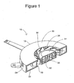
- Cooling system 16 intended for placement inside of a notebook or laptop computer. Cooling system 16 is operable while the notebook computer is in use, to remove or dissipate heat generated by the electrical components.
- the cooling system includes a housing 18 with a top wall 20 and a bottom wall 22 that determine a circular housing profile, and an annular side wall 24.
- a central opening 26 in the top wall, and a similarly sized central opening 28 in the bottom wall, provide opposite side inlets that accommodate the flow of air into the cooling system. Air flow out of the system is accommodated in a known manner by one or more openings through side wall 24, not shown.
- Housing 18 contains an impeller 30 and a motor for rotating the impeller about a vertical impeller axis relative to the housing.
- Components of the motor include stator windings 32 arraigned about the axis and fixed with respect to the housing.
- Impeller 30 includes a central hub 34 mounted on a spindle 36 for rotation about the impeller axis.
- the hub integrally contains several motor components, including a back iron and one or more permanent magnets.
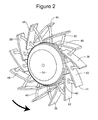
- impeller 30 includes a plurality of impeller blades 38, arranged in a sequence circumferentially about hub 34 for rotation with the hub about the axis.
- Blades 38 have a constant width in the axial direction, about equal to the axial height of hub 34 as perhaps best seen in Figure 1 .
- the blade width may vary, and the axial height of the hub may be considerably more than the axial width of the blades. The blades are longer than they are wide.
- Impeller 30 includes thirteen blades, and in similar versions of the impeller, the number of blades may range from eleven to nineteen.
- a plurality of struts 40 support blades 38 in radially spaced apart relation to hub 34. There is a one-to-one correspondence of struts to blades, in that each blade is supported by two of the struts and each of the struts supports two adjacent blades.
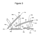
- edges 42a, 42b, and 42c of blades 38a, 38b, and 38c are leading edges with a relatively close radial spacing from hub 34.
- Edges 44a and 44b are trailing edges of blades 38a and 38b, radially more remote from the hub axis.
- Blades 38 are backwardly curved, in the sense that their radial distance from the hub axis progressively increases in the rearward direction.
- blades 38 are positioned to determine a ratio R1/R2 in the range of 0.6 to 0.5, where R1 is the radial spacing of each blade leading edge 42 and R2 is the radial spacing of the blade trailing edge.
- each of blades 38 includes a forward region 46 that encompasses the leading edge, a rearward region 48 encompassing the trailing edge, and a medial region 50 between the forward and rearward regions.
- Each of struts 40 supports two adjacent blades.
- strut 40b is coupled to hub 34, blade 38b along forward region 46b, and to blade 38a along rearward region 48a. In similar fashion, each of the struts supports two adjacent blades.
- each blade is supported by two adjacent struts.
- Blade 38b for example, is supported at its forward region 46b by strut 40b, and supported at its rearward region 48b by strut 40c.
- Impeller 30 preferably is formed as a single piece by injection molding, using an engineered plastic such as glass-filled nylon or a metal such as magnesium. Accordingly, strut 40b "extends through" blade 38b on the way to blade 38a in a functional rather than literal sense. Alternatively, strut 40b might be considered to include a radially inward strut segment mounting blade 38b with respect to hub 34, and a radially outward strut segment mounting blade 38a with respect to blade 38b. In any event, each strut is integrally coupled to the hub, the forward region of an associated strut, and the rearward region of the adjacent associated strut to firmly support the blades in a manner that minimizes distortion and vibration.
- Blades 38 are aerodynamically designed for enhanced air flow through system 16. Each blade has a diverging and converging thickness. More particularly, the thickness increases gradually from leading edge 42 to maximum thickness along medial region 50, then diminishes gradually to a reduced thickness at trailing edge 44. In blades 38, this is accomplished primarily through selective curvature of a positive pressure side 52 and to a lesser extent the curvature of a suction side 54 of the blade.
- the maximum thickness ranges from 1.25 to 1.40 times the thickness at the leading edge. This ratio, combined with the progressive and gradual increase in thickness backwardly from the leading edge, provides optimal efficiency by minimizing separation of airflow across the blade surfaces.
- a selective curvature of positive pressure side 52 can afford the additional advantage of determining or setting the blade inlet angle and blade discharge angle independently of one another.
- the blade inlet angle is the angle between the meanline near the leading edge and a tangent of the hub taken at the leading edge.
- the discharge angle is the angle between the meanline near the blade trailing edge and a tangent of a circle centered on the hub axis with a radius extending to the trailing edge.
- the inlet angle ranges from 22 degrees to 30 degrees
- the discharge angle ranges from 44 degrees to 52 degrees.
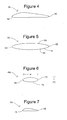
- Figure 4 and 5 illustrate alternative blade thickness profiles.
- an impeller blade 56 exhibits a more pronounced increase in thickness from a leading edge 58 to a maximum thickness near a forward end of its medial region, followed by a more gradual reduction in thickness to a trailing edge 60.
- both the increase and decrease in thickness can be characterized as "gradual.”
- an impeller blade 62 is curved along its positive pressure side 64 and its leeward side 66 to provide the desired divergence and convergence between a leading edge 63 and a trailing edge 65.
- the opposite sides in Figure 5 can be symmetrical about a bisecting plane.
- Figure 6 illustrates the profile of strut 40c in a plane substantially perpendicular to the strut length, to illustrate the strut thickness profile.
- the strut has a width w substantially in the circumferential direction.
- the strut thickness t, perpendicular to the width, is considerably less than the strut width, and varies in diverging/converging fashion. That is, the thickness increases gradually from a forward edge 68 of a strut to point 70 of maximum thickness in a medial region of the strut, then is reduced gradually to a reduced thickness at a rearward edge 72 of the strut.
- Figure 7 illustrates an alternative strut 74 with forward and rearward edges 73 and 75, featuring a relatively steep divergence in thickness followed by a relatively gradual convergence. As noted above with respect to the blades, the divergence and convergence in strut thickness are both gradual in the broad sense of avoiding abrupt changes.
- FIG 8 illustrates an alternative embodiment impeller 76 with a hub 78, a plurality of impeller blades 80, and a plurality of struts 82 for supporting the impeller blades in a circumferential sequence about the hub in spaced apart relation to the hub.
- Impeller 76 differs from impeller 30 in that struts 82 are rearwardly curved instead of forwardly curved as they extend primarily radially away from the hub.
- FIG. 9 illustrates another alternative embodiment impeller 84 in which blades 86 are supported spaced apart from a hub 88 by struts 90. Blades 86 are forwardly curved, in contrast to backwardly curved blades 38 and 80. In this embodiment, the remote edges of blades 86 are the leading edges, while the proximate edges are the trailing edges.
- FIG 10 illustrates a further embodiment impeller 92 in which backwardly curved impeller blades 94a-c are supported in spaced apart relation to a hub 96 by struts 98a-c and 99a-c.
- struts 98 and 99 are circumferentially offset from one another.
- shorter strut 90a is coupled to hub 96 and to blade 94a near its leading and proximate edge.
- Longer strut 99a is coupled to blade 94a near its trailing and remote edge, and further is coupled to blade 94b at a medial location between the locations along the blade at which struts 98b and 99b are coupled.
- strut 99a can be coupled to blade 94a at a point nearer to a trailing edge 100a.
- the struts are centered on a reference plane (not illustrated) passing through the hub and perpendicular to the hub axis. More preferably, the reference plane is axially centered with respect to the hub.
- the struts are staggered to position adjacent struts on opposite sides the reference plane. The staggered arrangements require an even number of struts, and thus require an even number of blades in arrangements featuring a one-to-one correspondence of struts to blades. Staggered struts may be parallel to or inclined relative to the reference plane.
- Impellers designed in accordance with the present invention are more efficient in terms of the air power output generated in response to a given level of input power.
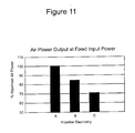
- Figure 11 is a chart illustrating different levels of air power output at a fixed input power for several impeller designs.
- a second impeller was like the first in that its blades were of constant thickness and their leading edges were contiguous with the hub. This impeller differed from the first in that its blades were backwardly curved. This design is represented by the bar labeled "B" in the chart.
- the final impeller represented by the bar labeled "A," also had backwardly curved blades.
- the thickness of the blades varied gradually between a maximum thickness along a medial region of the blade and reduced thicknesses near the blade leading and trailing edges. Further, the leading edges of the blades were spaced apart radially from the hub, supported relative to the hub by aerodynamically designed struts.
- a comparison of the bars B and C in Figure 11 illustrates the improvement in efficiency that results simply from introducing curvature in the impeller blades.
- Comparison of bar A with bar B illustrates the considerable further improvement in efficiency achieved by separating the blade leading edges from the hub to allow airflow through a radial gap between each blade and the hub, and by selectively varying the blade thickness to improve aerodynamics and independently control curvature along the positive pressure surface and the suction surface of the blade.
- the improved impeller is capable of removing more excess heat at a given input power level, or alternatively producing the same cooling effect at a reduced input power level.
- an impeller for a centrifugal fan is improved structurally and aerodynamically for moving more air through a cooling system at higher speeds.
- the impeller blades are supported in spaced apart relation to the hub at locations proximate but recessed from the blade leading and trailing edges, to provide a favorable combination of smoother air flow and increased stability.
- Multiple strut-to-blade couplings enable the use of smaller, lighter weight struts to provide the desired stability. Aerodynamically designed struts further enhance airflow.
Landscapes
- Engineering & Computer Science (AREA)
- Mechanical Engineering (AREA)
- General Engineering & Computer Science (AREA)
- Physics & Mathematics (AREA)
- Geometry (AREA)
- Structures Of Non-Positive Displacement Pumps (AREA)
Abstract
Description
- This application claims the benefit of priority based on Provisional Application No.
61/242,853 - The present invention relates to cooling systems for computers and other electronic devices, and more particularly to low-profile, compact centrifugal air impellers designed to operate at high speeds.
- Designers of a wide variety of electronic devices continually strive to provide more utility in smaller packages. Notebook or laptop computers illustrate this trend, in terms of the ongoing efforts to reduce their size and at the same time enlarge their capacity and capability to store and manipulate data. These devices generate heat during use, with increased functionality leading to increased heat generation. Failure to remove excess heat subjects these devices to a variety of risks ranging from reduced efficiency to serious and permanent damage.
- Thus, designers of cooling systems for these devices face the dual and competing goals of smaller size and increased capacity for removing heat.
- Typically, notebook computers have been designed to incorporate an internal housing or compartment for a dual-inlet, centrifugal type fan. In one conventional design, blades of constant thickness are attached directly to a rotor hub at their leading edges and extend away from the hub in "backwardly-inclined" fashion. This design can be molded with relative ease at low cost, but entails several disadvantages that become more pronounced in a reduced size, higher speed environment. One is the lack of an aerodynamically effective approach to drawing air into the blades. High speeds lead to distortion of the blades, further reducing efficiency and generating unwanted noise.
- Efforts to solve these problems have lead to designs featuring structural or guide members along the blades, either on the positive pressure side as in
U.S. patent application, Publication No. 2008/0130226 (Yamashita et al. ), or on the leeward side as inU.S. patent application, Publication No. 2009/0028710 (Horng et al. ). Another known approach involves selectively varying the blade thickness as shown inU.S. Patent No. 6,579,064 (Hsieh ) andU.S. Patent No. 7,118,345 (Wu et al. ). - In yet another approach the blades, particularly including their leading edges, are separated from the primary hub structure. This has been accomplished with an angular plate extending from the hub as shown in
U.S. Patent No. 6,568,907 (Horng et al. ), or with a ring supported radially outwardly from the hub, as inU.S patent application, Publication No. 2008/0226446 (Fujieda ) and the aforementioned Wu patent. - Yet another approach is to support the blades individually with posts or other members at their leading edges. Examples of this approach include
U.S. Patent No. 7,063,510 (Takeshita et al. ) andU.S. patent application, Publication No. 2007/0274834 (Huang et al. ). - Although the forgoing examples and similar approaches have led to improved performance compared to the directly attached linear constant thickness blade design, the above-identified problems persist. Accordingly, the present invention is characterized by several aspects directed to one or more of the following objects:
- to provide an impeller with a mounting structure that locates the impeller blades in spaced apart relation to a hub while providing more stable support for the blades;
- to provide an impeller including a plurality of struts for supporting a plurality of impeller blades in surrounding, spaced apart relation to a hub in a manner that provides positive support to each blade at forward and rearward regions thereof, for improved stability;
- to provide, in a centrifugal fan impeller, impeller blades and blade-supporting struts with profiles shaped for improved aerodynamic efficiency; and
- to provide an impeller construction that facilitates independent optimization of blade inlet and discharge angles.
- To achieve these and other objects, there is provided a centrifugal impeller. The centrifugal impeller includes a hub rotatable on a hub axis and having a hub outer periphery disposed circumferentially about the hub axis. The impeller further includes a plurality of blades. A blade mounting structure, narrower axially than the blades, supports the blades integrally relative to the hub and spaced apart from the hub in a circumferential sequence about the hub for rotation with the hub about the hub axis in a forward direction. This determines in each blade a leading edge and a trailing edge. The blade mounting structure further supports the blades inclined relative to the hub. This selects one of the leading and trailing edges as a proximate edge spaced radially from the hub outer periphery by a first distance, and selects the other of the leading and trailing edges as a remote edge spaced radially from the hub outer periphery by a second distance greater than the first distance. The blade mounting structure comprises a plurality of first structural segments coupled with respect to the hub and associated individually with the blades. Each first structural segment is coupled to its associated blade at a first location near the proximate edge. The blade mounting structure further comprises a plurality of second structural segments associated individually with adjacent pairs of the blades. Each second structural segment is coupled to a first blade of its associated pair at a second location between the first location and the remote edge, and further is coupled to a second blade of the associated pair to couple said first and second blades.
- The impeller features a blade mounting structure that supports each blade with structural segments at two locations, a first location near the proximate edge and a second location between the first location and the remote edge. Two spaced apart structural segments, preferably struts, replace a single, massive blade mounting structure. Accordingly, the advantages of increased stability and more aerodynamically effective air flow can be achieved as compared to the single blade mounting structure. To further improve air flow, the first and second locations can be recessed from the proximate edge and remote edge, respectively. This leaves portions of the forward and rearward blade edges with smooth profiles uninterrupted by the struts, to promote a more laminar and less turbulent air flow.
- In one version of the impeller, the second structural segment is coupled to the second blade of the associated pair at a location that coincides with the first location. The second structural segment and its associated first structural segment are aligned end to end, and resemble a single strut extending from the hub and through the second blade toward a point of attachment to the first blade. In an alternative version of the impeller, the second structural segment is coupled to the second blade at a third location disposed between the first location and the second location.
- In preferred versions of the impeller, the blades are backwardly curved. In these versions, the proximate edge of each blade is the leading edge, and the remote edge is the trailing edge. Nonetheless, the principles of the invention can be applied to impellers with forwardly curved blades to achieve similar advantages.
- The structural segments preferably comprise blade-supporting struts. In one preferred arrangement with backwardly curved blades, each strut is coupled to the hub periphery, to the rearward region of a first one of the blades associated with the strut, and to the forward region of a second blade associated with the strut. The second blade immediately follows the first blade in the sequence. Each strut includes a radially inward section between the hub and the second blade, and a radially outward section between the first and second blades. The strut sections are aligned end to end to provide the appearance and function of a single strut.
- This arrangement provides the combination of two-point anchoring of each blade and a one-to-one correspondence of struts to blades. Securing each blade at its forward region and at its rearward region reduces blade distortion and vibration. This is advantageous in any event and particularly at high speeds. For example, while conventional centrifugal fans of this kind typically are operated at rotational speeds up to 5,000 RPM (revolutions per minute), fans with two-point anchoring pursuant to the present invention can be operated at speeds up to 10,000 RPM with minimal blade distortion. Supporting each blade with two struts rather than one allows the use of reduced profile, lighter weight struts. Each pair of struts supporting a blade can have a combined mass comparable to a single strut in prior designs. Smaller struts with more aerodynamic profiles lead to less turbulent flow across the blade surfaces. For selective placement of strut-to-blade coupling locations, the struts can be curved forwardly or rearwardly in a generally radial direction of extension away from the hub.
- Each of the blades preferably has a constant blade width in the axial direction. A blade thickness, generally in the radial direction, varies gradually between a first thickness proximate the leading edge and a second thickness along a medial region of the blade. The blade thickness further varies gradually between the second thickness and a third thickness proximate the trailing edge. Each of the first and third thicknesses is less than the second thickness. Further in preferred versions, each of the struts has a circumferential width, and an axial thickness less than the width that varies gradually between a maximum thickness along a medial portion of a strut and reduced thicknesses at forward and rearward edge portions of the strut.
- The blades and the struts accordingly have thickness profiles that diverge from a forward edge to a maximum thickness along a medial region or midportion, then converge to a reduced thickness at a rearward edge. This promotes a smoother, more laminar air flow in the rearward direction along the blades and struts. The profiles can be curved on one side, curved on both sides, or substantially identically curved on both sides to be symmetrical about a bisecting plane. In a particularly preferred version, the thickness of the blades is controlled to provide a maximum thickness along the medial region ranging from 1.25 to 1.40 times the blade thickness at the leading edge.
- Thus in accordance with the present invention, a centrifugal impeller locates the impeller blades spaced apart from the hub in a secure, stable fashion to minimize distortion and vibration at high speeds, and with considerably improved aerodynamic performance for more effective heat dissipation.
- For a further understanding of the above and other features, reference is made to the following detailed description and to the drawings, in which:
-
Figure 1 is a partial, sectioned view of a convective cooling system constructed in accordance with the present invention; -
Figure 2 is an isometric view showing an air impeller of the cooling system; -
Figure 3 is an enlarged partial, top plan view of the impeller; -
Figures 4 and 5 show alternative impeller blade thickness profiles; -
Figure 6 is a sectional view taken along the line 6-6 inFigure 3 ; -
Figure 7 schematically illustrates an alternative strut thickness profile; -
Figure 8 is an isometric view showing an alternative embodiment impeller; -
Figure 9 is a schematic view showing part of another alternative embodiment impeller; -
Figure 10 is a schematic view showing part of a further alternative embodiment impeller; and -
Figure 11 is a chart comparing air power output for different impeller designs. - Turning now to the drawings, there is shown in
Figure 1 aconvective cooling system 16 intended for placement inside of a notebook or laptop computer.Cooling system 16 is operable while the notebook computer is in use, to remove or dissipate heat generated by the electrical components. - The cooling system includes a
housing 18 with atop wall 20 and abottom wall 22 that determine a circular housing profile, and anannular side wall 24. Acentral opening 26 in the top wall, and a similarly sizedcentral opening 28 in the bottom wall, provide opposite side inlets that accommodate the flow of air into the cooling system. Air flow out of the system is accommodated in a known manner by one or more openings throughside wall 24, not shown. -
Housing 18 contains animpeller 30 and a motor for rotating the impeller about a vertical impeller axis relative to the housing. Components of the motor includestator windings 32 arraigned about the axis and fixed with respect to the housing.Impeller 30 includes acentral hub 34 mounted on aspindle 36 for rotation about the impeller axis. The hub integrally contains several motor components, including a back iron and one or more permanent magnets. - As seen in
Figure 2 ,impeller 30 includes a plurality ofimpeller blades 38, arranged in a sequence circumferentially abouthub 34 for rotation with the hub about the axis.Blades 38 have a constant width in the axial direction, about equal to the axial height ofhub 34 as perhaps best seen inFigure 1 . In alternative impeller configurations, the blade width may vary, and the axial height of the hub may be considerably more than the axial width of the blades. The blades are longer than they are wide.Impeller 30 includes thirteen blades, and in similar versions of the impeller, the number of blades may range from eleven to nineteen. - A plurality of
struts 40support blades 38 in radially spaced apart relation tohub 34. There is a one-to-one correspondence of struts to blades, in that each blade is supported by two of the struts and each of the struts supports two adjacent blades. - As indicated by the arrow in
Figure 2 ,impeller 30 rotates about the axis in the counterclockwise direction. Thus, with reference toFigure 3 ,edges blades hub 34.Edges blades Blades 38 are backwardly curved, in the sense that their radial distance from the hub axis progressively increases in the rearward direction. In terms of radial spacing from the center ofhub 34,blades 38 are positioned to determine a ratio R1/R2 in the range of 0.6 to 0.5, where R1 is the radial spacing of eachblade leading edge 42 and R2 is the radial spacing of the blade trailing edge. - With further reference to
Figure 3 , each ofblades 38 includes aforward region 46 that encompasses the leading edge, arearward region 48 encompassing the trailing edge, and amedial region 50 between the forward and rearward regions. Each ofstruts 40 supports two adjacent blades. For example,strut 40b is coupled tohub 34,blade 38b alongforward region 46b, and toblade 38a along rearwardregion 48a. In similar fashion, each of the struts supports two adjacent blades. - Likewise, each blade is supported by two adjacent struts.
Blade 38b, for example, is supported at itsforward region 46b bystrut 40b, and supported at itsrearward region 48b bystrut 40c. -
Impeller 30 preferably is formed as a single piece by injection molding, using an engineered plastic such as glass-filled nylon or a metal such as magnesium. Accordingly, strut 40b "extends through"blade 38b on the way toblade 38a in a functional rather than literal sense. Alternatively,strut 40b might be considered to include a radially inward strutsegment mounting blade 38b with respect tohub 34, and a radially outward strutsegment mounting blade 38a with respect toblade 38b. In any event, each strut is integrally coupled to the hub, the forward region of an associated strut, and the rearward region of the adjacent associated strut to firmly support the blades in a manner that minimizes distortion and vibration. -
Blades 38 are aerodynamically designed for enhanced air flow throughsystem 16. Each blade has a diverging and converging thickness. More particularly, the thickness increases gradually from leadingedge 42 to maximum thickness alongmedial region 50, then diminishes gradually to a reduced thickness at trailingedge 44. Inblades 38, this is accomplished primarily through selective curvature of apositive pressure side 52 and to a lesser extent the curvature of asuction side 54 of the blade. - In preferred versions of
blade 38, the maximum thickness ranges from 1.25 to 1.40 times the thickness at the leading edge. This ratio, combined with the progressive and gradual increase in thickness backwardly from the leading edge, provides optimal efficiency by minimizing separation of airflow across the blade surfaces. - A selective curvature of
positive pressure side 52 can afford the additional advantage of determining or setting the blade inlet angle and blade discharge angle independently of one another. The blade inlet angle is the angle between the meanline near the leading edge and a tangent of the hub taken at the leading edge. The discharge angle is the angle between the meanline near the blade trailing edge and a tangent of a circle centered on the hub axis with a radius extending to the trailing edge. As an example, in preferred versions of the impeller the inlet angle ranges from 22 degrees to 30 degrees, and the discharge angle ranges from 44 degrees to 52 degrees. -
Figure 4 and 5 illustrate alternative blade thickness profiles. Infigure 4 , animpeller blade 56 exhibits a more pronounced increase in thickness from a leadingedge 58 to a maximum thickness near a forward end of its medial region, followed by a more gradual reduction in thickness to a trailingedge 60. In the broader sense of providing smooth transitions without abrupt changes, both the increase and decrease in thickness can be characterized as "gradual." InFigure 5 , animpeller blade 62 is curved along itspositive pressure side 64 and itsleeward side 66 to provide the desired divergence and convergence between aleading edge 63 and a trailingedge 65. The opposite sides inFigure 5 can be symmetrical about a bisecting plane. -
Figure 6 illustrates the profile ofstrut 40c in a plane substantially perpendicular to the strut length, to illustrate the strut thickness profile. The strut has a width w substantially in the circumferential direction. The strut thickness t, perpendicular to the width, is considerably less than the strut width, and varies in diverging/converging fashion. That is, the thickness increases gradually from aforward edge 68 of a strut to point 70 of maximum thickness in a medial region of the strut, then is reduced gradually to a reduced thickness at arearward edge 72 of the strut. -
Figure 7 illustrates analternative strut 74 with forward and rearward edges 73 and 75, featuring a relatively steep divergence in thickness followed by a relatively gradual convergence. As noted above with respect to the blades, the divergence and convergence in strut thickness are both gradual in the broad sense of avoiding abrupt changes. -
Figure 8 illustrates analternative embodiment impeller 76 with ahub 78, a plurality ofimpeller blades 80, and a plurality ofstruts 82 for supporting the impeller blades in a circumferential sequence about the hub in spaced apart relation to the hub.Impeller 76 differs fromimpeller 30 in that struts 82 are rearwardly curved instead of forwardly curved as they extend primarily radially away from the hub. -
Figure 9 illustrates anotheralternative embodiment impeller 84 in whichblades 86 are supported spaced apart from ahub 88 bystruts 90.Blades 86 are forwardly curved, in contrast to backwardlycurved blades blades 86 are the leading edges, while the proximate edges are the trailing edges. -
Figure 10 illustrates afurther embodiment impeller 92 in which backwardlycurved impeller blades 94a-c are supported in spaced apart relation to ahub 96 bystruts 98a-c and 99a-c. As compared to the struts in previous versions, struts 98 and 99 are circumferentially offset from one another. For example, shorter strut 90a is coupled tohub 96 and toblade 94a near its leading and proximate edge.Longer strut 99a is coupled toblade 94a near its trailing and remote edge, and further is coupled toblade 94b at a medial location between the locations along the blade at which struts 98b and 99b are coupled. This doubles the ratio of struts to blades, but affords more flexibility in terms of placing the struts with respect to the blades. More particularly, because it is offset rather than aligned end to end withstrut 98b,strut 99a can be coupled toblade 94a at a point nearer to atrailing edge 100a. - In the preferred impeller, the struts are centered on a reference plane (not illustrated) passing through the hub and perpendicular to the hub axis. More preferably, the reference plane is axially centered with respect to the hub. In alternative impellers, the struts are staggered to position adjacent struts on opposite sides the reference plane. The staggered arrangements require an even number of struts, and thus require an even number of blades in arrangements featuring a one-to-one correspondence of struts to blades. Staggered struts may be parallel to or inclined relative to the reference plane.
- Impellers designed in accordance with the present invention are more efficient in terms of the air power output generated in response to a given level of input power.
Figure 11 is a chart illustrating different levels of air power output at a fixed input power for several impeller designs. - Three different impellers were tested in the same system. One of the impellers was a conventional design in which the impeller blades were linear and of constant thickness. The blades were backwardly inclined. The blades were attached directly to the hub, with their leading edges contiguous with the hub. This design is represented by the bar labeled "C" in
Figure 11 . - A second impeller was like the first in that its blades were of constant thickness and their leading edges were contiguous with the hub. This impeller differed from the first in that its blades were backwardly curved. This design is represented by the bar labeled "B" in the chart.
- The final impeller, represented by the bar labeled "A," also had backwardly curved blades. In accordance with the present invention, the thickness of the blades varied gradually between a maximum thickness along a medial region of the blade and reduced thicknesses near the blade leading and trailing edges. Further, the leading edges of the blades were spaced apart radially from the hub, supported relative to the hub by aerodynamically designed struts.
- A comparison of the bars B and C in
Figure 11 illustrates the improvement in efficiency that results simply from introducing curvature in the impeller blades. Comparison of bar A with bar B illustrates the considerable further improvement in efficiency achieved by separating the blade leading edges from the hub to allow airflow through a radial gap between each blade and the hub, and by selectively varying the blade thickness to improve aerodynamics and independently control curvature along the positive pressure surface and the suction surface of the blade. Thus, the improved impeller is capable of removing more excess heat at a given input power level, or alternatively producing the same cooling effect at a reduced input power level. - In accordance with the present invention, an impeller for a centrifugal fan is improved structurally and aerodynamically for moving more air through a cooling system at higher speeds. The impeller blades are supported in spaced apart relation to the hub at locations proximate but recessed from the blade leading and trailing edges, to provide a favorable combination of smoother air flow and increased stability. Multiple strut-to-blade couplings enable the use of smaller, lighter weight struts to provide the desired stability. Aerodynamically designed struts further enhance airflow.
Claims (15)
- A centrifugal impeller, including:a hub rotatable on a hub axis and having a hub outer periphery disposed circumferentially about the hub axis;a plurality of blades; anda blade mounting structure, narrower axially than the blades, supporting the blades integrally relative to the hub and spaced apart from the hub in a circumferential sequence about the hub for rotation with the hub about the hub axis in a forward direction to determine in each blade a leading edge and a trailing edge, the blade mounting structure further supporting the blades inclined relative to the hub to select one of the leading and trailing edges as a proximate edge spaced radially from the hub outer periphery by a first distance and to select the other of said leading and trailing edges as a remote edge spaced radially from the hub outer periphery by a second distance greater than the first distance;wherein the blade mounting structure comprises a plurality of first structural segments coupled with respect to the hub and associated individually with the blades, with each first structural segment coupled to its associated blade at a first location near the proximate edge, the blade mounting structure further comprising a plurality of second structural segments associated individually with adjacent pairs of the blades, each second structural segment coupled to a first blade of its associated pair at a second location between the first location and the remote edge and coupled to a second blade of the associated pair to couple the first and second blades.
- The impeller of Claim 1 wherein:the first location of each of the blades is recessed from the proximate edge, and the second location of each blade is recessed from the remote edge.
- The impeller of Claim 1 or Claim 2, wherein:the blades are backwardly curved, thereby to select in each blade the leading edge as the proximate edge and the trailing edge as the remote edge.
- The impeller of Claim 3 wherein:each of the blades comprises a forward region encompassing the leading edge, a rearward region encompassing the trailing edge, and a medial region between the forward region and the rearward region, wherein a thickness of the blade varies gradually between a first thickness proximate the leading edge and a second thickness along the medial region, and the second thickness is in the range from 1.25 to 1.40 times the first thickness.
- The impeller of Claim 4 wherein:the thickness of each of the blades further varies gradually between the second thickness and a third thickness proximate the trailing edge, and the third thickness is less than the second thickness.
- The impeller of Claim 1 or Claim 2, wherein:the blades are forwardly curved, thereby to select in each blade the leading edge as the remote edge and the trailing edge as the proximate edge.
- The impeller of any preceding claim further including:a stationary housing surrounding the hub and blade and defining air inlet passages on opposite sides of the hub near the hub axis;a motor stator integral with the housing and disposed about the hub axis; anda rotor integral with the hub and disposed about the hub axis.
- The impeller of any preceding claim, wherein:the first and second structural segments comprise struts, each strut having a circumferential width and an axial thickness that is less than the width and varies gradually between a maximum thickness along a medial portion of the strut and reduced thicknesses at forward and rearward edge portions of the strut.
- The impeller of Claim 8 wherein:the struts are curved forwardly in the direction of radial extension away from the hub.
- The impeller of Claim 8 or Claim 9 wherein:the struts are substantially equally spaced about the hub.
- The impeller of any of Claims 8 to 10 wherein:each of the struts is substantially centered with respect to a plane perpendicular to the hub axis.
- The impeller of any preceding claim wherein:each of the second structural segments is coupled to the second blade of its associated pair at a location that coincides with the first location.
- The impeller of any of Claims 1 to 11 wherein:each of the second structural segments is coupled to the second blade of its associated pair at a third location disposed between the first location and the second location.
- The impeller of any preceding claim wherein:the blades have a substantially constant width in the axial direction.
- The impeller of any preceding claim wherein:the plurality of blades consists essentially of a number of blades selected from 11, 12, 13, 14, 15, 16, 17, 18 and 19.
Applications Claiming Priority (1)
| Application Number | Priority Date | Filing Date | Title |
|---|---|---|---|
| US24285309P | 2009-09-16 | 2009-09-16 |
Publications (3)
| Publication Number | Publication Date |
|---|---|
| EP2336573A2 true EP2336573A2 (en) | 2011-06-22 |
| EP2336573A3 EP2336573A3 (en) | 2017-11-29 |
| EP2336573B1 EP2336573B1 (en) | 2019-04-17 |
Family
ID=43730740
Family Applications (1)
| Application Number | Title | Priority Date | Filing Date |
|---|---|---|---|
| EP10176921.4A Not-in-force EP2336573B1 (en) | 2009-09-16 | 2010-09-15 | High efficiency low-profile centrifugal fan |
Country Status (2)
| Country | Link |
|---|---|
| US (1) | US8647051B2 (en) |
| EP (1) | EP2336573B1 (en) |
Cited By (1)
| Publication number | Priority date | Publication date | Assignee | Title |
|---|---|---|---|---|
| US11913355B2 (en) | 2022-02-14 | 2024-02-27 | General Electric Company | Part-span shrouds for pitch controlled aircrafts |
Families Citing this family (9)
| Publication number | Priority date | Publication date | Assignee | Title |
|---|---|---|---|---|
| AU341644S (en) * | 2011-12-23 | 2012-03-28 | Smallaire Pty Ltd | Blower impeller |
| TWI504812B (en) * | 2012-02-20 | 2015-10-21 | Quanta Comp Inc | Centrifugal fan |
| US8961107B2 (en) * | 2012-05-17 | 2015-02-24 | Adda Corp. | Heat-dissipation fan |
| CN107956742A (en) * | 2017-05-27 | 2018-04-24 | 莱克电气股份有限公司 | A kind of impeller assembly and air purifier |
| CN108144471B (en) * | 2018-02-22 | 2024-01-16 | 中国恩菲工程技术有限公司 | Combined rotor impeller and flotation machine |
| CN108678993A (en) * | 2018-04-23 | 2018-10-19 | 国泰达鸣精密机件(深圳)有限公司 | A kind of high rotating speed blade wheel structure and its processing method |
| TWI707088B (en) * | 2019-08-13 | 2020-10-11 | 大陸商昆山廣興電子有限公司 | Impeller |
| CN112343858B (en) * | 2020-11-17 | 2024-12-10 | 昆山品岱电子有限公司 | A low-noise cicada-wing fan blade |
| WO2024057935A1 (en) * | 2022-09-16 | 2024-03-21 | 株式会社Megaderu | Rotary wing |
Citations (7)
| Publication number | Priority date | Publication date | Assignee | Title |
|---|---|---|---|---|
| US6568907B2 (en) | 2001-09-28 | 2003-05-27 | Sunonwealth Electric Machine Industry Co., Ltd. | Impeller structure |
| US6579064B2 (en) | 2001-10-01 | 2003-06-17 | Hsieh Hsin-Mao | Blade for a cooling fan |
| US7063510B2 (en) | 2003-09-17 | 2006-06-20 | Nidec Corporation | Centrifugal fan |
| US7118345B2 (en) | 2003-06-20 | 2006-10-10 | Delta Electronics, Inc. | Fan blade |
| US20070274834A1 (en) | 2006-05-26 | 2007-11-29 | Delta Electronics Inc. | Rotor and manufacturing method thereof |
| US20080130226A1 (en) | 2006-11-30 | 2008-06-05 | Matsushita Electric Industrial Co., Ltd. | Centrifugal fan device and electronic apparatus having the same |
| US20090028710A1 (en) | 2007-07-26 | 2009-01-29 | Sunonwealth Electric Machine Industry Co., Ltd. | Fan blade |
Family Cites Families (18)
| Publication number | Priority date | Publication date | Assignee | Title |
|---|---|---|---|---|
| US65252A (en) * | 1867-05-28 | Improved paddle-wheel | ||
| US195865A (en) * | 1877-10-02 | Improvement in fan-blowers | ||
| US1779026A (en) * | 1928-04-12 | 1930-10-21 | Wragg Charles Arthur | Multiple-blade propeller |
| US2431648A (en) * | 1945-02-09 | 1947-11-25 | Robert A Mayne | Blower |
| DE2117387A1 (en) * | 1970-04-13 | 1971-11-04 | Mini Of Aviat Supply | Bladed rotor for a gas turbine jet engine |
| US4326836A (en) * | 1979-12-13 | 1982-04-27 | United Technologies Corporation | Shroud for a rotor blade |
| US6206641B1 (en) * | 1998-06-29 | 2001-03-27 | Samsung Electro-Mechanics Co., Ltd. | Micro fan |
| US6345956B1 (en) * | 1998-07-14 | 2002-02-12 | Delta Electronics, Inc. | Impeller of a blower having air-guiding ribs with geometrical configurations |
| KR100405207B1 (en) * | 2000-12-19 | 2003-11-12 | 삼성전기주식회사 | Micro fan |
| USD486569S1 (en) * | 2003-05-05 | 2004-02-10 | Delta Electronics, Inc. | Fan blade |
| JP2004353496A (en) * | 2003-05-28 | 2004-12-16 | Sony Corp | Thin fan motor |
| TWI281847B (en) * | 2004-05-07 | 2007-05-21 | Delta Electronics Inc | Fan |
| US8202055B2 (en) * | 2004-05-07 | 2012-06-19 | Delta Electronics, Inc. | Fan and impeller |
| US20070065279A1 (en) * | 2005-09-20 | 2007-03-22 | Chih-Cheng Lin | Blade structure for a radial airflow fan |
| JP5140986B2 (en) * | 2006-03-15 | 2013-02-13 | 株式会社デンソー | Centrifugal multi-blade fan |
| CN100478572C (en) * | 2006-10-13 | 2009-04-15 | 林钧浩 | Pressurized centrifugan blower impeller |
| JP4432989B2 (en) * | 2007-03-16 | 2010-03-17 | ソニー株式会社 | Centrifugal impeller, fan device and electronic equipment |
| USD587363S1 (en) * | 2008-07-18 | 2009-02-24 | Martin Rheault | Impeller for a small device air blower fan |
-
2010
- 2010-09-07 US US12/876,619 patent/US8647051B2/en active Active
- 2010-09-15 EP EP10176921.4A patent/EP2336573B1/en not_active Not-in-force
Patent Citations (7)
| Publication number | Priority date | Publication date | Assignee | Title |
|---|---|---|---|---|
| US6568907B2 (en) | 2001-09-28 | 2003-05-27 | Sunonwealth Electric Machine Industry Co., Ltd. | Impeller structure |
| US6579064B2 (en) | 2001-10-01 | 2003-06-17 | Hsieh Hsin-Mao | Blade for a cooling fan |
| US7118345B2 (en) | 2003-06-20 | 2006-10-10 | Delta Electronics, Inc. | Fan blade |
| US7063510B2 (en) | 2003-09-17 | 2006-06-20 | Nidec Corporation | Centrifugal fan |
| US20070274834A1 (en) | 2006-05-26 | 2007-11-29 | Delta Electronics Inc. | Rotor and manufacturing method thereof |
| US20080130226A1 (en) | 2006-11-30 | 2008-06-05 | Matsushita Electric Industrial Co., Ltd. | Centrifugal fan device and electronic apparatus having the same |
| US20090028710A1 (en) | 2007-07-26 | 2009-01-29 | Sunonwealth Electric Machine Industry Co., Ltd. | Fan blade |
Cited By (1)
| Publication number | Priority date | Publication date | Assignee | Title |
|---|---|---|---|---|
| US11913355B2 (en) | 2022-02-14 | 2024-02-27 | General Electric Company | Part-span shrouds for pitch controlled aircrafts |
Also Published As
| Publication number | Publication date |
|---|---|
| EP2336573B1 (en) | 2019-04-17 |
| US8647051B2 (en) | 2014-02-11 |
| EP2336573A3 (en) | 2017-11-29 |
| US20110064570A1 (en) | 2011-03-17 |
Similar Documents
| Publication | Publication Date | Title |
|---|---|---|
| EP2336573B1 (en) | High efficiency low-profile centrifugal fan | |
| US6663342B2 (en) | Composite heat-dissipating system and its used fan guard with additional supercharging function | |
| EP0761979B1 (en) | Axial flow fan | |
| CN212407116U (en) | Fan wheel and cooling fan with same | |
| US5996685A (en) | Axial flow fan | |
| CN106030119A (en) | Fan comprising an impeller with blades | |
| WO2002038962A2 (en) | High-efficiency, inflow-adapted, axial-flow fan | |
| CN202381399U (en) | Centrifugal fan | |
| CN104847692A (en) | Shrouded fan impeller with reduced cover overlap | |
| JPWO2018008390A1 (en) | Sawtooth fan blade and axial fan and centrifugal fan comprising the fan blade | |
| CN104214139B (en) | fan | |
| WO1990009525A1 (en) | Centrifugal fan with variably cambered blades | |
| KR20130111458A (en) | Axial-flow fan | |
| US7959413B2 (en) | Fan and impeller thereof | |
| WO2008154793A1 (en) | An elecronic chip heat disspition fan | |
| CN103807189A (en) | Turbine fan and display card with same | |
| CN204783822U (en) | Centrifugal aerator | |
| CN216134322U (en) | Air cooling structure, disc type motor and aircraft | |
| JP2015031277A (en) | Impeller for electric blower | |
| JP2010037952A (en) | Impeller for centrifugal compressor | |
| EP1619393B1 (en) | Fan assembly and fan frame thereof | |
| JP2009197593A (en) | Fan device | |
| CN110307178A (en) | A kind of low-noise impeller | |
| US20070009353A1 (en) | Airflow generating structure and the apparatus thereof | |
| CN209398631U (en) | One kind having combined type impeller ventilation blower and its combined type impeller |
Legal Events
| Date | Code | Title | Description |
|---|---|---|---|
| PUAI | Public reference made under article 153(3) epc to a published international application that has entered the european phase |
Free format text: ORIGINAL CODE: 0009012 |
|
| AK | Designated contracting states |
Kind code of ref document: A2 Designated state(s): AL AT BE BG CH CY CZ DE DK EE ES FI FR GB GR HR HU IE IS IT LI LT LU LV MC MK MT NL NO PL PT RO SE SI SK SM TR |
|
| AX | Request for extension of the european patent |
Extension state: BA ME RS |
|
| RAP1 | Party data changed (applicant data changed or rights of an application transferred) |
Owner name: HENKEL IP & HOLDING GMBH |
|
| PUAL | Search report despatched |
Free format text: ORIGINAL CODE: 0009013 |
|
| AK | Designated contracting states |
Kind code of ref document: A3 Designated state(s): AL AT BE BG CH CY CZ DE DK EE ES FI FR GB GR HR HU IE IS IT LI LT LU LV MC MK MT NL NO PL PT RO SE SI SK SM TR |
|
| AX | Request for extension of the european patent |
Extension state: BA ME RS |
|
| RIC1 | Information provided on ipc code assigned before grant |
Ipc: F04D 29/32 20060101ALI20171020BHEP Ipc: F04D 29/30 20060101ALI20171020BHEP Ipc: F04D 29/22 20060101AFI20171020BHEP Ipc: F04D 29/28 20060101ALI20171020BHEP Ipc: F04D 29/38 20060101ALI20171020BHEP |
|
| STAA | Information on the status of an ep patent application or granted ep patent |
Free format text: STATUS: REQUEST FOR EXAMINATION WAS MADE |
|
| 17P | Request for examination filed |
Effective date: 20180322 |
|
| RBV | Designated contracting states (corrected) |
Designated state(s): AL AT BE BG CH CY CZ DE DK EE ES FI FR GB GR HR HU IE IS IT LI LT LU LV MC MK MT NL NO PL PT RO SE SI SK SM TR |
|
| GRAP | Despatch of communication of intention to grant a patent |
Free format text: ORIGINAL CODE: EPIDOSNIGR1 |
|
| STAA | Information on the status of an ep patent application or granted ep patent |
Free format text: STATUS: GRANT OF PATENT IS INTENDED |
|
| INTG | Intention to grant announced |
Effective date: 20180801 |
|
| GRAS | Grant fee paid |
Free format text: ORIGINAL CODE: EPIDOSNIGR3 |
|
| GRAA | (expected) grant |
Free format text: ORIGINAL CODE: 0009210 |
|
| STAA | Information on the status of an ep patent application or granted ep patent |
Free format text: STATUS: THE PATENT HAS BEEN GRANTED |
|
| RAP1 | Party data changed (applicant data changed or rights of an application transferred) |
Owner name: LTI HOLDINGS, INC. |
|
| AK | Designated contracting states |
Kind code of ref document: B1 Designated state(s): AL AT BE BG CH CY CZ DE DK EE ES FI FR GB GR HR HU IE IS IT LI LT LU LV MC MK MT NL NO PL PT RO SE SI SK SM TR |
|
| REG | Reference to a national code |
Ref country code: GB Ref legal event code: FG4D |
|
| REG | Reference to a national code |
Ref country code: CH Ref legal event code: EP |
|
| REG | Reference to a national code |
Ref country code: DE Ref legal event code: R096 Ref document number: 602010058267 Country of ref document: DE |
|
| REG | Reference to a national code |
Ref country code: AT Ref legal event code: REF Ref document number: 1121852 Country of ref document: AT Kind code of ref document: T Effective date: 20190515 Ref country code: IE Ref legal event code: FG4D |
|
| REG | Reference to a national code |
Ref country code: NL Ref legal event code: MP Effective date: 20190417 |
|
| REG | Reference to a national code |
Ref country code: LT Ref legal event code: MG4D |
|
| PG25 | Lapsed in a contracting state [announced via postgrant information from national office to epo] |
Ref country code: NL Free format text: LAPSE BECAUSE OF FAILURE TO SUBMIT A TRANSLATION OF THE DESCRIPTION OR TO PAY THE FEE WITHIN THE PRESCRIBED TIME-LIMIT Effective date: 20190417 |
|
| PG25 | Lapsed in a contracting state [announced via postgrant information from national office to epo] |
Ref country code: ES Free format text: LAPSE BECAUSE OF FAILURE TO SUBMIT A TRANSLATION OF THE DESCRIPTION OR TO PAY THE FEE WITHIN THE PRESCRIBED TIME-LIMIT Effective date: 20190417 Ref country code: PT Free format text: LAPSE BECAUSE OF FAILURE TO SUBMIT A TRANSLATION OF THE DESCRIPTION OR TO PAY THE FEE WITHIN THE PRESCRIBED TIME-LIMIT Effective date: 20190817 Ref country code: AL Free format text: LAPSE BECAUSE OF FAILURE TO SUBMIT A TRANSLATION OF THE DESCRIPTION OR TO PAY THE FEE WITHIN THE PRESCRIBED TIME-LIMIT Effective date: 20190417 Ref country code: SE Free format text: LAPSE BECAUSE OF FAILURE TO SUBMIT A TRANSLATION OF THE DESCRIPTION OR TO PAY THE FEE WITHIN THE PRESCRIBED TIME-LIMIT Effective date: 20190417 Ref country code: HR Free format text: LAPSE BECAUSE OF FAILURE TO SUBMIT A TRANSLATION OF THE DESCRIPTION OR TO PAY THE FEE WITHIN THE PRESCRIBED TIME-LIMIT Effective date: 20190417 Ref country code: LT Free format text: LAPSE BECAUSE OF FAILURE TO SUBMIT A TRANSLATION OF THE DESCRIPTION OR TO PAY THE FEE WITHIN THE PRESCRIBED TIME-LIMIT Effective date: 20190417 Ref country code: FI Free format text: LAPSE BECAUSE OF FAILURE TO SUBMIT A TRANSLATION OF THE DESCRIPTION OR TO PAY THE FEE WITHIN THE PRESCRIBED TIME-LIMIT Effective date: 20190417 Ref country code: NO Free format text: LAPSE BECAUSE OF FAILURE TO SUBMIT A TRANSLATION OF THE DESCRIPTION OR TO PAY THE FEE WITHIN THE PRESCRIBED TIME-LIMIT Effective date: 20190717 |
|
| PG25 | Lapsed in a contracting state [announced via postgrant information from national office to epo] |
Ref country code: GR Free format text: LAPSE BECAUSE OF FAILURE TO SUBMIT A TRANSLATION OF THE DESCRIPTION OR TO PAY THE FEE WITHIN THE PRESCRIBED TIME-LIMIT Effective date: 20190718 Ref country code: PL Free format text: LAPSE BECAUSE OF FAILURE TO SUBMIT A TRANSLATION OF THE DESCRIPTION OR TO PAY THE FEE WITHIN THE PRESCRIBED TIME-LIMIT Effective date: 20190417 Ref country code: BG Free format text: LAPSE BECAUSE OF FAILURE TO SUBMIT A TRANSLATION OF THE DESCRIPTION OR TO PAY THE FEE WITHIN THE PRESCRIBED TIME-LIMIT Effective date: 20190717 Ref country code: LV Free format text: LAPSE BECAUSE OF FAILURE TO SUBMIT A TRANSLATION OF THE DESCRIPTION OR TO PAY THE FEE WITHIN THE PRESCRIBED TIME-LIMIT Effective date: 20190417 |
|
| REG | Reference to a national code |
Ref country code: AT Ref legal event code: MK05 Ref document number: 1121852 Country of ref document: AT Kind code of ref document: T Effective date: 20190417 |
|
| PG25 | Lapsed in a contracting state [announced via postgrant information from national office to epo] |
Ref country code: IS Free format text: LAPSE BECAUSE OF FAILURE TO SUBMIT A TRANSLATION OF THE DESCRIPTION OR TO PAY THE FEE WITHIN THE PRESCRIBED TIME-LIMIT Effective date: 20190817 |
|
| REG | Reference to a national code |
Ref country code: DE Ref legal event code: R097 Ref document number: 602010058267 Country of ref document: DE |
|
| PG25 | Lapsed in a contracting state [announced via postgrant information from national office to epo] |
Ref country code: AT Free format text: LAPSE BECAUSE OF FAILURE TO SUBMIT A TRANSLATION OF THE DESCRIPTION OR TO PAY THE FEE WITHIN THE PRESCRIBED TIME-LIMIT Effective date: 20190417 Ref country code: DK Free format text: LAPSE BECAUSE OF FAILURE TO SUBMIT A TRANSLATION OF THE DESCRIPTION OR TO PAY THE FEE WITHIN THE PRESCRIBED TIME-LIMIT Effective date: 20190417 Ref country code: RO Free format text: LAPSE BECAUSE OF FAILURE TO SUBMIT A TRANSLATION OF THE DESCRIPTION OR TO PAY THE FEE WITHIN THE PRESCRIBED TIME-LIMIT Effective date: 20190417 Ref country code: SK Free format text: LAPSE BECAUSE OF FAILURE TO SUBMIT A TRANSLATION OF THE DESCRIPTION OR TO PAY THE FEE WITHIN THE PRESCRIBED TIME-LIMIT Effective date: 20190417 Ref country code: CZ Free format text: LAPSE BECAUSE OF FAILURE TO SUBMIT A TRANSLATION OF THE DESCRIPTION OR TO PAY THE FEE WITHIN THE PRESCRIBED TIME-LIMIT Effective date: 20190417 Ref country code: EE Free format text: LAPSE BECAUSE OF FAILURE TO SUBMIT A TRANSLATION OF THE DESCRIPTION OR TO PAY THE FEE WITHIN THE PRESCRIBED TIME-LIMIT Effective date: 20190417 |
|
| PLBE | No opposition filed within time limit |
Free format text: ORIGINAL CODE: 0009261 |
|
| STAA | Information on the status of an ep patent application or granted ep patent |
Free format text: STATUS: NO OPPOSITION FILED WITHIN TIME LIMIT |
|
| PG25 | Lapsed in a contracting state [announced via postgrant information from national office to epo] |
Ref country code: SM Free format text: LAPSE BECAUSE OF FAILURE TO SUBMIT A TRANSLATION OF THE DESCRIPTION OR TO PAY THE FEE WITHIN THE PRESCRIBED TIME-LIMIT Effective date: 20190417 Ref country code: IT Free format text: LAPSE BECAUSE OF FAILURE TO SUBMIT A TRANSLATION OF THE DESCRIPTION OR TO PAY THE FEE WITHIN THE PRESCRIBED TIME-LIMIT Effective date: 20190417 |
|
| 26N | No opposition filed |
Effective date: 20200120 |
|
| PG25 | Lapsed in a contracting state [announced via postgrant information from national office to epo] |
Ref country code: TR Free format text: LAPSE BECAUSE OF FAILURE TO SUBMIT A TRANSLATION OF THE DESCRIPTION OR TO PAY THE FEE WITHIN THE PRESCRIBED TIME-LIMIT Effective date: 20190417 |
|
| REG | Reference to a national code |
Ref country code: DE Ref legal event code: R119 Ref document number: 602010058267 Country of ref document: DE |
|
| PG25 | Lapsed in a contracting state [announced via postgrant information from national office to epo] |
Ref country code: MC Free format text: LAPSE BECAUSE OF FAILURE TO SUBMIT A TRANSLATION OF THE DESCRIPTION OR TO PAY THE FEE WITHIN THE PRESCRIBED TIME-LIMIT Effective date: 20190417 Ref country code: SI Free format text: LAPSE BECAUSE OF FAILURE TO SUBMIT A TRANSLATION OF THE DESCRIPTION OR TO PAY THE FEE WITHIN THE PRESCRIBED TIME-LIMIT Effective date: 20190417 |
|
| REG | Reference to a national code |
Ref country code: CH Ref legal event code: PL |
|
| PG25 | Lapsed in a contracting state [announced via postgrant information from national office to epo] |
Ref country code: CH Free format text: LAPSE BECAUSE OF NON-PAYMENT OF DUE FEES Effective date: 20190930 Ref country code: LU Free format text: LAPSE BECAUSE OF NON-PAYMENT OF DUE FEES Effective date: 20190915 Ref country code: IE Free format text: LAPSE BECAUSE OF NON-PAYMENT OF DUE FEES Effective date: 20190915 Ref country code: LI Free format text: LAPSE BECAUSE OF NON-PAYMENT OF DUE FEES Effective date: 20190930 Ref country code: DE Free format text: LAPSE BECAUSE OF NON-PAYMENT OF DUE FEES Effective date: 20200401 |
|
| REG | Reference to a national code |
Ref country code: BE Ref legal event code: MM Effective date: 20190930 |
|
| PG25 | Lapsed in a contracting state [announced via postgrant information from national office to epo] |
Ref country code: BE Free format text: LAPSE BECAUSE OF NON-PAYMENT OF DUE FEES Effective date: 20190930 |
|
| GBPC | Gb: european patent ceased through non-payment of renewal fee |
Effective date: 20190915 |
|
| PG25 | Lapsed in a contracting state [announced via postgrant information from national office to epo] |
Ref country code: FR Free format text: LAPSE BECAUSE OF NON-PAYMENT OF DUE FEES Effective date: 20190930 Ref country code: GB Free format text: LAPSE BECAUSE OF NON-PAYMENT OF DUE FEES Effective date: 20190915 |
|
| PG25 | Lapsed in a contracting state [announced via postgrant information from national office to epo] |
Ref country code: CY Free format text: LAPSE BECAUSE OF FAILURE TO SUBMIT A TRANSLATION OF THE DESCRIPTION OR TO PAY THE FEE WITHIN THE PRESCRIBED TIME-LIMIT Effective date: 20190417 |
|
| PG25 | Lapsed in a contracting state [announced via postgrant information from national office to epo] |
Ref country code: MT Free format text: LAPSE BECAUSE OF FAILURE TO SUBMIT A TRANSLATION OF THE DESCRIPTION OR TO PAY THE FEE WITHIN THE PRESCRIBED TIME-LIMIT Effective date: 20190417 Ref country code: HU Free format text: LAPSE BECAUSE OF FAILURE TO SUBMIT A TRANSLATION OF THE DESCRIPTION OR TO PAY THE FEE WITHIN THE PRESCRIBED TIME-LIMIT; INVALID AB INITIO Effective date: 20100915 |
|
| PG25 | Lapsed in a contracting state [announced via postgrant information from national office to epo] |
Ref country code: MK Free format text: LAPSE BECAUSE OF FAILURE TO SUBMIT A TRANSLATION OF THE DESCRIPTION OR TO PAY THE FEE WITHIN THE PRESCRIBED TIME-LIMIT Effective date: 20190417 |