EP2335659A1 - Urine receiver and wearing article - Google Patents
Urine receiver and wearing article Download PDFInfo
- Publication number
- EP2335659A1 EP2335659A1 EP09814633A EP09814633A EP2335659A1 EP 2335659 A1 EP2335659 A1 EP 2335659A1 EP 09814633 A EP09814633 A EP 09814633A EP 09814633 A EP09814633 A EP 09814633A EP 2335659 A1 EP2335659 A1 EP 2335659A1
- Authority
- EP
- European Patent Office
- Prior art keywords
- urine
- wearer
- sheet
- moisture
- receiver
- Prior art date
- Legal status (The legal status is an assumption and is not a legal conclusion. Google has not performed a legal analysis and makes no representation as to the accuracy of the status listed.)
- Granted
Links
Images









Classifications
-
- A—HUMAN NECESSITIES
- A61—MEDICAL OR VETERINARY SCIENCE; HYGIENE
- A61F—FILTERS IMPLANTABLE INTO BLOOD VESSELS; PROSTHESES; DEVICES PROVIDING PATENCY TO, OR PREVENTING COLLAPSING OF, TUBULAR STRUCTURES OF THE BODY, e.g. STENTS; ORTHOPAEDIC, NURSING OR CONTRACEPTIVE DEVICES; FOMENTATION; TREATMENT OR PROTECTION OF EYES OR EARS; BANDAGES, DRESSINGS OR ABSORBENT PADS; FIRST-AID KITS
- A61F5/00—Orthopaedic methods or devices for non-surgical treatment of bones or joints; Nursing devices ; Anti-rape devices
- A61F5/44—Devices worn by the patient for reception of urine, faeces, catamenial or other discharge; Colostomy devices
- A61F5/451—Genital or anal receptacles
-
- A—HUMAN NECESSITIES
- A61—MEDICAL OR VETERINARY SCIENCE; HYGIENE
- A61F—FILTERS IMPLANTABLE INTO BLOOD VESSELS; PROSTHESES; DEVICES PROVIDING PATENCY TO, OR PREVENTING COLLAPSING OF, TUBULAR STRUCTURES OF THE BODY, e.g. STENTS; ORTHOPAEDIC, NURSING OR CONTRACEPTIVE DEVICES; FOMENTATION; TREATMENT OR PROTECTION OF EYES OR EARS; BANDAGES, DRESSINGS OR ABSORBENT PADS; FIRST-AID KITS
- A61F13/00—Bandages or dressings; Absorbent pads
- A61F13/15—Absorbent pads, e.g. sanitary towels, swabs or tampons for external or internal application to the body; Supporting or fastening means therefor; Tampon applicators
- A61F13/42—Absorbent pads, e.g. sanitary towels, swabs or tampons for external or internal application to the body; Supporting or fastening means therefor; Tampon applicators with wetness indicator or alarm
-
- A—HUMAN NECESSITIES
- A61—MEDICAL OR VETERINARY SCIENCE; HYGIENE
- A61F—FILTERS IMPLANTABLE INTO BLOOD VESSELS; PROSTHESES; DEVICES PROVIDING PATENCY TO, OR PREVENTING COLLAPSING OF, TUBULAR STRUCTURES OF THE BODY, e.g. STENTS; ORTHOPAEDIC, NURSING OR CONTRACEPTIVE DEVICES; FOMENTATION; TREATMENT OR PROTECTION OF EYES OR EARS; BANDAGES, DRESSINGS OR ABSORBENT PADS; FIRST-AID KITS
- A61F13/00—Bandages or dressings; Absorbent pads
- A61F13/15—Absorbent pads, e.g. sanitary towels, swabs or tampons for external or internal application to the body; Supporting or fastening means therefor; Tampon applicators
- A61F13/51—Absorbent pads, e.g. sanitary towels, swabs or tampons for external or internal application to the body; Supporting or fastening means therefor; Tampon applicators characterised by the outer layers of the pads
- A61F13/511—Topsheet, i.e. the permeable cover or layer facing the skin
Definitions
- the moisture-absorbent structure has a length in the transverse direction dimensioned to be longer than that of the moisture detecting structure to extend outward in the transverse direction beyond the side edges of the moisture detecting structure.
- a wearing article having a longitudinal direction and a transverse direction, comprising a side facing the wearer's body and a side facing the wearer's garment, a chassis having a front waist region, a rear waist region and a crotch region extending between the front and rear waist regions and a urine receiver adapted to receive bodily fluids discharged onto the chassis wherein the bodily fluids received by the urine receiver is sucked by a moisture sucking device out of the wearing article.
- the moisture detecting structure is formed so as to extend along the longitudinal center line of the receiver.
- the spacer 130 is formed of a liquid-pervious mesh sheet.
- a certain quantity of urine should be left in the skin-contact sheet 134 and keep the skin-contact sheet 134 in a wet condition even after suction of urine. If such skin-contact sheet 134 still in a wet condition comes in direct or indirect contact with the urine sensor 118 under a body mass or the other factors, there is a possibility that the urine sensor might malfunction.
- the spacer 130 is means serving to keep the urine sensor 118 and the filter 132 to be spaced from each other in the thickness direction R and thereby to prevent such malfunction of the urine sensor 118.
- the spacer 130 is not urine-absorbent but water-repellent and has air-permeability, liquid-permeability and stiffness higher than those of the air permeable-resistant sheet 124 so that the spacer 130 may keep its thickness unchanged even under the body mass.
- Such spacer 130 may be formed of a mesh sheet having a thickness in a range of 0.5 to 1mm made of a soft synthetic resin such as ethylene-vinyl acetate and bonded to the cushion sheet 128 preferably in such a manner that the liquid-permeably properties of these both sheets 130, 128 is not disturbed.
- the skin-contact sheet 134 is capable of picking up urine instantaneously at the initial stage of urination and it is preferred to bond the skin-contact sheet 134 intermittently to the filter 132 so that the liquid-permeable property of these both sheets 134, 132 may be assured.
- the skin-contact sheet 134 may be hydrophilic or water-repellent depending on conditions.
- lateral sections 267a, 267b extending downward from the upper end section 266 on both sides of a central line L 1 -L 1 bisecting a width dimension of the urine sensor 118, a lower end section 268a extending downward from the lower end of the lateral section 267a, and a lower end section 268b extending from the lower end section of the lateral section 267b.
- the lower end section 268a is connected with the lower end section 268b via a connecting region 268c.
- the electrodes 218a, 218b are exposed.
- a total length of the resistance element 250 may be dimensioned as long as possible so as to extend in the longitudinal direction P along the peripheral edge of the opening 171 and thereby to increase the resistance value thereof.
- non-coated regions 169a, 169b serving to expose the urine detecting regions 175a, 175b are formed in the lateral sections 267a, 267b asymmetrically about the center line L 1 -L 1 in the urine sensor 118 shown in Fig. 6 , it is also possible to form these non-coated regions 169a, 169b symmetrically about the center line L 1 -L 1 .
- the urine detecting regions 175a, 175b (See Fig. 6 ) in the electrodes 218a, 218b used in combination with the sheet 400 functioning in the manner as described above are preferably formed symmetrically about the center line L 1 -L 1 .
- the sheet 400 has a basis mass in a range of 15 to 80g/m 2 and comprises a plurality of hydrophobic thermoplastic synthetic fibers 407 each having a fineness in a range of 1 to 8dtex and a fiber length in a range of 20 to 80mm wherein most of the thermoplastic synthetic fibers 407 are preferably oriented in the transverse direction Q.
- the free edges 672, 672 are adapted to be spaced upward from the topsheet 632 toward the wearer's body and provided with cuff elastic elements 673, 673 extending in the longitudinal direction Y and attached thereto under tension and in a contractible manner. Upon contraction of the cuff elastic elements 673, 673, the free edges 672, 672 are spaced upward so as to stand on the topsheet 632 and thereby prevent urine from leaking outward in the transverse direction X. While the liquid-impervious barrier cuffs 607, 607 are effective to prevent leakage of urine, it is possible to use, for example, a moisture-pervious fibrous nonwoven fabric from the viewpoint of permeability for moisture vapor.
- a mesh sheet having high air- and liquid-permeability and serves to keep the filter 643 and the moisture detecting sensors 641 spaced from each other in the thickness direction. If the filter 643 in a wet condition continues to be kept in contact with the moisture detecting sensors 641, the moisture detecting sensors 641 will be maintained in the turned-on state and may malfunction to detect urination even though no urination occurs. To prevent such malfunction, the filter 643 and the moisture detecting sensors 641 are kept spaced from each other. For the purpose of preventing such malfunction, use of the spacer is particularly effective since the spacer can effectively prevent these filter 643 and moisture detecting sensors 641 from being continuously kept in contact with each other.
Landscapes
- Health & Medical Sciences (AREA)
- General Health & Medical Sciences (AREA)
- Epidemiology (AREA)
- Biomedical Technology (AREA)
- Heart & Thoracic Surgery (AREA)
- Vascular Medicine (AREA)
- Life Sciences & Earth Sciences (AREA)
- Engineering & Computer Science (AREA)
- Public Health (AREA)
- Animal Behavior & Ethology (AREA)
- Veterinary Medicine (AREA)
- Nursing (AREA)
- Orthopedic Medicine & Surgery (AREA)
- Orthopedics, Nursing, And Contraception (AREA)
- Absorbent Articles And Supports Therefor (AREA)
- Investigating Or Analyzing Materials By The Use Of Electric Means (AREA)
Abstract
Description
- A first aspect of the present invention relates to urine receivers adapted to be put on a person such as a bedridden aged one for whom it is difficult to control timing of urination and/or to make disposal of urine after discharged so that automatic urine disposal may be achieved.
Second and third aspects of the present invention relates to wearing articles and more particularly to wearing articles such as pants, disposable diapers or incontinent briefs provided with a suction unit for suction of moisture such as urine. - Conventionally, automatic urine disposal systems for a physically disabled person such as a bedridden aged one are known. For example, the urine receiver disclosed in
JP 2006-26108 A - Conventionally, wearing articles such as pants provided on their side facing the wearer's skin with a moisture-suction systemare known, for example, from
JP 08-510924 A - Conventionally, wearing articles such as pants provided on their side facing the wearer's body with a urine sensor are known, for example, from
JP 2004-41697 A -
- PATENT DOCUMENT 1:
JP 2006-26108 A - PATENT DOCUMENT 2:
JP 08-510924 A - PATENT DOCUMENT 3:
JP 2004-41697 A - In the urine receiver disclosed in
PATENT DOCUMENT 1, a pair of electrodes is covered with the liquid-pervious sheet so that, upon occurrence of urination by the wearer of the urine receiver, urine may spread over this liquid-pervious sheet and/or the other liquid-pervious sheets and the paired electrodes may be electrically connected to each other via the liquid-pervious sheet (s) wetted with urine. However, it is not necessarily assured depending on the wearer's posture that the discharged urine smoothly spreads over the liquid-pervious sheet(s) and, in consequence, there is a possibility that the vacuum pump could not be actuated even when urination occurs. - It is an object of the present invention on a first aspect thereof to improve the known urine receiver so that a pair of electrodes may be electrically connected with each other via urine rapidly upon occurrence of urination.
- The shell described in PATENT DOCUMENT 2 is made of a plastic material and therefore liquid-impervious. In addition, the liquid-impervious layer is formed on the side of the shell facing the wearer's body. Certainly, discharged urine is sucked away from the shell but a small quantity of urine is inevitably left in the shell without being sucked away. Vaporization of this small quantity of urine raises a temperature within the pants and makes the inside of the pants stuffy. Sweat of the wearer also may raise a temperature within the pants and cause stuffiness. Stuffiness generated within the pants may induce skin troubles such as eczema and create a feeling of discomfort against the wearer.
- It is an object of the present invention on a second aspect thereof to assure the inside of the wearing article to be prevented from becoming stuffy and from causing skin troubles even when humidity within the wearing article rises.
- The urine sensor disclosed in PATENT DOCUMENT 3 is designed to be held between a pair of diapers and the urine sensor may inevitably be displaced relatively to the diapers, for example, in the course of putting the diapers on the wearer's body or depending on the wearer's posture after the diapers have been put on the wearer's body. Urination can be detected at a high probability so far as the electrodes of the urine sensor are aligned with the urination region of the wearer but the urination detecting accuracy will be lowered if the urine sensor is displaced and, in consequence, the urine sensor will be out of alignment with the urination region of the wearer. However, even if the urine sensor is displaced relatively to the urination region of the wearer, it is impossible to check on the displacement because the urine sensor is held between a pair of diapers.
- It is an object of the present invention on a third aspect thereof to provide the wearing article allowing the accuracy of moisture detection by a moisture detecting structure to be improved.
- According to the first aspect of the present invention, there is provided an urine receiver comprising a leakage-barrier receptacle having a bottom and a peripheral wall and a top opening, a urine evacuation duct extending through the peripheral wall adapted to be connected with urine suction means provided separately of the receptacle, a plurality of liquid-pervious sheets stacked one on another to cover the top opening and a pair of electrodes spaced from each other and extending in one direction in parallel to each other wherein, in response to electrical connection of the pair of electrodes via urine contained in one or more of the plurality of liquid-pervious sheets, the urine suction means is actuated to suck urine discharged by the wearer into the receptacle through the top opening and to evacuate the urine sucked into the receptacle from the receptacle through the urine evacuation duct.
- The first aspect of the present invention is characterized in that any one of the plurality of liquid-pervious sheets lying outside the pair of electrodes in a depth direction of the receptacle is formed of a nonwoven fabric containing thermoplastic synthetic fibers and has an outer surface facing outward in the depth direction and an inner surface facing inward in the depth direction wherein the outer surface is formed with undulation comprising crests and troughs alternating in the one direction and each of the crests and troughs extends across the pair of electrodes.
- According to one embodiment of the first aspect of the present invention, the sheet formed on the outer surface thereof with the undulation has a flat inner surface and is put in close contact with the liquid-pervious sheet facing the flat inner surface.
- According to another embodiment of the first aspect of the present invention, the sheet formed on the outer surface thereof with the undulation has the inner surface extending in parallel to the outer surface and is put in close contact with the liquid-pervious sheet facing the inner surface along respective bottoms of the troughs.
- According to still another embodiment of the first aspect of the present invention, respective tops of the crests are hydrophobic and respective bottoms of the troughs are hydrophilic.
- According to yet another embodiment of the first aspect of the present invention, the nonwoven fabric contains in the respective troughs thermoplastic synthetic fibers extending in the direction orthogonal to the one direction.
- According to the second aspect of the present invention, there is provided an wearing article having a longitudinal direction and a transverse direction, comprising a side facing the wearer's body and a side facing the wearer's garment, a chassis having a front waist region, a rear waist region and a crotch region extending between the front and rear waist regions and a urine receiver adapted to receive bodily fluids discharged onto the chassis wherein the bodily fluids received by the urine receiver is sucked by a moisture sucking device out of the wearing article.
- The second aspect of the present invention is characterized in that the receiver comprises a receptacle connected to the moisture suction device to collect the bodily fluids received by the receiver and a moisture-absorbent structure lying on the side of the receptacle facing the wearer's garment, and the moisture-absorbent structure comprises a moisture-pervious sheet lying on the side of the receptacle facing the wearer's body, a moisture-impervious sheet lying on the side facing the wearer's garment and a moisture-absorbent material sandwiched between the moisture-pervious sheet and the liquid-impervious sheet.
- According to one embodiment of the second aspect of the present invention, the receiver additionally includes a moisture detecting structure comprising a moisture detecting sensor, a spacer lying on the side of the moisture detecting sensor facing the wearer's body, a dispersant sheet lying on the side of the moisture detecting sensor facing the wearer's garment and an air permeable-resistant sheet lying on the side of the dispersant sheet facing the wearer's garment.
- According to another embodiment of the second aspect of the present invention, the moisture-absorbent structure has a length in the transverse direction dimensioned to be longer than that of the moisture detecting structure to extend outward in the transverse direction beyond the side edges of the moisture detecting structure.
- According to still another embodiment of the second aspect of the present invention, the moisture detecting structure extends in the longitudinal direction from the front waist region to the rear waist region.
- According to one embodiment of the second aspect of the present invention, the receptacle is liquid-impervious and flexible and may position in the rear waist region in use of the receptacle.
- According to the third aspect of the present invention, there is provided a wearing article having a longitudinal direction and a transverse direction, comprising a side facing the wearer's body and a side facing the wearer's garment, a chassis having a front waist region, a rear waist region and a crotch region extending between the front and rear waist regions and a urine receiver adapted to receive bodily fluids discharged onto the chassis wherein the bodily fluids received by the urine receiver is sucked by a moisture sucking device out of the wearing article.
- The third aspect of the present invention is characterized in that the receiver is formed with an alignment check mark adapted to be visually recognized from the outside through the chassis.
- According to one embodiment of the third aspect of the present invention, the receiver has a longitudinal center line bisecting a length dimension in the transverse direction and the alignment check mark linearly extends in the longitudinal direction along the longitudinal center line.
- According to another embodiment of the third aspect of the present invention, the alignment check mark comprises a first segment linearly extending along the longitudinal center line and a second segment having a length dimension in the transverse direction larger than that of the first segment.
- According to still another embodiment of the third aspect of the present invention, at least in the crotch region, the receiver is visually recognized through the chassis. At least in the crotch region, the chassis is formed with windows through which the receiver is exposed.
- According to yet another embodiment of the third aspect of the present invention, at least in the crotch region, the chassis is formed with windows through which the receiver is exposed.
- According to further another embodiment of the third aspect of the present invention, the moisture detecting structure is formed so as to extend along the longitudinal center line of the receiver.
- In the urine receiver according to the first aspect of the present invention, any one of the liquid-pervious sheets covering a pair of electrodes is formed of the nonwoven fabric of which the outer surface has the undulation comprising the crests and the troughs alternating in the direction in which the electrodes extend. These crests and troughs respectively extend in the direction intersecting with the direction in which the electrodes extend across the electrodes. Urine discharged by the wearer of the urine receiver flows into the troughs and flows along the troughs. In consequence, the electrodes can be quickly bridged by urine and electrically turned on. As a result, the urine suction means connected to the urine receiver also can be quickly actuated and suction of urine into the receptacle as well as evacuation of urine from the receptacle can be promoted.
- According to the second aspect of the present invention, the receiver includes the moisture-absorbent structure serving to absorb moisture vapor generated within the wearing article. With such an arrangement, even if moisture vapor within the wearing article increases, such moisture vapor can be absorbed by the moisture-absorbent structure and thereby it is possible to restrict a rise of the temperature within the wearing article from rising. It is possible thereby to prevent the interior of the wearing article from becoming stuffy as well as to reduce a feeling of discomfort against the wearer.
- According to the third aspect of the present invention, the alignment check mark adapted to be visually recognized is formed on the side of the receiver including the moisture detecting structure facing the wearer's body. Such an arrangement makes it possible to determine whether the receiver lies on a desired position or not. If the receiver is determined to be displaced from the desired position, the receiver can be repositioned so that the moisture detecting structure may be aligned with the desired position and thereby the desired detection accuracy of the moisture detecting structure may be assured.
-
- [
FIG. 1] Fig. 1 is a schematic diagram illustrating a construction of an automatic urine disposal system including a urine receiver. - [
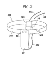
FIG. 2] Fig. 2 is a diagram showing the urine receiver as put on a wearer. - [
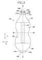
FIG. 3] Fig. 3 is a plan view of the urine receiver. - [
FIG. 4] Fig. 4 is a sectional view taken along line IV-IV inFig. 3 . - [
FIG. 5] Fig. 5 is a sectional view taken along line V-V inFig. 3 . - [
FIG. 6] Fig. 6 is a plan view of a urine sensor. - [
FIG. 7] Fig. 7 is a sectional view taken along line VII-VII inFig. 6 . - [
FIG. 8] Fig. 8 is a plan view of the urine sensor with insulating coating peeled off. - [
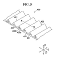
FIG. 9] Fig. 9 is a perspective view of a strip of sheet. - [
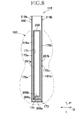
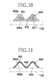
FIG. 10] Fig. 10 is a sectional view taken along line X-X inFig. 9 . - [
FIG. 11] Fig. 11 is a view similar toFig. 10 , exemplarily showing a skin-contact sheet. - [
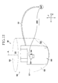
FIG. 12] Fig. 12 is an overall diagram schematically illustrating the system according to the present invention. - [
FIG. 13] Fig. 13 is a plan view of the urine receiver as viewed from its side facing the wearer's body. - [
FIG. 14] Fig. 14 is a sectional view taken along line XIV-XIV inFig. 13 . - [
FIG. 15] Fig. 15 is a sectional view taken along line XV-XV inFig. 13 . - [
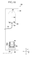
FIG. 16] Fig. 16 is a plan view of the urine receiver as viewed from its side facing the wearer's garment. - [
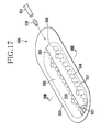
FIG. 17] Fig. 17 is a perspective view of a urine receptacle. - [
FIG. 18] Fig. 18 is a sectional view taken along line XVIII-XVIII inFig. 17 . - [
FIG. 19] Fig. 19 is an overall diagram schematically illustrating the system according to a first embodiment of the present invention. - [
FIG. 20] Fig. 20 is a plan view of the urine receiver as viewed from its side facing the wearer's body. - [
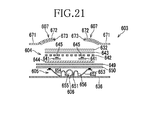
FIG. 21] Fig. 21 is a sectional view taken along line XXI-XXI inFig. 20 . - [
FIG. 22] Fig. 22 is a sectional view taken along line XXI I-XXII inFig. 20 . - [
FIG. 23] Fig. 23 is a plan view of the urine receiver as viewed from its side facing the wearer's garment. - [
FIG. 24] Fig. 24 is a perspective view of the urine receptacle. [FIG. 25 ] -
Fig. 25 is a diagram similar toFig. 19 , schematically illustrating the system according to a second embodiment of the present invention. -
- 100a
- urine suction means
- 102
- urine receiver
- 112
- urine receptacle (container)
- 112a
- opening
- 112b
- bottom
- 112c
- peripheral wall
- 114
- opening
- 143
- electrode
- 143
- electrode
- 134
- liquid-pervious sheet (skin-contact sheet)
- 126
- liquid-pervious sheet (dispersion sheet)
- 400
- strip of sheet
- 400a
- outer surface (upper surface)
- 400b
- inner surface (lower surface)
- 401
- crests
- 402
- troughs
- 407
- thermoplastic synthetic fibers
- P
- longitudinal direction
- Q
- transverse direction
- R
- depth (thickness) direction
- 501
- wearing article
- 502
- chassis
- 503
- receiver
- 504
- moisture sensor structure
- 505
- urine receptacle
- 506
- moisture-absorbent structure
- 521
- front waist region
- 522
- rear waist region
- 523
- crotch region
- 541
- moisture sensors
- 542
- spacer
- 549
- dispersant sheet
- 550
- air permeable-resistant sheet
- 562
- moisture pervious sheet
- 563
- liquid-impervious sheet
- 500P
- suction pump (moisture suction device)
- 601
- wearing article
- 602
- chassis
- 603
- receiver
- 604
- moisture sensor structure
- 605
- urine receptacle (container)
- 606
- mark
- 621
- front waist region
- 622
- rear waist region
- 623
- crotch region
- 626
- window
- 641
- moisture sensor
- 661
- first segment
- 662
- second segment
- 600P
- suction pump
- Details of a urine receiver according to a first aspect of the present invention will be more fully understood from the description given hereunder with reference to the accompanying drawings.
-
Fig. 1 is a schematic diagram illustrating an automaticurine disposal system 100 comprising aurine receiver 102 according to the present invention and vacuum-utilizing urine suction means 100a. Theurine receiver 102 has a side facing the wearer's skin and a side facing the wearer's garment. InFig. 1 , various elements on the side facing the wearer's garment are illustrated as partially cutaway. - The automatic
urine disposal system 100 can automatically collect urine discharged by the wearer into theurine receiver 102 upon urination. Theurine receiver 102 comprises aurine collector unit 102a put in contact with the wearer's skin in the vicinity of the wearer's urethral orifice and adapted to collect discharged urine and aurine sensor unit 102b adapted to detect urination. The vacuum-utilizing urine suction means 100a includes ajoint element 104 by which the suction means 100a is connected to theurine receiver 102, aurine guide tube 106, aurine reservoir 106a, apump unit 108 and anelectric wiring 116. - The
pump unit 108 includes a suction pump (not shown) adapted to be actuated in response to signals transmitted via thewiring 116 from theurine sensor unit 102b. In theurine receiver 102, theurine guide tube 106 is connected via thejoint element 104 to aurine evacuation port 114 formed through aperipheral wall 112c of areceptacle 112 in theurine collector unit 102a. A distal end of thewiring 116 extending from thepump unit 108 is provided with aclip 120 by which a pair ofelectrodes Figs. 3 and4 ) of aurine sensor 118 included by theurine sensor unit 102b are electrically connected to thewiring 116. In such automaticurine disposal system 100, theurine sensor 118 detects occurrence of urination and generates signals on the basis thereof. In response to the signals transmitted from theurine sensor 118, the suction pump included by thepump unit 108 is actuated to suck air within theurine reservoir 106a and thereby to suck urine into theurine receptacle 112 so that the urine sucked in this manner may be further sucked and collected through thejoint element 104 and theurine guide tube 106 into theurine reservoir 106a. -
Fig. 2 exemplarily illustrates how to wear theurine receiver 102. With theurine receiver 102 put on the wearer's body, theclip 120 lies on the wearer's ventral side. A T-belt 300 is used as means to wear theurine receiver 102 on the wearer's body, theurine receiver 102 is fixed to the inner surface of acrotch belt segment 301 as a component of the T-belt 300 with pressure-sensitive adhesives or mechanical fasteners well known by the trade mark "Velcro" (registered trademark). Most part of thereceptacle 112 in theurine receiver 102 extends in the vertical direction along the front side of the wearer's body so that the inner side of theurine receiver 102 may face the urethral orifice, the vicinity thereof and further extends along the inner surface of the crotch-belt segment 301 toward the anus in a gentle curve. Opposite ends of a waist-belt segment 302 as another component of the T-belt 300 are temporarily connected to each other by suitable connector means 303 such as mechanical fasteners. The crotch-belt segment 301 is stitched at one end together with the waist-belt segment 302 and temporarily connected at the other end to the waist-belt segment 302 withmechanical fasteners 304. It should be noted that the means to wear theurine receiver 102 is not limited to the T-belt 302 as illustrated, but the other appropriate means such as open-type diapers, pants-type diapers, diaper chassises or pants for incontinent patient also may be used for the same purpose. -
Fig. 3 is a plan view showing the side of theurine receiver 102 facing the wearer's skin (not shown),Fig. 4 is a sectional view taken along line IV-IV inFig. 3 andFig. 5 is a sectional view taken along line V-V inFig. 3 . InFigs. 4 and5 , most of respective elements of theurine receiver 102 overlapping one another in the thickness direction R are shown to be spaced one from another for convenience of explanation. The thickness direction R may be reworded by the depth direction of thereceptacle 112. As used herein, the term "outward in the depth direction" means the direction from theopening 112a of thereceptacle 112 to the outside of thereceptacle 112 and as used herein, the term "inward in the depth direction" means the direction from theopening 112a to the inside of thereceptacle 112 as viewed inFig. 4 . - The
urine receiver 102 has a longitudinal direction P corresponding to the vertical direction of the wearer's body and a transverse direction Q which is orthogonal to the longitudinal direction P. Theurine receiver 102 has a width which is relative large in the vicinity of its opposite end sections as viewed in the longitudinal direction P and gradually reduced in its middle section. Theurine receiver 102 has a thickness direction R also and includes, above thereceptacle 112 as viewed inFig. 4 , a plurality of sheet-like elements, i.e., a liquid-impervious leakage-barrier sheet 122, an air permeable-resistant and liquid-pervious sheet 124, adispersant sheet 126, acushion sheet 128, theurine sensor 118, a sheet-like spacer 130, a sheet-like filter 132, a liquid-pervious skin-contact sheet 134 and leakage-barrier 136 stacked in this order from below. The leakage-barrier sheet 122, the air permeable-resistant sheet 124 and thedispersant sheet 126 are integrated with thereceptacle 112 to form theurine collector unit 102a. Thecushion sheet 128, theurine sensor 118, thespacer 130, thefilter 132 and the skin-contact sheet 134 are stacked one on another to form theurine sensor unit 102b. - The
receptacle 112 is leak-proof tray-shapedmeans contoured by a bottom 112b, theperipheral wall 112c and anupper opening 112a and made of soft elastic material such as soft polyethylene or silicon rubber. Thereceptacle 112 has flexibility of a degree such that thereceptacle 112 can be inflected in the longitudinal direction P as well as in the transverse direction Q but resist against a deformation due to a negative pressure generated when the suction pump sucks urine. The leakage-barrier sheet 122 is water-tightly bonded to aperipheral flange 152 of thereceptacle 112 with adhesive 112d. - The leakage-
barrier sheet 122 extends outward beyond the peripheral edge thereof to prevent urine from leaking out of theurine receiver 102. The leakage-barrier sheet 122 may be formed of a thermoplastic synthetic resin film or a composite sheet consisting of such film and a nonwoven fabric. In the case of the urine receiver shown inFig. 1 , a soft polyethylene film having a thickness of 30µm may be used for the leakage-barrier sheet 122. In cases where theurine receiver 102 requires no particular leakage-barrier effect along the periphery of thereceptacle 112, the leakage-barrier sheet 22 may be spared from the elements required to exploit the present invention. - The air permeable-
resistant sheet 124 is highly liquid-pervious but absolutely or substantially air-impermeable and covers theupper opening 112a of thereceptacle 112 as seen inFig. 4 . The periphery of thesheet 124 is bonded to the leakage-barrier sheet 122 from above withhot melt adhesives 124a. A negative pressure can be easily generated within thereceptacle 112 covered with the air permeable-resistant sheet 124 sufficiently to suck urine discharged onto the skin-contact sheet 134 rapidly upon actuation of the suction pump of thepump unit 108. The air permeable-resistant sheet 124 may be formed, for example, of an SMS nonwoven fabric consisting of a spun bonded nonwoven fabric having a basis mass of 22g/m2, a melt blown nonwoven fabric having a basis mass of log/m2 and a spun bonded nonwoven fabric having a basis mass of 22g/m2 preferably modified by surfactant so as to become hydrophilic. The air-permeability of the air permeable-resistant sheet 124 determined by Air-Permeability Measuring Method A specified by JIS L 1096, Section 6.27.1 is in a range of 0 to 100cc/cm2/sec, more preferably in a range of 0 to 50cc/cm2/sec in a wet condition and in a range of 20 to 100cc/cm2/sec, more preferably in a range of 20 to 50cc/cm2/sec in a dry condition. The wet condition in which the air-permeability is measured refers to a condition in which the moisture content of the air permeable-resistant sheet 124 calculated according to an equation as indicated below is 100% or higher. The dry condition means the condition of the air permeable-resistant sheet 124 after thissheet 124 has been left for 24 hours or longer in a room at a temperature of 20°C and RH of 50%. -

- The
dispersant sheet 126 is formed of a liquid-pervious sheet such as a nonwoven fabric containing hydrophilic fibers, for example, rayon fibers and serves to disperse urine over the air permeable-resistant sheet 124 as rapidly as possible so that the air permeable-resistant sheet 124 may be wet over an area as wide as possible. Once the air permeable-resistant sheet 124 has been wetted, it is easy to generate a negative pressure within thereceptacle 112 and thereby suck urine into thereceptacle 112. Preferably, thedispersant sheet 126 is intermittently bonded to the air permeable-resistant sheet 124 to prevent liquid-pervious properties of these both sheets from being disturbed. - The
cushion sheet 128 is formed, for example, of a liquid-pervious sheet such as a thermally bonded nonwoven fabric having a basis mass in a range of 20 to 30g/m2 and capable of picking up urine instantaneously at the initial stage of urination to prevent urine staying in thedispersant sheet 126 and the air permeable-resistant sheet 124 from flowing back toward theurine sensor 118. The sheet-like material such as theurine sensor 118, thespacer 130 and thefilter 132 may be previously stacked on thecushion sheet 128 to utilize thecushion sheet 128 as a carrier element serving for previously arranging these sheet-like elements at predetermined positions in theurine receiver 102 in the course of producing theurine receiver 102. Preferably, thecushion sheet 128 is intermittently bonded to thedispersant sheet 126 to prevent the liquid-pervious properties of these both sheets from being disturbed. - The
urine sensor 118 is obtained, for example, by printing a pair of electrodes each having a desired shape on a synthetic resin film with conductive ink and a detailed construction thereof will be described later. Theurine sensor 118 may be located at least in a space defined between the air permeable-resistant sheet 124 and the skin-contact sheet 134 of a plurality of liquid-pervious sheets urine sensor 118 is sandwiched by thecushion sheet 128 and thespacer 130. Theurine sensor 118 may be bonded to thecushion sheet 128. - The
spacer 130 is formed of a liquid-pervious mesh sheet. In theurine receiver 102, a certain quantity of urine should be left in the skin-contact sheet 134 and keep the skin-contact sheet 134 in a wet condition even after suction of urine. If such skin-contact sheet 134 still in a wet condition comes in direct or indirect contact with theurine sensor 118 under a body mass or the other factors, there is a possibility that the urine sensor might malfunction. Thespacer 130 is means serving to keep theurine sensor 118 and thefilter 132 to be spaced from each other in the thickness direction R and thereby to prevent such malfunction of theurine sensor 118. Thespacer 130 is not urine-absorbent but water-repellent and has air-permeability, liquid-permeability and stiffness higher than those of the air permeable-resistant sheet 124 so that thespacer 130 may keep its thickness unchanged even under the body mass.Such spacer 130 may be formed of a mesh sheet having a thickness in a range of 0.5 to 1mm made of a soft synthetic resin such as ethylene-vinyl acetate and bonded to thecushion sheet 128 preferably in such a manner that the liquid-permeably properties of these bothsheets - The
filter 132 serves to avoid a situation in which solid contents of urine might cling to theurine sensor 118 and, in consequence, theurine sensor 118 might be permanently left in a turn-on state. Thefilter 132 may be formed of a sheet material, more preferably of a nonwoven fabric having air-permeability and liquid-permeability higher than those of the air permeable-resistant sheet 124. Thefilter 132 may be intermittently bonded to thespacer 130 to prevent the liquid-permeably properties of these bothsheets - The skin-
contact sheet 134 has anupper surface 134a and alower surface 134b wherein thelower surface 134b is kept in tight contact with the upper surface of thefilter 132. With theurine receiver 102 put on the wearer's body, theupper surface 134a faces the wearer's urination orifice and the vicinity thereof and, in this state, is kept in contact with the wearer's skin. This skin-contact sheet 134 is formed of a sheet material having flexibility and liquid-permeability such as a thermally bonded nonwoven fabric having a basis mass in a range of 15 to 25g/m2. Like thecushion sheet 128, the skin-contact sheet 134 is capable of picking up urine instantaneously at the initial stage of urination and it is preferred to bond the skin-contact sheet 134 intermittently to thefilter 132 so that the liquid-permeable property of these bothsheets contact sheet 134 may be hydrophilic or water-repellent depending on conditions. - Paired right and left leakage-
barriers 136 seen inFigs. 3 and4 are capable of preventing urine from flowing on the skin-contact sheet 134 in the transverse direction Q and leaking sideways out of theurine receiver 102. Of the leakage-barriers 136, outer side edges 136c lying outside theurine receiver 102 are bonded to the skin-contact sheet 134 andinner side edges 136d lying in the vicinity of middle section of theurine receiver 102 are not bonded to the skin-contact sheet 134 wherein theinner side edges 136d are provided withelastic elements 136b such as rubber yarns (SeeFig. 4 ) are attached thereto under tension in the longitudinal direction P. With theurine receiver 102 put on the wearer's body, theelastic elements 136b are curved in the longitudinal direction P as seen inFig. 1 and thereupon and the inner side edges 136d of the leakage-barriers 135 are spaced upward from the skin-contact sheet 134. The leakage-barriers 136 are formed of a soft thermoplastic synthetic resin film or a composite sheet consisting of this film and a nonwoven fabric and are preferably liquid-impervious. As viewed in the plan view of theurine receiver 102, the leakage-barriers 136 (SeeFig. 3 ) have upper and lower ends covered with first andsecond end sheets - With the
urine receiver 102 put on the wearer's body, if defecation occurs and the skin-contact sheet 134 is covered with feces, it will be difficult or sometimes impossible for theurine receiver 102 to detect urination and to start the suction of urine. To solve this problem, theurine receiver 102 is provided with afeces sensor 144 as will be apparent fromFigs. 3 ,4 and5 . In thefeces sensor 144, thermoplastic syntheticresin film sheets electrodes cover sheets cover sheet 142a is liquid-pervious and allows moisture in feces to pass therethrough toward theelectrodes feces sensor 144, theelectrodes urine detecting electrodes lower ends 145b as viewed inFigs. 3 and6 extend downward beyond thesecond end sheet 140. When the lower ends 145b are soiled with feces, moisture in feces permeates thecover sheet 142a, causing theelectrodes power source 116a (SeeFig. 1 ) included by thewiring 116 and an alarm device (not shown) in thepump unit 108 receives signals. In response to the signals, the alarm device prompts the care personnel to deal with feces and to exchange theurine receiver 102 with the fresh one. -
Fig. 6 is a plan view of theurine sensor 118 used in the embodiment illustrated inFigs. 3 ,4 and5 wherein the contour of theurine receiver 102 is indicated by imaginary line. Theurine sensor 118 comprises afilm sheet 260 formed of a synthetic resin film, a pair of theurine detecting electrodes film sheet 260 and the insulatingcoating 170 covering the most part of theseelectrodes film sheet 260 has a rectangular shape which is relatively long in the longitudinal direction P and formed in its middle in the transverse direction Q with a generallyrectangular opening 171 largely cut out in the longitudinal direction P.Such film sheet 260 has anupper end section 266, as viewed inFig. 6 , adapted to be held by theclip 120,lateral sections upper end section 266 on both sides of a central line L1-L1 bisecting a width dimension of theurine sensor 118, alower end section 268a extending downward from the lower end of thelateral section 267a, and alower end section 268b extending from the lower end section of thelateral section 267b. Thelower end section 268a is connected with thelower end section 268b via a connectingregion 268c. In theupper end section 266 of thefilm sheet 260, theelectrodes Fig. 6 , a plurality of small circular regions in thelateral sections lower end sections uncoated regions coating 170 in which aurine detecting region electrode -
Fig. 7 is a sectional view taken along line VII-VII inFig. 6 . Thefilm sheet 260 is formed on its upper surface with, in addition to theurine detecting electrode 218a, aresistive element 250 for detection of burnout and theurine detecting region 175a of theelectrode 218a is exposed in theuncoated region 169a. Theresistive element 250 is entirely covered with the insulatingcoating 170. -
Fig. 8 is a plan view of theurine sensor 118 having the insulating coating peeled off. Thefilm sheet 260 is formed on one surface with the generally L-shapedurine detecting electrode 218a extending along thelateral section 267a and thelower end section 268a and the inverted L-shapedurine detecting electrode 218b extending along thelateral section 267b and thelower end section 268b. Thecircular regions electrodes uncoated regions Fig. 6 . Theresistive element 250 for detection of burnout is formed between theelectrodes resistive element 250 is electrically connected to the respectivelower end sections urine detecting electrodes opening 171. - As the
film sheet 260 preferred to be used insuch urine sensor 118, a polyester film having a thickness in a range of 50 to 100µm may be used. Theelectrodes film sheet 260 with conductive ink or the other conductive coating material in a desired shape. The conductive ink or the conductive coating material may contain carbon black of 3 to 7% by mass, artificial graphite such as carbon graphite of 10 to 30% by mass and an appropriate quantity of silver powder. Each of thepreferred electrodes uncoated regions resistance element 250 may be obtained by printing thefilm sheet 260 with ink, for example, containing carbon black of 3 to 7% by mass and artificial graphite of 5 to 10% by mass in a desired shape. Thisresistance element 250 has a resistance value substantially higher than that of theurine detecting electrodes preferred resistance element 250 has a width dimension of 0.3 to 1mm and a resistance value in the order of 2 to 10MΩ. If the kind of ink used to form theresistance element 250 has conductive properties as high as the type of ink used form theelectrodes resistance element 250 is dimensioned to have a sufficiently large width to make the process easy, a total length of theresistance element 250 may be dimensioned as long as possible so as to extend in the longitudinal direction P along the peripheral edge of theopening 171 and thereby to increase the resistance value thereof. - In the case of the
urine receiver 102 using theurine sensor 118 shown inFig. 6 , thewiring 116 including thepower source 116a normally carries faint current A from thesource 116a via theclip 120 to theelectrodes resistance element 250 electrically connected to theseelectrodes electric circuit 110 including thewiring 116 carries electric current A, theurine detecting electrodes urine detecting electrodes urine sensor 118 is output from thepump unit 108. Referring toFig. 6 , when a range enclosed by animaginary line 176 is wetted with urine, the urine flows into thenon-coated regions urine detecting regions electrode 218a extending along thelateral section 267a and theelectrode 218b extending along thelateral section 267b into the electrically connected state. When a resistance value between theelectrodes resistance element 250, the electric current no more flows through theresistance element 250 but flows through urine of which the resistance value is relatively low. When a value of the electric current B flowing through urine becomes higher than the electric current A flowing through theresistance element 250, theelectric circuit 110 detects such change of the current or an abrupt change of voltage or resistance value and thereby to detect occurrence of urination. In response to signals generated on the basis of such change, the pump is actuated to suck urine and the pump is stopped as the resistance value between theelectrodes - While the
non-coated regions urine detecting regions lateral sections urine sensor 118 shown inFig. 6 , it is also possible to form thesenon-coated regions lower end sections film sheet 260 and in the vicinity of them, a plurality of thenon-coated regions non-coated regions Fig. 6 before reaching the air permeable-resistant sheet 124, theurine receiver 102 is capable of quickly sucking such urine. Alternatively, thenon-coated regions lateral sections urine receiver 102 is put on the wearer's body. -
Fig. 9 is a perspective view of asheet 400 as an example of the skin-contact sheet 134 andFig. 10 is a sectional view taken along line X-X inFig. 9 . Thesheet 400 is formed of a nonwoven fabric containing hydrophobic thermoplastic synthetic fibers of 80 to 100% by mass and liquid-absorbent fibers such as rayon fibers of 20 to 0% by mass wherein these fibers are fusion-bonded or interlaced together. Thesheet 400 has anouter surface 400a facing the wearer's skin and aninner surface 400b facing theurine sensor 108 wherein a longitudinal direction, a transverse direction and a thickness direction correspond to the longitudinal direction P, the transverse direction Q and the thickness direction R of theurine receiver 102, respectively. Theouter surface 400a and theinner surface 400b correspond to the upper surface and the lower surface, respectively, inFig. 4 . - The
outer surface 400a of thesheet 400 has undulation formed ofcrests 401 andtroughs 402 alternating in the longitudinal direction P and thecrests 401 and thetroughs 402 extending in the transverse direction Q in parallel one to another. The inner surface 40b of thesheet 400 is flat and put in close contact with thefilter 132. Thesheet 400 is used in a manner that thecrests 401 and thetroughs 402 may extend across a pair of theelectrodes urine sensor 118 andside edges 403 opposed in the transverse direction Q may be preferably located inside the respective leakage-barriers 136 (SeeFig. 4 ) provided on both sides of theurine receiver 102. - With the
urine receiver 102 using thesheet 400 as the skin-contact sheet 134 and put on the wearer's body, the urine discharged toward thesheet 400 is apt to be collected in thetroughs 402 and then to spread in the transverse direction Q. In theurine receiver 102, therefore, the pairedelectrodes urine receiver 102 can start to suck the discharged urine. Theurine receiver 102 utilizing function of thetroughs 402 of thesheet 400 is advantageous particularly in that, even when the wearer is in the recumbent position, the discharged urine spreads in the transverse direction Q and the pairedelectrodes - The
urine detecting regions Fig. 6 ) in theelectrodes sheet 400 functioning in the manner as described above are preferably formed symmetrically about the center line L1-L1. Thesheet 400 has a basis mass in a range of 15 to 80g/m2 and comprises a plurality of hydrophobic thermoplasticsynthetic fibers 407 each having a fineness in a range of 1 to 8dtex and a fiber length in a range of 20 to 80mm wherein most of the thermoplasticsynthetic fibers 407 are preferably oriented in the transverse direction Q.Such sheet 400 can be obtained by heating and pressing a nonwoven fabric such as a thermally bonded nonwoven fabric between vertically paired molds wherein the upper mold has the crests and the troughs and the lower mold is flat. A machine direction in the course of producing the nonwoven fabric may be aligned with the direction in which the troughs extend to orient the thermoplastic synthetic fibers in the transverse direction Q. Thesheet 400 may be previously treated to become more hydrophilic in thetroughs 402 than in thecrests 401 to promote the movement of the discharged urine from thecrests 401 to thetroughs 402. If desired, it is also possible to make thesheet 400 so that respective tops of thecrests 401 are water-repellent and respective bottoms of thetroughs 402 are hydrophilic. -
Fig. 11 is a view similar toFig. 10 , exemplarily showing thesheet 400 which is different from those shown inFigs. 9 and10 . Thesheet 400 shown inFig. 11 has a generally uniform thickness over its entire area, i.e., theinner surface 400b extends in parallel to theouter surface 400a, and has crests and troughs 411, 412 corresponding to the those 401, 402 of the sheet shown inFigs. 9 and10 . Theinner surface 400b are intermittently bonded or heat-sealed along respective bottoms of the troughs 412 to thefilter 132 facing theinner surface 400b of thesheet 400. In this manner, thesheet 400 is joined to thefilter 132 intermittently in the transverse direction Q and thesheet 400 and thefilter 132 are put in close contact with each other in a region defined between each pair of the adjacent joints so as to facilitate passage of urine through thesheet 400 and thefilter 132.Tunnels 405 extending in the transverse direction Q are defined between thesheet 400 and thefilter 132 and therefore theurine receiver 102 having a feature shown inFig. 11 assures an air-permeability higher than theurine receiver 102 having a feature shown inFigs. 9 and10 . Thesheet 400 exemplarily shown inFig. 11 may be obtained by sandwiching a nonwoven fabric such as a thermally bonded nonwoven fabric between each pair of heated molds from above and below. These paired molds may have the crests and troughs, respectively, adapted to be engaged one with another. - The sheet exemplarily shown in
Figs. 10 and 11 is used not only as the skin-contact sheet 134 but also used so as to lie between the skin-contact sheet 134 andfilter 132 inFig. 4 . When the fiber interstice in thesheet 400 is comparable to the fiber interstice in thefilter 132, thefilter 132 may be replaced by thesheet 400. In any case, thesheet 400 lies outside theelectrodes crests 401 and thetroughs 402 extend across theseelectrodes urine receiver 102 allows theseelectrodes dispersant sheet 126 may be eliminated if the air permeable-resistant sheet 124 contains, in addition to the thermoplastic synthetic fibers, hydrophilic fiber such as rayon fiber and thereby promotes dispersion of urine. - Details of the present invention on the second aspect thereof will be more fully understood from the description exemplarily on the basis of pants formed of a mesh sheet as a wearing article incorporated with the urine receiver.
-
Fig. 12 is an overall diagram schematically illustrating the wearingarticle 501 according to the present invention. According to the present invention, a pants-type chassis 502 is formed therein with aurine receiver 503 to which asuction pump 500P as a suction unit viasuction tube 531. Theurine receiver 503 is electrically connected to thesuction pump 500P which is adapted to be actuated by acontrol unit 500C when amoisture detecting structure 504 incorporated in theurine receiver 503 detects occurrence of urination. Upon actuation of thesuction pump 500P, the urine collected by theurine receiver 503 is sucked and then evacuated out from thechassis 502. InFig. 12 , thechassis 502 is indicated by imaginary lines. - The
chassis 502 comprises afront waist region 521, arear waist region 522 and acrotch region 523 extending between these front andrear waist regions chassis 502 is formed of an elastic mesh sheet so that thechassis 502 may be elasticized in the longitudinal direction Y and in the transverse direction X which is orthogonal to the longitudinal direction Y. Particularly along peripheries of a waist-opening 524 and leg-openings 525, the elasticity is locally heightened to improve a fit of thechassis 502 to the wearer's waist and thighs, respectively.
On the side of thechassis 502 facing the wearer's body, theurine receiver 503 extends in the longitudinal direction Y from thefront waist region 521 to therear waist region 522 along a longitudinal center line A-A bisecting a dimension of thechassis 502 in the transverse direction X. Theurine receiver 503 is kept in close contact with the wearer's body under the effect of elasticity of thechassis 502 so that only theurine receiver 503 may be exchanged as the need arises. -
Fig. 13 is a plan view of theurine receiver 503 as viewed from its side facing the wearer's body. It should be appreciated that theurine receiver 503 is shown as partially cutaway and thechassis 502 is not shown at all for convenience of explanation.Fig. 14 is a sectional view taken along line XIV-XIV inFig. 13 andFig. 15 is a sectional view taken along a line XV-XV inFig. 13 . While the respective sheets are illustrated to be spaced one from another for convenience of explanation inFigs. 14 and15 , these sheets are normally joined together.Fig. 16 is a plan view of the urine receiver ofFig. 13 as viewed from the side facing the wearer's garment. - The
urine receiver 503 comprises atopsheet 532 adapted to come in contact with the wearer's body, amoisture detecting structure 504 serving to detect urination, a tray-shapedurine receptacle 505 located on the side of themoisture detecting structure 504 facing the wearer's body to receive discharged urine and a moistureabsorbent structure 506 lying on the side of theurine receptacle 505 facing the wearer's garment to absorb moisture vapor in thechassis 502.
Thetopsheet 532 may be formed, for example, of a liquid-pervious fibrous nonwoven fabric. Thetopsheet 532 has a generally rectangular shape extending in the longitudinal direction Y and includes opposite side edges 533, 533 extending in the longitudinal direction Y and front andrear ends - The
moisture detecting structure 504 extends thefront waist region 521 to therear waist region 522 of thechassis 502. Themoisture detecting structure 504 comprises a pair ofmoisture detecting sensors 541, aspacer 542 lying on the side of themoisture detecting sensors 541 facing the wearer's body, afilter 543 lying on the side of thespacer 542 facing the wearer's body and acushion sheet 544 lying on the side of themoisture detecting sensors 541 facing the wearer's garment. Specifically, themoisture detecting sensors 541 is sandwiched between thespacer 542 and thecushion sheet 544 in the thickness direction and thereby protected from any external shock. - The
moisture detecting sensors 541 are formed of a pair ofelectrodes electrodes electrodes moisture detecting sensors 541 respectively have front andrear ends front end 546 extends through aslit 561 formed in the moistureabsorbent structure 506 to the side thereof facing the wearer's garment. Theslit 561 is formed on the side of thefront waist region 521. The sensor'sfront end 546 extending out through theslit 561 is provided with aclip 548 via which the signal from themoisture detecting sensors 541 is transmitted to thecontrol unit 500C.
More specifically, themoisture detecting sensors 541 are turned on in response to electrical connection of the pairedelectrodes control unit 500C detects occurrence of urination on the basis of this turned-on state. - As a material for the
spacer 542, a mesh sheet having high air- and liquid-permeability and serves to keep thefilter 543 and themoisture detecting sensors 541 spaced from each other in the thickness direction. If thefilter 543 in a wet condition continues to be kept in contact with themoisture detecting sensors 541, themoisture detecting sensors 541 will be maintained in the turned-on state and may malfunction to detect urination even though no urination occurs. To prevent such malfunction, thefilter 543 and themoisture detecting sensors 541 are kept spaced from each other. For the purpose of preventing such malfunction, use of the spacer is particularly effective since the spacer can effectively prevent thesefilter 543 andmoisture detecting sensors 541 from being continuously kept in contact with each other. - A
dispersant sheet 549 and an air permeable-resistant sheet 550 are stacked on the side of thecushion sheet 544 facing the wearer's garment and theurine receptacle 505 is formed on the side of the air permeable-resistant sheet facing the wearer's garment. The air permeable-resistant sheet 550 and theurine receptacle 505 are joined together, for example, by adhesives.
Thedispersant sheet 549 serves to disperse the discharged urine as quickly as possible and thereby to change the air permeable-resistant sheet 550 over a wide range thereof into a dry condition. As a material for the air permeable-resistant sheet 549, for example, a nonwoven fabric containing hydrophilic fibers such as rayon fibers may be used.
The air permeable-resistant sheet 550 is high in its liquid-permeability but low in its air-permeability and, as a material for thissheet 550, for example, a nonwoven fabric modified to become hydrophilic may be used. - The
urine receptacle 505 is flexible and may be formed, for example, of a liquid-impervious soft elastic material such as a soft polyethylene or silicon rubber.Fig. 17 is a perspective view of theurine receptacle 505 andFig. 18 is a sectional view taken along line XVIII-XVIII inFig. 17 . Theurine receptacle 505 comprises a bottom 551, aperipheral wall 552 rising from the bottom 551 toward the side of the wearer's body, and aflange 553 extending outward from a top peripheral edge of theperipheral wall 552. Theflange 553 is put in contact with the air permeable-resistant sheet 550 to form aspace 554 within theurine receptacle 505. Theurine receptacle 505 is formed with asuction unit 555 functioning to collect the urine flowing thereinto and to evacuate this out of theurine receptacle 505. Thesuction unit 555 has a cylindrical shape and extends along a generally transverse middle zone of thereceptacle 505 in the longitudinal direction. On both sides of thesuction unit 555, a plurality ofprotuberances 556 extend upward from the bottom 551 toward the wearer's body. Theseprotuberances 556 serve to prevent the air permeable-resistant sheet 550 which should be held in contact with theflange 553 from sagging down into thespace 554. - Referring to
Fig. 16 , thesuction unit 555 has oneend 557 opening into theurine receptacle 505 and theother end 558 opening to the outside of theurine receptacle 505. Thesuction tube 531 is attached to theother end 558 of thesuction unit 555 with a joint 559 and thesuction tube 531 is connected to thesuction pump 500P. - The
suction tube 531 and thesuction pump 500P both connected to theother end 558 of thesuction unit 555 define a moisture suction device in the present invention. Upon actuation of thesuction pump 500P, the urine collected in theurine receptacle 505 is sucked through thesuction tube 531. Thesuction pump 500P is electrically connected to thecontrol unit 500C so that thecontrol unit 500C detects occurrence of urination on the basis of signals transmitted from themoisture detecting sensors 541 and thereupon transmits signals to thesuction pump 500P. In response to the signals from thecontrol unit 500C, thesuction pump 500P is actuated. In this way, thesuction pump 500P is actuated only when the urination occurs. - Referring to
Figs. 14 and15 , the moistureabsorbent structure 506 is formed on the side of theurine receptacle 505 facing the wearer's garment. The moistureabsorbent structure 506 comprises a moisture-pervious sheet 562 lying on the side facing the wearer's body, a liquid-impervious sheet 563 lying on the side facing the wearer's garment and moistureabsorbent material 564 lying between these twosheets absorbent material 564 comprises a moisture-absorbent core material such as fluff pulp, superabsorbent polymer particles (SAP) or silica gels wrapped with tissue paper or the like. As a material for the moisture-pervious sheet 562, for example, a thermoplastic drawn film containing inorganic fillers may be used. As the inorganic fillers, calcium carbonate, barium sulfate or the like and, as the thermoplastic film, polyethylene films or the like may be used. As both the inorganic fillers and the thermoplastic films, those widely used in the relevant technical field may be used. Moisture permeability of the moisture-pervious sheet 562 is preferably in a range of 83.3 to 166. 6 (g/m2/24 hours) . If the moisture permeability is lower than 83.3 (g/m2/24 hours) , a significant moisture absorbing effect will not be expressed and, if the moisture permeability is higher than 166.6 (g/m2/24 hours), urine will directly infiltrate into the moisture-absorbent material. In this case, there is a possibility that the urine infiltrating into the moisture-absorbent material may cause a temperature within the wearing article to rise. - Moisture permeability was measured in accordance with JIS-Z-0208. Specifically, circular pieces each having a diameter of 0.03m were cut out from the moisture-pervious sheet as test pieces defining the boundary plane for moisture permeation. A thermo-hygrostat was set to a temperature of 40°C and a humidity of 60%. Total mass (g) of moisture vapor had passed through this boundary plane during 24 hours was converted to the mass per 1m2 of the tested sheet to obtain the moisture permeability.
The moisture permeability was calculated by an equation as follows:
- The moisture-
absorbent structure 506 has a length dimension in the transverse direction X larger than that of themoisture detecting structure 504 lying on the side of the moisture-absorbent structure 506 facing the wearer's body. In other words, the moisture-absorbent structure 506 extends in the transverse direction X beyond the both ends of themoisture detecting structure 504. In the sections extending beyond the both ends of themoisture detecting structure 504, a pair of barrier cuffs 507, 507 against body waste is formed on the side of the moisture-pervious sheet 562 facing the wearer's body constituting the moisture-absorbent structure 506. - The barrier cuffs 507, 507 are attached to side
edges proximal edges pervious sheet 562 andfree edges proximal edges pervious sheet 562. Thesefree edges topsheet 632 facing the wearer's body and provided with cuffelastic elements elastic elements free edges topsheet 532 and thereby prevent urine from leaking outward in the transverse direction X. While the liquid-impervious barrier cuffs 507, 507 are effective to prevent leakage of urine, it is possible to use, for example, moisture-pervious fibrous nonwoven fabric from the viewpoint of permeability for moisture vapor. - Now the manner in which the aforementioned arrangement operates in response to occurrence of urination will be described. Upon occurrence of urination, the urine discharged infiltrates into the
topsheet 532. The barrier cuffs 507, 507 formed along the side edges 533, 533 of the topsheet prevent the urine from leaking outward in the transverse direction X.
The urine having infiltrated into thetopsheet 532 quickly come in contact with themoisture detecting sensors 541 through thespacer 542 and thefilter 543. When urine comes in contact with the pairedmoisture detecting sensors 541 so as to connect these sensors with each other, thesemoisture detecting sensors 541 are turned on and transmit signals to thecontrol unit 500C. In response to this signal, thecontrol unit 500C actuates thesuction pump 500P. Upon actuation of thesuction pump 500P, thespace 554 of theurine receptacle 505 is subjected to a suction effect via asuction unit 555. - The urine having reached the
moisture detecting sensor 541 infiltrates into thedispersant sheet 549 through thecushion sheet 544. The urine havingdispersant sheet 549 over a wide range simultaneously infiltrates into the air permeable-resistant sheet 550 which covers the opening of theurine receptacle 505 to define thespace 554 therein. When thespace 554 is subjected to the suction effect by thesuction pump 500P and the opening is covered with the air permeable-resistant sheet 550 wetted with urine, a negative pressure is generated within thespace 554. As a result, the urine having infiltrated in the air permeable-resistant sheet 550 is sucked into thespace 554 and the urine sucked into thespace 554 is sucked through thesuction tube 555 from theurine receptacle 505. In this way, immediately after occurrence of urination, the discharged urine can be quickly evacuated out of the wearing article. - After the discharged urine has sucked and evacuated, substantially entire quantity of urine is evacuated from the wearing article but there is a possibility that a small quantity of urine might be left, for example, in the
urine receiver 503. Particularly because theurine receptacle 505 is liquid-impervious, the possibility that a small quantity of urine might be left on its side facing the wearer's body is correspondinglyhigh. The urine left not sucked will be vaporized by the wearer's body heat and will pervade the interior of the wearing article. However, the moisture-absorbent structure 506 formed on the side of theurine receiver 503 facing the wearer's garment is effective to absorb such moisture vapor.
Specifically, moisture vapor passes through the moisture-pervious sheet 562 of the moisture-absorbent structure 506 and is absorbed by the moisture-absorbent material 564. The liquid-impervious sheet 563 lies on the side of the moisture-absorbent material 564 and therefore moisture vapor is reliably absorbed by the moisture-absorbent material 564 without leaking out. Even if moisture vapor is generated within the wearingarticle 501, such moisture vapor can be reliably absorbed by the moisture-absorbent material 564. In consequence, there is no possibility that a temperature within the pants might rise and the wearer might suffer from any skin troubles or a discomfortable feeling due to the undesirable humidity. - The moisture
absorbent structure 506 is dimensioned in the transverse direction X to be larger than that of themoisture detecting structure 504. With such dimensioning, moisture vapor can be absorbed by the section extending outward beyond the periphery of theurine receiver 503 and therefore the absorbing function should not be disturbed by various sheets of theurine receiver 503.
Even if moisture vapor within the wearingarticle 501 increases due not only urine but also to the wearer's sweat of the wearer, the moisture-absorbent structure 506 can effectively absorb moisture vapor and thereby restrict increase of temperature. - While the wearer's article is provided with the
moisture detecting sensor 541 serving for detection of urine according to the present embodiment, it is possible to incorporate, in addition to themoisture detecting sensor 541, a feces detecting senor. While the mesh pants are used as thechassis 502 according to the present embodiment, it is also possible to use widely used means such as disposable diapers or diaper covers as thechassis 502. - Details of the present invention on a third aspect thereof will be more fully understood from the description exemplarily on the basis of pants formed of a mesh sheet as a wearing article incorporated with the urine receiver.
-
Figs. 19 through 24 illustrate a first embodiment of the present invention on the third aspect thereof.
Fig. 19 is an overall diagram schematically illustrating the wearingarticle 601 according to the present invention. According to the present invention, a pants-type chassis 602 is formed therein with aurine receiver 603 to which asuction pump 600P as a suction unit viasuction tube 631. Theurine receiver 603 is electrically connected to the suction pump 600Pwhich is adapted to be actuated by acontrol unit 600C when amoisture detecting structure 604 incorporated in theurine receiver 603 detects occurrence of urination. Upon actuation of thesuction pump 600P, the urine collected by theurine receiver 603 is sucked and then evacuated out from thechassis 602. InFig. 19 , thechassis 602 is indicated by imaginary lines. - The
chassis 602 comprises afront waist region 621, arear waist region 622 and acrotch region 623 extending between these front andrear waist regions chassis 602 is formed of an elastic mesh sheet so that thechassis 602 may be elasticized in the longitudinal direction Y and in the transverse direction X which is orthogonal to the longitudinal direction Y. Particularly along peripheries of a waist-opening 624 and leg-openings 625, the elasticity is locally heightened to improve a fit of thechassis 602 to the wearer's waist and thighs, respectively.
In thechassis 602, theurine receiver 603 can be visually recognized through the elastic mesh formed of elastic yarns. - The
receiver 603 extends in the longitudinal direction Y from thefront waist region 621 to therear waist region 622 and along a longitudinal center line A-A bisecting a dimension in the transverse direction X. Thereceiver 603 is kept in close contact with the wearer's body under elastic force of thechassis 602 so that the receiver can be independently exchanged with the fresh one.
Thereceiver 603 includes thetopsheet 632 lying on the side facing the wearer's body and thebacksheet 636 facing the wearer's garment wherein thebacksheet 636 is formed with a linearalignment check mark 606 extending in the longitudinal direction Y. -
Fig. 20 is a plan view showing thereceiver 603 in its developed state and as viewed from the side of the wearer's body. InFig. 20 , thereceiver 603 is shown as partially cutaway and thechassis 602 is not shown for convenience of explanation.Fig. 21 is a sectional view taken along line XXI-XXI inFig. 20 andFig. 22 is a sectional view taken along line XXII-XXII inFig. 20 . InFigs. 21 and22 , the respective sheets are shown as being spaced one from another for convenience of explanation but these sheets are normally joined together.Fig. 23 is a plan view showing thereceiver 603 as viewed from the side of the wearer's garment. - A pair of barrier cuffs 607, 607 against body waste is formed on the side of the
topsheet 632 facing the wearer's body. The barrier cuffs 607, 607 respectively includeproximal edges free edges topsheet 632 and joined to thebacksheet 636. Thefree edges topsheet 632 toward the wearer's body and provided with cuffelastic elements elastic elements free edges topsheet 632 and thereby prevent urine from leaking outward in the transverse direction X. While the liquid-impervious barrier cuffs 607, 607 are effective to prevent leakage of urine, it is possible to use, for example, a moisture-pervious fibrous nonwoven fabric from the viewpoint of permeability for moisture vapor. - Between the top- and
backsheets moisture detecting structure 604 serving to detect occurrence of urination and the tray-shapedurine receptacle 605 lying on the side of themoisture detecting structure 604 facing the wearer's garment and adapted to receive discharged urine.
Themoisture detecting structure 604 extends thefront waist region 621 to therear waist region 622 of thechassis 502. Themoisture detecting structure 604 comprises a pair ofmoisture detecting sensors 641, aspacer 642 lying on the side of themoisture detecting sensors 641 facing the wearer's body, afilter 643 lying on the side of thespacer 642 facing the wearer's body and acushion sheet 644 lying on the side of themoisture detecting sensors 641 facing the wearer's garment. Specifically, themoisture detecting sensors 641 is sandwiched between thespacer 642 and thecushion sheet 644 in the thickness direction and thereby protected from any external shock. - The
moisture detecting sensors 641 are formed of a pair ofelectrodes electrodes electrodes moisture detecting sensors 641 respectively have front andrear ends front end 646 extends through aslit 637 formed in thebacksheet 636 to the side thereof facing the wearer's garment. Theslit 637 is formed on the side of thefront waist region 621. The sensor'sfront end 646 extending out through theslit 637 is provided with aclip 648 via which the signal from themoisture detecting sensors 641 is transmitted to thecontrol unit 600C.
More specifically, themoisture detecting sensors 641 are turned on in response to electrical connection of the pairedelectrodes control unit 600C detects occurrence of urination on the basis of this turned-on state. - As a material for the
spacer 642, a mesh sheet having high air- and liquid-permeability and serves to keep thefilter 643 and themoisture detecting sensors 641 spaced from each other in the thickness direction. If thefilter 643 in a wet condition continues to be kept in contact with themoisture detecting sensors 641, themoisture detecting sensors 641 will be maintained in the turned-on state and may malfunction to detect urination even though no urination occurs. To prevent such malfunction, thefilter 643 and themoisture detecting sensors 641 are kept spaced from each other. For the purpose of preventing such malfunction, use of the spacer is particularly effective since the spacer can effectively prevent thesefilter 643 andmoisture detecting sensors 641 from being continuously kept in contact with each other. - A
dispersant sheet 649 and an air permeable-resistant sheet 650 are stacked on the side of thecushion sheet 644 facing the wearer's garment and theurine receptacle 605 is formed on the side of the air permeable-resistant sheet facing the wearer's garment. The air permeable-resistant sheet 650 and theurine receptacle 605 are joined together, for example, by adhesives.
Thedispersant sheet 649 serves to disperse the discharged urine as quickly as possible and thereby to change the air permeable-resistant sheet 650 over a wide range thereof into a dry condition. As a material for the air permeable-resistant sheet 649, for example, a nonwoven fabric containing hydrophilic fibers such as rayon fibers may be used.
The air permeable-resistant sheet 650 is high in its liquid-permeability but low in its air permeability and, as a material for thissheet 650, for example, a nonwoven fabric modified to become hydrophilic may be used. - The
urine receptacle 605 is flexible and may be formed, for example, by a liquid-impervious soft elastic material such as soft polyethylene or silicon rubber.Fig. 24 is a perspective view of theurine receptacle 605. Theurine receptacle 605 comprises a bottom 651, aperipheral wall 652 rising from the bottom 651 toward the side of the wearer's body, and aflange 653 extending outward from a top peripheral edge of theperipheral wall 652. Theflange 653 is put in contact with the air permeable-resistant sheet 650 to form aspace 654 within theurine receptacle 605. Theurine receptacle 605 is formed with asuction unit 655 functioning to collect the urine flowing thereinto and to evacuate this out of theurine receptacle 605. Thesuction unit 655 has a cylindrical shape and extends along a generally transverse middle zone of thereceptacle 605 in the longitudinal direction. On both sides of thesuction unit 655, a plurality ofprotuberances 656 extend upward from the bottom 651 toward the wearer's body. Theseprotuberances 656 serve to prevent the air permeable-resistant sheet 650 which should be held in contact with theflange 653 from sagging down into thespace 654. - The
suction unit 655 has oneend 657 opening into theurine receptacle 605 and theother end 658 opening to the outside of theurine receptacle 605. Thesuction tube 631 is attached to theother end 658 of thesuction unit 655 with a joint 659 and thesuction tube 631 is connected to thesuction pump 600P. - The
backsheet 636 lies on the side of theurine receiver 605 facing the wearer's garment. Thebacksheet 636 may be formed, for example, of a liquid-impervious fibrous nonwoven fabric. On the side of thebacksheet 636 facing the wearer's garment, thealignment check mark 606 is formed (SeeFigs. 19 and23 ). Thealignment check mark 606 comprises a linearfirst segment 661 extending in the longitudinal direction Y and asecond segment 662 having a dimension in the transverse direction X larger than that of thefirst segment 661. Thefirst segment 661 is formed so as to extend along and on the longitudinal center line A-A and thesecond segment 662 has a generally elliptical shape partially overlapping thefirst segment 661 and defined on the side of thefront waist region 621 about a transverse center line B-B bisecting a dimension of thereceiver 603 in the longitudinal direction Y. Suchalignment check mark 606 may be formed, for example, by printing thebacksheet 636 with appropriate ink or the other coating material. - Now the manner in which the aforementioned arrangement operates in response to occurrence of urination will be described. Upon occurrence of urination, the urine discharged infiltrates into the
topsheet 532. The barrier cuffs 507, 507 formed along the side edges 533, 533 of the topsheet prevent the urine from leaking outward in the transverse direction X.
The urine having infiltrated into thetopsheet 632 quickly come in contact with themoisture detecting sensors 641 through thespacer 642 and thefilter 643. When urine comes in contact with the pairedmoisture detecting sensors 641 so as to connect these sensors with each other, thesemoisture detecting sensors 641 are turned on and transmit signals to thecontrol unit 600C. In response to this signal, thecontrol unit 600C actuates thesuction pump 600P. Upon actuation of thesuction pump 600P, thespace 654 of theurine receptacle 605 is subjected to a suction effect via asuction unit 655. - The urine having reached the
moisture detecting sensor 641 infiltrates into thedispersant sheet 649 through thecushion sheet 644. The urine havingdispersant sheet 649 over a wide range simultaneously infiltrates into the air permeable-resistant sheet 650 which covers the opening of theurine receptacle 605 to define thespace 654 therein. When thespace 654 is subjected to the suction effect by thesuction pump 600P and the opening is covered with the air permeable-resistant sheet 650 wetted with urine, a negative pressure is generated within thespace 654. As a result, the urine having infiltrated in the air permeable-resistant sheet 650 is sucked into thespace 654 and the urine sucked into thespace 654 is sucked through thesuction tube 655 from theurine receptacle 605. In this way, immediately after occurrence of urination, the discharged urine can be quickly evacuated out of the wearing article. - In the aforementioned wearing article, the
receiver 603, eventually, thealignment check mark 606 formed on thereceiver 603 can be visually recognized through thechassis 602. Therefore, it is possible for the care personnel to determine whether thereceiver 603 is displaced or not on the basis of the position of thealignment check mark 606 in the course of putting the wearingarticle 601 on the wearer's body. Occurrence of urination is detected by themoisture detecting sensor 641 when urine comes in contact with a pair of theelectrodes electrodes receiver 603 may be aligned with the intermediate position between the pairedelectrodes - If the
receiver 603 is displaced toward right or left side of the wearer, there is a possibility that the wearer's urine might be discharged outside the pairedelectrodes electrodes electrodes 645 to theother electrode 645. Consequently, it is impossible for a small quantity of urine to bridge the pairedelectrodes electrodes electrodes
According to the present embodiment, theelectrodes alignment check mark 606 is formed along the longitudinal center line A-A. With such arrangement, the highest urine detection accuracy can be assured by putting the article on the wearer's body so that themark 606 may be aligned with the wearer's urethral region. - The
alignment check mark 606 comprises thefirst segment 661 and thesecond segment 662 so that thereceiver 603 may be aligned with the wearer's urethral region particularly by using the second target as a guide. More specifically, the care personnel may place his or her finger on thesecond segment 662 and press the finger against the wearer's urethral region through thereceiver 603 to confirm the wearer's urethral region to align thesecond segment 662 of themark 606 with the wearer's urethral region. Thealignment check mark 606 is positioned between the pairedelectrodes electrodes
Thefirst segment 661 of themark 606 extends in the longitudinal direction Y and makes it possible to determine whether thereceiver 603 is displaced or not over a wide range in the longitudinal direction Y. Considering that the urethral region is generally located along the longitudinal center line of the wearer's body, for example, the first segment may be aligned with the navel in thefront waist region 621 and may be aligned with the bottom cleavage in therear waist region 622 to align the intermediate region between theelectrodes - As has previously been described, it is possible after the article has been put on the wearer's body to determine the relative position between the longitudinal center line A-A of the
receiver 603 and the wearer's body. Therefore, it is possible to correct the displacement of thereceiver 603, if it has been determined. In this way, it is possible to avoid the problem that themoisture detecting sensor 641 of themoisture detecting structure 604 might be out of alignment with the wearer's urethral region and discharged urine could not be detected. - While the wearer's article is provided with the
moisture detecting sensor 641 serving for detection of urine according to the present embodiment, it is possible to incorporate, in addition to themoisture detecting sensor 641, a feces detecting senor. While the mesh pants are used as thechassis 602 according to the present embodiment, it is also possible to use widely used means such as disposable diapers or diaper covers as thechassis 602. - While the
alignment check mark 606 is formed only on thereceiver 603 according to the present embodiment, it is possible to form themark 606 on thechassis 602 also. In this case, thechassis 602 may be formed with themark 606 extending in the longitudinal direction Y along the longitudinal center line of thechassis 602 and thereby the position of thechassis 602 can be adjusted so that the mark on thechassis 602 may be aligned with the mark on thereceiver 603. Generally, thechassis 602 is scarcely displaced and thereceiver 602 may be positioned in alignment with the mark of thechassis 602 to assure that thereceiver 603 is positioned on the center line of the wearer's body. - While the
second segment 662 of themark 606 is positioned on the side of thefront waist region 621 relatively to the transverse center line B-B according to the present embodiment, it is not essential. For example, the position of thesecond segment 662 may be appropriately changed depending on various factors such as the size of the wearing article or thereceiver 603 or gender of the wearer. It should be appreciated that the second segment is not essential to be formed and, in contrast, two or more second segments may be formed, if desired. -
Fig. 25 is a diagram illustrating a second embodiment of the present invention. As will be seen inFig. 25 , thechassis 602 is formed in thecrotch region 623 with awindow 626 in which thereceiver 603 is exposed. Thewindow 626 allows thealignment check mark 606 formed on thereceiver 603 to be visually recognized even if thechassis 602 is made of material having no see-through properties. - It is also possible to form the
chassis 602 as a whole by material having no see-through properties and to form thecrotch region 623 only by materials having see-through properties. For example, thechassis 602 may be formed of an opaque nonwoven fabric made of thermoplastic synthetic resin and a desired region of this nonwoven fabric may be heated under pressure to make it filmy and see-through. Alternatively, thechassis 602 may be formed of an opaque film made of thermoplastic synthetic resin containing inorganic fillers and a desired region of this film may be heated under pressure to smooth such region, to reduce optical diffuse reflection and thereby to make the region see-through. In this case, this film may be laminated together with the nonwoven fabric to reinforce this film or to provide the outer surface with a fabric-like touch. - Whatever the case may be, displacement of the
receiver 603 relative to the wearer's urethral region can be checked and thereby it is assured that occurrence of urination can be detected.
Claims (3)
- A urine receiver comprising a leakage-barrier receptacle having a bottom and a peripheral wall and a top opening, a urine evacuation duct extending through said peripheral wall and adapted to be connected with urine suction means provided separately of said receptacle, a plurality of liquid-pervious sheets stacked one on another to cover said top opening and a pair of electrodes spaced from each other and extending in one direction in parallel to each other wherein, in response to electrical connection of said pair of electrodes via urine contained in one or more of said plurality of liquid-pervious sheets, said urine suction means is actuated to suck the urine discharged by the wearer into said receptacle through said top opening and to evacuate said urine sucked into said receptacle from said receptacle through said urine evacuation duct, said urine receiver being characterized in that:any one of said plurality of liquid-pervious sheets lying outside said pair of electrodes in a depth direction of said receptacle is formed of a nonwoven fabric containing thermoplastic synthetic fibers and has an outer surface facing outward in said depth direction and an inner surface facing inward in said depth direction wherein said outer surface is formed with undulations comprising crests and troughs alternating in said one direction and each of said crests and troughs extends in a direction intersecting with said one direction across said pair of electrodes.
- A wearing article having a longitudinal direction and a transverse direction, comprising a side facing the wearer's body and a side facing the wearer' garment, a chassis having a front waist region, a rear waist region and a crotch region extending between said front and rear waist regions and a receiver adapted to receive bodily fluids discharged onto said chassis wherein the bodily fluids received by said receiver is sucked by a moisture sucking device out of the wearing article, said wearing article being characterized in that:said receiver comprises a receptacle connected to said moisture suction device to collect the bodily fluids received by said receiver and a moisture-absorbent structure lying on the side of said receptacle facing the wearer's garment; andsaid moisture-absorbent structure comprises a moisture-pervious sheet lying on the side of said receptacle facing said wearer's body, a moisture-impervious sheet lying on the said side facing the wearer's garment and a moisture-absorbent material sandwiched between said moisture-pervious sheet and said liquid-impervious sheet.
- A wearing article having a longitudinal direction and a transverse direction, comprising a side facing the wearer's body and a side facing the wearer's garment, a chassis having a front waist region, a rear waist region and a crotch region extending between said front and rear waist regions and a urine receiver adapted to receive bodily fluids discharged onto said chassis wherein the bodily fluids received by said urine receiver is sucked by a moisture sucking device out of the wearing article, said wearing article being characterized in that:said receiver is formed with an alignment check mark adapted to be visually recognized from the outside through said chassis.
Priority Applications (2)
| Application Number | Priority Date | Filing Date | Title |
|---|---|---|---|
| EP11167990.8A EP2374435B1 (en) | 2008-09-19 | 2009-09-17 | Urine receiver and wearing article |
| EP11168588.9A EP2380532B1 (en) | 2008-09-19 | 2009-09-17 | Urine receiver and wearing article |
Applications Claiming Priority (4)
| Application Number | Priority Date | Filing Date | Title |
|---|---|---|---|
| JP2008241779A JP5346193B2 (en) | 2008-09-19 | 2008-09-19 | Wearing article |
| JP2008241778A JP5140528B2 (en) | 2008-09-19 | 2008-09-19 | Wearing article |
| JP2008241776A JP5129073B2 (en) | 2008-09-19 | 2008-09-19 | Urine receiver |
| PCT/JP2009/066265 WO2010032789A1 (en) | 2008-09-19 | 2009-09-17 | Urine receiver and wearing article |
Related Child Applications (4)
| Application Number | Title | Priority Date | Filing Date |
|---|---|---|---|
| EP11168588.9A Division EP2380532B1 (en) | 2008-09-19 | 2009-09-17 | Urine receiver and wearing article |
| EP11167990.8A Division EP2374435B1 (en) | 2008-09-19 | 2009-09-17 | Urine receiver and wearing article |
| EP11167990.8 Division-Into | 2011-05-27 | ||
| EP11168588.9 Division-Into | 2011-06-02 |
Publications (3)
| Publication Number | Publication Date |
|---|---|
| EP2335659A1 true EP2335659A1 (en) | 2011-06-22 |
| EP2335659A4 EP2335659A4 (en) | 2011-10-12 |
| EP2335659B1 EP2335659B1 (en) | 2012-06-06 |
Family
ID=42039611
Family Applications (3)
| Application Number | Title | Priority Date | Filing Date |
|---|---|---|---|
| EP09814633A Not-in-force EP2335659B1 (en) | 2008-09-19 | 2009-09-17 | Urine receiver and wearing article |
| EP11167990.8A Not-in-force EP2374435B1 (en) | 2008-09-19 | 2009-09-17 | Urine receiver and wearing article |
| EP11168588.9A Not-in-force EP2380532B1 (en) | 2008-09-19 | 2009-09-17 | Urine receiver and wearing article |
Family Applications After (2)
| Application Number | Title | Priority Date | Filing Date |
|---|---|---|---|
| EP11167990.8A Not-in-force EP2374435B1 (en) | 2008-09-19 | 2009-09-17 | Urine receiver and wearing article |
| EP11168588.9A Not-in-force EP2380532B1 (en) | 2008-09-19 | 2009-09-17 | Urine receiver and wearing article |
Country Status (7)
| Country | Link |
|---|---|
| US (1) | US20110172625A1 (en) |
| EP (3) | EP2335659B1 (en) |
| CN (2) | CN102196787A (en) |
| AU (1) | AU2009293768A1 (en) |
| MX (1) | MX2011003030A (en) |
| SG (2) | SG189683A1 (en) |
| WO (1) | WO2010032789A1 (en) |
Cited By (2)
| Publication number | Priority date | Publication date | Assignee | Title |
|---|---|---|---|---|
| EP2737882A4 (en) * | 2011-07-29 | 2015-04-29 | Unicharm Corp | Urine absorption device |
| EP3838235A1 (en) * | 2019-12-18 | 2021-06-23 | Curaco, Inc. | Excrement care robot with precision control function of adjacent region to the genitals for making optimal environment insidewearing part of body-fitted type treating apparatus |
Families Citing this family (87)
| Publication number | Priority date | Publication date | Assignee | Title |
|---|---|---|---|---|
| JP5396233B2 (en) * | 2009-10-23 | 2014-01-22 | ユニ・チャーム株式会社 | Defecation and urination discrimination device |
| JP5457904B2 (en) * | 2010-03-26 | 2014-04-02 | ユニ・チャーム株式会社 | Urine processing structure |
| WO2014035340A1 (en) * | 2012-08-28 | 2014-03-06 | Agency For Science, Technology And Research | An apparatus for a diaper, a system, a diaper and a method of manufacturing an electrode |
| US20140333441A1 (en) * | 2013-05-08 | 2014-11-13 | Anthony Solazzo | Diaper Monitor |
| CN103385780A (en) * | 2013-07-31 | 2013-11-13 | 马广丽 | Panties type inflatable leakage-proof woman chamber pot |
| US10226376B2 (en) | 2014-03-19 | 2019-03-12 | Purewick Corporation | Apparatus and methods for receiving discharged urine |
| US10952889B2 (en) | 2016-06-02 | 2021-03-23 | Purewick Corporation | Using wicking material to collect liquid for transport |
| US11090183B2 (en) | 2014-11-25 | 2021-08-17 | Purewick Corporation | Container for collecting liquid for transport |
| US11806266B2 (en) | 2014-03-19 | 2023-11-07 | Purewick Corporation | Apparatus and methods for receiving discharged urine |
| US10390989B2 (en) | 2014-03-19 | 2019-08-27 | Purewick Corporation | Apparatus and methods for receiving discharged urine |
| US9366644B1 (en) | 2014-04-30 | 2016-06-14 | Helvetia Wireless Llc | Systems and methods for detecting a liquid |
| US9506886B1 (en) | 2014-04-30 | 2016-11-29 | Helvetia Wireless Llc | Systems and methods for detecting a liquid |
| US9322797B1 (en) | 2014-04-30 | 2016-04-26 | Helvetia Wireless Llc | Systems and methods for detecting a liquid |
| CN104305927B (en) * | 2014-11-13 | 2017-01-18 | 杨浩 | Urination urgency handling device |
| USD928946S1 (en) | 2016-06-02 | 2021-08-24 | Purewick Corporation | Urine receiving apparatus |
| US10376406B2 (en) | 2016-07-27 | 2019-08-13 | Purewick Corporation | Male urine collection device using wicking material |
| US10973678B2 (en) | 2016-07-27 | 2021-04-13 | Purewick Corporation | Apparatus and methods for receiving discharged urine |
| CN110612075B (en) | 2017-01-31 | 2022-09-09 | 普利维克公司 | Apparatus and method for receiving excreted urine |
| WO2018152156A1 (en) | 2017-02-14 | 2018-08-23 | Sage Products, Llc | Devices and methods for urine collection |
| CN106963558A (en) * | 2017-03-15 | 2017-07-21 | 东莞市南星电子有限公司 | A kind of baby urine wet detection method |
| WO2018221530A1 (en) * | 2017-05-30 | 2018-12-06 | 花王株式会社 | Wearable article equipped with sensor |
| US11721436B2 (en) * | 2017-05-30 | 2023-08-08 | Kao Corporation | Care schedule proposal device |
| USD882768S1 (en) | 2017-09-08 | 2020-04-28 | Sage Products, Llc | Urine collection device |
| JP7072084B2 (en) | 2018-05-01 | 2022-05-19 | ピュアウィック コーポレイション | Fluid collectors, related systems, and related methods |
| CN112804971B (en) | 2018-05-01 | 2024-03-26 | 普利维克公司 | Fluid collection garment |
| CA3098571C (en) * | 2018-05-01 | 2023-09-26 | Purewick Corporation | Fluid collection devices, systems, and methods |
| US11944740B2 (en) | 2018-05-01 | 2024-04-02 | Purewick Corporation | Fluid collection devices, related systems, and related methods |
| US12575961B2 (en) | 2018-05-01 | 2026-03-17 | Purewick Corporation | Fluid collection devices, systems, and methods |
| AU2019262945B2 (en) | 2018-05-01 | 2022-08-25 | Purewick Corporation | Fluid collection devices and methods of using the same |
| AU2019262946B2 (en) * | 2018-05-02 | 2022-06-23 | Purewick Corporation | Fluid collection devices, systems, and methods |
| USD929578S1 (en) | 2019-06-06 | 2021-08-31 | Purewick Corporation | Urine collection assembly |
| CA3143904C (en) * | 2019-06-21 | 2023-11-28 | Purewick Corporation | Fluid collection devices including a base securement area, and related systems and methods |
| CN114375187A (en) | 2019-07-11 | 2022-04-19 | 普奥维克有限公司 | Fluid collection devices, systems, and methods |
| ES2980959T3 (en) | 2019-07-19 | 2024-10-03 | Purewick Corp | Fluid collection devices including at least one shape memory material |
| WO2021046501A1 (en) | 2019-09-06 | 2021-03-11 | Sage Products Llc | Devices and systems for urine collection |
| EP4051190B1 (en) | 2019-10-28 | 2024-05-22 | Purewick Corporation | Fluid collection assemblies including a sample port |
| EP4084746B1 (en) | 2020-01-03 | 2025-04-02 | Purewick Corporation | Urine collection devices having a relatively wide portion and an elongated portion and related methods cross-reference to related applications |
| WO2021155206A1 (en) * | 2020-01-30 | 2021-08-05 | Purewick Corporation | Fluid collection assemblies including a skirt cross-reference to related applications |
| US12589022B2 (en) | 2020-03-19 | 2026-03-31 | Purewick Corporation | Fluid collection assemblies including one or more movement enhancing features |
| WO2021195384A1 (en) | 2020-03-26 | 2021-09-30 | Purewick Corporation | Multi-layered urine capture device and related methods |
| WO2021207621A1 (en) * | 2020-04-10 | 2021-10-14 | Purewick Corporation | Fluid collection assemblies including one or more leak prevention features |
| US12447042B2 (en) | 2020-04-17 | 2025-10-21 | Purewick Corporation | Fluid collection assemblies including a fluid impermeable barrier having a sump and a base |
| US12465514B2 (en) | 2020-04-17 | 2025-11-11 | Purewick Corporation | Fluid collection devices, systems, and methods securing a protruding portion in position for use |
| US12472090B2 (en) | 2020-04-17 | 2025-11-18 | Purewick Corporation | Female external catheter devices having a urethral cup, and related systems and methods |
| WO2021216422A1 (en) | 2020-04-20 | 2021-10-28 | Purewick Corporation | Fluid collection devices adjustable between a vacuum- based orientation and a gravity-based orientation, and related systems and methods |
| US12048643B2 (en) | 2020-05-27 | 2024-07-30 | Purewick Corporation | Fluid collection assemblies including at least one inflation device and methods and systems of using the same |
| USD967409S1 (en) | 2020-07-15 | 2022-10-18 | Purewick Corporation | Urine collection apparatus cover |
| US12685663B2 (en) | 2020-08-05 | 2026-07-21 | Purewick Corporation | Fluid collection devices including an enlarged base, and systems and methods of use |
| WO2022031943A1 (en) | 2020-08-06 | 2022-02-10 | Purewick Corporation | A fluid collection system including a garment and a fluid collection device |
| WO2022035745A1 (en) | 2020-08-11 | 2022-02-17 | Purewick Corporation | Fluid collection devices and methods of manufacturing same cross-reference to related applications |
| US20220047410A1 (en) | 2020-08-11 | 2022-02-17 | Purewick Corporation | Fluid collection assemblies defining waist and leg openings |
| WO2022055957A1 (en) | 2020-09-09 | 2022-03-17 | Purewick Corporation | Fluid collection devices, systems, and methods |
| US12156792B2 (en) | 2020-09-10 | 2024-12-03 | Purewick Corporation | Fluid collection assemblies including at least one inflation device |
| US11801186B2 (en) | 2020-09-10 | 2023-10-31 | Purewick Corporation | Urine storage container handle and lid accessories |
| US12042423B2 (en) | 2020-10-07 | 2024-07-23 | Purewick Corporation | Fluid collection systems including at least one tensioning element |
| US12208031B2 (en) | 2020-10-21 | 2025-01-28 | Purewick Corporation | Adapters for fluid collection devices |
| US12440370B2 (en) | 2020-10-21 | 2025-10-14 | Purewick Corporation | Apparatus with compressible casing for receiving discharged urine |
| US12257174B2 (en) | 2020-10-21 | 2025-03-25 | Purewick Corporation | Fluid collection assemblies including at least one of a protrusion or at least one expandable material |
| US12569365B2 (en) | 2020-10-21 | 2026-03-10 | Purewick Corporation | Fluid collection assemblies including at least one shape memory material disposed in the conduit |
| US12048644B2 (en) | 2020-11-03 | 2024-07-30 | Purewick Corporation | Apparatus for receiving discharged urine |
| US12070432B2 (en) | 2020-11-11 | 2024-08-27 | Purewick Corporation | Urine collection system including a flow meter and related methods |
| US12245967B2 (en) | 2020-11-18 | 2025-03-11 | Purewick Corporation | Fluid collection assemblies including an adjustable spine |
| CN112263377A (en) * | 2020-11-19 | 2021-01-26 | 成惠林 | A real-time urine collection device |
| US12599495B2 (en) | 2021-01-05 | 2026-04-14 | Purewick Corporation | Male external catheter with attachment interface configured to bias against penis |
| US12268627B2 (en) | 2021-01-06 | 2025-04-08 | Purewick Corporation | Fluid collection assemblies including at least one securement body |
| CN116940312A (en) | 2021-01-07 | 2023-10-24 | 普利维克公司 | Wheelchair-mounted urine collection system and related method |
| ES2975761T3 (en) * | 2021-01-19 | 2024-07-15 | Purewick Corp | Variable adjustment liquid collection device |
| US12178735B2 (en) | 2021-02-09 | 2024-12-31 | Purewick Corporation | Noise reduction for a urine suction system |
| JP2023553620A (en) * | 2021-02-26 | 2023-12-25 | ピュアウィック コーポレイション | Fluid collection device having a drainage basin between a pipe opening and a barrier, and related systems and methods |
| US12551385B2 (en) | 2021-03-05 | 2026-02-17 | Purewick Corporation | Fluid collection assembly including a tube having porous wicking material for improved fluid transport |
| US12558472B2 (en) | 2021-03-05 | 2026-02-24 | Purewick Corporation | Portable fluid collection systems with storage and related methods |
| US12458525B2 (en) | 2021-03-10 | 2025-11-04 | Purewick Corporation | Acoustic silencer for a urine suction system |
| US11938054B2 (en) | 2021-03-10 | 2024-03-26 | Purewick Corporation | Bodily waste and fluid collection with sacral pad |
| US12029677B2 (en) | 2021-04-06 | 2024-07-09 | Purewick Corporation | Fluid collection devices having a collection bag, and related systems and methods |
| MX2023011851A (en) | 2021-04-09 | 2023-10-19 | Purewick Corp | Conduits including at least one conduit porous material. |
| TWI755316B (en) * | 2021-04-12 | 2022-02-11 | 醫鼎企業有限公司 | Defecation detection reminder device |
| US11717435B2 (en) * | 2021-04-19 | 2023-08-08 | Lyv Life Inc. | Menstrual disc and methods of use |
| US12233003B2 (en) | 2021-04-29 | 2025-02-25 | Purewick Corporation | Fluid collection assemblies including at least one length adjusting feature |
| US12251333B2 (en) | 2021-05-21 | 2025-03-18 | Purewick Corporation | Fluid collection assemblies including at least one inflation device and methods and systems of using the same |
| US12324767B2 (en) | 2021-05-24 | 2025-06-10 | Purewick Corporation | Fluid collection assembly including a customizable external support and related methods |
| US12150885B2 (en) | 2021-05-26 | 2024-11-26 | Purewick Corporation | Fluid collection system including a cleaning system and methods |
| US12575960B2 (en) | 2021-06-24 | 2026-03-17 | Purewick Corporation | Urine collection systems having one or more of volume, pressure, or flow indicators, and related methods |
| US12551366B2 (en) | 2021-08-02 | 2026-02-17 | Purewick Corporation | Fluid collection devices having multiple fluid collection regions, and related systems and methods |
| JP2024528975A (en) | 2021-08-02 | 2024-08-01 | ピュアウィック コーポレイション | Molded or extruded fluid collection devices and related systems and methods - Patents.com |
| US12594062B2 (en) | 2021-09-08 | 2026-04-07 | Purewick Corporation | Fluid collection assemblies including an extension |
| US20250143910A1 (en) * | 2022-02-03 | 2025-05-08 | Purewick Corporation | External catheter with improved haptic feedback and related systems and methods |
| WO2025179267A1 (en) * | 2024-02-23 | 2025-08-28 | Sage Products, Llc | Devices, systems, and methods for urine diversion |
Family Cites Families (24)
| Publication number | Priority date | Publication date | Assignee | Title |
|---|---|---|---|---|
| JPS61342A (en) * | 1984-06-12 | 1986-01-06 | 大坂 義一 | Evacuation panty |
| KR940003280B1 (en) * | 1991-10-24 | 1994-04-20 | 손종은 | Patient's Stool |
| US5678564A (en) | 1992-08-07 | 1997-10-21 | Bristol Myers Squibb | Liquid removal system |
| US6315765B1 (en) * | 1997-01-17 | 2001-11-13 | Kimberly-Clark Worldwide, Inc. | Elasticized absorbent pad |
| US6160198A (en) * | 1998-06-29 | 2000-12-12 | The Procter & Gamble Company | Disposable article having a discontinuous responsive system |
| EP1110523A1 (en) * | 1999-12-23 | 2001-06-27 | The Procter & Gamble Company | Liquid handling systems comprising three-dimensionally shaped membranes |
| JP3667267B2 (en) * | 2001-09-26 | 2005-07-06 | 大王製紙株式会社 | Absorbent articles |
| US7131964B2 (en) * | 2002-02-26 | 2006-11-07 | Harvie Mark R | Automatic self cleaning bladder relief system and failsafe |
| TWI265024B (en) * | 2003-03-10 | 2006-11-01 | Hitachi Ltd | Automatic urine disposal device and urine receptacle used therefor |
| JP2004267530A (en) * | 2003-03-10 | 2004-09-30 | Hitachi Ltd | Automatic urination processing device and urine receiver used therefor |
| JP2004041697A (en) | 2003-03-31 | 2004-02-12 | Denso Corp | Urine detector |
| TWI248809B (en) * | 2003-08-06 | 2006-02-11 | Hitachi Ltd | Automatic urine disposal device and urine receptacle used therefor |
| JP4283631B2 (en) * | 2003-09-30 | 2009-06-24 | 株式会社日立製作所 | Automatic urination processing apparatus and urine receiver used therefor |
| EP1707170B1 (en) * | 2004-01-23 | 2015-03-11 | Daio Paper Corporation | Absorptive article and inner absorptive article |
| JP2006116348A (en) * | 2004-01-23 | 2006-05-11 | Daio Paper Corp | Absorptive article and inner absorptive article |
| JP3813969B2 (en) | 2004-07-15 | 2006-08-23 | ユニ・チャーム株式会社 | Urine receiver and urine collection processing system using the same |
| US7148396B2 (en) * | 2004-09-15 | 2006-12-12 | Kimberly-Clark Worldwide, Inc. | Disposable garment with system for reducing humidity |
| JP4979999B2 (en) * | 2005-07-13 | 2012-07-18 | ユニ・チャーム株式会社 | Urine sensor |
| CN101217923B (en) * | 2005-07-13 | 2010-10-06 | 尤妮佳股份有限公司 | urine sensor |
| JP4980000B2 (en) * | 2005-07-14 | 2012-07-18 | ユニ・チャーム株式会社 | Urine receiver |
| JP5027455B2 (en) * | 2006-06-29 | 2012-09-19 | ユニ・チャーム株式会社 | Excrement detection sensor |
| JP4747051B2 (en) * | 2006-07-31 | 2011-08-10 | 王子ネピア株式会社 | Pants-type disposable diapers and exterior bodies for pants-type disposable diapers |
| CN201097885Y (en) * | 2007-07-06 | 2008-08-13 | 谢庆云 | Sleeping arrangement |
| JP4384694B2 (en) * | 2008-02-13 | 2009-12-16 | ユニ・チャーム株式会社 | Urine sucking device |
-
2009
- 2009-09-17 CN CN2009801425788A patent/CN102196787A/en active Pending
- 2009-09-17 EP EP09814633A patent/EP2335659B1/en not_active Not-in-force
- 2009-09-17 SG SG2013019930A patent/SG189683A1/en unknown
- 2009-09-17 AU AU2009293768A patent/AU2009293768A1/en not_active Abandoned
- 2009-09-17 US US13/119,771 patent/US20110172625A1/en not_active Abandoned
- 2009-09-17 MX MX2011003030A patent/MX2011003030A/en not_active Application Discontinuation
- 2009-09-17 EP EP11167990.8A patent/EP2374435B1/en not_active Not-in-force
- 2009-09-17 EP EP11168588.9A patent/EP2380532B1/en not_active Not-in-force
- 2009-09-17 CN CN2013102182033A patent/CN103349583A/en active Pending
- 2009-09-17 SG SG2013019633A patent/SG188910A1/en unknown
- 2009-09-17 WO PCT/JP2009/066265 patent/WO2010032789A1/en not_active Ceased
Cited By (2)
| Publication number | Priority date | Publication date | Assignee | Title |
|---|---|---|---|---|
| EP2737882A4 (en) * | 2011-07-29 | 2015-04-29 | Unicharm Corp | Urine absorption device |
| EP3838235A1 (en) * | 2019-12-18 | 2021-06-23 | Curaco, Inc. | Excrement care robot with precision control function of adjacent region to the genitals for making optimal environment insidewearing part of body-fitted type treating apparatus |
Also Published As
| Publication number | Publication date |
|---|---|
| EP2374435B1 (en) | 2014-11-12 |
| EP2380532A1 (en) | 2011-10-26 |
| CN103349583A (en) | 2013-10-16 |
| MX2011003030A (en) | 2011-06-01 |
| WO2010032789A1 (en) | 2010-03-25 |
| AU2009293768A1 (en) | 2010-03-25 |
| EP2335659A4 (en) | 2011-10-12 |
| CN102196787A (en) | 2011-09-21 |
| EP2335659B1 (en) | 2012-06-06 |
| EP2380532B1 (en) | 2014-12-03 |
| EP2374435A1 (en) | 2011-10-12 |
| US20110172625A1 (en) | 2011-07-14 |
| SG188910A1 (en) | 2013-04-30 |
| SG189683A1 (en) | 2013-05-31 |
Similar Documents
| Publication | Publication Date | Title |
|---|---|---|
| US20110172625A1 (en) | Urine receiver and wearing article | |
| EP2243447B1 (en) | Urine suction device | |
| EP2478878B1 (en) | Urine receiver | |
| EP1905400B1 (en) | Urine sensor | |
| EP2243448A1 (en) | An automated urine processing apparatus | |
| US9173799B2 (en) | Urine disposal device | |
| KR101184840B1 (en) | Urine receiver and urine collection processing system implementing urine reciever | |
| US20130006206A1 (en) | Urine absorbent structure | |
| JP2004321460A (en) | Disposable diapers | |
| EP2329801B1 (en) | Excretion sensing device | |
| JP5140528B2 (en) | Wearing article |
Legal Events
| Date | Code | Title | Description |
|---|---|---|---|
| PUAI | Public reference made under article 153(3) epc to a published international application that has entered the european phase |
Free format text: ORIGINAL CODE: 0009012 |
|
| 17P | Request for examination filed |
Effective date: 20110330 |
|
| AK | Designated contracting states |
Kind code of ref document: A1 Designated state(s): AT BE BG CH CY CZ DE DK EE ES FI FR GB GR HR HU IE IS IT LI LT LU LV MC MK MT NL NO PL PT RO SE SI SK SM TR |
|
| AX | Request for extension of the european patent |
Extension state: AL BA RS |
|
| A4 | Supplementary search report drawn up and despatched |
Effective date: 20110908 |
|
| RIC1 | Information provided on ipc code assigned before grant |
Ipc: A61F 5/44 20060101ALI20110902BHEP Ipc: A61F 5/455 20060101AFI20110902BHEP Ipc: A61F 13/42 20060101ALI20110902BHEP Ipc: A61F 13/15 20060101ALI20110902BHEP Ipc: A61F 5/451 20060101ALI20110902BHEP |
|
| DAX | Request for extension of the european patent (deleted) | ||
| GRAP | Despatch of communication of intention to grant a patent |
Free format text: ORIGINAL CODE: EPIDOSNIGR1 |
|
| GRAS | Grant fee paid |
Free format text: ORIGINAL CODE: EPIDOSNIGR3 |
|
| GRAA | (expected) grant |
Free format text: ORIGINAL CODE: 0009210 |
|
| AK | Designated contracting states |
Kind code of ref document: B1 Designated state(s): AT BE BG CH CY CZ DE DK EE ES FI FR GB GR HR HU IE IS IT LI LT LU LV MC MK MT NL NO PL PT RO SE SI SK SM TR |
|
| REG | Reference to a national code |
Ref country code: GB Ref legal event code: FG4D |
|
| REG | Reference to a national code |
Ref country code: AT Ref legal event code: REF Ref document number: 560652 Country of ref document: AT Kind code of ref document: T Effective date: 20120615 Ref country code: CH Ref legal event code: EP |
|
| REG | Reference to a national code |
Ref country code: IE Ref legal event code: FG4D |
|
| REG | Reference to a national code |
Ref country code: DE Ref legal event code: R096 Ref document number: 602009007520 Country of ref document: DE Effective date: 20120809 |
|
| REG | Reference to a national code |
Ref country code: SE Ref legal event code: TRGR |
|
| REG | Reference to a national code |
Ref country code: NL Ref legal event code: VDEP Effective date: 20120606 |
|
| PG25 | Lapsed in a contracting state [announced via postgrant information from national office to epo] |
Ref country code: FI Free format text: LAPSE BECAUSE OF FAILURE TO SUBMIT A TRANSLATION OF THE DESCRIPTION OR TO PAY THE FEE WITHIN THE PRESCRIBED TIME-LIMIT Effective date: 20120606 Ref country code: CY Free format text: LAPSE BECAUSE OF FAILURE TO SUBMIT A TRANSLATION OF THE DESCRIPTION OR TO PAY THE FEE WITHIN THE PRESCRIBED TIME-LIMIT Effective date: 20120606 Ref country code: LT Free format text: LAPSE BECAUSE OF FAILURE TO SUBMIT A TRANSLATION OF THE DESCRIPTION OR TO PAY THE FEE WITHIN THE PRESCRIBED TIME-LIMIT Effective date: 20120606 Ref country code: NO Free format text: LAPSE BECAUSE OF FAILURE TO SUBMIT A TRANSLATION OF THE DESCRIPTION OR TO PAY THE FEE WITHIN THE PRESCRIBED TIME-LIMIT Effective date: 20120906 |
|
| REG | Reference to a national code |
Ref country code: AT Ref legal event code: MK05 Ref document number: 560652 Country of ref document: AT Kind code of ref document: T Effective date: 20120606 |
|
| REG | Reference to a national code |
Ref country code: LT Ref legal event code: MG4D Effective date: 20120606 |
|
| PG25 | Lapsed in a contracting state [announced via postgrant information from national office to epo] |
Ref country code: SI Free format text: LAPSE BECAUSE OF FAILURE TO SUBMIT A TRANSLATION OF THE DESCRIPTION OR TO PAY THE FEE WITHIN THE PRESCRIBED TIME-LIMIT Effective date: 20120606 Ref country code: LV Free format text: LAPSE BECAUSE OF FAILURE TO SUBMIT A TRANSLATION OF THE DESCRIPTION OR TO PAY THE FEE WITHIN THE PRESCRIBED TIME-LIMIT Effective date: 20120606 Ref country code: GR Free format text: LAPSE BECAUSE OF FAILURE TO SUBMIT A TRANSLATION OF THE DESCRIPTION OR TO PAY THE FEE WITHIN THE PRESCRIBED TIME-LIMIT Effective date: 20120907 Ref country code: HR Free format text: LAPSE BECAUSE OF FAILURE TO SUBMIT A TRANSLATION OF THE DESCRIPTION OR TO PAY THE FEE WITHIN THE PRESCRIBED TIME-LIMIT Effective date: 20120606 |
|
| PG25 | Lapsed in a contracting state [announced via postgrant information from national office to epo] |
Ref country code: AT Free format text: LAPSE BECAUSE OF FAILURE TO SUBMIT A TRANSLATION OF THE DESCRIPTION OR TO PAY THE FEE WITHIN THE PRESCRIBED TIME-LIMIT Effective date: 20120606 Ref country code: BE Free format text: LAPSE BECAUSE OF FAILURE TO SUBMIT A TRANSLATION OF THE DESCRIPTION OR TO PAY THE FEE WITHIN THE PRESCRIBED TIME-LIMIT Effective date: 20120606 Ref country code: CZ Free format text: LAPSE BECAUSE OF FAILURE TO SUBMIT A TRANSLATION OF THE DESCRIPTION OR TO PAY THE FEE WITHIN THE PRESCRIBED TIME-LIMIT Effective date: 20120606 Ref country code: NL Free format text: LAPSE BECAUSE OF FAILURE TO SUBMIT A TRANSLATION OF THE DESCRIPTION OR TO PAY THE FEE WITHIN THE PRESCRIBED TIME-LIMIT Effective date: 20120606 Ref country code: IS Free format text: LAPSE BECAUSE OF FAILURE TO SUBMIT A TRANSLATION OF THE DESCRIPTION OR TO PAY THE FEE WITHIN THE PRESCRIBED TIME-LIMIT Effective date: 20121006 Ref country code: SK Free format text: LAPSE BECAUSE OF FAILURE TO SUBMIT A TRANSLATION OF THE DESCRIPTION OR TO PAY THE FEE WITHIN THE PRESCRIBED TIME-LIMIT Effective date: 20120606 Ref country code: EE Free format text: LAPSE BECAUSE OF FAILURE TO SUBMIT A TRANSLATION OF THE DESCRIPTION OR TO PAY THE FEE WITHIN THE PRESCRIBED TIME-LIMIT Effective date: 20120606 Ref country code: RO Free format text: LAPSE BECAUSE OF FAILURE TO SUBMIT A TRANSLATION OF THE DESCRIPTION OR TO PAY THE FEE WITHIN THE PRESCRIBED TIME-LIMIT Effective date: 20120606 |
|
| PG25 | Lapsed in a contracting state [announced via postgrant information from national office to epo] |
Ref country code: PT Free format text: LAPSE BECAUSE OF FAILURE TO SUBMIT A TRANSLATION OF THE DESCRIPTION OR TO PAY THE FEE WITHIN THE PRESCRIBED TIME-LIMIT Effective date: 20121008 Ref country code: PL Free format text: LAPSE BECAUSE OF FAILURE TO SUBMIT A TRANSLATION OF THE DESCRIPTION OR TO PAY THE FEE WITHIN THE PRESCRIBED TIME-LIMIT Effective date: 20120606 Ref country code: IT Free format text: LAPSE BECAUSE OF FAILURE TO SUBMIT A TRANSLATION OF THE DESCRIPTION OR TO PAY THE FEE WITHIN THE PRESCRIBED TIME-LIMIT Effective date: 20120606 |
|
| PLBE | No opposition filed within time limit |
Free format text: ORIGINAL CODE: 0009261 |
|
| STAA | Information on the status of an ep patent application or granted ep patent |
Free format text: STATUS: NO OPPOSITION FILED WITHIN TIME LIMIT |
|
| PG25 | Lapsed in a contracting state [announced via postgrant information from national office to epo] |
Ref country code: DK Free format text: LAPSE BECAUSE OF FAILURE TO SUBMIT A TRANSLATION OF THE DESCRIPTION OR TO PAY THE FEE WITHIN THE PRESCRIBED TIME-LIMIT Effective date: 20120606 Ref country code: MC Free format text: LAPSE BECAUSE OF NON-PAYMENT OF DUE FEES Effective date: 20120930 Ref country code: ES Free format text: LAPSE BECAUSE OF FAILURE TO SUBMIT A TRANSLATION OF THE DESCRIPTION OR TO PAY THE FEE WITHIN THE PRESCRIBED TIME-LIMIT Effective date: 20120917 |
|
| 26N | No opposition filed |
Effective date: 20130307 |
|
| REG | Reference to a national code |
Ref country code: IE Ref legal event code: MM4A |
|
| REG | Reference to a national code |
Ref country code: DE Ref legal event code: R097 Ref document number: 602009007520 Country of ref document: DE Effective date: 20130307 |
|
| PG25 | Lapsed in a contracting state [announced via postgrant information from national office to epo] |
Ref country code: IE Free format text: LAPSE BECAUSE OF NON-PAYMENT OF DUE FEES Effective date: 20120917 Ref country code: BG Free format text: LAPSE BECAUSE OF FAILURE TO SUBMIT A TRANSLATION OF THE DESCRIPTION OR TO PAY THE FEE WITHIN THE PRESCRIBED TIME-LIMIT Effective date: 20120906 |
|
| PG25 | Lapsed in a contracting state [announced via postgrant information from national office to epo] |
Ref country code: MT Free format text: LAPSE BECAUSE OF FAILURE TO SUBMIT A TRANSLATION OF THE DESCRIPTION OR TO PAY THE FEE WITHIN THE PRESCRIBED TIME-LIMIT Effective date: 20120606 |
|
| PG25 | Lapsed in a contracting state [announced via postgrant information from national office to epo] |
Ref country code: TR Free format text: LAPSE BECAUSE OF FAILURE TO SUBMIT A TRANSLATION OF THE DESCRIPTION OR TO PAY THE FEE WITHIN THE PRESCRIBED TIME-LIMIT Effective date: 20120606 |
|
| REG | Reference to a national code |
Ref country code: CH Ref legal event code: PL |
|
| PG25 | Lapsed in a contracting state [announced via postgrant information from national office to epo] |
Ref country code: SM Free format text: LAPSE BECAUSE OF FAILURE TO SUBMIT A TRANSLATION OF THE DESCRIPTION OR TO PAY THE FEE WITHIN THE PRESCRIBED TIME-LIMIT Effective date: 20120606 Ref country code: LU Free format text: LAPSE BECAUSE OF NON-PAYMENT OF DUE FEES Effective date: 20120917 |
|
| PG25 | Lapsed in a contracting state [announced via postgrant information from national office to epo] |
Ref country code: CH Free format text: LAPSE BECAUSE OF NON-PAYMENT OF DUE FEES Effective date: 20130930 Ref country code: HU Free format text: LAPSE BECAUSE OF FAILURE TO SUBMIT A TRANSLATION OF THE DESCRIPTION OR TO PAY THE FEE WITHIN THE PRESCRIBED TIME-LIMIT Effective date: 20090917 Ref country code: LI Free format text: LAPSE BECAUSE OF NON-PAYMENT OF DUE FEES Effective date: 20130930 |
|
| PGFP | Annual fee paid to national office [announced via postgrant information from national office to epo] |
Ref country code: SE Payment date: 20140911 Year of fee payment: 6 |
|
| PG25 | Lapsed in a contracting state [announced via postgrant information from national office to epo] |
Ref country code: MK Free format text: LAPSE BECAUSE OF FAILURE TO SUBMIT A TRANSLATION OF THE DESCRIPTION OR TO PAY THE FEE WITHIN THE PRESCRIBED TIME-LIMIT Effective date: 20120606 |
|
| REG | Reference to a national code |
Ref country code: SE Ref legal event code: EUG |
|
| PG25 | Lapsed in a contracting state [announced via postgrant information from national office to epo] |
Ref country code: SE Free format text: LAPSE BECAUSE OF NON-PAYMENT OF DUE FEES Effective date: 20150918 |
|
| REG | Reference to a national code |
Ref country code: FR Ref legal event code: PLFP Year of fee payment: 8 |
|
| PGFP | Annual fee paid to national office [announced via postgrant information from national office to epo] |
Ref country code: DE Payment date: 20160913 Year of fee payment: 8 Ref country code: GB Payment date: 20160914 Year of fee payment: 8 |
|
| PGFP | Annual fee paid to national office [announced via postgrant information from national office to epo] |
Ref country code: FR Payment date: 20160816 Year of fee payment: 8 |
|
| REG | Reference to a national code |
Ref country code: DE Ref legal event code: R119 Ref document number: 602009007520 Country of ref document: DE |
|
| GBPC | Gb: european patent ceased through non-payment of renewal fee |
Effective date: 20170917 |
|
| REG | Reference to a national code |
Ref country code: FR Ref legal event code: ST Effective date: 20180531 |
|
| PG25 | Lapsed in a contracting state [announced via postgrant information from national office to epo] |
Ref country code: DE Free format text: LAPSE BECAUSE OF NON-PAYMENT OF DUE FEES Effective date: 20180404 Ref country code: GB Free format text: LAPSE BECAUSE OF NON-PAYMENT OF DUE FEES Effective date: 20170917 |
|
| PG25 | Lapsed in a contracting state [announced via postgrant information from national office to epo] |
Ref country code: FR Free format text: LAPSE BECAUSE OF NON-PAYMENT OF DUE FEES Effective date: 20171002 |