EP2335620A2 - Obturator tip - Google Patents
Obturator tip Download PDFInfo
- Publication number
- EP2335620A2 EP2335620A2 EP20100252127 EP10252127A EP2335620A2 EP 2335620 A2 EP2335620 A2 EP 2335620A2 EP 20100252127 EP20100252127 EP 20100252127 EP 10252127 A EP10252127 A EP 10252127A EP 2335620 A2 EP2335620 A2 EP 2335620A2
- Authority
- EP
- European Patent Office
- Prior art keywords
- longitudinal
- arc segment
- longitudinal arc
- curvature
- surgical instrument
- Prior art date
- Legal status (The legal status is an assumption and is not a legal conclusion. Google has not performed a legal analysis and makes no representation as to the accuracy of the status listed.)
- Granted
Links
- 230000000916 dilatatory effect Effects 0.000 claims abstract description 52
- 230000000149 penetrating effect Effects 0.000 claims abstract description 16
- 238000003780 insertion Methods 0.000 claims abstract description 8
- 230000037431 insertion Effects 0.000 claims abstract description 8
- 230000002093 peripheral effect Effects 0.000 claims description 18
- 230000003247 decreasing effect Effects 0.000 claims description 3
- 230000008901 benefit Effects 0.000 description 2
- 239000000560 biocompatible material Substances 0.000 description 2
- 208000014674 injury Diseases 0.000 description 2
- 239000000463 material Substances 0.000 description 2
- 238000012986 modification Methods 0.000 description 2
- 230000004048 modification Effects 0.000 description 2
- 238000001356 surgical procedure Methods 0.000 description 2
- 230000008733 trauma Effects 0.000 description 2
- 241001631457 Cannula Species 0.000 description 1
- 239000004793 Polystyrene Substances 0.000 description 1
- 239000000853 adhesive Substances 0.000 description 1
- 230000001070 adhesive effect Effects 0.000 description 1
- 238000013459 approach Methods 0.000 description 1
- 230000015572 biosynthetic process Effects 0.000 description 1
- 230000008878 coupling Effects 0.000 description 1
- 238000010168 coupling process Methods 0.000 description 1
- 238000005859 coupling reaction Methods 0.000 description 1
- 230000006378 damage Effects 0.000 description 1
- 238000013461 design Methods 0.000 description 1
- 230000010339 dilation Effects 0.000 description 1
- 238000012976 endoscopic surgical procedure Methods 0.000 description 1
- 238000012830 laparoscopic surgical procedure Methods 0.000 description 1
- 238000004519 manufacturing process Methods 0.000 description 1
- 238000000034 method Methods 0.000 description 1
- 230000003287 optical effect Effects 0.000 description 1
- 239000004417 polycarbonate Substances 0.000 description 1
- 229920000515 polycarbonate Polymers 0.000 description 1
- 229920000642 polymer Polymers 0.000 description 1
- 229920002223 polystyrene Polymers 0.000 description 1
- 210000004258 portal system Anatomy 0.000 description 1
- 239000007787 solid Substances 0.000 description 1
- 229910001220 stainless steel Inorganic materials 0.000 description 1
- 239000010935 stainless steel Substances 0.000 description 1
- 230000000451 tissue damage Effects 0.000 description 1
- 231100000827 tissue damage Toxicity 0.000 description 1
- 239000012780 transparent material Substances 0.000 description 1
- 238000003466 welding Methods 0.000 description 1
Images

Classifications
-
- A—HUMAN NECESSITIES
- A61—MEDICAL OR VETERINARY SCIENCE; HYGIENE
- A61B—DIAGNOSIS; SURGERY; IDENTIFICATION
- A61B17/00—Surgical instruments, devices or methods
- A61B17/34—Trocars; Puncturing needles
- A61B17/3494—Trocars; Puncturing needles with safety means for protection against accidental cutting or pricking, e.g. limiting insertion depth, pressure sensors
- A61B17/3496—Protecting sleeves or inner probes; Retractable tips
-
- A—HUMAN NECESSITIES
- A61—MEDICAL OR VETERINARY SCIENCE; HYGIENE
- A61B—DIAGNOSIS; SURGERY; IDENTIFICATION
- A61B17/00—Surgical instruments, devices or methods
- A61B17/34—Trocars; Puncturing needles
- A61B17/3417—Details of tips or shafts, e.g. grooves, expandable, bendable; Multiple coaxial sliding cannulas, e.g. for dilating
- A61B17/3421—Cannulas
-
- A—HUMAN NECESSITIES
- A61—MEDICAL OR VETERINARY SCIENCE; HYGIENE
- A61B—DIAGNOSIS; SURGERY; IDENTIFICATION
- A61B17/00—Surgical instruments, devices or methods
- A61B17/34—Trocars; Puncturing needles
- A61B17/3417—Details of tips or shafts, e.g. grooves, expandable, bendable; Multiple coaxial sliding cannulas, e.g. for dilating
- A61B17/3421—Cannulas
- A61B17/3423—Access ports, e.g. toroid shape introducers for instruments or hands
-
- A—HUMAN NECESSITIES
- A61—MEDICAL OR VETERINARY SCIENCE; HYGIENE
- A61M—DEVICES FOR INTRODUCING MEDIA INTO, OR ONTO, THE BODY; DEVICES FOR TRANSDUCING BODY MEDIA OR FOR TAKING MEDIA FROM THE BODY; DEVICES FOR PRODUCING OR ENDING SLEEP OR STUPOR
- A61M29/00—Dilators with or without means for introducing media, e.g. remedies
-
- A—HUMAN NECESSITIES
- A61—MEDICAL OR VETERINARY SCIENCE; HYGIENE
- A61B—DIAGNOSIS; SURGERY; IDENTIFICATION
- A61B17/00—Surgical instruments, devices or methods
- A61B17/34—Trocars; Puncturing needles
- A61B17/3417—Details of tips or shafts, e.g. grooves, expandable, bendable; Multiple coaxial sliding cannulas, e.g. for dilating
- A61B2017/3454—Details of tips
Definitions
- the present disclosure is directed towards an instrument for use in surgical procedures. More particularly, the present disclosure relates to an obturator or dilating member for use with a surgical portal or access assembly.
- endoscopic and laparoscopic surgical procedures are performed through surgical access devices that include narrow tubular sleeves or cannulas in an insufflated workspace inserted percutaneously into a patient through a small incision, puncture, or access point.
- the incision or access point created in the tissue is very small so as to minimize both tissue trauma and the invasive nature of the procedure.
- a surgical instrument such as an obturator, stylet, or trocar.
- substantial force may be required to insert the instrument through the access point and thereby dilate the opening, potentially resulting in damage or trauma to the tissue surrounding the access point as well as to the internal surgical site. Accordingly, there exists a need in the art for a surgical instrument that includes an improved tip which facilitates the dilation of a percutaneous access point and curtails the risk of tissue damage.
- a surgical instrument for use with a surgical portal apparatus includes an elongate shaft having proximal and distal ends and defining a longitudinal axis and a dilating member disposed at the distal end of the elongate shaft.
- the dilating member has a first longitudinal arc segment and a second longitudinal arc segment in diametrical opposed relation to the first longitudinal arc segment.
- the first and second longitudinal arc segments define respective first and second radii of curvature transverse to the longitudinal axis.
- the first and second radii of curvature decrease from proximal to distal to define a generally tapered configuration of the dilating member.
- the first radius of curvature is greater than the second radius of curvature at predefined longitudinal positions of the dilating member such that the first longitudinal arc segment extends distally beyond the second longitudinal segment to define a penetrating tip.
- the penetrating tip has a reduced profile and dimensioned to facilitate initial insertion of the dilating member into tissue.
- the first and second radii of curvature may be each dimensioned to decrease in a non-linear manner from distal to proximal or may gradually decrease to define a conic section.
- the first and second longitudinal arc segments each define a generally semi-hemispherical shape in cross-section.
- the penetrating tip may include a substantially planar surface.
- the elongate shaft may define a radius of curvature greater than a maximum value of the second radius of curvature of the second longitudinal arc segment.
- the juncture of the second longitudinal arc segment and the elongate shaft defines a vertical surface in general transverse relation to the longitudinal axis, The vertical surface extends about the second longitudinal arc segment.
- the vertical surface may be substantially planar.
- the first longitudinal arc segment and the second longitudinal arc segment may intersect along a median plane of intersection.
- the first longitudinal arc segment may define a peripheral surface circumscribing an outer periphery of the second longitudinal arc segment.
- the peripheral surface may be coplanar with the median plane of intersection.
- the peripheral surface may be substantially planar.
- FIG. 1 is a perspective view of a surgical portal system in conjunction with an obturator instrument in accordance with the principles of the present disclosure
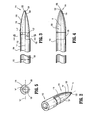
- FIG. 2 is a perspective view of the dilating member of the obturator instrument of FIG. 1 ;
- FIG. 3 is a side plan view of the dilating member of the obturator instrument
- FIG. 4 is a top plan view of the dilating member.
- FIG. 5 is an axial view of the dilating member.
- proximal as is traditional will refer to the end of the apparatus or instrument of the present disclosure which is closest to the clinician, while the term “distal” will refer to the end of the device or instrument which is furthest from the clinician.
- FIG. 1 illustrates a surgical portal or access apparatus 10 and a dilating surgical instrument, member, or obturator 100 in accordance with the present disclosure.
- access apparatus 10 includes a housing 12 configured for the internal receipt of a seal or valve, as is known in the art. Extending distally from housing 12 is a shaft or cannula 16 having respective proximal and distal ends 18, 20 and defining a lumen 22 therethrough. Housing 12, distal end 20 of cannula 16, and the lumen 22 defined therethrough are each dimensioned such that the obturator instrument 100 may pass therethrough.
- obturator instrument 100 has a proximal end 102, a distal end 104, and a shaft 106 disposed therebetween.
- obturator instrument 100 is coupled to a gripping member 108 that is configured and dimensioned to facilitate gripping by a clinician, operator, or surgeon.
- the gripping member may include a cushioning member or portion that is configured to at least partially absorb the force applied to the gripping member by the clinician, as well as the impact of that force upon the clinician's hand, during the distal advancement of the obturator instrument through a patient's tissue.
- the cushioning member may be formed of any material that is at least semi-resilient in nature including, but not limited to, polymers.
- the coupling between proximal end 102 and gripping member 108 may be either fixed or movable, e.g. pivotable, and may be either permanent or releasable.
- Shaft 106 of obturator instrument 100 is an elongate member defining a diameter "D 1 ".
- Diameter "D 1 " is of a suitable dimension such that shaft 106 does not significantly deform or buckle under the influence of the force applied to the gripping member by the clinician, as discussed above.
- “D 1 " may be any diameter substantially within the range of approximately 3mm to approximately 15mm.
- the length of shaft 106 may be of any dimension suitable for the intended purpose of accessing a patient's tissue through the cannula of a surgical access apparatus.
- Disposed at distal end 104 of obturator instrument 100 is a dilating member or member 110.
- Dilating member 110 has a proximal or trailing end 112, a distal or leading end or tip 114, and an outer surface 116 that extends therebetween.
- Dilating member 110 may be formed of any suitable biocompatible material, including but not limited to polycarbonate, polystyrene, or other suitable polymeric material, and also may be fabricated from stainless steel or the like.
- Dilating member 110 may be transparent or opaque, and may be either a solid member or at least partially hollow as shown.
- Proximal end 112 of dilating member 110 is associated with shaft 106.
- shaft 106 and proximal end 112 of dilating member 110 are monolithically formed such that dilating member 110 and shaft 106 are a single unit.
- dilating member 110 and shaft 106 may be separate components joined to each other during manufacture by any suitable manner including, but not limited to, the use of adhesives, monolithic formation, or welding.
- shaft 106 and proximal end 112 of dilating member 110 may be releasably connected through the use of any suitable structural mechanism, including but not limited to, a screw-type or interference-fit arrangement and possibly, joined at the operative site.
- Outer surface 116 of dilating member 110 includes a first longitudinal arc segment 118 and a second longitudinal arc segment 120 in diametrical opposed relation to the first longitudinal arc segment 118.
- Each longitudinal arc segment 118, 120 defines a respective radius of curvature “r1", “r2” generally transverse to the longitudinal axis "k”.
- the radii of curvature "r1", “r2" of the first and second longitudinal arc segments 118, 120 generally decrease from proximal end to distal end to define a generally tapered configuration.
- the first radius of curvature "r1" of the first longitudinal arc segment 118 is greater than the second radius of curvature "r2" of the second longitudinal arc segment 120 at predefined or common longitudinal positions of the dilating member 110. Accordingly, the first longitudinal arc segment 118 may extend distally beyond the second longitudinal arc segment 120 to define a penetrating or leading tip 114. In one embodiment, the respective radii of curvature "r1", "r2" decrease in a linear manner to define a generally linear taper. In another embodiment depicted in FIGS.
- first and second longitudinal segments 118,120 may define a substantially semi-hemispheric cross-section.
- the cross-sectional dimensions of each of first and second longitudinal segments 118, 120 may be in the shape of a segment of an ellipse.
- First and second longitudinal segments 118, 120 may intersect along a median plane of intersection "m" which is coincident with the central longitudinal axis "k", although, in other embodiments, first and second longitudinal segments 118, 120 may intersect along a median plane of intersection "m” which is not coincident with the central longitudinal axis "k.”
- the maximum value of the first radius of curvature "r1" of the first longitudinal arc segment 118 generally approaches or approximates the radius of curvature of the elongate shaft 106 while the maximum value of the second radius of curvature "r2" of the second longitudinal arc segment 120 is less than that of the elongate shaft 106.
- Penetrating tip 114 of dilating member includes leading atraumatic surface 122 of first longitudinal arc segment 118, leading atraumatic surface 124 of second longitudinal arc segment 120 and a substantially planar surface 128 interconnecting the leading atraumatic surfaces 122, 124.
- Planar surface 128 may or may not extend parallel to the longitudinal axis "k". In one embodiment, planar surface 128 is coincident with the median plane of intersection "m" of first and second longitudinal arc segments 118, 120.
- the described arrangement presents a substantially reduced profile to penetrating tip 114, which, substantially facilitates initial insertion of the dilating member 110 into tissue.
- leading atraumatic surface 122 of first longitudinal arc segment 118 may be inserted initially within a path or passage through tissue, or, possibly used to create a path through tissue by virtue of its small axial profile.
- Leading atraumatic surface 122 may be positioned and advanced within the tissue with relative ease through the presence of the planar surface 126 and the gap extending to the leading atraumatic surface 124 of second longitudinal arc segment 120.
- the tissue is dissected along one side of the dilating member 110, i.e., along the first longitudinal arc segment 118.
- second leading surface 124 contacts the tissue to gradually dilate the tissue along the second longitudinal segment 120.
- peripheral surface 128 of first longitudinal arc segment 118 which circumscribes the outer periphery of the second longitudinal segment 120.
- Peripheral surface 128 may be substantially planar and may be disposed along the median plan of intersection "m" of the first and second longitudinal arc segments 118,120.
- Peripheral surface 128 provides advantages with respect to approaching the tissue with the dissecting element 110 from an offset or angulated orientation (i.e., without penetrating tip 114 directly engaging the tissue). In this manner, peripheral surface 128 will initially contact the surface. The reduced profile as provided by the planar aspect of peripheral surface 128 facilitates entry within the tissue.
- a transverse or vertical surface 130 is defined at the juncture of second longitudinal segment 120 and elongate shaft 106 and extends about the second longitudinal arc segment.
- vertical surface 130 is dimensioned to provide the clinician with a tactile indicator indicating when the dilating member 110 has passed through the tissue entry location.
- Planar surface 126 of penetrating tip 114 and peripheral edge 128 may be substantially blunt or define substantially blunt edges. Planar surface 126 and/or peripheral edge 128 may assist in initially lifting tissue defining a tract away from adjacent tissue portions to facilitate continued insertion of dilating member 110. For example, planar surface 126 and/or peripheral edge 128 may decrease the surface area of the dilating member 110 that is in contact with the patient's tissue (not shown). By decreasing this surface area, any adhesion between the tissue (not shown) and the dilating member 110 that may otherwise occur during the insertion and distal advancement of obturator instrument 100 is substantially minimized.
- planar surface 126 and peripheral edge 128 of dilating member 110 are depicted as substantially blunt, the inclusion of one or more substantially incisive or sharp edge members, either in addition to or in place of the blunt edge members disclose above, are within the scope of the present disclosure.
- Dilating member 110 may include one or more transparent portions such that light is permitted to pass through the dilating member 110.
- the transparent portions may be formed of any suitable biocompatible material that is at least translucent.
- Dilating member 110 may include an internal lumen 132 therethrough that is configured and dimensioned to receive an endoscope or other suitable viewing instrument such that a clinician may view a patient's tissue (not shown) via the endoscope and the transparent portions of obturator dilating member 110 during the course of the surgical procedure. Further information regarding the use of optical or transparent materials in surgical access devices may be obtained through reference to commonly assigned U.S. Patent No. 6,685,630 to Sauer, et al. , the entire contents of which are hereby incorporated by reference.
Landscapes
- Health & Medical Sciences (AREA)
- Life Sciences & Earth Sciences (AREA)
- Surgery (AREA)
- General Health & Medical Sciences (AREA)
- Veterinary Medicine (AREA)
- Engineering & Computer Science (AREA)
- Biomedical Technology (AREA)
- Animal Behavior & Ethology (AREA)
- Heart & Thoracic Surgery (AREA)
- Public Health (AREA)
- Pathology (AREA)
- Nuclear Medicine, Radiotherapy & Molecular Imaging (AREA)
- Medical Informatics (AREA)
- Molecular Biology (AREA)
- Anesthesiology (AREA)
- Hematology (AREA)
- Surgical Instruments (AREA)
Abstract
Description
- The present application claims the benefit of and priority to
U.S. Provisional Application Serial No. 61/287,411 filed on December 17, 2009 - The present disclosure is directed towards an instrument for use in surgical procedures. More particularly, the present disclosure relates to an obturator or dilating member for use with a surgical portal or access assembly.
- Generally, endoscopic and laparoscopic surgical procedures are performed through surgical access devices that include narrow tubular sleeves or cannulas in an insufflated workspace inserted percutaneously into a patient through a small incision, puncture, or access point.
- Initially, the incision or access point created in the tissue is very small so as to minimize both tissue trauma and the invasive nature of the procedure. However, to facilitate the insertion of the access device into the patient's tissue, it is often necessary to enlarge or dilate the access point using a surgical instrument such as an obturator, stylet, or trocar. Given the design of known surgical instrument tips, substantial force may be required to insert the instrument through the access point and thereby dilate the opening, potentially resulting in damage or trauma to the tissue surrounding the access point as well as to the internal surgical site. Accordingly, there exists a need in the art for a surgical instrument that includes an improved tip which facilitates the dilation of a percutaneous access point and curtails the risk of tissue damage.
- Accordingly, a surgical instrument for use with a surgical portal apparatus includes an elongate shaft having proximal and distal ends and defining a longitudinal axis and a dilating member disposed at the distal end of the elongate shaft. The dilating member has a first longitudinal arc segment and a second longitudinal arc segment in diametrical opposed relation to the first longitudinal arc segment. The first and second longitudinal arc segments define respective first and second radii of curvature transverse to the longitudinal axis. The first and second radii of curvature decrease from proximal to distal to define a generally tapered configuration of the dilating member. The first radius of curvature is greater than the second radius of curvature at predefined longitudinal positions of the dilating member such that the first longitudinal arc segment extends distally beyond the second longitudinal segment to define a penetrating tip. The penetrating tip has a reduced profile and dimensioned to facilitate initial insertion of the dilating member into tissue.
- The first and second radii of curvature may be each dimensioned to decrease in a non-linear manner from distal to proximal or may gradually decrease to define a conic section. The first and second longitudinal arc segments each define a generally semi-hemispherical shape in cross-section.
- The penetrating tip may include a substantially planar surface. The elongate shaft may define a radius of curvature greater than a maximum value of the second radius of curvature of the second longitudinal arc segment. The juncture of the second longitudinal arc segment and the elongate shaft defines a vertical surface in general transverse relation to the longitudinal axis, The vertical surface extends about the second longitudinal arc segment. The vertical surface may be substantially planar.
- The first longitudinal arc segment and the second longitudinal arc segment may intersect along a median plane of intersection. The first longitudinal arc segment may define a peripheral surface circumscribing an outer periphery of the second longitudinal arc segment. The peripheral surface may be coplanar with the median plane of intersection. The peripheral surface may be substantially planar.
- The accompanying drawings, which are incorporated in, and constitute a part of this specification, illustrate embodiments of the disclosure and, together with a general description of the disclosure given above and the detailed description of the embodiment(s) given below, serve to explain the principles of the disclosure, wherein:
-
FIG. 1 is a perspective view of a surgical portal system in conjunction with an obturator instrument in accordance with the principles of the present disclosure; -
FIG. 2 is a perspective view of the dilating member of the obturator instrument ofFIG. 1 ; -
FIG. 3 is a side plan view of the dilating member of the obturator instrument; -
FIG. 4 is a top plan view of the dilating member; and -
FIG. 5 is an axial view of the dilating member. - Specific embodiments of the presently disclosed apparatus will now be described in detail with reference to the foregoing figures, wherein like reference numerals identify similar or identical elements. In the figures and in the description which follows, the term "proximal", as is traditional will refer to the end of the apparatus or instrument of the present disclosure which is closest to the clinician, while the term "distal" will refer to the end of the device or instrument which is furthest from the clinician.
- Referring now to the drawings,
FIG. 1 illustrates a surgical portal oraccess apparatus 10 and a dilating surgical instrument, member, orobturator 100 in accordance with the present disclosure. - At a proximal end,
access apparatus 10 includes ahousing 12 configured for the internal receipt of a seal or valve, as is known in the art. Extending distally fromhousing 12 is a shaft orcannula 16 having respective proximal anddistal ends lumen 22 therethrough.Housing 12,distal end 20 ofcannula 16, and thelumen 22 defined therethrough are each dimensioned such that theobturator instrument 100 may pass therethrough. - Referring now to
FIGS. 1-3 ,obturator instrument 100 has aproximal end 102, adistal end 104, and ashaft 106 disposed therebetween. Atproximal end 102,obturator instrument 100 is coupled to a grippingmember 108 that is configured and dimensioned to facilitate gripping by a clinician, operator, or surgeon. In one embodiment, the gripping member may include a cushioning member or portion that is configured to at least partially absorb the force applied to the gripping member by the clinician, as well as the impact of that force upon the clinician's hand, during the distal advancement of the obturator instrument through a patient's tissue. The cushioning member may be formed of any material that is at least semi-resilient in nature including, but not limited to, polymers. The coupling betweenproximal end 102 and grippingmember 108 may be either fixed or movable, e.g. pivotable, and may be either permanent or releasable. -
Shaft 106 ofobturator instrument 100 is an elongate member defining a diameter "D1". Diameter "D1" is of a suitable dimension such thatshaft 106 does not significantly deform or buckle under the influence of the force applied to the gripping member by the clinician, as discussed above. "D1" may be any diameter substantially within the range of approximately 3mm to approximately 15mm. The length ofshaft 106 may be of any dimension suitable for the intended purpose of accessing a patient's tissue through the cannula of a surgical access apparatus. Disposed atdistal end 104 ofobturator instrument 100 is a dilating member ormember 110. - Referring now to
FIGS. 2-5 , in conjunction withFIG. 1 , dilatingmember 110 will be described in detail. Dilatingmember 110 has a proximal ortrailing end 112, a distal or leading end ortip 114, and anouter surface 116 that extends therebetween. Dilatingmember 110 may be formed of any suitable biocompatible material, including but not limited to polycarbonate, polystyrene, or other suitable polymeric material, and also may be fabricated from stainless steel or the like. Dilatingmember 110 may be transparent or opaque, and may be either a solid member or at least partially hollow as shown. -
Proximal end 112 of dilatingmember 110 is associated withshaft 106. In one embodiment,shaft 106 andproximal end 112 of dilatingmember 110 are monolithically formed such that dilatingmember 110 andshaft 106 are a single unit. In the alternative, dilatingmember 110 andshaft 106 may be separate components joined to each other during manufacture by any suitable manner including, but not limited to, the use of adhesives, monolithic formation, or welding. In an alternate embodiment,shaft 106 andproximal end 112 of dilatingmember 110 may be releasably connected through the use of any suitable structural mechanism, including but not limited to, a screw-type or interference-fit arrangement and possibly, joined at the operative site. -
Outer surface 116 of dilatingmember 110 includes a firstlongitudinal arc segment 118 and a secondlongitudinal arc segment 120 in diametrical opposed relation to the firstlongitudinal arc segment 118. Eachlongitudinal arc segment longitudinal arc segments longitudinal arc segment 118 is greater than the second radius of curvature "r2" of the secondlongitudinal arc segment 120 at predefined or common longitudinal positions of the dilatingmember 110. Accordingly, the firstlongitudinal arc segment 118 may extend distally beyond the secondlongitudinal arc segment 120 to define a penetrating or leadingtip 114. In one embodiment, the respective radii of curvature "r1", "r2" decrease in a linear manner to define a generally linear taper. In another embodiment depicted inFIGS. 2-5 , the respective radii of curvature "r1", "r2" decrease in a non-linear manner providing a non-linear appearance (e.g., parabolic) when viewed in plan. As best depicted in the cross-sectional view ofFIG. 5 , first and second longitudinal segments 118,120 may define a substantially semi-hemispheric cross-section. In the alternative, the cross-sectional dimensions of each of first and secondlongitudinal segments longitudinal segments longitudinal segments - The maximum value of the first radius of curvature "r1" of the first
longitudinal arc segment 118 generally approaches or approximates the radius of curvature of theelongate shaft 106 while the maximum value of the second radius of curvature "r2" of the secondlongitudinal arc segment 120 is less than that of theelongate shaft 106. -
Penetrating tip 114 of dilating member includes leadingatraumatic surface 122 of firstlongitudinal arc segment 118, leadingatraumatic surface 124 of secondlongitudinal arc segment 120 and a substantiallyplanar surface 128 interconnecting the leadingatraumatic surfaces Planar surface 128 may or may not extend parallel to the longitudinal axis "k". In one embodiment,planar surface 128 is coincident with the median plane of intersection "m" of first and secondlongitudinal arc segments tip 114, which, substantially facilitates initial insertion of the dilatingmember 110 into tissue. For example, leadingatraumatic surface 122 of firstlongitudinal arc segment 118 may be inserted initially within a path or passage through tissue, or, possibly used to create a path through tissue by virtue of its small axial profile. Leadingatraumatic surface 122 may be positioned and advanced within the tissue with relative ease through the presence of theplanar surface 126 and the gap extending to the leadingatraumatic surface 124 of secondlongitudinal arc segment 120. Thus, as dilatingmember 110 is initially advanced, the tissue is dissected along one side of the dilatingmember 110, i.e., along the firstlongitudinal arc segment 118. Upon further entry of dilatingmember 110, second leadingsurface 124 contacts the tissue to gradually dilate the tissue along the secondlongitudinal segment 120. - In addition, the arrangement of the respective radii of curvatures "r1", "r2" presents a
peripheral surface 128 of firstlongitudinal arc segment 118 which circumscribes the outer periphery of the secondlongitudinal segment 120.Peripheral surface 128 may be substantially planar and may be disposed along the median plan of intersection "m" of the first and second longitudinal arc segments 118,120.Peripheral surface 128 provides advantages with respect to approaching the tissue with the dissectingelement 110 from an offset or angulated orientation (i.e., without penetratingtip 114 directly engaging the tissue). In this manner,peripheral surface 128 will initially contact the surface. The reduced profile as provided by the planar aspect ofperipheral surface 128 facilitates entry within the tissue. A transverse orvertical surface 130 is defined at the juncture of secondlongitudinal segment 120 andelongate shaft 106 and extends about the second longitudinal arc segment. In one embodiment,vertical surface 130 is dimensioned to provide the clinician with a tactile indicator indicating when the dilatingmember 110 has passed through the tissue entry location. -
Planar surface 126 of penetratingtip 114 andperipheral edge 128 may be substantially blunt or define substantially blunt edges.Planar surface 126 and/orperipheral edge 128 may assist in initially lifting tissue defining a tract away from adjacent tissue portions to facilitate continued insertion of dilatingmember 110. For example,planar surface 126 and/orperipheral edge 128 may decrease the surface area of the dilatingmember 110 that is in contact with the patient's tissue (not shown). By decreasing this surface area, any adhesion between the tissue (not shown) and the dilatingmember 110 that may otherwise occur during the insertion and distal advancement ofobturator instrument 100 is substantially minimized. - Although
planar surface 126 andperipheral edge 128 of dilatingmember 110 are depicted as substantially blunt, the inclusion of one or more substantially incisive or sharp edge members, either in addition to or in place of the blunt edge members disclose above, are within the scope of the present disclosure. - Dilating
member 110 may include one or more transparent portions such that light is permitted to pass through the dilatingmember 110. The transparent portions may be formed of any suitable biocompatible material that is at least translucent. Dilatingmember 110 may include an internal lumen 132 therethrough that is configured and dimensioned to receive an endoscope or other suitable viewing instrument such that a clinician may view a patient's tissue (not shown) via the endoscope and the transparent portions ofobturator dilating member 110 during the course of the surgical procedure. Further information regarding the use of optical or transparent materials in surgical access devices may be obtained through reference to commonly assignedU.S. Patent No. 6,685,630 to Sauer, et al. , the entire contents of which are hereby incorporated by reference. - While the above is a complete description of the embodiments of the present disclosure, various alternatives, modifications and equivalents may be used. Therefore, the above description should not be construed as limiting, but rather as illustrative of the principles of the disclosure made herein. Those skilled in the art will envision other modifications within the scope and spirit of the claims appended hereto.
- The invention may be described by reference to the following numbered paragraphs:
- 1. A surgical instrument for use with a surgical portal apparatus comprising an elongate shaft having proximal and distal ends and defining a longitudinal axis; and a dilating member disposed at the distal end of the elongate shaft, the dilating member having a first longitudinal arc segment and a second longitudinal arc segment in diametrical opposed relation to the first longitudinal arc segment, the first and second longitudinal arc segments defining respective first and second radii of curvature transverse to the longitudinal axis, the first and second radii of curvature decreasing from proximal to distal to define a generally tapered configuration of the dilating member, the first radius of curvature being greater than the second radius of curvature at predefined longitudinal positions of the dilating member such that the first longitudinal arc segment extends distally beyond the second longitudinal segment to define a penetrating tip, the penetrating tip having a reduced profile and dimensioned to facilitate initial insertion of the dilating member into tissue.
- 2. The surgical instrument of
paragraph 1 wherein the first and second radii of curvature are each dimensioned to decrease in a non-linear manner from distal to proximal. - 3. The surgical instrument of
paragraph 2 wherein the first and second longitudinal arc segments each define a generally semi-hemispherical shape in cross-section. - 4. The surgical instrument of
paragraph 1 wherein the penetrating tip includes a substantially planar surface. - 5. The surgical instrument of
paragraph 1 wherein the elongate shaft defines a radius of curvature greater than a maximum value of the second radius of curvature of the second longitudinal arc segment. - 6. The surgical instrument of paragraph 5 wherein the juncture of the second longitudinal arc segment and the elongate shaft defines a vertical surface in general transverse relation to the longitudinal axis, the vertical surface extending about the second longitudinal arc segment.
- 7. The surgical instrument of paragraph 6 wherein the vertical surface is substantially planar.
- 8. The surgical instrument of
paragraph 1 wherein the first longitudinal arc segment and the second longitudinal arc segment intersect along a median plane of intersection. - 9. The surgical instrument of paragraph 8 wherein the first longitudinal arc segment defines a peripheral surface circumscribing an outer periphery of the second longitudinal arc segment, the peripheral surface coplanar with the median plane of intersection.
- 10. The surgical instrument of paragraph 9 wherein the peripheral surface is substantially planar.
Claims (10)
- A surgical instrument for use with a surgical portal apparatus comprising:an elongate shaft having proximal and distal ends and defining a longitudinal axis; anda dilating member disposed at the distal end of the elongate shaft, the dilating member having a first longitudinal arc segment and a second longitudinal arc segment in diametrical opposed relation to the first longitudinal arc segment, the first and second longitudinal arc segments defining respective first and second radii of curvature transverse to the longitudinal axis, the first and second radii of curvature decreasing from proximal to distal to define a generally tapered configuration of the dilating member, the first radius of curvature being greater than the second radius of curvature at predefined longitudinal positions of the dilating member such that the first longitudinal arc segment extends distally beyond the second longitudinal segment to define a penetrating tip, the penetrating tip having a reduced profile and dimensioned to facilitate initial insertion of the dilating member into tissue.
- The surgical instrument of claim 1 wherein the first and second radii of curvature are each dimensioned to decrease in a non-linear manner from distal to proximal.
- The surgical instrument of claim 2 wherein the first and second longitudinal arc segments each define a generally semi-hemispherical shape in cross-section.
- The surgical instrument of any preceding claim wherein the penetrating tip includes a substantially planar surface.
- The surgical instrument of any preceding claim wherein the elongate shaft defines a radius of curvature greater than a maximum value of the second radius of curvature of the second longitudinal arc segment.
- The surgical instrument of claim 5 wherein the juncture of the second longitudinal arc segment and the elongate shaft defines a vertical surface in general transverse relation to the longitudinal axis, the vertical surface extending about the second longitudinal arc segment.
- The surgical instrument of claim 6 wherein the vertical surface is substantially planar.
- The surgical instrument of any preceding claim wherein the first longitudinal arc segment and the second longitudinal arc segment intersect along a median plane of intersection.
- The surgical instrument of claim 8 wherein the first longitudinal arc segment defines a peripheral surface circumscribing an outer periphery of the second longitudinal arc segment, the peripheral surface coplanar with the median plane of intersection.
- The surgical instrument of claim 9 wherein the peripheral surface is substantially planar.
Applications Claiming Priority (2)
| Application Number | Priority Date | Filing Date | Title |
|---|---|---|---|
| US28741109P | 2009-12-17 | 2009-12-17 | |
| US12/943,311 US8979883B2 (en) | 2009-12-17 | 2010-11-10 | Obturator tip |
Publications (3)
| Publication Number | Publication Date |
|---|---|
| EP2335620A2 true EP2335620A2 (en) | 2011-06-22 |
| EP2335620A3 EP2335620A3 (en) | 2012-05-16 |
| EP2335620B1 EP2335620B1 (en) | 2016-07-13 |
Family
ID=43755102
Family Applications (1)
| Application Number | Title | Priority Date | Filing Date |
|---|---|---|---|
| EP10252127.5A Not-in-force EP2335620B1 (en) | 2009-12-17 | 2010-12-16 | Obturator tip |
Country Status (5)
| Country | Link |
|---|---|
| US (2) | US8979883B2 (en) |
| EP (1) | EP2335620B1 (en) |
| JP (1) | JP2011125701A (en) |
| AU (1) | AU2010246359B2 (en) |
| CA (1) | CA2721955A1 (en) |
Families Citing this family (6)
| Publication number | Priority date | Publication date | Assignee | Title |
|---|---|---|---|---|
| US8979883B2 (en) | 2009-12-17 | 2015-03-17 | Covidien Lp | Obturator tip |
| US9693802B2 (en) * | 2012-06-06 | 2017-07-04 | Covidien Lp | Obturator tip with insufflation pathway |
| US9888942B1 (en) * | 2014-12-19 | 2018-02-13 | Ethicon Llc | Adaptor for robotics cannula and seal assembly |
| CN104665898A (en) * | 2015-03-02 | 2015-06-03 | 张建英 | Pulmonary tuberculosis puncture needle |
| US20200138514A1 (en) * | 2018-11-02 | 2020-05-07 | Intuitive Surgical Operations, Inc. | Tissue penetrating device tips |
| US11547412B2 (en) * | 2020-07-22 | 2023-01-10 | Covidien Lp | Surgical instruments and methods of assembly |
Citations (1)
| Publication number | Priority date | Publication date | Assignee | Title |
|---|---|---|---|---|
| US6685630B2 (en) | 1993-09-13 | 2004-02-03 | United States Surgical Corporation | Optical trocar |
Family Cites Families (178)
| Publication number | Priority date | Publication date | Assignee | Title |
|---|---|---|---|---|
| US1882213A (en) * | 1929-12-09 | 1932-10-11 | Edward B Donovan | Trocar |
| US2566738A (en) * | 1949-05-03 | 1951-09-04 | Addressograph Multigraph | Punching apparatus |
| US3652100A (en) | 1970-07-02 | 1972-03-28 | Houdaille Industries Inc | Collet chuck |
| US3658100A (en) * | 1970-11-02 | 1972-04-25 | Ato Inc | Bearing means for filling machines and the like |
| DE2157911C2 (en) * | 1970-12-11 | 1982-02-04 | Marc Edmond Jean van Bruxelles Hoorn | Surgical device for ligating internal structures |
| US4535773A (en) * | 1982-03-26 | 1985-08-20 | Inbae Yoon | Safety puncturing instrument and method |
| US5308336A (en) * | 1982-09-28 | 1994-05-03 | Applied Medical Resources | Seal protection mechanism |
| US4601710B1 (en) * | 1983-08-24 | 1998-05-05 | United States Surgical Corp | Trocar assembly |
| EP0153190B1 (en) * | 1984-02-20 | 1989-05-03 | Olympus Optical Co., Ltd. | Endoscopic ovum picker instruments |
| JPS60179033A (en) * | 1984-02-28 | 1985-09-12 | 雪印乳業株式会社 | Laparoscope |
| JPH0628628B2 (en) * | 1985-05-20 | 1994-04-20 | オリンパス光学工業株式会社 | Endoscope |
| US4654030A (en) * | 1986-02-24 | 1987-03-31 | Endotherapeutics | Trocar |
| US4802487A (en) * | 1987-03-26 | 1989-02-07 | Washington Research Foundation | Endoscopically deliverable ultrasound imaging system |
| EP0312219B1 (en) * | 1987-10-13 | 1994-12-14 | United States Surgical Corporation | Trocar assembly |
| US5372138A (en) * | 1988-03-21 | 1994-12-13 | Boston Scientific Corporation | Acousting imaging catheters and the like |
| US5215526A (en) * | 1988-07-06 | 1993-06-01 | Ethicon, Inc. | Safety trocar |
| GB8816033D0 (en) * | 1988-07-06 | 1988-08-10 | Ethicon Inc | Improved safety trocar |
| US5224952A (en) * | 1988-07-06 | 1993-07-06 | Ethicon, Inc. | Safety trocar |
| US5601559A (en) * | 1988-10-24 | 1997-02-11 | Cook Incorporated | Intraosseous needle |
| US4878485A (en) * | 1989-02-03 | 1989-11-07 | Adair Edwin Lloyd | Rigid video endoscope with heat sterilizable sheath |
| US5217441A (en) * | 1989-08-15 | 1993-06-08 | United States Surgical Corporation | Trocar guide tube positioning device |
| US5336206A (en) * | 1989-08-15 | 1994-08-09 | United States Surgical Corporation | Trocar penetration depth indicator and guide tube positioning device |
| US5127626A (en) | 1989-10-31 | 1992-07-07 | Applied Vascular Devices, Inc. | Apparatus for sealing around members extending therethrough |
| US5169397A (en) * | 1990-02-08 | 1992-12-08 | Olympus Optical Co., Ltd. | Medical instrument |
| DE4035146A1 (en) | 1990-11-06 | 1992-05-07 | Riek Siegfried | INSTRUMENT FOR PENETRATING BODY TISSUE |
| US5685820A (en) | 1990-11-06 | 1997-11-11 | Partomed Medizintechnik Gmbh | Instrument for the penetration of body tissue |
| US5250068A (en) * | 1990-11-30 | 1993-10-05 | Yakuouji Shinkiyu Chiryouin | Optical transmission type acupuncture needle |
| US5827315A (en) | 1994-01-04 | 1998-10-27 | Yoon; Inbae | Safety penetrating instrument with penetrating member protected after penetration to predetermined depth |
| US5350393A (en) | 1992-01-06 | 1994-09-27 | Inbae Yoon | Safety trocar penetrating instrument |
| US5104382A (en) * | 1991-01-15 | 1992-04-14 | Ethicon, Inc. | Trocar |
| US5224951A (en) * | 1991-02-19 | 1993-07-06 | Dexide, Inc. | Surgical trocar and spike assembly |
| US5295993A (en) | 1991-04-30 | 1994-03-22 | United States Surgical Corporation | Safety trocar |
| US5385553A (en) * | 1991-07-18 | 1995-01-31 | Applied Medical Resources Corporation | Trocar with floating septum seal |
| US5645076A (en) * | 1991-08-14 | 1997-07-08 | Yoon; Inbae | Automatic retractable safety penetrating instrument |
| EP0609239B1 (en) * | 1991-09-04 | 2000-03-22 | ZIMMON, David S. | Lateral biopsy device |
| US5226890A (en) * | 1991-11-13 | 1993-07-13 | United States Surgical Corporation | Tissue gripping device |
| CA2124860C (en) * | 1991-11-27 | 1998-12-15 | Inbae Yoon | Retractable safety penetrating instrument for portal sleeve introduction |
| US5279597A (en) * | 1992-01-13 | 1994-01-18 | Arrow International Investment Corp. | Catheter compression clamp |
| US5290276A (en) * | 1992-02-06 | 1994-03-01 | Sewell Jr Frank | Rotatable laparoscopic puncturing instrument |
| US5256149A (en) * | 1992-02-14 | 1993-10-26 | Ethicon, Inc. | Trocar having transparent cannula and method of using |
| US5232440A (en) * | 1992-02-26 | 1993-08-03 | Wilk Peter J | Method and device for draining abscess |
| US5226891A (en) * | 1992-04-07 | 1993-07-13 | Applied Medical Resources | Seal protection apparatus |
| US5248298A (en) * | 1992-04-16 | 1993-09-28 | Ethicon, Inc. | Insert for shielded trocar |
| US5540711A (en) * | 1992-06-02 | 1996-07-30 | General Surgical Innovations, Inc. | Apparatus and method for developing an anatomic space for laparoscopic procedures with laparoscopic visualization |
| US5471705A (en) * | 1992-07-06 | 1995-12-05 | Devon Industries, Inc. | Cauterizer blade wiping device |
| GB9217143D0 (en) | 1992-08-13 | 1992-09-23 | Hoskin William J | A trocar |
| CA2107852C (en) * | 1992-10-09 | 2004-09-07 | Gerald Leigh Metcalf | Trocar |
| US5354302A (en) * | 1992-11-06 | 1994-10-11 | Ko Sung Tao | Medical device and method for facilitating intra-tissue visual observation and manipulation of distensible tissues |
| US5562696A (en) * | 1992-11-12 | 1996-10-08 | Cordis Innovasive Systems, Inc. | Visualization trocar |
| US5385572A (en) * | 1992-11-12 | 1995-01-31 | Beowulf Holdings | Trocar for endoscopic surgery |
| US5334150A (en) * | 1992-11-17 | 1994-08-02 | Kaali Steven G | Visually directed trocar for laparoscopic surgical procedures and method of using same |
| US5372588A (en) * | 1992-11-24 | 1994-12-13 | Farley; Kevin | Trocar having blunt tip |
| US5314417A (en) * | 1992-12-22 | 1994-05-24 | Ethicon, Inc. | Safety trocar |
| US5380302A (en) * | 1993-02-10 | 1995-01-10 | Unisurge, Inc. | Cannula fixation device with retaining ring having identations |
| US5263937A (en) * | 1993-02-11 | 1993-11-23 | Shipp John I | Trocar with profile to reduce insertion force |
| US5387197A (en) * | 1993-02-25 | 1995-02-07 | Ethicon, Inc. | Trocar safety shield locking mechanism |
| US5391152A (en) * | 1993-03-12 | 1995-02-21 | C. R. Bard, Inc. | Catheter interlock assembly |
| US5868773A (en) | 1993-03-29 | 1999-02-09 | Endoscopic Concepts, Inc. | Shielded trocar with safety locking mechanism |
| US5364372A (en) * | 1993-03-29 | 1994-11-15 | Endoscopic Concepts, Inc. | Trocar and cannula |
| US5366445A (en) * | 1993-03-30 | 1994-11-22 | Habley Medical Technology Corp. | Trocar with rotating safety shield |
| US5487745A (en) * | 1993-05-21 | 1996-01-30 | Mckenzie; Thomas P. | Curvilinear surgical punch |
| JP3297495B2 (en) * | 1993-05-27 | 2002-07-02 | キヤノン株式会社 | Fixing device |
| US5370640A (en) * | 1993-07-01 | 1994-12-06 | Kolff; Jack | Intracorporeal catheter placement apparatus and method |
| US5411515A (en) * | 1993-07-29 | 1995-05-02 | Habley Medical Technology Corporation | Obturator with rotating, self-locking and resettable safety shield |
| AU7727194A (en) | 1993-09-07 | 1995-03-27 | Invamed, Inc. | Safety shielded, reusable trocar |
| US5496259A (en) * | 1993-09-13 | 1996-03-05 | Welch Allyn, Inc. | Sterile protective sheath and drape for video laparoscope and method of use |
| US5441041A (en) * | 1993-09-13 | 1995-08-15 | United States Surgical Corporation | Optical trocar |
| US5690664A (en) | 1993-09-13 | 1997-11-25 | United States Surgical Corporation | Trocar having movable blade |
| US5554167A (en) * | 1993-10-08 | 1996-09-10 | United States Surgical Corporation | Tissue piercing members |
| US5554137A (en) * | 1993-10-08 | 1996-09-10 | United States Surgical Corporation | Tissue piercing members |
| US5408992A (en) * | 1993-11-05 | 1995-04-25 | British Technology Group Usa Inc. | Endoscopic device for intraoral use |
| USRE36434E (en) * | 1993-11-05 | 1999-12-07 | Hamlin; David | Endoscopic device |
| US5609562A (en) * | 1993-11-16 | 1997-03-11 | Worldwide Optical Trocar Licensing Corporation | Visually directed trocar and method |
| US5720761A (en) * | 1993-11-16 | 1998-02-24 | Worldwide Optical Trocar Licensing Corp. | Visually directed trocar and method |
| US5591191A (en) * | 1994-01-26 | 1997-01-07 | Kieturakis; Maciej J. | Surgical instrument and method for helically incising a pathway into the interior of the body |
| US5538509A (en) * | 1994-01-31 | 1996-07-23 | Richard-Allan Medical Industries, Inc. | Trocar assembly |
| US5445142A (en) * | 1994-03-15 | 1995-08-29 | Ethicon Endo-Surgery, Inc. | Surgical trocars having optical tips defining one or more viewing ports |
| US5716369A (en) | 1994-03-25 | 1998-02-10 | Riza; Erol D. | Apparatus facilitating suturing in laparoscopic surgery |
| US5545150A (en) | 1994-05-06 | 1996-08-13 | Endoscopic Concepts, Inc. | Trocar |
| CA2149290C (en) | 1994-05-26 | 2006-07-18 | Carl T. Urban | Optical trocar |
| US5658306A (en) * | 1994-07-01 | 1997-08-19 | Archimedes Surgical, Inc. | Method for making additional incisions in laparoscopic surgery |
| AU699844B2 (en) | 1994-08-25 | 1998-12-17 | Ethicon Endo-Surgery, Inc. | Safety trocar |
| US5522833A (en) * | 1994-08-29 | 1996-06-04 | Ethicon Endo-Surgery, Inc. | Retractable obturator for a trocar |
| DE4432673A1 (en) | 1994-09-14 | 1996-03-21 | Bernd Klemm | Surgical instrument |
| US5632717A (en) | 1994-10-07 | 1997-05-27 | Yoon; Inbae | Penetrating endoscope |
| JP2974121B2 (en) * | 1994-11-18 | 1999-11-08 | 矢崎総業株式会社 | Locking structure of short-circuit contact in connector |
| US5624459A (en) | 1995-01-26 | 1997-04-29 | Symbiosis Corporation | Trocar having an improved cutting tip configuration |
| US5569291A (en) * | 1995-02-01 | 1996-10-29 | Ethicon Endo-Surgery, Inc. | Surgical penetration and dissection instrument |
| US5591192A (en) * | 1995-02-01 | 1997-01-07 | Ethicon Endo-Surgery, Inc. | Surgical penetration instrument including an imaging element |
| US5569292A (en) * | 1995-02-01 | 1996-10-29 | Ethicon Endo-Surgery, Inc. | Surgical penetration instrument with transparent blades and tip cover |
| CA2168694A1 (en) | 1995-03-20 | 1996-09-21 | Wayne P. Young | Trocar assembly with electrocautery penetrating tip |
| US5607441A (en) * | 1995-03-24 | 1997-03-04 | Ethicon Endo-Surgery, Inc. | Surgical dissector |
| US5738628A (en) | 1995-03-24 | 1998-04-14 | Ethicon Endo-Surgery, Inc. | Surgical dissector and method for its use |
| US5662673A (en) | 1995-04-05 | 1997-09-02 | Kieturakis; Maciej J. | Surgical trocar and method for placing a trocar sleeve in a body wall |
| US5980549A (en) * | 1995-07-13 | 1999-11-09 | Origin Medsystems, Inc. | Tissue separation cannula with dissection probe and method |
| DE69601437T2 (en) | 1995-04-21 | 1999-09-30 | Bard Inc C R | Interlocking catheter unit |
| US5857999A (en) | 1995-05-05 | 1999-01-12 | Imagyn Medical Technologies, Inc. | Small diameter introducer for laparoscopic instruments |
| US5571133A (en) * | 1995-06-01 | 1996-11-05 | Yoon; Inbae | Penetrating instrument with sequential indication of entry into anatomical cavities |
| US5968065A (en) * | 1995-07-13 | 1999-10-19 | Origin Medsystems, Inc. | Tissue separation cannula |
| US5857982A (en) | 1995-09-08 | 1999-01-12 | United States Surgical Corporation | Apparatus and method for removing tissue |
| US5609604A (en) | 1995-10-16 | 1997-03-11 | Ethicon Endo-Surgery, Inc. | Trocar with improved blade attachment |
| US5709671A (en) | 1995-10-16 | 1998-01-20 | Ethicon Endo-Surgery, Inc. | Trocar having an improved tip configuration |
| US5807338A (en) | 1995-10-20 | 1998-09-15 | United States Surgical Corporation | Modular trocar system and methods of assembly |
| US5772678A (en) | 1995-10-20 | 1998-06-30 | Inlet Medical, Inc. | Retractable disposable tip reusable trocar obturator |
| US5620188A (en) | 1995-11-08 | 1997-04-15 | Ryobi North America | Router collet |
| DE19780707C2 (en) | 1996-03-22 | 2002-09-12 | Sdgi Holdings Inc | Percutaneous surgery device |
| US5669885A (en) | 1996-05-14 | 1997-09-23 | United States Surgical Corporation | Trocar assembly with spring-loaded mechanism |
| US5662613A (en) | 1996-05-14 | 1997-09-02 | Astarita; Denis C. | Endoscopic instrument lock |
| US5913848A (en) | 1996-06-06 | 1999-06-22 | Luther Medical Products, Inc. | Hard tip over-the-needle catheter and method of manufacturing the same |
| US5681323A (en) * | 1996-07-15 | 1997-10-28 | Arick; Daniel S. | Emergency cricothyrotomy tube insertion |
| US5697913A (en) | 1996-08-09 | 1997-12-16 | Ethicon Endo-Surgery, Inc. | Trocar including cannula with stepped region |
| TW375522B (en) | 1996-10-24 | 1999-12-01 | Danek Medical Inc | Devices for percutaneous surgery under direct visualization and through an elongated cannula |
| US5843115A (en) | 1996-10-28 | 1998-12-01 | Morejon; Orlando | Trocar insertion device |
| US6176824B1 (en) | 1996-10-29 | 2001-01-23 | James M. Davis | Fiberoptically illuminated appliances |
| US6119031A (en) * | 1996-11-21 | 2000-09-12 | Boston Scientific Corporation | Miniature spectrometer |
| US5984941A (en) | 1997-02-13 | 1999-11-16 | Endoscopic Concepts, Inc. | Trocar |
| US5893369A (en) | 1997-02-24 | 1999-04-13 | Lemole; Gerald M. | Procedure for bypassing an occlusion in a blood vessel |
| US5807317A (en) * | 1997-02-27 | 1998-09-15 | Microtek Medical, Inc. | Trocar with concave cutting surface |
| US5879332A (en) | 1997-03-26 | 1999-03-09 | Ethicon Endo-Surgery, Inc. | Trocar having protector with flexible end |
| US6228058B1 (en) | 1997-04-03 | 2001-05-08 | Core Dynamics, Inc. | Sleeve trocar with penetration indicator |
| US5865817A (en) | 1997-04-29 | 1999-02-02 | Moenning; Stephen P. | Apparatus and method for securing a medical instrument to a cannula of a trocar assembly |
| US5817061A (en) * | 1997-05-16 | 1998-10-06 | Ethicon Endo-Surgery, Inc. | Trocar assembly |
| US6022367A (en) | 1997-06-18 | 2000-02-08 | United States Surgical | Surgical apparatus for forming a hole in a blood vessel |
| US5957947A (en) | 1997-07-18 | 1999-09-28 | Wattiez; Arnaud | Single use trocar assembly |
| US5873889A (en) | 1997-08-08 | 1999-02-23 | Origin Medsystems, Inc. | Tissue separation cannula with dissection probe and method |
| US6017356A (en) | 1997-09-19 | 2000-01-25 | Ethicon Endo-Surgery Inc. | Method for using a trocar for penetration and skin incision |
| US5904699A (en) | 1997-09-19 | 1999-05-18 | Ethicon Endo-Surgery, Inc. | Trocar for penetration and skin incision |
| US5916232A (en) * | 1997-10-10 | 1999-06-29 | Applied Medical Resources Corporation | Asymmetrical obturator |
| DE19748579C2 (en) | 1997-11-04 | 2000-02-03 | Storz Karl Gmbh & Co | Endoscopic instrument |
| US6106539A (en) | 1998-04-15 | 2000-08-22 | Neosurg Technologies | Trocar with removable, replaceable tip |
| US6030402A (en) | 1998-04-23 | 2000-02-29 | Thompson; Ronald J. | Apparatus and methods for the penetration of tissue, and the creation of an opening therein |
| US6282442B1 (en) | 1998-09-11 | 2001-08-28 | Surgical Laser Technologies, Inc. | Multi-fit suction irrigation hand piece |
| IL128989A0 (en) | 1999-03-15 | 2000-02-17 | Popov Sergey | Safety trocar assembly |
| US6209886B1 (en) | 1999-04-30 | 2001-04-03 | Medtronic, Inc. | Resecting tool with independent variable axial extension for tool implements and guide sleeves |
| US6228059B1 (en) | 1999-06-16 | 2001-05-08 | Denis C. Astarita | Endoscopic instrument locks |
| US20040230155A1 (en) | 1999-06-22 | 2004-11-18 | Erblan Surgical Inc. | Insufflator and method of use |
| MXPA01013402A (en) | 1999-06-22 | 2004-03-10 | E Blanco Ernesto | Safety trocar with progressive cutting tip guards and gas jet tissue deflector. |
| US6450992B1 (en) | 1999-07-02 | 2002-09-17 | Smith & Nephew, Inc. | Cannula interface |
| US6206823B1 (en) | 1999-08-02 | 2001-03-27 | Ethicon Endo-Surgery, Inc. | Surgical instrument and method for endoscopic tissue dissection |
| US6319226B1 (en) | 1999-09-20 | 2001-11-20 | Scimed Life Systems, Inc. | Implantable vascular access device |
| US6336914B1 (en) | 2000-01-13 | 2002-01-08 | Gillespie, Iii Richard D. | Releasable interlock assembly having axial and rotational engagement |
| USD449887S1 (en) | 2000-01-26 | 2001-10-30 | Genicon Lc | Combined obturator, cannula and valve assembly |
| USD443360S1 (en) | 2000-03-22 | 2001-06-05 | Dexterity Surgical Inc. | Distal end of obturator for a trocar |
| WO2002001998A2 (en) * | 2000-05-16 | 2002-01-10 | Taut, Inc. | Penetrating tip for trocar assembly |
| US8398666B2 (en) | 2000-05-16 | 2013-03-19 | Teleflex Medical Incorporated | Penetrating tip for trocar assembly |
| US6884253B1 (en) | 2000-05-16 | 2005-04-26 | Taut, Inc. | Penetrating tip for trocar assembly |
| GB0012461D0 (en) | 2000-05-24 | 2000-07-12 | Surgical Innovations Ltd | Surgical seal |
| AUPQ941000A0 (en) * | 2000-08-14 | 2000-09-07 | Cooper, Michael | An endoscopic surgical device |
| US6613063B1 (en) | 2000-10-03 | 2003-09-02 | Daniel Hunsberger | Trocar assembly |
| US6835201B2 (en) | 2001-03-15 | 2004-12-28 | Neosurg Technologies, Inc. | Trocar |
| US6656198B2 (en) | 2001-06-01 | 2003-12-02 | Ethicon-Endo Surgery, Inc. | Trocar with reinforced obturator shaft |
| US6989003B2 (en) | 2001-08-31 | 2006-01-24 | Conmed Corporation | Obturator and cannula for a trocar adapted for ease of insertion and removal |
| US7344519B2 (en) | 2001-08-31 | 2008-03-18 | Conmed Corporation | Trocar system |
| US6719772B2 (en) | 2001-09-13 | 2004-04-13 | Terumo Medical Corporation | Retaining device for axially restraining movement between tubular elements of a medical device |
| EP2769683B1 (en) | 2001-09-24 | 2017-07-12 | Applied Medical Resources Corporation | Bladeless obturator |
| US6830578B2 (en) * | 2001-11-26 | 2004-12-14 | Neosurg Technologies, Inc. | Trocar |
| USD518177S1 (en) | 2002-03-08 | 2006-03-28 | Erblan Surgical, Inc. | Safety trocar with progressive cutting tip guards and gas jet tissue deflector |
| EP2316361B1 (en) | 2002-05-16 | 2013-07-10 | Applied Medical Resources Corporation | Cone tip obturator |
| US20040230217A1 (en) | 2003-05-15 | 2004-11-18 | O'heeron Peter T. | Offset trocar piercing tip |
| IL156582A0 (en) | 2003-06-22 | 2004-01-04 | Sergey Popov | Safety trocar obturator |
| US6960164B2 (en) | 2003-08-01 | 2005-11-01 | Neosurg Technologies, Inc. | Obturator tip for a trocar |
| US20050119676A1 (en) | 2003-09-30 | 2005-06-02 | Bumbalough Timothy R. | Applier having automated release of surgical device |
| EP2545863B1 (en) | 2003-10-03 | 2020-06-17 | Applied Medical Resources Corporation | Bladeless optical obturator |
| US20050149096A1 (en) * | 2003-12-23 | 2005-07-07 | Hilal Said S. | Catheter with conduit traversing tip |
| US8066729B2 (en) | 2004-03-02 | 2011-11-29 | Stryker Corporation | Surgical obturator |
| US7320694B2 (en) | 2004-03-11 | 2008-01-22 | Coopersurgical, Inc. | Obturator tip |
| EP3431026B1 (en) * | 2004-06-29 | 2020-09-23 | Applied Medical Resources Corporation | Insufflating optical surgical instrument |
| USD531726S1 (en) | 2004-07-12 | 2006-11-07 | Erblan Surgical, Inc. | Insufflation needle |
| US7419496B2 (en) | 2004-08-03 | 2008-09-02 | Staudner Rupert A | Trocar with retractable cutting surface |
| US8070767B2 (en) * | 2005-01-28 | 2011-12-06 | Tyco Healthcare Group Lp | Optical penetrating adapter for surgical portal |
| US8540686B2 (en) | 2005-03-02 | 2013-09-24 | Covidien Ag | Blunt tip vial access cannula |
| US20060200182A1 (en) | 2005-03-05 | 2006-09-07 | Laparoscopic Partners Llc | Safety shielded trocar with oblique incision edges |
| US7824327B2 (en) | 2005-04-12 | 2010-11-02 | Tyco Healthcare Group Llp | Optical trocar with scope holding assembly |
| US20070005087A1 (en) * | 2005-06-30 | 2007-01-04 | Smith Robert C | Thin bladed obturator with curved surfaces |
| US7988670B2 (en) | 2005-06-30 | 2011-08-02 | Tyco Healthcare Group Lp | Trocar assembly with rotatable obturator housing |
| US20070135679A1 (en) | 2005-12-13 | 2007-06-14 | Ethicon Endo-Surgery, Inc. | Colonoscopic device stabilizer |
| AU2008202266B2 (en) * | 2007-06-01 | 2013-09-12 | Covidien Lp | Obturator tips |
| US8979883B2 (en) | 2009-12-17 | 2015-03-17 | Covidien Lp | Obturator tip |
-
2010
- 2010-11-10 US US12/943,311 patent/US8979883B2/en active Active
- 2010-11-22 AU AU2010246359A patent/AU2010246359B2/en not_active Ceased
- 2010-11-22 CA CA2721955A patent/CA2721955A1/en not_active Abandoned
- 2010-12-13 JP JP2010277538A patent/JP2011125701A/en active Pending
- 2010-12-16 EP EP10252127.5A patent/EP2335620B1/en not_active Not-in-force
-
2015
- 2015-01-20 US US14/600,742 patent/US9301778B2/en active Active
Patent Citations (1)
| Publication number | Priority date | Publication date | Assignee | Title |
|---|---|---|---|---|
| US6685630B2 (en) | 1993-09-13 | 2004-02-03 | United States Surgical Corporation | Optical trocar |
Also Published As
| Publication number | Publication date |
|---|---|
| EP2335620A3 (en) | 2012-05-16 |
| AU2010246359B2 (en) | 2015-04-30 |
| AU2010246359A1 (en) | 2011-07-07 |
| US9301778B2 (en) | 2016-04-05 |
| JP2011125701A (en) | 2011-06-30 |
| CA2721955A1 (en) | 2011-06-17 |
| EP2335620B1 (en) | 2016-07-13 |
| US20110152753A1 (en) | 2011-06-23 |
| US8979883B2 (en) | 2015-03-17 |
| US20150133987A1 (en) | 2015-05-14 |
Similar Documents
| Publication | Publication Date | Title |
|---|---|---|
| EP2380512B1 (en) | Obturator tips | |
| EP2430992A1 (en) | Bladeless obturators and bladeless obturator members | |
| US9301778B2 (en) | Obturator tip | |
| US8348968B2 (en) | Obturator tips | |
| US9226774B2 (en) | Visual obturator with tip openings | |
| EP2044894A2 (en) | Bladeless obturator for use in a surgical trocar assembly | |
| EP2324782A1 (en) | Port fixation device | |
| EP2353527A2 (en) | Port fixation with varying thread diameter | |
| AU2006202604B2 (en) | Beveled access apparatus with locking ribs elements | |
| EP3636181A1 (en) | Surgical access device and seal guard for use therewith | |
| EP2305149A1 (en) | Port fixation with varying thread pitch | |
| AU2013263815A1 (en) | Obturator tips |
Legal Events
| Date | Code | Title | Description |
|---|---|---|---|
| PUAI | Public reference made under article 153(3) epc to a published international application that has entered the european phase |
Free format text: ORIGINAL CODE: 0009012 |
|
| AK | Designated contracting states |
Kind code of ref document: A2 Designated state(s): AL AT BE BG CH CY CZ DE DK EE ES FI FR GB GR HR HU IE IS IT LI LT LU LV MC MK MT NL NO PL PT RO RS SE SI SK SM TR |
|
| AX | Request for extension of the european patent |
Extension state: BA ME |
|
| PUAL | Search report despatched |
Free format text: ORIGINAL CODE: 0009013 |
|
| AK | Designated contracting states |
Kind code of ref document: A3 Designated state(s): AL AT BE BG CH CY CZ DE DK EE ES FI FR GB GR HR HU IE IS IT LI LT LU LV MC MK MT NL NO PL PT RO RS SE SI SK SM TR |
|
| AX | Request for extension of the european patent |
Extension state: BA ME |
|
| RIC1 | Information provided on ipc code assigned before grant |
Ipc: A61B 17/34 20060101AFI20120411BHEP |
|
| 17P | Request for examination filed |
Effective date: 20121115 |
|
| RAP1 | Party data changed (applicant data changed or rights of an application transferred) |
Owner name: COVIDIEN LP |
|
| 17Q | First examination report despatched |
Effective date: 20130610 |
|
| GRAP | Despatch of communication of intention to grant a patent |
Free format text: ORIGINAL CODE: EPIDOSNIGR1 |
|
| INTG | Intention to grant announced |
Effective date: 20160203 |
|
| GRAS | Grant fee paid |
Free format text: ORIGINAL CODE: EPIDOSNIGR3 |
|
| GRAA | (expected) grant |
Free format text: ORIGINAL CODE: 0009210 |
|
| AK | Designated contracting states |
Kind code of ref document: B1 Designated state(s): AL AT BE BG CH CY CZ DE DK EE ES FI FR GB GR HR HU IE IS IT LI LT LU LV MC MK MT NL NO PL PT RO RS SE SI SK SM TR |
|
| REG | Reference to a national code |
Ref country code: GB Ref legal event code: FG4D |
|
| REG | Reference to a national code |
Ref country code: AT Ref legal event code: REF Ref document number: 811637 Country of ref document: AT Kind code of ref document: T Effective date: 20160715 Ref country code: CH Ref legal event code: EP |
|
| REG | Reference to a national code |
Ref country code: IE Ref legal event code: FG4D |
|
| REG | Reference to a national code |
Ref country code: DE Ref legal event code: R096 Ref document number: 602010034627 Country of ref document: DE |
|
| REG | Reference to a national code |
Ref country code: LT Ref legal event code: MG4D |
|
| REG | Reference to a national code |
Ref country code: NL Ref legal event code: MP Effective date: 20160713 |
|
| REG | Reference to a national code |
Ref country code: FR Ref legal event code: PLFP Year of fee payment: 7 |
|
| REG | Reference to a national code |
Ref country code: AT Ref legal event code: MK05 Ref document number: 811637 Country of ref document: AT Kind code of ref document: T Effective date: 20160713 |
|
| PG25 | Lapsed in a contracting state [announced via postgrant information from national office to epo] |
Ref country code: RS Free format text: LAPSE BECAUSE OF FAILURE TO SUBMIT A TRANSLATION OF THE DESCRIPTION OR TO PAY THE FEE WITHIN THE PRESCRIBED TIME-LIMIT Effective date: 20160713 Ref country code: HR Free format text: LAPSE BECAUSE OF FAILURE TO SUBMIT A TRANSLATION OF THE DESCRIPTION OR TO PAY THE FEE WITHIN THE PRESCRIBED TIME-LIMIT Effective date: 20160713 Ref country code: IS Free format text: LAPSE BECAUSE OF FAILURE TO SUBMIT A TRANSLATION OF THE DESCRIPTION OR TO PAY THE FEE WITHIN THE PRESCRIBED TIME-LIMIT Effective date: 20161113 Ref country code: IT Free format text: LAPSE BECAUSE OF FAILURE TO SUBMIT A TRANSLATION OF THE DESCRIPTION OR TO PAY THE FEE WITHIN THE PRESCRIBED TIME-LIMIT Effective date: 20160713 Ref country code: NO Free format text: LAPSE BECAUSE OF FAILURE TO SUBMIT A TRANSLATION OF THE DESCRIPTION OR TO PAY THE FEE WITHIN THE PRESCRIBED TIME-LIMIT Effective date: 20161013 Ref country code: NL Free format text: LAPSE BECAUSE OF FAILURE TO SUBMIT A TRANSLATION OF THE DESCRIPTION OR TO PAY THE FEE WITHIN THE PRESCRIBED TIME-LIMIT Effective date: 20160713 Ref country code: LT Free format text: LAPSE BECAUSE OF FAILURE TO SUBMIT A TRANSLATION OF THE DESCRIPTION OR TO PAY THE FEE WITHIN THE PRESCRIBED TIME-LIMIT Effective date: 20160713 Ref country code: FI Free format text: LAPSE BECAUSE OF FAILURE TO SUBMIT A TRANSLATION OF THE DESCRIPTION OR TO PAY THE FEE WITHIN THE PRESCRIBED TIME-LIMIT Effective date: 20160713 |
|
| PGFP | Annual fee paid to national office [announced via postgrant information from national office to epo] |
Ref country code: IE Payment date: 20161123 Year of fee payment: 7 Ref country code: FR Payment date: 20161121 Year of fee payment: 7 Ref country code: DE Payment date: 20161121 Year of fee payment: 7 Ref country code: GB Payment date: 20161128 Year of fee payment: 7 |
|
| PG25 | Lapsed in a contracting state [announced via postgrant information from national office to epo] |
Ref country code: SE Free format text: LAPSE BECAUSE OF FAILURE TO SUBMIT A TRANSLATION OF THE DESCRIPTION OR TO PAY THE FEE WITHIN THE PRESCRIBED TIME-LIMIT Effective date: 20160713 Ref country code: GR Free format text: LAPSE BECAUSE OF FAILURE TO SUBMIT A TRANSLATION OF THE DESCRIPTION OR TO PAY THE FEE WITHIN THE PRESCRIBED TIME-LIMIT Effective date: 20161014 Ref country code: BE Free format text: LAPSE BECAUSE OF FAILURE TO SUBMIT A TRANSLATION OF THE DESCRIPTION OR TO PAY THE FEE WITHIN THE PRESCRIBED TIME-LIMIT Effective date: 20160713 Ref country code: PL Free format text: LAPSE BECAUSE OF FAILURE TO SUBMIT A TRANSLATION OF THE DESCRIPTION OR TO PAY THE FEE WITHIN THE PRESCRIBED TIME-LIMIT Effective date: 20160713 Ref country code: LV Free format text: LAPSE BECAUSE OF FAILURE TO SUBMIT A TRANSLATION OF THE DESCRIPTION OR TO PAY THE FEE WITHIN THE PRESCRIBED TIME-LIMIT Effective date: 20160713 Ref country code: AT Free format text: LAPSE BECAUSE OF FAILURE TO SUBMIT A TRANSLATION OF THE DESCRIPTION OR TO PAY THE FEE WITHIN THE PRESCRIBED TIME-LIMIT Effective date: 20160713 Ref country code: ES Free format text: LAPSE BECAUSE OF FAILURE TO SUBMIT A TRANSLATION OF THE DESCRIPTION OR TO PAY THE FEE WITHIN THE PRESCRIBED TIME-LIMIT Effective date: 20160713 Ref country code: PT Free format text: LAPSE BECAUSE OF FAILURE TO SUBMIT A TRANSLATION OF THE DESCRIPTION OR TO PAY THE FEE WITHIN THE PRESCRIBED TIME-LIMIT Effective date: 20161114 |
|
| REG | Reference to a national code |
Ref country code: DE Ref legal event code: R097 Ref document number: 602010034627 Country of ref document: DE |
|
| PG25 | Lapsed in a contracting state [announced via postgrant information from national office to epo] |
Ref country code: EE Free format text: LAPSE BECAUSE OF FAILURE TO SUBMIT A TRANSLATION OF THE DESCRIPTION OR TO PAY THE FEE WITHIN THE PRESCRIBED TIME-LIMIT Effective date: 20160713 Ref country code: RO Free format text: LAPSE BECAUSE OF FAILURE TO SUBMIT A TRANSLATION OF THE DESCRIPTION OR TO PAY THE FEE WITHIN THE PRESCRIBED TIME-LIMIT Effective date: 20160713 |
|
| PLBE | No opposition filed within time limit |
Free format text: ORIGINAL CODE: 0009261 |
|
| STAA | Information on the status of an ep patent application or granted ep patent |
Free format text: STATUS: NO OPPOSITION FILED WITHIN TIME LIMIT |
|
| PG25 | Lapsed in a contracting state [announced via postgrant information from national office to epo] |
Ref country code: DK Free format text: LAPSE BECAUSE OF FAILURE TO SUBMIT A TRANSLATION OF THE DESCRIPTION OR TO PAY THE FEE WITHIN THE PRESCRIBED TIME-LIMIT Effective date: 20160713 Ref country code: CZ Free format text: LAPSE BECAUSE OF FAILURE TO SUBMIT A TRANSLATION OF THE DESCRIPTION OR TO PAY THE FEE WITHIN THE PRESCRIBED TIME-LIMIT Effective date: 20160713 Ref country code: BG Free format text: LAPSE BECAUSE OF FAILURE TO SUBMIT A TRANSLATION OF THE DESCRIPTION OR TO PAY THE FEE WITHIN THE PRESCRIBED TIME-LIMIT Effective date: 20161013 Ref country code: SM Free format text: LAPSE BECAUSE OF FAILURE TO SUBMIT A TRANSLATION OF THE DESCRIPTION OR TO PAY THE FEE WITHIN THE PRESCRIBED TIME-LIMIT Effective date: 20160713 Ref country code: SK Free format text: LAPSE BECAUSE OF FAILURE TO SUBMIT A TRANSLATION OF THE DESCRIPTION OR TO PAY THE FEE WITHIN THE PRESCRIBED TIME-LIMIT Effective date: 20160713 |
|
| 26N | No opposition filed |
Effective date: 20170418 |
|
| REG | Reference to a national code |
Ref country code: CH Ref legal event code: PL |
|
| PG25 | Lapsed in a contracting state [announced via postgrant information from national office to epo] |
Ref country code: SI Free format text: LAPSE BECAUSE OF FAILURE TO SUBMIT A TRANSLATION OF THE DESCRIPTION OR TO PAY THE FEE WITHIN THE PRESCRIBED TIME-LIMIT Effective date: 20160713 |
|
| PG25 | Lapsed in a contracting state [announced via postgrant information from national office to epo] |
Ref country code: MC Free format text: LAPSE BECAUSE OF FAILURE TO SUBMIT A TRANSLATION OF THE DESCRIPTION OR TO PAY THE FEE WITHIN THE PRESCRIBED TIME-LIMIT Effective date: 20160713 |
|
| PG25 | Lapsed in a contracting state [announced via postgrant information from national office to epo] |
Ref country code: LU Free format text: LAPSE BECAUSE OF NON-PAYMENT OF DUE FEES Effective date: 20161216 Ref country code: LI Free format text: LAPSE BECAUSE OF NON-PAYMENT OF DUE FEES Effective date: 20161231 Ref country code: CH Free format text: LAPSE BECAUSE OF NON-PAYMENT OF DUE FEES Effective date: 20161231 |
|
| PG25 | Lapsed in a contracting state [announced via postgrant information from national office to epo] |
Ref country code: HU Free format text: LAPSE BECAUSE OF FAILURE TO SUBMIT A TRANSLATION OF THE DESCRIPTION OR TO PAY THE FEE WITHIN THE PRESCRIBED TIME-LIMIT; INVALID AB INITIO Effective date: 20101216 Ref country code: CY Free format text: LAPSE BECAUSE OF FAILURE TO SUBMIT A TRANSLATION OF THE DESCRIPTION OR TO PAY THE FEE WITHIN THE PRESCRIBED TIME-LIMIT Effective date: 20160713 |
|
| PG25 | Lapsed in a contracting state [announced via postgrant information from national office to epo] |
Ref country code: MK Free format text: LAPSE BECAUSE OF FAILURE TO SUBMIT A TRANSLATION OF THE DESCRIPTION OR TO PAY THE FEE WITHIN THE PRESCRIBED TIME-LIMIT Effective date: 20160713 Ref country code: TR Free format text: LAPSE BECAUSE OF FAILURE TO SUBMIT A TRANSLATION OF THE DESCRIPTION OR TO PAY THE FEE WITHIN THE PRESCRIBED TIME-LIMIT Effective date: 20160713 |
|
| REG | Reference to a national code |
Ref country code: DE Ref legal event code: R119 Ref document number: 602010034627 Country of ref document: DE |
|
| GBPC | Gb: european patent ceased through non-payment of renewal fee |
Effective date: 20171216 |
|
| REG | Reference to a national code |
Ref country code: IE Ref legal event code: MM4A |
|
| PG25 | Lapsed in a contracting state [announced via postgrant information from national office to epo] |
Ref country code: MT Free format text: LAPSE BECAUSE OF NON-PAYMENT OF DUE FEES Effective date: 20161216 |
|
| REG | Reference to a national code |
Ref country code: FR Ref legal event code: ST Effective date: 20180831 |
|
| PG25 | Lapsed in a contracting state [announced via postgrant information from national office to epo] |
Ref country code: IE Free format text: LAPSE BECAUSE OF NON-PAYMENT OF DUE FEES Effective date: 20171216 Ref country code: AL Free format text: LAPSE BECAUSE OF FAILURE TO SUBMIT A TRANSLATION OF THE DESCRIPTION OR TO PAY THE FEE WITHIN THE PRESCRIBED TIME-LIMIT Effective date: 20160713 Ref country code: DE Free format text: LAPSE BECAUSE OF NON-PAYMENT OF DUE FEES Effective date: 20180703 Ref country code: FR Free format text: LAPSE BECAUSE OF NON-PAYMENT OF DUE FEES Effective date: 20180102 |
|
| PG25 | Lapsed in a contracting state [announced via postgrant information from national office to epo] |
Ref country code: GB Free format text: LAPSE BECAUSE OF NON-PAYMENT OF DUE FEES Effective date: 20171216 |