EP2333874A1 - Battery pack - Google Patents
Battery pack Download PDFInfo
- Publication number
- EP2333874A1 EP2333874A1 EP10015446A EP10015446A EP2333874A1 EP 2333874 A1 EP2333874 A1 EP 2333874A1 EP 10015446 A EP10015446 A EP 10015446A EP 10015446 A EP10015446 A EP 10015446A EP 2333874 A1 EP2333874 A1 EP 2333874A1
- Authority
- EP
- European Patent Office
- Prior art keywords
- case member
- interlocking
- case
- side wall
- battery pack
- Prior art date
- Legal status (The legal status is an assumption and is not a legal conclusion. Google has not performed a legal analysis and makes no representation as to the accuracy of the status listed.)
- Withdrawn
Links
Images




Classifications
-
- H—ELECTRICITY
- H01—ELECTRIC ELEMENTS
- H01M—PROCESSES OR MEANS, e.g. BATTERIES, FOR THE DIRECT CONVERSION OF CHEMICAL ENERGY INTO ELECTRICAL ENERGY
- H01M50/00—Constructional details or processes of manufacture of the non-active parts of electrochemical cells other than fuel cells, e.g. hybrid cells
- H01M50/20—Mountings; Secondary casings or frames; Racks, modules or packs; Suspension devices; Shock absorbers; Transport or carrying devices; Holders
- H01M50/262—Mountings; Secondary casings or frames; Racks, modules or packs; Suspension devices; Shock absorbers; Transport or carrying devices; Holders with fastening means, e.g. locks
-
- H—ELECTRICITY
- H01—ELECTRIC ELEMENTS
- H01M—PROCESSES OR MEANS, e.g. BATTERIES, FOR THE DIRECT CONVERSION OF CHEMICAL ENERGY INTO ELECTRICAL ENERGY
- H01M50/00—Constructional details or processes of manufacture of the non-active parts of electrochemical cells other than fuel cells, e.g. hybrid cells
- H01M50/20—Mountings; Secondary casings or frames; Racks, modules or packs; Suspension devices; Shock absorbers; Transport or carrying devices; Holders
- H01M50/218—Mountings; Secondary casings or frames; Racks, modules or packs; Suspension devices; Shock absorbers; Transport or carrying devices; Holders characterised by the material
- H01M50/22—Mountings; Secondary casings or frames; Racks, modules or packs; Suspension devices; Shock absorbers; Transport or carrying devices; Holders characterised by the material of the casings or racks
- H01M50/227—Organic material
-
- Y—GENERAL TAGGING OF NEW TECHNOLOGICAL DEVELOPMENTS; GENERAL TAGGING OF CROSS-SECTIONAL TECHNOLOGIES SPANNING OVER SEVERAL SECTIONS OF THE IPC; TECHNICAL SUBJECTS COVERED BY FORMER USPC CROSS-REFERENCE ART COLLECTIONS [XRACs] AND DIGESTS
- Y02—TECHNOLOGIES OR APPLICATIONS FOR MITIGATION OR ADAPTATION AGAINST CLIMATE CHANGE
- Y02E—REDUCTION OF GREENHOUSE GAS [GHG] EMISSIONS, RELATED TO ENERGY GENERATION, TRANSMISSION OR DISTRIBUTION
- Y02E60/00—Enabling technologies; Technologies with a potential or indirect contribution to GHG emissions mitigation
- Y02E60/10—Energy storage using batteries
Definitions
- the present invention relates to a battery pack, and in particular to a battery pack that includes two case members that are coupled to each other by an interlocking structure to compose an exterior case.
- a battery pack includes an exterior case composed of first and second case members 911 and 912, and a core pack 930 accommodated in the exterior case.
- the first case member 911 located on the upper side in the Z direction includes a grip portion 911a, an indicator fit-in portion 911b, an opening 911c for accommodating an external connector 922, and the like.
- the core pack 930 include a plurality of base batteries (cylindrical rechargeable batteries) 931, holders 933 and 934 that hold the upper and lower sides of the base batteries in the Z direction, a circuit board substrate 932 that is arranged on the front side in the Y direction, and lead plates 935, ... that connect the base batteries 931 to each other. Also, the circuit board 932 and the external connector 922 are connected to each other by lead lines (not shown). In addition, an indicator display portion 932a is arranged on the circuit board 932. The display portion 932a is visible for users through a window portion that opens on the bottom of the recessed portion 911b of the first case member 911. A transparent film 921 is placed on the recessed portion 911b of the first case member 911, and closes the window portion to prevent that moisture and dust enters the battery pack.
- the first case member 911 and the second case member 912 have been designed to be assembled by interlocking of interlocking holes 911d1 and 911e1 arranged in protruding portions 911d and 911e (shown by arrows with G 1 and G 2 ) with interlocking hooks 912a and 912b (shown by arrows H 1 and H 2 ).
- the first case member 911 forms protruding portions 911f and 911g defining interlocking holes 911f1 and 911g1 at the opposing side of the first case member 911. According to this design, the number of man-hours in manufacturing and cycle time can be reduced. Accordingly, it is possible to reduce manufacturing cost.
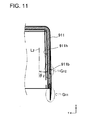
- the thickness of the first case member 911 and the second case member 912 is reduced to reduce the weight and size of the battery pack, it may be difficult to ensure interlocking strength. More specifically, for example, as shown in Fig. 10 , the side walls 911h, ... of the first case member 911 have a draft angle on the interior wall surface side. For this reason, in the case where the thickness of the first case member 911 and the second case member 912 is reduced to reduce the weight and size of the battery pack, it is necessary to reduce the thickness of protruding portions 911d, 911e, 911f and 911g, and the interlocking hooks 912a, 912b, .... Accordingly, their strength may be insufficient. This can be seen by an arrow G 11 of a cross-sectional view in Fig. 11 .
- the present invention is aimed at solving the aforementioned problem. It is an object of the present invention to provide a battery pack that can reduce manufacturing cost by interlocking case members with each other in assembling but can ensure sufficient interlocking strength between the case members even if the weight and size of the case member are reduced.
- the present invention provides a battery pack that has the following construction.
- the battery pack according to the present invention includes an exterior case and a base battery portion.
- the exterior case comprises first and second case members that are coupled to each other.
- the base battery portion is accommodated in the exterior case.
- the first and second case members have a bottom-closed hollow shape.
- the first and second case members are coupled to each other by interlocking of an interlocking hook with an interlocking opening.
- the interlocking hook and the interlocking opening are formed in opening end edge parts of the first and second case members.
- An interlocking structure portion of the first case member has an inner plate portion that extends in the opening end edge part along the opening interior side of a side wall of the first case member so that a groove portion is formed to sandwich an interlocking structure portion of the second case member between the side wall and the inner plate portion and to hold the interlocking structure portion of the second case member in the wall thickness direction.
- the side wall of the first case member has a draft angle on the interior side wall surface except for at least the part in that the interlocking structure portion is arranged, and the inclination angle of the interior wall surface of the inner plate portion in the interlocking structure portion in the first case member is smaller than the draft angle of the interior side wall surface.
- the interlocking structure portion of the first case member has the inner plate portion, which extends along the side wall.
- the interlocking structure portion of the second case member is sandwiched between the side wall and the inner plate portion of the first case member, and is thus held in the wall thickness in the groove portion between the side wall and the inner plate portion of the first case member.
- the battery pack according to the present invention since the first case member and second case member are coupled to each other by interlocking, as compared with the case where the first case member and second case member are coupled by using adhesive or supersonic vibration, the assembling process can be simplified. Therefore, the battery pack according to the present invention has an advantage from viewpoint of manufacturing cost. Also, according to the thus-constructed battery pack according to the present invention, since the inclination angle of the interior wall surface of the inner plate portion in the interlocking structure portion in the first case member is smaller than the draft angle of the interior side wall surface, the interior side wall surface can surely have a draft angle, and in addition to this the inner plate portion can have a sufficient thickness.
- the first case member can securely interlock with another member.
- the first case member has a draft angle on its the interior side wall surface, it is necessary neither to reduce space for accommodating the core pack (base battery portion) in order that the first case member can securely interlock with the second case member nor to increase the external shape of the first case member, but the first case member can interlock securely with the second case member.
- the interlocking structure portion can have a sufficient thickness. From this viewpoint, it is possible to ensure sufficient mechanical strength. For this reason, according to the battery pack of the present invention, it is possible to reduce manufacturing cost by interlocking case members with each other in assembling but can ensure sufficient interlocking strength between the case members even if the weight and size of the case member are reduced.
- the thus-constructed battery pack according to the present invention can optionally have the following construction.
- the opening end edge part of the side wall in the interlocking structure portion of the first case member can protrude toward the second case member, and a through hole as the interlocking opening can be formed penetrating the protruding part (side wall protruding portion) in the thickness direction of the side wall.
- the interlocking structure portion of the second case member can comprise the interlocking hook corresponding to the through hole (interlocking hole).
- the interlocking hook of the second case member interlocks with the hole arranged in the side wall protruding portion of the first case member. In this interlocking state, the inner plate portion in the first case member will press a surface of the second case member opposite to the surface with the interlocking hook. Therefore, this interlocking state cannot be easily disengaged by vibration from the outside.
- the inner plate portion of the first case member can have a hole as the interlocking opening that penetrates the inner plate portion in the thickness direction of the inner plate portion, and the interlocking hook can be arranged facing toward the opening interior side corresponding to the hole in the interlocking structure portion of the second case member.
- the second case member can have a slit that is arranged at a position corresponding to the inner plate portion of the first case member, and when a force is applied through the slit so that the inner plate portion deforms toward the opening interior side, the interlocking hook and the interlocking opening can be disengaged from each other.
- the first case member may not be decoupled from the second case member in the case users handle the battery pack in usual use
- the first case member can be disconnected from the second case member by using a dedicated tool to be inserted through the slit formed in the second case member in battery pack reclamation (reuse or recycling).
- battery pack reclamation reuse or recycling
- a part of the side wall exterior surface of the first case member can be recessed in the wall thickness direction of this side wall, and the inclination angle of the interior wall surface of the part corresponding to the recessed section (recessed part) in the side wall can be smaller than the draft angle of the interior side wall surface whereby increasing the thickness of this part. Since the thickness of the first case member is thus increased on the back side of the recessed section, it is possible to avoid increasing the entire size of the exterior case and additionally to ensure a sufficient thickness in this part. Therefore, this battery pack has an advantage from viewpoint of strength.
- the thickness of a part corresponding to the recessed portion 911b is small since the interior side wall surface of the first case member 911 has a draft angle (inclination angle ⁇ 2 with respect to a fictitious vertical line L 2 ).
- the part corresponding to the recessed portion 911b may have an insufficient strength when the thickness of the first case member is further reduced similar to the protruding portion (shown by the arrow G 11 ).
- the thickness of the first case member is increased on the back side of the recessed section by using space that is conventionally wasted due to the draft angle of the side wall, it is possible to ensure sufficient strength in the part corresponding to the recessed section without increasing the entire size of the exterior case.
- a window portion can be formed in the bottom of the recessed section to expose a display portion of an indicator, and a transparent film can be placed on the recessed section.
- Each of the first and second case members may be formed of separated members including the inner plate portion and the like after the separated members are separately formed and are then connected to each other.
- each of the first and second case members be integrally formed of a resin material.
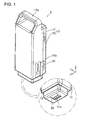
- Fig. 1 is a perspective view schematically showing the outward appearance of a battery pack 1 according to a first embodiment
- the battery pack 1 has a rectangular external shape that is elongated in the Z direction.
- the outward appearance of the battery pack 1 is formed by an exterior case 10.
- the exterior case 10 is composed of a first case member 11 and a second case member 12.
- the first case member 11 includes a grip portion 11a on the upper part in the Z direction. Users can grasp the grip portion 11a when mounting the battery pack 1 to a device or carrying the battery pack 1.
- the first case member 11 has a recessed portion 11b on a side surface on the front side in the Y direction.
- An LED portion cover film 21 is placed on the recessed portion 11b.
- an opening portion 11c is formed in the bottom wall of the first case member 11.
- An external connector 22 is exposed from the opening portion 11c.
- the battery pack 1 includes a core pack 30 that has a substantially rectangular parallelepiped shape, and is accommodated in internal accommodation space defined by the first case member 11 and the second case member 12.
- the core pack 30 includes a plurality of cylindrical base batteries 31, and a circuit board 32 as main components.
- the circuit board 32 is provided on a power transmission path between the base batteries 31 and the external connector 22. Lead lines between the circuit board 32 and the external connector 22 are not shown in Fig. 2 .
- the core pack 30 includes first and second holders 33 and 34, and lead plates 35, ... (lead plates arranged on the bottom side in the X direction are not show).
- the plurality of base batteries are sandwiched between the first and second holders 33 and 34 so that the first and second holders 33 and 34 hold the top and bottom parts of the base batteries in the X direction.
- the lead plates 35, ... electrically connect the plurality of base batteries 31 to each other.
- An LED portion 32a as indicator is mounted on the circuit board 32 as well as various types of electronic components.
- a window portion is formed on the bottom of the recessed portion 11b of the first case member 11. Light emitted from the LED portion 32a can outgo through the window portion.
- the LED portion cover film 21 has light transparency at least in a part corresponding to the window portion.
- the first case member 11 and the second case member 12 are coupled to each other by interlocking of interlocking hooks 12a, 12b ... with interlocking holes 11d1, 11e1, ....
- the interlocking hooks 12a, 12b ..., and interlocking holes 11d1, 11e1, ... are formed in opening end edges or a part in proximity to the opening end edges (opening end edge parts) of the first case member 11 and the second case member 12.
- the interlocking hole 11d1, 11e1, ... of the first case member 11 are formed in parts (protruding portions) 11d, 11e, ... that protrude downward from the opening end edge parts of the first case member 11 in the X direction (shown by arrows A 1 and A 2 ).
- the interlocking hooks 12a, 12b, ... of the second case member 12 are formed in the exterior surfaces of side walls of the second case member 12 (shown by arrows B 1 and B 2 ).
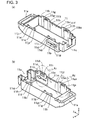
- first case member 11 The detailed construction of the first case member 11 is now described with reference to Figs. 3 and 4 .
- the first case member 11 four protruding portions 11d, 11e, 11f and 11g are arranged protruding upward from the opening end edge parts in the X direction.
- the interlocking hole 11d1, 11e1, 11f1 and 11g1 are formed in the protruding portions 11d, 11e, 11f and 11g, respectively.
- pairs of inner plate portions 11i1 and 11i2, 11j1 and 11j2, 11k1 and 11k2, and 11l1 and 11l2 are formed corresponding to the protruding portions 11d, 11e, 11f and 11g, respectively.
- the pairs of inner plate portions 11i1 and 11i2, 11j1 and 11j2, 11k1 and 11k2, and 11l1 and 11l2 are arranged along opening edges (Z direction) and on both the outsides of the interlocking holes 11d1, 11e1, 11f1 and 11g1, respectively.
- the inner plate portions are arranged on both the outsides of each interlocking hole.
- the inner plate portions have an elongated sheet shape that extends in the Z direction.
- groove portions are formed by the protruding portions 11d, 11e, 11f and 11g, and the corresponding pairs of inner plate portions 11i1 and 11i2. 11j1 and 11j2, 11k1 and 11k2. and 11l1 and 11l2.
- the groove portion is formed by each protruding portion and each pair of inner plate portions.
- Parts of the second case member 12 corresponding to the interlocking hooks 12a, 12b, ... are held in the groove portions in the wall thickness direction.
- the interior wall surface of a side wall 11h of the first case member 11 has a draft angle ⁇ 1 with respect to the X direction.
- the interior wall surface of the side wall 11h of the first case member 11 has a draft angle so that the interior width of the first case member 11 gets wider from the bottom toward the opening end edge parts.
- the interior wall surfaces of the inner plate portion 11j1, ... of the first case member 11 have an inclination angle smaller than the draft angle of the interior wall surface 11h of the aforementioned side wall.
- the inclination angle of the inner plate portions 11j1, ... is substantially 0°.
- the inner plate portions 11j1, ... are substantially parallel to the depth direction axis L 1 of the first case member 11 extending along the X axis.
- the battery pack 1 maximizes effective use of space of the interior surface parts of the case side walls, which are wasted due to the draft angle in the conventionally-designed exterior case, so that the inner plate portions 11i1, 11i2, 11j1. 11j2. 11k1, 11k2, 11l1 and 11l2 are arranged in these parts.
- the interlocking holes 11d1, 11e1, 11f1 and 11g1 of the first case member 11 cannot be easily disengaged (unlocked) from the interlocking hooks 12a, 12b, ... of the second case member 12 by vibration from the outside, or the like.
- the inner plate portions 11i1, 11i2. 11j1, 11j2, 11k1, 11k2. 11l1 and 11l2 are thus arranged, it is possible to surely provide the draft angle to the side walls and additionally to ensure the mechanical strength of the inner plate portions 11i1, 11i2, 11j1, 11j2, 11k1, 11k2, 11l1 and 11l2.
- the inner plate portions 11i1, 11i2, 11j1, 11j2, 11k1, 11k2, 11l1 and 11l2 are arranged in proximity to the protruding portions 11d, 11e, 11f and 11g, it is possible to provide an effect in that the side walls are mechanically reinforced.
- the battery pack 1 maximizes effective use of space corresponding to the draft angle of the side wall interior surfaces in the first case member 11 to form the inner plate portions 11i1, 11i2, 11j1, 11j2, 11k1, 11k2, 11l1 and 11l2, the external size of the first case member 11 is not increased.
- a thicker portion 11n is formed on a back surface (interior side surface) part of the side wall corresponding to the recessed portion 11b (shown by the arrow A 1 in Fig. 3(b) ).
- the thicker portion 11n is also formed by reducing the inclination angle of the interior surface to an angle smaller than the draft angle of the interior wall surface 11h of the aforementioned side wall similarly to the inner plate portions 11i1, 11i2, 11j1, 11j2, 11k1, 11k2, 11l1 and 11l2. Accordingly, as shown in Fig. 4(b) , in the battery pack 1, the thickness (wall thickness t) of the back surface part of the recessed portion 11b can be increased without increasing the external size of the first case member 11. Therefore, it is possible to improve the strength of the first case member 11.
- the window portion 11b1 is formed in the recessed portion 11b to externally expose the LED portion, since the recessed portion 11b is reinforced by the thicker portion 11n, problems will not arise in mechanical strength.
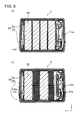
- space remains between the interior wall surfaces 11h, 11m, ... of the first case member 11 and the second case member 12, and the core pack 30 in areas at least except for interlocking structure portions (interlocking holes 11d1, 11e1, 11f1 and 11g1, and interlocking hooks 12a, 12b, ...) of the side wall of the first case member 11 and the second case member 12.
- interlocking structure portions interlocking holes 11d1, 11e1, 11f1 and 11g1, and interlocking hooks 12a, 12b, .
- the inner plate portions 11i1, 11i2, 11j1, 11j2. 11k1. 11k2, 11l1 and 11l2 the interior wall surfaces of which have a smaller inclination angle are arranged in areas in that the interlocking structure portions (interlocking holes 11d1, 11e1, 11f1 and 11g1) of the first case member 11 are formed. Since the inner plate portions 11i1, 11i2, 11j1, 11j2, 11k1, 11k2, 11l1 and 11l2 are formed in space corresponding to the draft angle of the interior wall surfaces of the side walls, it is possible to improve the mechanical strength of the side walls and interlocking strength without increasing the external size of the exterior case 10.
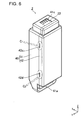
- a battery pack 2 according to a second embodiment is now described with reference to Figs. 6 to 8 .
- an exterior case 40 is composed of a first case member 41 and a second case member 42, similarly to the aforementioned battery pack 1.
- the first case member 41 has a grip portion 41a and an opening portion 41c.
- slits 42c and 42d are formed in a side wall of the second case member 42 (shown by arrows C 1 and C 2 ).
- interlocking holes are not formed in an opening end edge part 41g of a side wall 41h of the first case member 41, but an interlocking hole 4111 is formed in an inner plate portion 41l that is formed on the interior side of the side wall 41h in the Y direction.
- an interlocking hook 42b of the second case member 42 protrudes toward the case interior side, and interlocks with the interlocking hole 4111, which is formed in the inner plate portion 41l of the first case member 41.
- the slit 42d is opened directly above the interlocking hook 42b of the second case member 42 in the X direction.
- the slit 42d penetrates the side wall of the second case member 42 in the thickness direction.
- the upper part of the inner plate portion 41l relative to the interlocking hole 41l1 in the X direction is located inside the slit 42d in the Y direction and is exposed through the slit 42d.
- the slit 42d is sealed by the inner plate portion 41l of the first case member 41, which is located inside the slit 42d so that dust, moisture and the like cannot enter the interior of the exterior case 41.
- the exterior case 40 is composed of the first case member 41 and the second case member 42 interlocking with each other. Specifically, the interlocking hook 42b of the first case member 41 interlocks with the interlocking hole 4111 formed in the inner plate portion 41l of the second case member 42.
- the opening end edge part 41g of the first case member 41 presses a part of the opening end edge part of the second case member 42 corresponding to the back of the interlocking hook 42b. Accordingly, users who use the battery pack 2 may not disassemble the package (exterior case 40). For example, recycling or reuse of used battery pack 2 can be taken into consideration. Some parts of used battery pack 2 may be replaced in reuse. In this case, the manufacturer, recycling manufacturer or the like has to disassemble the exterior case 40 after reclaiming battery packs 2 from users. In this case, it is preferable to maximize reuse of the exterior case 40. From this viewpoint, in the battery pack 2, the exterior case 40 has the slit 42d to maximize reuse of the exterior case 40 when be disassembled.
- force F is applied to the inner plate portion 41l by using a dedicated tool through the slit 42d to press (bend) the inner plate portion 41l inward.
- the interlocking hook 42b can be disengaged from the interlocking hole 41l1.
- the first case member 41 can be decoupled from the second case member 42 without breakage of the interlocking hook 42b or the interlocking hole 4111 of the inner plate portion 41l.
- the inner plate portion 41l will return to the original position by its elasticity.
- the first case member 41 and the second case member 42 can be reused. Since the draft angle of the side wall 41h of the first case member 41 or the second case member 42, and the inclination angle of the inner plate portion 41l have the same relationship as the foregoing first embodiment, description of the relationship is omitted. For this reason, according to the battery pack 2 of this embodiment, it is possible to reduce manufacturing cost by interlocking the case members 41 and 42 with each other in assembling but can ensure sufficient interlocking strength between the case members 41 and 42 even if the weight and size of the case members 41 and 42 are reduced.
- the outward appearance shape of a battery pack is not limited to this.
- the outward appearance shape may be flatter or may be cylindrical or disk-shaped.
- each of the first case members 11 and 41, and each of the second case members 12 and 42 are integrally formed of a resin material by molding, the material and the formation process are limited to resin and molding.
- a metal material, a ceramic material, or the like may be used as the material of the case member.
- a plurality of parts may be coupled to each other to form each case member.
- a metal plate or the like may be partially used in an interlocking part to reinforce this part.
- interlocking holes 11d1, 11e1, 11f1, 11g1 and 41l1 have been described that are formed in the first case members 11 and 41
- the interlocking hooks 12a, 12b and 42b have been described that are formed in the second case members 12 and 42
- the interlocking holes and the interlocking hooks can be formed in the second case member and the first case member, respectively.
- a case member that has interlocking hooks may include plate portions such as the inner plate portions in parallel to a wall surface of the case member. Also, in this case the same effect can be provided.
- the base batteries 31 included in the core pack 30 have been described as cylindrical batteries as shown in Fig. 2
- the outward appearance shape and the type of the base batteries are not specifically limited.
- rectangular shaped batteries can be used.
- various batteries can be used such as nickel cadmium (Ni-Cd) rechargeable battery, nickel metal hydride (Ni-MH) rechargeable battery, and lithium ion (Li-ion) rechargeable battery.
- opening end edge part interlocking structure portion of the first case member 11
- the protruding portions are not always required.
- the opening end edge part can be constructed as in the second embodiment as shown in Figs. 7 and 8 .
- the interior wall surfaces of the inner plate portions 11i1, 11i2, 11j1, 11j2, 11k1, 11k2, 11l1, 11l2 and 41l have been described that extend substantially in the vertical direction (substantially parallel to the X direction), the interior wall surfaces of the inner plate portions 11i1, 11i2, 11j1, 11j2, 11k1. 11k2. 11l1, 11l2 and 41l are not always required to extend substantially in the vertical direction.
- the interior wall surfaces of the inner plate portions are only required to have an inclination angle smaller than the draft angle of the interior wall surfaces 11h, 11m, 41h, ... of side walls.
- the exterior wall surfaces of the side walls of the first case members 11 and 41, and the second case members 12 and 42 are not limited to whether they have a draft angle or not.
- the exterior wall surfaces of the side walls of the first case members 11 and 41, and the second case members 12 and 42 may not have a draft angle.
- removal measurements are required in the formation process of the case members 11, 12, 41 and 42.
- slidable molds are required corresponding to the exterior wall surfaces of the side walls. This will increase manufacturing cost (mold cost).
- the exterior wall surfaces of the side walls of the first case members 11 and 41, and the second case members 12 and 42 can have the same draft angle as or greater than the interior wall surfaces 11h, 11m, 41h, ....
- the interior wall surfaces 11h, 11m, 41h, ... can have a draft angle of 0.5°
- the exterior wall surfaces can have a draft angle of about 1° to 2°.
- the construction of molds can be simple. Therefore, there is an advantage from viewpoint of manufacturing cost.
- the interior wall surfaces 11h, 11m, 41h, ... and the exterior wall surfaces have a draft angle of 2°, even if the depth of the case member is large, thickness variation can be suppressed.
- the present invention is useful to provide a battery pack as power supply for power assisted electric bicycle, HEV, PEV, and the like.
Landscapes
- Chemical & Material Sciences (AREA)
- Chemical Kinetics & Catalysis (AREA)
- Electrochemistry (AREA)
- General Chemical & Material Sciences (AREA)
- Battery Mounting, Suspending (AREA)
Abstract
A first case 11 includes protruding portions 11d to 11g on an opening end edge parts. Interlocking holes 11d1 to 11g1 are formed in the protruding portions 11d to 11g, respectively. Pairs of inner plates 11i1 to 11l2 are arranged on opening interior parts of the protruding portions 11d to 11g, respectively. Interlocking hooks of a second case are sandwiched between the protruding portions 11d to 11g, and the pairs of inner plates 11i1 to 11l2, and are held in the thickness direction, when the first and second cases interlocks with each other. The side wall 11h of the first case 11 has a draft on the interior side wall surface except for at least parts in that the inner plates 11i1 to 11l2 are arranged. The interior wall surfaces of the inner plates 11i1 to 11l2 have an inclination angle smaller than the draft of the wall portion 11h.
Description
- The present invention relates to a battery pack, and in particular to a battery pack that includes two case members that are coupled to each other by an interlocking structure to compose an exterior case.
- In recent years, battery packs have been widely used as a power supply in notebook personal computer (notebook PC) and power tool as well as power assisted electric bicycle, hybrid electric vehicle (HEV), and electric vehicle (PEV).
For example, as shown inFig. 9 , a battery pack includes an exterior case composed of first andsecond case members core pack 930 accommodated in the exterior case. Thefirst case member 911 located on the upper side in the Z direction includes agrip portion 911a, an indicator fit-inportion 911b, anopening 911c for accommodating anexternal connector 922, and the like. - The
core pack 930 include a plurality of base batteries (cylindrical rechargeable batteries) 931,holders circuit board substrate 932 that is arranged on the front side in the Y direction, andlead plates 935, ... that connect thebase batteries 931 to each other. Also, thecircuit board 932 and theexternal connector 922 are connected to each other by lead lines (not shown).
In addition, anindicator display portion 932a is arranged on thecircuit board 932. Thedisplay portion 932a is visible for users through a window portion that opens on the bottom of therecessed portion 911b of thefirst case member 911. Atransparent film 921 is placed on therecessed portion 911b of thefirst case member 911, and closes the window portion to prevent that moisture and dust enters the battery pack. - Cost reduction of battery packs is required. Accordingly, various efforts are under way to reduce battery pack cost. For example, as shown in
Fig. 9 , instead of adhesive or supersonic vibration jointing method or the like, thefirst case member 911 and thesecond case member 912 have been designed to be assembled by interlocking of interlocking holes 911d1 and 911e1 arranged in protrudingportions hooks Fig. 10 , thefirst case member 911forms protruding portions first case member 911. According to this design, the number of man-hours in manufacturing and cycle time can be reduced. Accordingly, it is possible to reduce manufacturing cost. - See Japanese Patent Laid-Open Publications Nos.
2003-123715 2008-140730 - However, in the case where the
first case member 911 and thesecond case member 912 are assembled by the interlocking, if the thickness of thefirst case member 911 and thesecond case member 912 is reduced to reduce the weight and size of the battery pack, it may be difficult to ensure interlocking strength.
More specifically, for example, as shown inFig. 10 , theside walls 911h, ... of thefirst case member 911 have a draft angle on the interior wall surface side. For this reason, in the case where the thickness of thefirst case member 911 and thesecond case member 912 is reduced to reduce the weight and size of the battery pack, it is necessary to reduce the thickness of protrudingportions hooks
Accordingly, their strength may be insufficient. This can be seen by an arrow G11 of a cross-sectional view inFig. 11 . - The present invention is aimed at solving the aforementioned problem. It is an object of the present invention to provide a battery pack that can reduce manufacturing cost by interlocking case members with each other in assembling but can ensure sufficient interlocking strength between the case members even if the weight and size of the case member are reduced.
- To achieve the aforementioned object, the present invention provides a battery pack that has the following construction.
The battery pack according to the present invention includes an exterior case and a base battery portion. The exterior case comprises first and second case members that are coupled to each other. The base battery portion is accommodated in the exterior case.
The first and second case members have a bottom-closed hollow shape. The first and second case members are coupled to each other by interlocking of an interlocking hook with an interlocking opening. The interlocking hook and the interlocking opening are formed in opening end edge parts of the first and second case members. An interlocking structure portion of the first case member has an inner plate portion that extends in the opening end edge part along the opening interior side of a side wall of the first case member so that a groove portion is formed to sandwich an interlocking structure portion of the second case member between the side wall and the inner plate portion and to hold the interlocking structure portion of the second case member in the wall thickness direction. - In addition, in the thus-constructed battery pack according to the present invention, the side wall of the first case member has a draft angle on the interior side wall surface except for at least the part in that the interlocking structure portion is arranged, and the inclination angle of the interior wall surface of the inner plate portion in the interlocking structure portion in the first case member is smaller than the draft angle of the interior side wall surface.
- In the battery pack related to the present invention, the interlocking structure portion of the first case member has the inner plate portion, which extends along the side wall. The interlocking structure portion of the second case member is sandwiched between the side wall and the inner plate portion of the first case member, and is thus held in the wall thickness in the groove portion between the side wall and the inner plate portion of the first case member. According to the thus-constructed battery pack according to the present invention, once the interlocking structure portion of the first case member interlocks with the interlocking structure portion of the second case member, the interlocking structure portions are resistant to disengagement even when being subjected to vibration or the like. The reason is that the interlocking structure portion of the second case member is held in the groove portion of the interlocking structure portion of the first case member.
- In addition, in the battery pack according to the present invention, since the first case member and second case member are coupled to each other by interlocking, as compared with the case where the first case member and second case member are coupled by using adhesive or supersonic vibration, the assembling process can be simplified. Therefore, the battery pack according to the present invention has an advantage from viewpoint of manufacturing cost.
Also, according to the thus-constructed battery pack according to the present invention, since the inclination angle of the interior wall surface of the inner plate portion in the interlocking structure portion in the first case member is smaller than the draft angle of the interior side wall surface, the interior side wall surface can surely have a draft angle, and in addition to this the inner plate portion can have a sufficient thickness. For this reason, even in the case where the thickness of the first case member is reduced to reduce the weight and size of the first case member, the first case member can securely interlock with another member. In addition, since the first case member has a draft angle on its the interior side wall surface, it is necessary neither to reduce space for accommodating the core pack (base battery portion) in order that the first case member can securely interlock with the second case member nor to increase the external shape of the first case member, but the first case member can interlock securely with the second case member. - In addition, in the battery pack related to the present invention, since the inclination angle of the interior wall surface is small, the interlocking structure portion can have a sufficient thickness. From this viewpoint, it is possible to ensure sufficient mechanical strength.
For this reason, according to the battery pack of the present invention, it is possible to reduce manufacturing cost by interlocking case members with each other in assembling but can ensure sufficient interlocking strength between the case members even if the weight and size of the case member are reduced. - The thus-constructed battery pack according to the present invention can optionally have the following construction.
In the battery pack according to the present invention, the opening end edge part of the side wall in the interlocking structure portion of the first case member can protrude toward the second case member, and a through hole as the interlocking opening can be formed penetrating the protruding part (side wall protruding portion) in the thickness direction of the side wall. In addition, in the battery pack according to the present invention, the interlocking structure portion of the second case member can comprise the interlocking hook corresponding to the through hole (interlocking hole). In this construction, the interlocking hook of the second case member interlocks with the hole arranged in the side wall protruding portion of the first case member. In this interlocking state, the inner plate portion in the first case member will press a surface of the second case member opposite to the surface with the interlocking hook. Therefore, this interlocking state cannot be easily disengaged by vibration from the outside. - In the battery pack according to the present invention, the inner plate portion of the first case member can have a hole as the interlocking opening that penetrates the inner plate portion in the thickness direction of the inner plate portion, and the interlocking hook can be arranged facing toward the opening interior side corresponding to the hole in the interlocking structure portion of the second case member. In addition, in the battery pack according to the present invention, the second case member can have a slit that is arranged at a position corresponding to the inner plate portion of the first case member, and when a force is applied through the slit so that the inner plate portion deforms toward the opening interior side, the interlocking hook and the interlocking opening can be disengaged from each other.
- According to the thus-constructed battery pack of the present invention, although the first case member may not be decoupled from the second case member in the case users handle the battery pack in usual use, the first case member can be disconnected from the second case member by using a dedicated tool to be inserted through the slit formed in the second case member in battery pack reclamation (reuse or recycling). For this reason, in this construction, it is possible to easily disassemble the package and to reuse or recycle used battery packs after reclamation. Therefore, this battery pack has an advantage from viewpoint of ecology.
- In the battery pack according to the present invention, in addition to the aforementioned construction, a part of the side wall exterior surface of the first case member can be recessed in the wall thickness direction of this side wall, and the inclination angle of the interior wall surface of the part corresponding to the recessed section (recessed part) in the side wall can be smaller than the draft angle of the interior side wall surface whereby increasing the thickness of this part. Since the thickness of the first case member is thus increased on the back side of the recessed section, it is possible to avoid increasing the entire size of the exterior case and additionally to ensure a sufficient thickness in this part. Therefore, this battery pack has an advantage from viewpoint of strength.
- That is, as shown in
Fig. 11 , in the conventionally-designed battery pack, which has therecessed portion 911b (show by an arrow G12) arranged in a part of side wall exterior surface of thefirst case member 911, the thickness of a part corresponding to therecessed portion 911b is small since the interior side wall surface of thefirst case member 911 has a draft angle (inclination angle Θ2 with respect to a fictitious vertical line L2). For this reason, the part corresponding to therecessed portion 911b may have an insufficient strength when the thickness of the first case member is further reduced similar to the protruding portion (shown by the arrow G11). Contrary to this, since the thickness of the first case member is increased on the back side of the recessed section by using space that is conventionally wasted due to the draft angle of the side wall, it is possible to ensure sufficient strength in the part corresponding to the recessed section without increasing the entire size of the exterior case. - In addition to the thus-constructed battery pack, a window portion can be formed in the bottom of the recessed section to expose a display portion of an indicator, and a transparent film can be placed on the recessed section.
Each of the first and second case members may be formed of separated members including the inner plate portion and the like after the separated members are separately formed and are then connected to each other. However, in the battery pack according to the present invention, from viewpoint of manufacturing cost including parts management cost, it is preferable that each of the first and second case members be integrally formed of a resin material.
The above and further objects of the present invention as well as the features thereof will become more apparent from the following detailed description to be made in conjunction with the accompanying drawings. -
Fig. 1 is a perspective view schematically showing the outward appearance of abattery pack 1 according to a first embodiment; -
Fig. 2 is a developed perspective view schematically showing the internal construction of thebattery pack 1; -
Fig. 3 is a perspective view schematically showing the construction of afirst case member 11 of thebattery pack 1; -
Fig. 4 is a cross-sectional view schematically showing the construction of an opening end of thefirst case member 11; -
Fig. 5 is a cross-sectional view schematically showing the interlocking construction between thefirst case member 11 and thesecond case member 12; -
Fig. 6 is a perspective view schematically showing the outward appearance of abattery pack 2 according to a second embodiment; -
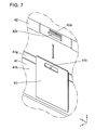
Fig. 7 is a perspective view schematically showing the interlocking construction between thefirst case member 41 and thesecond case member 42 in thebattery pack 2; -
Fig. 8 is a perspective view (partially sectional view) schematically showing operating procedure that disengages thefirst case member 41 and thesecond case member 42 from each other; -
Fig. 9 is a developed perspective view schematically showing the construction of a conventionally-designed battery pack; -
Fig. 10 is a perspective view schematically showing the construction of afirst case member 911 of the conventionally-designed battery pack; and -
Fig. 11 is a cross-sectional view schematically showing a part of the construction of thefirst case member 911 of the conventionally-designed battery pack. - The following description will describe embodiments according to the present invention with reference to the drawings. It should be appreciated, however, that the embodiments and modified embodiments described below are illustrations to give a concrete form to technical ideas of the invention for sake of understanding the construction and the working effects of the present invention, the present invention is not specifically limited to the embodiments except for essential elements.
- The outward appearance of a
battery pack 1 according to a first embodiment is now described with reference toFig. 1 . - As shown in
Fig. 1 , thebattery pack 1 has a rectangular external shape that is elongated in the Z direction. The outward appearance of thebattery pack 1 is formed by anexterior case 10. Theexterior case 10 is composed of afirst case member 11 and asecond case member 12.
Thefirst case member 11 includes agrip portion 11a on the upper part in the Z direction. Users can grasp thegrip portion 11a when mounting thebattery pack 1 to a device or carrying thebattery pack 1. Also, thefirst case member 11 has a recessedportion 11b on a side surface on the front side in the Y direction. An LEDportion cover film 21 is placed on the recessedportion 11b. - As shown in a part enclosed by a two-point dashed line in
Fig. 1 , anopening portion 11c is formed in the bottom wall of thefirst case member 11. Anexternal connector 22 is exposed from the openingportion 11c. - The internal construction of the
battery pack 1 is now described with reference toFig. 2 .
As shown inFig. 2 , in thebattery pack 1 includes acore pack 30 that has a substantially rectangular parallelepiped shape, and is accommodated in internal accommodation space defined by thefirst case member 11 and thesecond case member 12. Thecore pack 30 includes a plurality ofcylindrical base batteries 31, and acircuit board 32 as main components. Thecircuit board 32 is provided on a power transmission path between thebase batteries 31 and theexternal connector 22. Lead lines between thecircuit board 32 and theexternal connector 22 are not shown inFig. 2 . - In addition, the
core pack 30 includes first andsecond holders plates 35, ... (lead plates arranged on the bottom side in the X direction are not show). The plurality of base batteries are sandwiched between the first andsecond holders second holders lead plates 35, ... electrically connect the plurality ofbase batteries 31 to each other.
AnLED portion 32a as indicator is mounted on thecircuit board 32 as well as various types of electronic components. A window portion is formed on the bottom of the recessedportion 11b of thefirst case member 11. Light emitted from theLED portion 32a can outgo through the window portion. The LEDportion cover film 21 has light transparency at least in a part corresponding to the window portion. - The
first case member 11 and thesecond case member 12 are coupled to each other by interlocking of interlockinghooks first case member 11 and thesecond case member 12. The interlocking hole 11d1, 11e1, ... of thefirst case member 11 are formed in parts (protruding portions) 11d, 11e, ... that protrude downward from the opening end edge parts of thefirst case member 11 in the X direction (shown by arrows A1 and A2). - The interlocking hooks 12a, 12b, ... of the
second case member 12 are formed in the exterior surfaces of side walls of the second case member 12 (shown by arrows B1 and B2). - The detailed construction of the
first case member 11 is now described with reference toFigs. 3 and4 .
As shown inFigs. 3(a) and 3(b) , in thefirst case member 11, four protrudingportions portions - Also, in the
first case member 11, as shown inFigs. 3(a) and 3(b) , pairs of inner plate portions 11i1 and 11i2, 11j1 and 11j2, 11k1 and 11k2, and 11l1 and 11l2 are formed corresponding to the protrudingportions - In the
first case member 11, groove portions are formed by the protrudingportions second case member 12 corresponding to the interlocking hooks 12a, 12b, ... are held in the groove portions in the wall thickness direction.
In consideration of manufacture process, as shown inFig. 4(a) , the interior wall surface of aside wall 11h of thefirst case member 11 has a draft angle Θ1 with respect to the X direction. That is, in order to facilitate removal of thefirst case member 11 from a mold in resin molding, the interior wall surface of theside wall 11h of thefirst case member 11 has a draft angle so that the interior width of thefirst case member 11 gets wider from the bottom toward the opening end edge parts. - As shown in
Fig. 4(a) , in thebattery pack 1 according to this embodiment, the interior wall surfaces of the inner plate portion 11j1, ... of thefirst case member 11 have an inclination angle smaller than the draft angle of theinterior wall surface 11h of the aforementioned side wall. Specifically, the inclination angle of the inner plate portions 11j1, ... is substantially 0°. Thus, the inner plate portions 11j1, ... are substantially parallel to the depth direction axis L1 of thefirst case member 11 extending along the X axis. - The
battery pack 1 according to this embodiment maximizes effective use of space of the interior surface parts of the case side walls, which are wasted due to the draft angle in the conventionally-designed exterior case, so that the inner plate portions 11i1, 11i2, 11j1. 11j2. 11k1, 11k2, 11l1 and 11l2 are arranged in these parts. Thus, the interlocking holes 11d1, 11e1, 11f1 and 11g1 of thefirst case member 11 cannot be easily disengaged (unlocked) from the interlocking hooks 12a, 12b, ... of thesecond case member 12 by vibration from the outside, or the like. - Since the inner plate portions 11i1, 11i2. 11j1, 11j2, 11k1, 11k2. 11l1 and 11l2 are thus arranged, it is possible to surely provide the draft angle to the side walls and additionally to ensure the mechanical strength of the inner plate portions 11i1, 11i2, 11j1, 11j2, 11k1, 11k2, 11l1 and 11l2.
In addition, since the inner plate portions 11i1, 11i2, 11j1, 11j2, 11k1, 11k2, 11l1 and 11l2 are arranged in proximity to the protrudingportions battery pack 1 maximizes effective use of space corresponding to the draft angle of the side wall interior surfaces in thefirst case member 11 to form the inner plate portions 11i1, 11i2, 11j1, 11j2, 11k1, 11k2, 11l1 and 11l2, the external size of thefirst case member 11 is not increased. - As shown in
Fig. 3(a) and 3(b) , athicker portion 11n is formed on a back surface (interior side surface) part of the side wall corresponding to the recessedportion 11b (shown by the arrow A1 inFig. 3(b) ). Thethicker portion 11n is also formed by reducing the inclination angle of the interior surface to an angle smaller than the draft angle of theinterior wall surface 11h of the aforementioned side wall similarly to the inner plate portions 11i1, 11i2, 11j1, 11j2, 11k1, 11k2, 11l1 and 11l2. Accordingly, as shown inFig. 4(b) , in thebattery pack 1, the thickness (wall thickness t) of the back surface part of the recessedportion 11b can be increased without increasing the external size of thefirst case member 11. Therefore, it is possible to improve the strength of thefirst case member 11. - As shown in
Fig. 4(b) , although the window portion 11b1 is formed in the recessedportion 11b to externally expose the LED portion, since the recessedportion 11b is reinforced by thethicker portion 11n, problems will not arise in mechanical strength. - Interlocking of the
first case member 11 with thesecond case member 12 is now described with reference toFig. 5 . - At first, as shown in
Fig. 5(a) , space remains between the interior wall surfaces 11h, 11m, ... of thefirst case member 11 and thesecond case member 12, and thecore pack 30 in areas at least except for interlocking structure portions (interlocking holes 11d1, 11e1, 11f1 and 11g1, andinterlocking hooks first case member 11 and thesecond case member 12. The reason is that the interior wall surfaces 11h, 11m, ... of the side walls of thefirst case member 11 and thesecond case member 12 have the draft angle. - On the other hand, as shown in
Fig. 5(b) , the inner plate portions 11i1, 11i2, 11j1, 11j2. 11k1. 11k2, 11l1 and 11l2 the interior wall surfaces of which have a smaller inclination angle are arranged in areas in that the interlocking structure portions (interlocking holes 11d1, 11e1, 11f1 and 11g1) of thefirst case member 11 are formed. Since the inner plate portions 11i1, 11i2, 11j1, 11j2, 11k1, 11k2, 11l1 and 11l2 are formed in space corresponding to the draft angle of the interior wall surfaces of the side walls, it is possible to improve the mechanical strength of the side walls and interlocking strength without increasing the external size of theexterior case 10. - A
battery pack 2 according to a second embodiment is now described with reference toFigs. 6 to 8 . - As shown in
Fig. 6 , also in thebattery pack 2, anexterior case 40 is composed of afirst case member 41 and asecond case member 42, similarly to theaforementioned battery pack 1. Similarly, thefirst case member 41 has agrip portion 41a and anopening portion 41c. - In the
battery pack 2 according to this embodiment, slits 42c and 42d are formed in a side wall of the second case member 42 (shown by arrows C1 and C2). - As shown in
Fig. 7 , in thebattery pack 2, interlocking holes are not formed in an openingend edge part 41g of aside wall 41h of thefirst case member 41, but aninterlocking hole 4111 is formed in an inner plate portion 41l that is formed on the interior side of theside wall 41h in the Y direction. Correspondingly, an interlockinghook 42b of thesecond case member 42 protrudes toward the case interior side, and interlocks with theinterlocking hole 4111, which is formed in the inner plate portion 41l of thefirst case member 41. - As shown in
Fig. 7 , theslit 42d is opened directly above the interlockinghook 42b of thesecond case member 42 in the X direction. Theslit 42d penetrates the side wall of thesecond case member 42 in the thickness direction. After thefirst case member 41 is coupled to thesecond case member 42, the upper part of the inner plate portion 41l relative to the interlocking hole 41l1 in the X direction is located inside theslit 42d in the Y direction and is exposed through theslit 42d. In other words, theslit 42d is sealed by the inner plate portion 41l of thefirst case member 41, which is located inside theslit 42d so that dust, moisture and the like cannot enter the interior of theexterior case 41. - Interlocking/disengagement of the
first case member 41 with/from thesecond case member 42 are now described with reference toFig. 8 .
As shown inFig. 8(a) , theexterior case 40 is composed of thefirst case member 41 and thesecond case member 42 interlocking with each other. Specifically, the interlockinghook 42b of thefirst case member 41 interlocks with theinterlocking hole 4111 formed in the inner plate portion 41l of thesecond case member 42. - After the
interlocking hook 42b interlocks with theinterlocking hole 4111, the openingend edge part 41g of thefirst case member 41 presses a part of the opening end edge part of thesecond case member 42 corresponding to the back of the interlockinghook 42b. Accordingly, users who use thebattery pack 2 may not disassemble the package (exterior case 40).
For example, recycling or reuse of usedbattery pack 2 can be taken into consideration. Some parts of usedbattery pack 2 may be replaced in reuse.
In this case, the manufacturer, recycling manufacturer or the like has to disassemble theexterior case 40 after reclaimingbattery packs 2 from users.
In this case, it is preferable to maximize reuse of theexterior case 40. From this viewpoint, in thebattery pack 2, theexterior case 40 has theslit 42d to maximize reuse of theexterior case 40 when be disassembled. - That is, as shown in
Fig. 8(b) , force F is applied to the inner plate portion 41l by using a dedicated tool through theslit 42d to press (bend) the inner plate portion 41l inward. Thus, the interlockinghook 42b can be disengaged from the interlocking hole 41l1. Accordingly, thefirst case member 41 can be decoupled from thesecond case member 42 without breakage of the interlockinghook 42b or theinterlocking hole 4111 of the inner plate portion 41l. - After the
first case member 41 is decoupled from thesecond case member 42, the inner plate portion 41l will return to the original position by its elasticity. Thus, thefirst case member 41 and thesecond case member 42 can be reused.
Since the draft angle of theside wall 41h of thefirst case member 41 or thesecond case member 42, and the inclination angle of the inner plate portion 41l have the same relationship as the foregoing first embodiment, description of the relationship is omitted. For this reason, according to thebattery pack 2 of this embodiment, it is possible to reduce manufacturing cost by interlocking thecase members case members case members - In the foregoing first and second embodiments, although the battery packs 1 and 2 have been illustratively described that have an outward appearance of substantially rectangular parallelepiped shape, the outward appearance shape of a battery pack is not limited to this. For example, the outward appearance shape may be flatter or may be cylindrical or disk-shaped.
In the foregoing first and second embodiments, although each of thefirst case members second case members - In the foregoing first and second embodiments, although the interlocking holes 11d1, 11e1, 11f1, 11g1 and 41l1 have been described that are formed in the
first case members second case members - In the foregoing first and second embodiments, although the
base batteries 31 included in thecore pack 30 have been described as cylindrical batteries as shown inFig. 2 , the outward appearance shape and the type of the base batteries are not specifically limited. For example, rectangular shaped batteries can be used. Also, various batteries can be used such as nickel cadmium (Ni-Cd) rechargeable battery, nickel metal hydride (Ni-MH) rechargeable battery, and lithium ion (Li-ion) rechargeable battery. - In the foregoing first embodiment, although a part of opening end edge part (interlocking structure portion) of the
first case member 11 has been describe that protrudes toward the second case member 12 (protrudingportion Figs. 7 and8 .
In the foregoing first and second embodiments, although the interior wall surfaces of the inner plate portions 11i1, 11i2, 11j1, 11j2, 11k1, 11k2, 11l1, 11l2 and 41l have been described that extend substantially in the vertical direction (substantially parallel to the X direction), the interior wall surfaces of the inner plate portions 11i1, 11i2, 11j1, 11j2, 11k1. 11k2. 11l1, 11l2 and 41l are not always required to extend substantially in the vertical direction. The interior wall surfaces of the inner plate portions are only required to have an inclination angle smaller than the draft angle of the interior wall surfaces 11h, 11m, 41h, ... of side walls. - In the foregoing first and second embodiments, the exterior wall surfaces of the side walls of the
first case members second case members first case members second case members case members - Alternatively, the exterior wall surfaces of the side walls of the
first case members second case members - The present invention is useful to provide a battery pack as power supply for power assisted electric bicycle, HEV, PEV, and the like.
Claims (6)
- A battery pack comprising:an exterior case comprising first and second case members coupled to each other; anda base battery portion that is accommodated in the exterior case,
whereinsaid first and second case members have a bottom-closed hollow shape, and are coupled to each other by interlocking of an interlocking hook with an interlocking opening, wherein the interlocking hook is formed in an opening end edge part of one of said first and second case members, and the interlocking opening is formed in an opening end edge part of the other of said first and second case members, characterized in thatan interlocking structure portion of said first case member has an inner plate portion that extends in said opening end edge part along the opening interior side of a side wall of said first case member so that a groove portion is formed to sandwich an interlocking structure portion of said second case member between said side wall and said inner plate portion and to hold the interlocking structure portion of said second case member in the wall thickness direction,wherein said side wall of said first case member has a draft angle on the interior side wall surface except for at least the part in that said interlocking structure portion is arranged,wherein the inclination angle of the interior wall surface of said inner plate portion in said interlocking structure portion in said first case member is smaller than the draft angle of said interior side wall surface. - The battery pack according to claim 1,
wherein said opening end edge part of said side wall in said interlocking structure portion of said first case member protrudes toward said second case member, and a through hole as said interlocking opening is formed penetrating the protruding part in the thickness direction of said side wall, and
wherein said interlocking structure portion of said second case member has said interlocking hook corresponding to said hole. - The battery pack according to claim 1, wherein said inner plate portion of said first case member has a through hole as said interlocking opening that penetrates said inner plate portion in the thickness direction of said inner plate portion, wherein said interlocking structure portion of said second case member has interlocking hook that faces toward said opening interior side corresponding to said through hole, wherein said second case member has a slit that is arranged at a position corresponding to said inner plate portion of said first case member, wherein when a force is applied through said slit so that said inner plate portion deforms toward the opening interior side, said interlocking hook and said interlocking opening are disengaged from each other.
- The battery pack according to any of claims 1 to 3, wherein a part of the side wall exterior surface of said first case member is recessed in the wall thickness direction of this side wall, wherein the inclination angle of the interior wall surface of the part corresponding to said recessed section in said side wall is smaller than the draft angle of said interior side wall surface whereby increasing the thickness of this part.
- The battery pack according to claim 4, wherein a window portion is formed in the bottom of said recessed section to expose a display portion of an indicator, wherein a transparent film is placed on said recessed section.
- The battery pack according to any of claims 1 to 5, wherein each of said first and second case members is integrally formed of a resin material.
Applications Claiming Priority (1)
| Application Number | Priority Date | Filing Date | Title |
|---|---|---|---|
| JP2009280499A JP2011124085A (en) | 2009-12-10 | 2009-12-10 | Battery pack |
Publications (1)
| Publication Number | Publication Date |
|---|---|
| EP2333874A1 true EP2333874A1 (en) | 2011-06-15 |
Family
ID=43531266
Family Applications (1)
| Application Number | Title | Priority Date | Filing Date |
|---|---|---|---|
| EP10015446A Withdrawn EP2333874A1 (en) | 2009-12-10 | 2010-12-08 | Battery pack |
Country Status (3)
| Country | Link |
|---|---|
| EP (1) | EP2333874A1 (en) |
| JP (1) | JP2011124085A (en) |
| CN (1) | CN102097606A (en) |
Cited By (6)
| Publication number | Priority date | Publication date | Assignee | Title |
|---|---|---|---|---|
| EP3226322A4 (en) * | 2015-03-04 | 2018-06-27 | LG Chem, Ltd. | Battery pack |
| US10230077B2 (en) | 2012-03-19 | 2019-03-12 | Husqvarna Ab | Carrier system for a backpack energy source, energy source and backpack energy source assembly |
| US10892626B2 (en) | 2012-03-19 | 2021-01-12 | Husqvarna Ab | Power adapter for cordless power tools |
| US20210159568A1 (en) * | 2018-11-15 | 2021-05-27 | Lg Chem, Ltd. | Hook coupling structure and battery pack case using same |
| US11382475B2 (en) | 2017-06-19 | 2022-07-12 | Tti (Macao Commercial Offshore) Limited | Surface cleaning apparatus |
| GB2627976A (en) * | 2023-03-10 | 2024-09-11 | Jaguar Land Rover Ltd | Battery cell housing |
Families Citing this family (7)
| Publication number | Priority date | Publication date | Assignee | Title |
|---|---|---|---|---|
| JP6453071B2 (en) * | 2014-12-22 | 2019-01-16 | 三洋電機株式会社 | Battery pack |
| DE102015218530A1 (en) * | 2015-09-25 | 2017-03-30 | Elringklinger Ag | Housing for an electrochemical cell and method for producing a housing for an electrochemical cell |
| CN105263282B (en) * | 2015-09-29 | 2019-02-01 | 深圳市合信自动化技术有限公司 | A kind of PLC controller and its upper and lower covers engaging structure |
| KR102084152B1 (en) * | 2016-11-04 | 2020-03-03 | 주식회사 엘지화학 | Battery Pack having tray stopper for preventing spring back of Pack cover |
| JP7016818B2 (en) * | 2019-01-25 | 2022-02-07 | 本田技研工業株式会社 | Power storage module |
| JP7591726B2 (en) * | 2020-09-25 | 2024-11-29 | パナソニックIpマネジメント株式会社 | Battery case and battery for electric assist bicycle |
| CN115939630B (en) * | 2022-10-26 | 2025-01-21 | 华菱安赛乐米塔尔汽车板有限公司 | Battery pack and manufacturing method thereof, and vehicle |
Citations (5)
| Publication number | Priority date | Publication date | Assignee | Title |
|---|---|---|---|---|
| JP2003123715A (en) | 2001-10-19 | 2003-04-25 | Sanyo Electric Co Ltd | Battery pack |
| JP2008140730A (en) | 2006-12-05 | 2008-06-19 | Sanyo Electric Co Ltd | Packed battery |
| US20090072785A1 (en) * | 2007-09-17 | 2009-03-19 | Deayon Moon | Battery pack |
| EP2099085A2 (en) * | 2008-03-07 | 2009-09-09 | SANYO Electric Co., Ltd. | Battery pack |
| EP2207223A1 (en) * | 2009-01-13 | 2010-07-14 | Samsung SDI Co., Ltd. | Battery pack |
Family Cites Families (2)
| Publication number | Priority date | Publication date | Assignee | Title |
|---|---|---|---|---|
| JP2002216728A (en) * | 2001-01-23 | 2002-08-02 | Matsushita Electric Ind Co Ltd | Electronic equipment housing |
| JP4573501B2 (en) * | 2003-04-17 | 2010-11-04 | パナソニック株式会社 | Battery pack and method of manufacturing pack case used therefor |
-
2009
- 2009-12-10 JP JP2009280499A patent/JP2011124085A/en active Pending
-
2010
- 2010-12-03 CN CN2010105833136A patent/CN102097606A/en active Pending
- 2010-12-08 EP EP10015446A patent/EP2333874A1/en not_active Withdrawn
Patent Citations (5)
| Publication number | Priority date | Publication date | Assignee | Title |
|---|---|---|---|---|
| JP2003123715A (en) | 2001-10-19 | 2003-04-25 | Sanyo Electric Co Ltd | Battery pack |
| JP2008140730A (en) | 2006-12-05 | 2008-06-19 | Sanyo Electric Co Ltd | Packed battery |
| US20090072785A1 (en) * | 2007-09-17 | 2009-03-19 | Deayon Moon | Battery pack |
| EP2099085A2 (en) * | 2008-03-07 | 2009-09-09 | SANYO Electric Co., Ltd. | Battery pack |
| EP2207223A1 (en) * | 2009-01-13 | 2010-07-14 | Samsung SDI Co., Ltd. | Battery pack |
Cited By (7)
| Publication number | Priority date | Publication date | Assignee | Title |
|---|---|---|---|---|
| US10230077B2 (en) | 2012-03-19 | 2019-03-12 | Husqvarna Ab | Carrier system for a backpack energy source, energy source and backpack energy source assembly |
| US10892626B2 (en) | 2012-03-19 | 2021-01-12 | Husqvarna Ab | Power adapter for cordless power tools |
| EP3226322A4 (en) * | 2015-03-04 | 2018-06-27 | LG Chem, Ltd. | Battery pack |
| US10431783B2 (en) | 2015-03-04 | 2019-10-01 | Lg Chem, Ltd. | Battery pack |
| US11382475B2 (en) | 2017-06-19 | 2022-07-12 | Tti (Macao Commercial Offshore) Limited | Surface cleaning apparatus |
| US20210159568A1 (en) * | 2018-11-15 | 2021-05-27 | Lg Chem, Ltd. | Hook coupling structure and battery pack case using same |
| GB2627976A (en) * | 2023-03-10 | 2024-09-11 | Jaguar Land Rover Ltd | Battery cell housing |
Also Published As
| Publication number | Publication date |
|---|---|
| JP2011124085A (en) | 2011-06-23 |
| CN102097606A (en) | 2011-06-15 |
Similar Documents
| Publication | Publication Date | Title |
|---|---|---|
| US20240021860A1 (en) | Pack case, battery pack, and method for manufacturing pack case | |
| JP6091968B2 (en) | Battery pack for electric tools | |
| CN102097606A (en) | Battery pack | |
| JP6801107B2 (en) | Drawer type battery pack | |
| KR101126889B1 (en) | Battery pack | |
| EP2528134B1 (en) | Battery case for vehicle | |
| EP4383416A2 (en) | Battery pack assembly | |
| EP3258517B1 (en) | Battery module having improved fastening structure | |
| EP2838135B1 (en) | Rechargeable battery pack | |
| JP2020513664A (en) | Battery pack having extended battery module structure | |
| CN110521018B (en) | Battery module and electricity storage unit | |
| KR101823584B1 (en) | Battery Pack | |
| JP6171314B2 (en) | Power storage device | |
| EP3321058A1 (en) | Method and apparatus for manufacturing battery pack having fixing structure made from thermoplastic resin | |
| JP2021531613A (en) | Battery module and its manufacturing method | |
| JP5461254B2 (en) | Battery pack | |
| JP5300402B2 (en) | Disassembly method of module battery | |
| CN223858348U (en) | Power storage device | |
| WO2025134873A1 (en) | Battery pack | |
| JP2011198472A (en) | Battery pack | |
| JP2014053170A (en) | Battery pack | |
| JP5164469B2 (en) | Pack battery | |
| CN209921040U (en) | AGV product power battery | |
| CN210883215U (en) | Door pocket packaging structure | |
| KR20130108690A (en) | Coupling member of novel structure and battery module assembly employed with the same |
Legal Events
| Date | Code | Title | Description |
|---|---|---|---|
| PUAI | Public reference made under article 153(3) epc to a published international application that has entered the european phase |
Free format text: ORIGINAL CODE: 0009012 |
|
| AK | Designated contracting states |
Kind code of ref document: A1 Designated state(s): AL AT BE BG CH CY CZ DE DK EE ES FI FR GB GR HR HU IE IS IT LI LT LU LV MC MK MT NL NO PL PT RO RS SE SI SK SM TR |
|
| AX | Request for extension of the european patent |
Extension state: BA ME |
|
| 17P | Request for examination filed |
Effective date: 20111207 |
|
| STAA | Information on the status of an ep patent application or granted ep patent |
Free format text: STATUS: THE APPLICATION HAS BEEN WITHDRAWN |
|
| 18W | Application withdrawn |
Effective date: 20140210 |