EP2333788A2 - High frequency electric wire - Google Patents
High frequency electric wire Download PDFInfo
- Publication number
- EP2333788A2 EP2333788A2 EP10251041A EP10251041A EP2333788A2 EP 2333788 A2 EP2333788 A2 EP 2333788A2 EP 10251041 A EP10251041 A EP 10251041A EP 10251041 A EP10251041 A EP 10251041A EP 2333788 A2 EP2333788 A2 EP 2333788A2
- Authority
- EP
- European Patent Office
- Prior art keywords
- electric wire
- wire
- high frequency
- alternating current
- feeding device
- Prior art date
- Legal status (The legal status is an assumption and is not a legal conclusion. Google has not performed a legal analysis and makes no representation as to the accuracy of the status listed.)
- Withdrawn
Links
Images


Classifications
-
- H—ELECTRICITY
- H01—ELECTRIC ELEMENTS
- H01B—CABLES; CONDUCTORS; INSULATORS; SELECTION OF MATERIALS FOR THEIR CONDUCTIVE, INSULATING OR DIELECTRIC PROPERTIES
- H01B7/00—Insulated conductors or cables characterised by their form
- H01B7/30—Insulated conductors or cables characterised by their form with arrangements for reducing conductor losses when carrying alternating current, e.g. due to skin effect
-
- B—PERFORMING OPERATIONS; TRANSPORTING
- B60—VEHICLES IN GENERAL
- B60L—PROPULSION OF ELECTRICALLY-PROPELLED VEHICLES; SUPPLYING ELECTRIC POWER FOR AUXILIARY EQUIPMENT OF ELECTRICALLY-PROPELLED VEHICLES; ELECTRODYNAMIC BRAKE SYSTEMS FOR VEHICLES IN GENERAL; MAGNETIC SUSPENSION OR LEVITATION FOR VEHICLES; MONITORING OPERATING VARIABLES OF ELECTRICALLY-PROPELLED VEHICLES; ELECTRIC SAFETY DEVICES FOR ELECTRICALLY-PROPELLED VEHICLES
- B60L53/00—Methods of charging batteries, specially adapted for electric vehicles; Charging stations or on-board charging equipment therefor; Exchange of energy storage elements in electric vehicles
- B60L53/10—Methods of charging batteries, specially adapted for electric vehicles; Charging stations or on-board charging equipment therefor; Exchange of energy storage elements in electric vehicles characterised by the energy transfer between the charging station and the vehicle
- B60L53/12—Inductive energy transfer
-
- H—ELECTRICITY
- H01—ELECTRIC ELEMENTS
- H01B—CABLES; CONDUCTORS; INSULATORS; SELECTION OF MATERIALS FOR THEIR CONDUCTIVE, INSULATING OR DIELECTRIC PROPERTIES
- H01B9/00—Power cables
- H01B9/006—Constructional features relating to the conductors
-
- H—ELECTRICITY
- H02—GENERATION; CONVERSION OR DISTRIBUTION OF ELECTRIC POWER
- H02J—CIRCUIT ARRANGEMENTS OR SYSTEMS FOR SUPPLYING OR DISTRIBUTING ELECTRIC POWER; SYSTEMS FOR STORING ELECTRIC ENERGY
- H02J50/00—Circuit arrangements or systems for wireless supply or distribution of electric power
- H02J50/10—Circuit arrangements or systems for wireless supply or distribution of electric power using inductive coupling
- H02J50/12—Circuit arrangements or systems for wireless supply or distribution of electric power using inductive coupling of the resonant type
-
- Y—GENERAL TAGGING OF NEW TECHNOLOGICAL DEVELOPMENTS; GENERAL TAGGING OF CROSS-SECTIONAL TECHNOLOGIES SPANNING OVER SEVERAL SECTIONS OF THE IPC; TECHNICAL SUBJECTS COVERED BY FORMER USPC CROSS-REFERENCE ART COLLECTIONS [XRACs] AND DIGESTS
- Y02—TECHNOLOGIES OR APPLICATIONS FOR MITIGATION OR ADAPTATION AGAINST CLIMATE CHANGE
- Y02T—CLIMATE CHANGE MITIGATION TECHNOLOGIES RELATED TO TRANSPORTATION
- Y02T10/00—Road transport of goods or passengers
- Y02T10/60—Other road transportation technologies with climate change mitigation effect
- Y02T10/70—Energy storage systems for electromobility, e.g. batteries
-
- Y—GENERAL TAGGING OF NEW TECHNOLOGICAL DEVELOPMENTS; GENERAL TAGGING OF CROSS-SECTIONAL TECHNOLOGIES SPANNING OVER SEVERAL SECTIONS OF THE IPC; TECHNICAL SUBJECTS COVERED BY FORMER USPC CROSS-REFERENCE ART COLLECTIONS [XRACs] AND DIGESTS
- Y02—TECHNOLOGIES OR APPLICATIONS FOR MITIGATION OR ADAPTATION AGAINST CLIMATE CHANGE
- Y02T—CLIMATE CHANGE MITIGATION TECHNOLOGIES RELATED TO TRANSPORTATION
- Y02T10/00—Road transport of goods or passengers
- Y02T10/60—Other road transportation technologies with climate change mitigation effect
- Y02T10/7072—Electromobility specific charging systems or methods for batteries, ultracapacitors, supercapacitors or double-layer capacitors
-
- Y—GENERAL TAGGING OF NEW TECHNOLOGICAL DEVELOPMENTS; GENERAL TAGGING OF CROSS-SECTIONAL TECHNOLOGIES SPANNING OVER SEVERAL SECTIONS OF THE IPC; TECHNICAL SUBJECTS COVERED BY FORMER USPC CROSS-REFERENCE ART COLLECTIONS [XRACs] AND DIGESTS
- Y02—TECHNOLOGIES OR APPLICATIONS FOR MITIGATION OR ADAPTATION AGAINST CLIMATE CHANGE
- Y02T—CLIMATE CHANGE MITIGATION TECHNOLOGIES RELATED TO TRANSPORTATION
- Y02T90/00—Enabling technologies or technologies with a potential or indirect contribution to GHG emissions mitigation
- Y02T90/10—Technologies relating to charging of electric vehicles
- Y02T90/12—Electric charging stations
-
- Y—GENERAL TAGGING OF NEW TECHNOLOGICAL DEVELOPMENTS; GENERAL TAGGING OF CROSS-SECTIONAL TECHNOLOGIES SPANNING OVER SEVERAL SECTIONS OF THE IPC; TECHNICAL SUBJECTS COVERED BY FORMER USPC CROSS-REFERENCE ART COLLECTIONS [XRACs] AND DIGESTS
- Y02—TECHNOLOGIES OR APPLICATIONS FOR MITIGATION OR ADAPTATION AGAINST CLIMATE CHANGE
- Y02T—CLIMATE CHANGE MITIGATION TECHNOLOGIES RELATED TO TRANSPORTATION
- Y02T90/00—Enabling technologies or technologies with a potential or indirect contribution to GHG emissions mitigation
- Y02T90/10—Technologies relating to charging of electric vehicles
- Y02T90/14—Plug-in electric vehicles
Definitions
- the present invention relates to a high frequency electric wire, and more particularly to an electric wire which can be used as a wiring material, a winding material or the like for high frequency.
- a high frequency alternating current method is adopted in a non-contact power feeding device, but the increase in frequency is remarkable in the frequencies used.
- the high frequency alternating current method is adopted from the viewpoint of the needs such as improvement of battery charging efficiency, a larger gap size, and a light and small coil.
- the high frequency of about 20 kHz is now used, but it is projected to use a high frequency between 50 kHz and 100 kHz or above 100 kHz in the future.
- an electric wire 1 or 2 as shown in Fig. 4 has been typically used as a wiring material, a winding material or the like; for example, as a circuit cable or a coil.
- the electric wire 1 as shown in Fig. 4A is an ordinary electric wire of this kind.
- the electric wire 1 is made by bundling and twisting a large number of wires 3 made of a solid wire, and insulating the entire outside surface by an outer sheath S.
- the electric wire 2 as shown in Fig. 4C is referred to as a litz wire.
- the electric wire 2 is made, as shown in Fig. 4D , by bundling and twisting a large number of wires 5 of which the outer periphery is coated with an insulating film 4 such as enamel, and then insulating the entire outside surface by an outer sheath S.
- the individual wire 5 is made of fine wire of which the diameter is 200 ⁇ or less.
- Figs. 4A and 4C are schematic views, wherein one electric wire 1 or 2 consists of seven wires 3 or 5. It is however to be noted that, for practical purposes, one electric wire 1 or 2 consists of several tens of wires to several tens of thousands of wires 3 or 5.
- the higher the frequency the easier the alternating current flows on a surface side of the electric wire 1 by a mutual action between a generating alternating magnetic flux and an electric current and the electric current density is concentrated on the surface side.
- the high frequency alternating current flows intensively on part of the total cross-sectional area of the electric wire 1, that is, on an extremely-thin section of the surface side and the alternating current resistance value increases due to reduction of the current-carrying area.
- the electric wire 2 (litz wire) as shown in Fig. 4C has been developed for high frequency to solve the problems of the electric wire 1 (ordinary electric wire) described above.
- the electric wire 2 is made by bundling, for example, thousands of extra-fine wires 5, of which the diameter is 200 ⁇ or less, coated with an insulating film 4.
- the electric wire 2 is provided in such a manner that a surface area of each wire 5, that is, a surface area of its outer peripheral surface, can be increased in total.
- the electric wire 2 is provided to disperse, split and reduce the concentration of the electric current density due to the skin effect by increasing the number of the surfaces, that is, the outer peripheral surfaces of the individual wire 5 as compared to the electric wire 1 described above, thereby increasing the surface area accordingly.
- the electric wire 2 has a problem from a cost viewpoint.
- the high frequency alternating current flows only on the surface of each wire 5 based on the skin effect and it does not flow in the center thereof.
- the central side of the total cross-sectional area of each wire 5 except for the extremely-thin surface side is a non-use area, that is, a wasteful area on which the electric current does not flow and exhibits greater loss capability in material costs (as in the electric wire 1 described above).
- the production costs become higher because the outer periphery of each wire 5 must be coated with an insulating film 4.
- a high frequency electric wire according to the present invention is provided in such a manner that a plurality of wires are bundled, twisted and insulated by an outer sheath.
- the individual wire has a hollow pipe structure of a capillary shape.
- Each wire may have a hollow pipe structure of a capillary shape.
- the hollow pipe structure may be an extra-fine hollow pipe structure.
- the external diameter of the hollow pipe structure is 200 microns ( ⁇ ) or less.
- the plurality of wires is a large number, for example at least 10 or at least 20.
- the high frequency electric wire according to the present invention can be modified by adding technically limited elements.
- the individual wire is provided with a hollow section with a hollow pipe structure providing an air cavity.
- the outer periphery of the individual wire is coated with an insulating film.
- the electric wire is used in a non-contact power feeding device.
- the non-contact power feeding device supplies electric power to a secondary coil of a load side circuit from a primary coil of a power source side circuit, with no contact, based on a mutual induction action of the electromagnetic induction.
- the electric wire is used as a circuit cable or a coil of the non-contact power feeding device to fulfill its function for suppressing or reducing the increase of an alternating current resistance due to a high frequency alternating current, thereby reducing the Joule heat loss.
- the individual wire has a hollow section with a pipe structure adapted to house an insulating material therein.
- the individual wire is provided to cause a metal conductor to adhere to the outer periphery of an insulating yarn (e.g. an extra-fine insulating yarn) serving as the insulating material by plating or vapor deposition.
- an insulating yarn e.g. an extra-fine insulating yarn
- the outer periphery of the individual wire is coated with an insulating film.
- the electric wire is used in a non-contact power feeding device
- the non-contact power feeding device is provided to supply electric power to a secondary coil of a load side circuit from a primary coil of a power source side circuit based on a mutual induction action of the electromagnetic induction
- the electric wire is used as a circuit cable or a coil of the non-contact power feeding device to suppress or reduce the increase of the alternating current resistance due to a high frequency alternating current, thereby reducing the Joule heat loss.
- the electric wire of at least the preferred embodiments of the present invention is excellent in frequency characteristics.
- the high frequency alternating current resistance can be decreased to reduce the Joule heat loss.
- the high frequency electric wire adopts a large number of wires with an extra-fine hollow pipe structure of a capillary shape.
- the concentration of the electric current density due to the skin effect can be dispersed, mitigated and reduced by bundling and twisting the individual wires.
- the high frequency alternating current resistance can be further suppressed and decreased to improve the frequency characteristics as compared to the ordinary electric wire and the litz wire of the conventional technology of this kind.
- the Joule heat loss can be reduced to dramatically cut the power loss. For example, these effects can be achieved even in the case where the electric wire is used in a circuit cable or a coil of the non-contact power feeding device.
- the high frequency electric wire adopts a large number of wires with a hollow pipe structure of a capillary shape into which the electric current flows.
- the ordinary electric wire and the litz wire of the conventional technology of this kind described above are provided on the central side of each wire with a nonuse section, that is, a wasteful section into which the electric current does not flow due to the skin effect. Since the electric wire of the present invention is not provided with such a nonuse section, the loss can be eliminated. In the case of the electric wire of the present invention, the material cost of the individual wire corresponding to its central portion which is a hollow section can be decreased. Further, the hollow section of the electric wire of the present invention can contribute to a decrease in weight to attain weight saving.
- the individual wire of the electric wire of the preferred embodiments of the present invention can be made following a process conforming to a process for making an ordinary metal pipe or a process of a metal plating method or a metal vapor-deposition method, the electric wire can be readily made as in the ordinary electric wire of the conventional technology of this kind.
- the production cost of the electric wire of the present invention can be reduced as compared to the conventional technology (litz wire) in which an insulating film must be formed for each wire.
- the present invention at least in its preferred embodiments, has a great effect in that the problems of the conventional technology of this kind can be solved by the first and second effects described above.
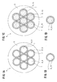
- a high frequency electric wire 6 of the present invention is provided in such a manner that a large number of wires 7 are bundled, twisted and insulated by an outer sheath S.
- the individual wire 7 has an extra-fine hollow pipe structure of a capillary shape.
- the individual wire 7 has a hollow section 8 with an extra-fine hollow pipe structure which is an air cavity 9 as shown in Figs. 1A and 1B , or the hollow section 8 of the individual wire 7 houses an insulating material 10 therein as shown in Figs. 1C and 1D .
- the individual wire 7 is provided to cause a metal conductor to adhere to the outer periphery of an extra-fine insulating yarn serving as the insulating material 10 by plating or vapor-deposition.
- the outer periphery of the individual wire 7 is coated with an insulating film 11 in both examples described above.
- the present invention is as outlined above.
- the wire 7 is made of a metal conductor such as pure copper, copper alloy, aluminum or gold.
- the typical diameter of the wire 7 is between several tens of microns and several hundreds of microns, but it is also possible for the wire 7 to have a diameter of several microns to several thousands of microns.
- the wire 7 is formed in an extra-fine linear shape and has a hollow pipe structure.
- the wire 7 is formed in a capillary tube shape of a micro unit of which the axial center section is a hollow section 8.
- the diameter of the hollow section 8 is 10 ⁇ and its peripheral thickness is 1.5 ⁇ .
- the wire 7 as shown in Figs. 1A and 1B is made according to a process for making an ordinary metal pipe.
- the wire 7 as shown in Figs. 1C and 1D is made by a metal plating method or a metal vapor-deposition method.
- a metal conductor is caused to adhere to an outer periphery of an extra-fine insulating yarn which has high insulating resistance and becomes an insulating material 10.
- the extra-fine insulating yarn with the line diameter of 10 ⁇ is coated with a metal conductor with the thickness of 1.5 ⁇ .
- res in ,_g las s, ceramics, rubber or other nonconductor is available for a material of the insulating yarn serving as the core material.
- polyphenyleneether PPE modified PPO
- Such an insulating yarn can be made by a single fiber or plurality of twisted fibers.
- the electric wire 6 is made by bundling and twisting a large number of wires 7 with an extra-fine hollow pipe structure of a capillary shape and then winding and insulating the wires 7 by an outer sheath S.
- the electric wire 6 is thus made by bundling and twisting a large number of wires 7 in accordance with the production of an ordinary electric wire. Namely, the wires 7 bundled in such a manner are twisted at predetermined pitch intervals and then, the entire periphery is insulated by an insulating film layer, that is, the outer sheath S to provide the electric wire 6.
- the wires 7 are individually bundled and twisted together to provide one electric wire 6.
- a large number of wires 7 can be bundled and twisted first to provide a child bundle and then, a plurality of child bundles can be bundles and twisted to provide one electric wire 6.
- a plurality of child bundles can be bundled and twisted to provide one parent bundle and then, a plurality of parent bundles can be bundled and twisted to provide one electric wire 6.
- an assembly of the parent bundles can be bundled and twisted to provide one electric wire 6.
- the hollow section 8 of the individual wire 7 is an air cavity 9 in which air exists. Also, in the electric wire 6 of an example as shown in Figs. 1C and 1D , the hollow section 8 of the wire 7 houses an insulating material 10 with high insulating resistance.
- the outer periphery of each wire 7 is coated with an insulating film 11.
- Anther structure of the electric wire 6 of this example conforms to the electric wire 6 and the individual wire 7 of an example shown in Figs. 1A and 1B .
- the outer periphery of each wire 7 is coated with an insulating film 11 and a hollow section 8 of each wire 7 houses an insulating material 10 with high insulating resistance.
- Another structure of the electric wire 6 of this example conforms to the electric wire 6 and the individual wire 7 of the example as shown in Figs. 1C and 1D .
- the insulating film 11 adapted to coat the outer periphery of the wire 7 conforms to the insulating film 4 of the electric wire 2 (litz wire) described above (refer to Figs. 4C and 4D ) and an enamel film is typically used, but it will be obvious that an insulating resin or other nonconductors can also be used.
- the electric wire 6 can be modified as follows.
- an outer periphery of the insulating film 11 is coated with a metal conductor with a structure conforming to the wire 7.
- the metal conductor can also be coated with a film with a structure conforming to the insulating film 11.
- Figs. 1A and 1C and Figs. 2A and 2C are schematic views, wherein 7 wires 7 are shown to provide one electric wire 6, but, for practical purposes, more than several tens of wires 7 to several tens of thousands of wires 7 are used to provide one electric wire 6.
- Non-contact power feeding device 12 (Non-contact power feeding device 12)
- a non-contact power feeding device 12 will be described hereunder with reference to Figs. 5 and 6 .
- a high frequency electric wire 6 according to the present invention is, for example, used in a non-contact power feeding device 12.
- the non-contact power feeding device 12 supplies power, with no contact, to a secondary coil 16 of a load side circuit 15 from a primary coil 14 of a power source side circuit 13 based on a mutual induction action of the electromagnetic induction.
- the electric wire 6 is used as a circuit cable 17 or coils 14, 16 and 18 in the power source side circuit 13 and the load side circuit 15 of the non-contact power feeding device 12 to fulfill its function for suppressing and reducing the increase in the alternating current resistance due to a high frequency alternating current, thereby reducing the Joule heat loss.
- a non-contact power feeding device 12 (IPS) will now be described in detail.
- the power source side circuit 13 on the power feeding side is fixedly secured to a ground side 19 in a power feeding area of a power feeding stand T and the like.
- the load side circuit 15 on the power receiving side is mounted on vehicles 20 such as an electric car or other movable bodies.
- the load side circuit 15 is typically connected to an in-vehicle battery 21, but there are some cases where it can be connected direct to various types of a load 22.
- the primary coil 14 of the power source side circuit 13 and the secondary side coil 16 of the load side circuit 15 are positioned to face each other with no contact through an air gap g in the case of power feeding.
- the secondary coil 16 is connected to the in-vehicle battery 21 in an example of Fig. 5 and a running motor 23 is driven by the battery 21.
- Reference numeral 24 in Fig. 5 is a converter for converting an alternating current to a direct current and reference numeral 25 is an inverter for converting the direct current to the alternating current.
- a high frequency alternating current of, for example, about 100 kHz from a high frequency power source 26 is supplied to the primary coil 14 of the power source side circuit 13 as an exciting current, a magnetic field is generated to form a magnetic flux, wherein a magnetic path of the magnetic flux is formed between the primary coil 14 and the secondary coil 16.
- the primary coil 14 is electromagnetically coupled to the secondary coil 16.
- the magnetic flux passes through the secondary coil 16 for linkage to generate an induced electromotive force on the secondary coil 16.
- Non-contact power feeding device 12 power is supplied to the load side circuit 15 from the power source side circuit 13 by the mutual induction action of the electromagnetic induction.
- Reference numerals 27, 28, 29 in Fig. 6 are capacitors which are used for resonance with the coils 14, 16 and 18.
- the non-contact power feeding device 12 is as described above.
- the high frequency electric wire 6 according to embodiments of the present invention is constructed as described above. The operations of the embodiments of present invention will now be described.
Abstract
Description
- The present invention relates to a high frequency electric wire, and more particularly to an electric wire which can be used as a wiring material, a winding material or the like for high frequency.
- For example, a high frequency alternating current method is adopted in a non-contact power feeding device, but the increase in frequency is remarkable in the frequencies used.
- In other words, in the non-contact power feeding device which supplies power through an air gap to a power receiving side coil mounted on an electric vehicle and the like from a fixed power feeding side coil based on the mutual induction action of the electromagnetic induction, the high frequency alternating current method is adopted from the viewpoint of the needs such as improvement of battery charging efficiency, a larger gap size, and a light and small coil. In view of these needs, the high frequency of about 20 kHz is now used, but it is projected to use a high frequency between 50 kHz and 100 kHz or above 100 kHz in the future.
- For example, even in audio equipment, game equipment, personal computers and various types of other electrical appliances other than the non-contact power feeding device, the needs for adoption of the high frequency alternating current method and the increase in useful frequency are remarkable.
- In such a non-contact power feeding device and other equipment, an
electric wire Fig. 4 has been typically used as a wiring material, a winding material or the like; for example, as a circuit cable or a coil. - The
electric wire 1 as shown inFig. 4A is an ordinary electric wire of this kind. Theelectric wire 1 is made by bundling and twisting a large number ofwires 3 made of a solid wire, and insulating the entire outside surface by an outer sheath S. Theelectric wire 2 as shown inFig. 4C is referred to as a litz wire. Theelectric wire 2 is made, as shown inFig. 4D , by bundling and twisting a large number ofwires 5 of which the outer periphery is coated with aninsulating film 4 such as enamel, and then insulating the entire outside surface by an outer sheath S. Theindividual wire 5 is made of fine wire of which the diameter is 200 µ or less. -
Figs. 4A and 4C are schematic views, wherein oneelectric wire wires electric wire wires - Such a non-contact power feeding device is disclosed in
patent document 1. Theelectric wire 2, that is, the litz wire is disclosed, for example, inpatent document 2. - Patent Document 1: Japanese Unexamined Patent Publication No.
2008-087733 - Patent Document 2: Japanese Unexamined Patent Publication No.
Hei 5-263377 - It has been pointed out that the conventional technology has the following problems.
- In the case where the electric wire 1 (ordinary electric wire) as shown in
Fig. 4A is used as a circuit cable for a high frequency alternating current or for the high frequency power transmission, there are problems in high frequency alternating current resistance due to a skin effect, Joule heat loss, and power loss. - In other words, when the electric wire 1 (ordinary wire) is used, the higher the frequency, the higher the influence of the skin effect and as a result, the frequency characteristics deteriorate, the high frequency alternating current resistance increases, the square of the Joule heat loss increases and as a result, the power loss becomes obvious.
- The skin effect will now be described. As is well known, the higher the frequency, the easier the alternating current flows on a surface side of the
electric wire 1 by a mutual action between a generating alternating magnetic flux and an electric current and the electric current density is concentrated on the surface side. As a result, the high frequency alternating current flows intensively on part of the total cross-sectional area of theelectric wire 1, that is, on an extremely-thin section of the surface side and the alternating current resistance value increases due to reduction of the current-carrying area. - As is well known, the electric wire 2 (litz wire) as shown in
Fig. 4C has been developed for high frequency to solve the problems of the electric wire 1 (ordinary electric wire) described above. - Namely, the
electric wire 2 is made by bundling, for example, thousands ofextra-fine wires 5, of which the diameter is 200 µ or less, coated with aninsulating film 4. With this structure, theelectric wire 2 is provided in such a manner that a surface area of eachwire 5, that is, a surface area of its outer peripheral surface, can be increased in total. In other words, theelectric wire 2 is provided to disperse, split and reduce the concentration of the electric current density due to the skin effect by increasing the number of the surfaces, that is, the outer peripheral surfaces of theindividual wire 5 as compared to theelectric wire 1 described above, thereby increasing the surface area accordingly. - However, even in the
electric wire 2, it has been further required to suppress and decrease the high frequency alternating current resistance, to lower the Joule heat loss, and to reduce the power loss in accordance with a higher level of the useful frequency. In this manner, it has been desired to improve the frequency characteristics of theelectric wire 2. - It has also been pointed out that the
electric wire 2 has a problem from a cost viewpoint. First, the high frequency alternating current flows only on the surface of eachwire 5 based on the skin effect and it does not flow in the center thereof. In this manner, it has been pointed out that the central side of the total cross-sectional area of eachwire 5 except for the extremely-thin surface side is a non-use area, that is, a wasteful area on which the electric current does not flow and exhibits greater loss capability in material costs (as in theelectric wire 1 described above). It has also been pointed out that the production costs become higher because the outer periphery of eachwire 5 must be coated with aninsulating film 4. - In view of these circumstances, a high frequency electric wire of the present invention was developed to solve the problems of the conventional technology of this kind.
- It is therefore an object of the present invention to provide a high frequency electric wire in which, first, the high frequency alternating current resistance can be reduced to decrease a Joule heat loss, thereby improving the frequency characteristics, and, second, the first point can be excellently realized in terms of cost performance.
- A technical means of the present invention for solving these problems is as follows as stated in the claims of patent.
- A high frequency electric wire according to the present invention is provided in such a manner that a plurality of wires are bundled, twisted and insulated by an outer sheath. The individual wire has a hollow pipe structure of a capillary shape. Each wire may have a hollow pipe structure of a capillary shape.
- The hollow pipe structure may be an extra-fine hollow pipe structure. In certain preferred embodiments, the external diameter of the hollow pipe structure is 200 microns (µ) or less.
- Preferably, the plurality of wires is a large number, for example at least 10 or at least 20.
- Further, as described in the following
aspects 2 through 6, the high frequency electric wire according to the present invention can be modified by adding technically limited elements. - In the high frequency electric wire according to
aspect 1, the individual wire is provided with a hollow section with a hollow pipe structure providing an air cavity. - In the high frequency electric wire according to
aspect - In the high frequency electric wire according to
aspect - In the high frequency electric wire according to
aspect 1, the individual wire has a hollow section with a pipe structure adapted to house an insulating material therein. - In the high frequency electric wire according to
aspect 5, the individual wire is provided to cause a metal conductor to adhere to the outer periphery of an insulating yarn (e.g. an extra-fine insulating yarn) serving as the insulating material by plating or vapor deposition. - In the high frequency electric wire according to
aspect - In the high frequency electric wire according to
aspect - Operation of certain preferred embodiments of the present invention will now be described hereunder.
- (1) A high frequency electric wire is made by bundling and twisting a large number of wires, each having an extra-fine hollow pipe structure.
- (2) The electric wire is used as a wiring material or a winding material.
- (3) A large number of wires, each having a hollow pipe structure, have an inner periphery, respectively. In other words, the electric wire has a large surface area in total per unit length including the outer peripheral surface and as a result, the concentration of electric current density due to the skin effect can be dispersed, mitigated and decreased.
- (4) Since the electric wire is provided to spread the current-carrying surface of the high frequency alternating current, the alternating current resistance and the Joule heat loss can be decreased. Thus, the electric wire provides superb frequency characteristics because it is possible to reduce the influence of the skin effect which increases as the frequency becomes higher.
- (5) The points described under
items - (6) There is no nonuse and wasteful conductor section in the electric wire because the high frequency alternating current flows through substantially all of the cross-sectional area of a wire conductor section with a hollow pipe structure. Thus, there is no wasteful section in the conductor material of the individual wire and as a result, both the conductor cost and weight can be drastically decreased.
- (7) Further, the individual wire can be readily made by following a process conforming to a process for making an ordinary metal pipe or a process for causing a metal conductor to adhere to an extra-fine insulating yarn by a metal plating method or a metal vapor-deposition method.
- (8) Still further, the electric wire according to one embodiment of the present invention in which a hollow section of the individual wire is an air cavity is especially excellent in decrease in weight. In addition, the electric wire according to another embodiment of the present invention in which the hollow section of the individual wire houses an insulating material therein is excellent in strength, elasticity, flexibility and the like.
- (9) In the electric wire according to a still further embodiment of the present invention in which the individual wire is coated with an insulating film, the outer peripheral surface of the individual wire which was lost by the contact of each wire without the insulating film as well as the surface area of item (3) becomes a current-carrying surface. As a result, dispersion, mitigation and decrease of the concentration of the electric current density due to the skin effect can be accelerated to provide superb frequency characteristics.
- (10) The high frequency electric wire of at least the preferred embodiments of the present invention produces the following effects.
- The electric wire of at least the preferred embodiments of the present invention is excellent in frequency characteristics. In other words, the high frequency alternating current resistance can be decreased to reduce the Joule heat loss.
- The high frequency electric wire adopts a large number of wires with an extra-fine hollow pipe structure of a capillary shape. The concentration of the electric current density due to the skin effect can be dispersed, mitigated and reduced by bundling and twisting the individual wires.
- In this manner, in the electric wire, the high frequency alternating current resistance can be further suppressed and decreased to improve the frequency characteristics as compared to the ordinary electric wire and the litz wire of the conventional technology of this kind. As a result, the Joule heat loss can be reduced to dramatically cut the power loss. For example, these effects can be achieved even in the case where the electric wire is used in a circuit cable or a coil of the non-contact power feeding device.
- The first effect can be significantly realized in terms of various costs. Namely, the high frequency electric wire adopts a large number of wires with a hollow pipe structure of a capillary shape into which the electric current flows.
- The ordinary electric wire and the litz wire of the conventional technology of this kind described above are provided on the central side of each wire with a nonuse section, that is, a wasteful section into which the electric current does not flow due to the skin effect. Since the electric wire of the present invention is not provided with such a nonuse section, the loss can be eliminated. In the case of the electric wire of the present invention, the material cost of the individual wire corresponding to its central portion which is a hollow section can be decreased. Further, the hollow section of the electric wire of the present invention can contribute to a decrease in weight to attain weight saving.
- Since the individual wire of the electric wire of the preferred embodiments of the present invention can be made following a process conforming to a process for making an ordinary metal pipe or a process of a metal plating method or a metal vapor-deposition method, the electric wire can be readily made as in the ordinary electric wire of the conventional technology of this kind. The production cost of the electric wire of the present invention can be reduced as compared to the conventional technology (litz wire) in which an insulating film must be formed for each wire.
- As described above, the present invention, at least in its preferred embodiments, has a great effect in that the problems of the conventional technology of this kind can be solved by the first and second effects described above.
- The above and other objects, features and advantages of the present invention will become more apparent from the following description when taken in conjunction with the accompanying drawings.
-
Fig. 1 is provided to describe a preferred embodiment for carrying out the present invention regarding a high frequency electric wire, whereinFig. 1A is a schematic cross-sectional view of a first embodiment,Fig. 1B is a cross-sectional view of the individual wire used therein,Fig. 1C is a schematic cross-sectional view of a second embodiment, andFig. 1D is a cross-sectional view of the individual wire used therein; -
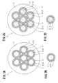
Fig. 2 is provided to describe a preferred embodiment for carrying out the present invention, whereinFig. 2A is a schematic cross-sectional view of a third embodiment,Fig. 2B is a cross-sectional view of the individual wire used therein,Fig. 2C is a schematic cross-sectional view of a fourth embodiment, andFig. 2D is a cross-sectional view of the individual wire used therein; -
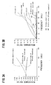
Fig. 3 provides graphs comparing the test results of the frequency characteristics of the embodiments of the present invention to those of the frequency characteristics of a conventional technology of this kind, whereinFig. 3A shows one example andFig. 3B shows another example; -
Fig. 4 is provided to describe a conventional technology of this kind, whereinFig. 4A is a schematic cross-sectional view of an ordinary electric wire,Fig. 4B is a cross-sectional view of the individual wire used therein,Fig. 4C is a schematic cross-sectional view of a litz wire, andFig. 4D is a cross-sectional view of the individual wire used therein; -
Fig. 5 is provided to describe a non-contact power feeding device, whereinFig. 5A is the explanatory side view andFig. 5B is a block diagram; and -
Fig. 6 is a circuit diagram to describe the non-contact power feeding device. - Preferred embodiments of the present invention will now be described in detail, by way of example only.
- An outline of the present invention, at least in its preferred embodiments, will be described with reference to
Fig. 1 and2 . - A high frequency
electric wire 6 of the present invention is provided in such a manner that a large number ofwires 7 are bundled, twisted and insulated by an outer sheath S. Theindividual wire 7 has an extra-fine hollow pipe structure of a capillary shape. - As a typical example, the
individual wire 7 has a hollow section 8 with an extra-fine hollow pipe structure which is an air cavity 9 as shown inFigs. 1A and 1B , or the hollow section 8 of theindividual wire 7 houses an insulating material 10 therein as shown inFigs. 1C and 1D . In the latter example, theindividual wire 7 is provided to cause a metal conductor to adhere to the outer periphery of an extra-fine insulating yarn serving as the insulating material 10 by plating or vapor-deposition. - As shown in
Fig. 2 , it can also be considered that the outer periphery of theindividual wire 7 is coated with an insulatingfilm 11 in both examples described above. - The present invention, at least in its preferred embodiments, is as outlined above.
- The present invention, at least in its preferred embodiments, will now be described in detail.
- First, the
individual wire 7 of theelectric wire 6 is described with reference toFig. 1 . Thewire 7 is made of a metal conductor such as pure copper, copper alloy, aluminum or gold. The typical diameter of thewire 7 is between several tens of microns and several hundreds of microns, but it is also possible for thewire 7 to have a diameter of several microns to several thousands of microns. - The
wire 7 is formed in an extra-fine linear shape and has a hollow pipe structure. In other words, thewire 7 is formed in a capillary tube shape of a micro unit of which the axial center section is a hollow section 8. To take an example, the diameter of the hollow section 8 is 10 µ and its peripheral thickness is 1.5 µ. - The
wire 7 as shown inFigs. 1A and 1B is made according to a process for making an ordinary metal pipe. In addition, thewire 7 as shown inFigs. 1C and 1D is made by a metal plating method or a metal vapor-deposition method. - In the metal plating method or the metal vapor-deposition method, a metal conductor is caused to adhere to an outer periphery of an extra-fine insulating yarn which has high insulating resistance and becomes an insulating material 10. For example; the extra-fine insulating yarn with the line diameter of 10 µ is coated with a metal conductor with the thickness of 1.5 µ.For example, resin,_glass, ceramics, rubber or other nonconductor is available for a material of the insulating yarn serving as the core material. In the case where high tensile force is required, as an example, polyphenyleneether PPE (modified PPO) (Trademark "Zylon" by General Electric Co., Ltd., USA) can be used. Such an insulating yarn can be made by a single fiber or plurality of twisted fibers.
- The
electric wire 6 is made by bundling and twisting a large number ofwires 7 with an extra-fine hollow pipe structure of a capillary shape and then winding and insulating thewires 7 by an outer sheath S. - First, several tens of
wires 7 to several tens of thousands ofwires 7 are bundled to provide oneelectric wire 6. For example, 2,000 to 8,000wires 7 are used to provide anelectric wire 6 of which the conductor's cross-sectional area is 1.25 sq.mm. About 50,000wires 7 are used to provide anelectric wire 6 of which the conductor's cross-sectional area is 11 sq.mm. - The
electric wire 6 is thus made by bundling and twisting a large number ofwires 7 in accordance with the production of an ordinary electric wire. Namely, thewires 7 bundled in such a manner are twisted at predetermined pitch intervals and then, the entire periphery is insulated by an insulating film layer, that is, the outer sheath S to provide theelectric wire 6. - Usually, the
wires 7 are individually bundled and twisted together to provide oneelectric wire 6. However, a large number ofwires 7 can be bundled and twisted first to provide a child bundle and then, a plurality of child bundles can be bundles and twisted to provide oneelectric wire 6. Further, a plurality of child bundles can be bundled and twisted to provide one parent bundle and then, a plurality of parent bundles can be bundled and twisted to provide oneelectric wire 6. Still further, an assembly of the parent bundles can be bundled and twisted to provide oneelectric wire 6. - In the
electric wire 6 of an example as shown inFigs. 1A and 1B , the hollow section 8 of theindividual wire 7 is an air cavity 9 in which air exists.
Also, in theelectric wire 6 of an example as shown inFigs. 1C and 1D , the hollow section 8 of thewire 7 houses an insulating material 10 with high insulating resistance. - Further, in the
electric wire 6 of an example as shown inFigs. 2A and 2B , the outer periphery of eachwire 7 is coated with an insulatingfilm 11. Anther structure of theelectric wire 6 of this example conforms to theelectric wire 6 and theindividual wire 7 of an example shown inFigs. 1A and 1B . Referring to theelectric wire 6 of an example as shown inFigs. 2C and 2D , the outer periphery of eachwire 7 is coated with an insulatingfilm 11 and a hollow section 8 of eachwire 7 houses an insulating material 10 with high insulating resistance. Another structure of theelectric wire 6 of this example conforms to theelectric wire 6 and theindividual wire 7 of the example as shown inFigs. 1C and 1D . - In two examples as shown in
Fig. 2 , the insulatingfilm 11 adapted to coat the outer periphery of thewire 7 conforms to the insulatingfilm 4 of the electric wire 2 (litz wire) described above (refer toFigs. 4C and 4D ) and an enamel film is typically used, but it will be obvious that an insulating resin or other nonconductors can also be used. - Although not shown in the figures, the
electric wire 6 can be modified as follows. For example, in the examples as shown inFigs. 2A and 2B and in the examples as shown inFigs. 2C and 2D , it can also be considered that an outer periphery of the insulatingfilm 11 is coated with a metal conductor with a structure conforming to thewire 7. Further, the metal conductor can also be coated with a film with a structure conforming to the insulatingfilm 11. -
Figs. 1A and 1C andFigs. 2A and 2C are schematic views, wherein 7wires 7 are shown to provide oneelectric wire 6, but, for practical purposes, more than several tens ofwires 7 to several tens of thousands ofwires 7 are used to provide oneelectric wire 6. - Details of the present invention, at least in its preferred embodiments, are as described above.
- A non-contact
power feeding device 12 will be described hereunder with reference toFigs. 5 and6 . - A high frequency
electric wire 6 according to the present invention is, for example, used in a non-contactpower feeding device 12. The non-contactpower feeding device 12 supplies power, with no contact, to asecondary coil 16 of aload side circuit 15 from aprimary coil 14 of a powersource side circuit 13 based on a mutual induction action of the electromagnetic induction. - The
electric wire 6 is used as acircuit cable 17 or coils 14, 16 and 18 in the powersource side circuit 13 and theload side circuit 15 of the non-contactpower feeding device 12 to fulfill its function for suppressing and reducing the increase in the alternating current resistance due to a high frequency alternating current, thereby reducing the Joule heat loss. - Such a non-contact power feeding device 12 (IPS) will now be described in detail. As shown in
Fig. 5 , the powersource side circuit 13 on the power feeding side is fixedly secured to aground side 19 in a power feeding area of a power feeding stand T and the like. - On the contrary, the
load side circuit 15 on the power receiving side is mounted onvehicles 20 such as an electric car or other movable bodies. Theload side circuit 15 is typically connected to an in-vehicle battery 21, but there are some cases where it can be connected direct to various types of aload 22. Theprimary coil 14 of the powersource side circuit 13 and thesecondary side coil 16 of theload side circuit 15 are positioned to face each other with no contact through an air gap g in the case of power feeding. - The
secondary coil 16 is connected to the in-vehicle battery 21 in an example ofFig. 5 and a runningmotor 23 is driven by thebattery 21.Reference numeral 24 inFig. 5 is a converter for converting an alternating current to a direct current andreference numeral 25 is an inverter for converting the direct current to the alternating current. - In the case of power feeding, when a high frequency alternating current of, for example, about 100 kHz from a high
frequency power source 26 is supplied to theprimary coil 14 of the powersource side circuit 13 as an exciting current, a magnetic field is generated to form a magnetic flux, wherein a magnetic path of the magnetic flux is formed between theprimary coil 14 and thesecondary coil 16. In this manner, theprimary coil 14 is electromagnetically coupled to thesecondary coil 16. The magnetic flux passes through thesecondary coil 16 for linkage to generate an induced electromotive force on thesecondary coil 16. - In the non-contact
power feeding device 12, power is supplied to theload side circuit 15 from the powersource side circuit 13 by the mutual induction action of the electromagnetic induction.Reference numerals Fig. 6 are capacitors which are used for resonance with thecoils - The non-contact
power feeding device 12 is as described above. - The high frequency
electric wire 6 according to embodiments of the present invention is constructed as described above. The operations of the embodiments of present invention will now be described. - (1) The high frequency
electric wire 6 of the present invention is made by bundling and twisting a large number ofwires 7 with an extra-fine hollow pipe structure of a capillary tube shape (refer toFigs. 1 and2 ). - (2) The
electric wires 6 is used as a high frequency wiring or winding material. Theelectric wire 6 is used, for example, as a circuit cable or coils 14, 16 and 18 (refer to the non-contactpower feeding device 12 ofFig. 6 ). Further, theelectric wire 6 is used for wiring of audio equipment, game equipment, personal computers and various types of other electric appliances, for example, for wiring for feeding acoustic frequency power to a speaker or an earphone. - (3) When the alternating current is sent to the
electric wire 6, the concentration of the electric current density by the skin effect can be dispersed, mitigated and decreased.
Namely, theelectric wire 6 is made by bundling and twisting a large number of wires 7 (e.g., several tens of wires to several tens of thousands of wires) with a hollow pipe structure. Eachwire 7 subdivided in this way has many inner peripheral surfaces corresponding to the number ofwires 7. As a result, theelectric wire 6 has also a larger surface area in total per unit length including its outer peripheral surface in proportion to the number of wires 7 (refer toFigs. 1 and2 ).
In theelectric wire 6, the electric current density of eachwire 7 can be lowered in response to such a larger surface area. Accordingly, the influence of the skin effect which increases as the frequency becomes high is dispersed, mitigated and decreased. In other words, the concentration of electric current density due to the skin effect is dispersed, mitigated and decreased as compared to the electric wire of which the outer diameter of the conductor and the number of wires are the same.
In the example ofFig. 2 , the outer peripheral surface of eachwire 7 is insulated and a disadvantage of the outer peripheral surface is eliminated, but the cost of the insulatingfilm 11 is increased. - (4) In this manner, in the
electric wire 6, the high frequency current also flows to a newly formed large inner peripheral surface and the concentration of the electric current density of the high frequency alternating current can be dispersed, mitigated and decreased. Simply, since the resistance is substantially in inverse proportion to the current-carrying area, the high frequency alternating current resistance is suppressed and decreased to reduce the Joule heat loss.
In this manner, theelectric wire 6 can reduce the influence of the skin effect which increases as the frequency become high, thereby providing excellent frequency characteristic. - (5) The operation of the present invention of item (4) described above has been backed up by the test results. In other words, an experiment has shown that the
electric wire 6 according to the present invention is excellent in frequency characteristics. The results of the experiment are shown in the graph ofFig. 3 .
In this experiment, the alternating current resistance value of theelectric wire 6 of the embodiments of the present invention and that of the conventional technology of this kind in 1 kHz of frequency are regarded as 1 and the ratio of the alternating current resistance value for each frequency was actually measured.
Referring to theelectric wire 6 of the present invention used in the experiment, the number of theindividual wires 7 used in a bundle for an electric wire B (the conductor cross-sectional area: 1.25 sq.mm) is 4 times the number ofwires 7 for an electric wire A (the conductor cross-sectional area: 1.25/4 sq.mm) (the number of electric wires A: 2,000; the number of the electric wires B; 8,000). Theelectric wire 6 of the example shown inFig. 1A was used for the electric wires A and B.
A commercially available twisted wire (the conductor cross-sectional area: 1.25 sq.mm) was used for the ordinary electric wire, that is, the electric wire 1 (refer toFig. 4A ). As for a litz wire A (the conductor cross-sectional area: 70 sq.mm) and a litz wire B (the conductor cross-sectional area: 11 sq.mm), that is, theelectric wire 2 described above (refer toFig. 4C ), the electric wire used in around 20 kHz of frequency was used. Further, as for an ordinary power cable (the conductor cross-sectional area: 14 sq.mm), a commercially available cable was used.
As a result of providing the high frequency alternating current to each electric wire under equal conditions, as shown inFigs. 3A and 3B (the vertical axis: resistance ratio; the horizontal axis: frequency), it was demonstrated that theelectric wire 6 of the present invention, that is, the electric wires A and B had excellent frequency characteristics as compared to the conventional technology of this kind. In the case of the electric wires A and B of the present invention, data has shown that even though the frequency becomes high, the increase in a resistance ratio is suppressed to maintain an extremely low resistance ratio and the resistance ratio is on a declining trend. It was also confirmed that there was little difference in the data for the electric wires A and B and these wires were the same in performance. In other words, the same frequency characteristics could be obtained.
Also, data has shown that, in the case of the ordinary electric wire, the litz wires A and B, and the ordinary power cable, the resistance ratio shows a sharp increase as the frequency becomes high. - (6) In the
electric wire 6 of the present invention provided with such an excellent frequency characteristic, theindividual wire 7 has a hollow pipe structure and the high frequency alternating current flows on the whole surface making the individual wire 7 a circular conductor.
On the contrary, in the case of the electric wire 1 (ordinary electric wire) and the electric wire 2 (litz wire) of the conventional technology of this kind, the current-carrying surface is only the outer peripheral surface thereof. In this manner, theindividual wires Figs. 1 ,2 and4 ).
In this manner, unlike the conventional technology of this kind, since theelectric wire 6 is not provided with a nonuse section, that is, a wasteful section to which the electric current does not flow and the waste, of the metal conductor which is the material for theindividual wire 7 can be greatly eliminated, both the weight and cost can be significantly decreased. - (7) Further, the
electric wire 6 can be readily made. Namely, theindividual wires 7 as shown inFigs. 1A and 1B are made according to a process for making ordinary metal pipe. Still further, theindividual wires 7 as shown in an example ofFigs. 1C and 1D are made by causing the conductor metal to adhere to the outer periphery of the extra-fine insulating yarn by a metal plating method or a metal vapor-deposition method. Accordingly, theelectric wire 6 can be readily made in the same way as the electric wire 1 (ordinary electric wire) described above. - (8) Incidentally, advantages of each example of the present invention will now be described. Since the hollow section of the
individual wire 7 is an air cavity 9, there is an advantage in that theelectric wire 6 of the example as shown inFig. 1A is particularly excellent in decrease in weight as described in item (6) described above. In addition, since theelectric wire 6 of the example as shown inFig. 1C is provided in such a manner that the hollow section 8 of theindividual wire 7 houses the insulating material 10 therein, there is an advantage in that theelectric wire 6 is excellent in strength, elasticity and flexibility. - (9) The
electric wires 6 of the example shown inFigs. 2A and 2C have advantages described in item (8) with reference to the correspondingFigs. 1A and 1C . Further, since the outer periphery of theindividual wire 7 is coated with the insulatingfilm 11, theelectric wire 6 of the example is particularly excellent in the frequency characteristics of item (4).
As described above, in theelectric wire 6 of the example as shown inFigs. 2A and 2C , the outer periphery of theindividual wire 7 is coated with the insulatingfilm 11. It is therefore possible to broaden the outer peripheral area of theindividual wire 7 as in the electric wire 2 (litz wire) of the conventional technology of this kind. In this manner, dispersion, mitigation and decrease of the concentration of the electric current density due to the skin effect can be further accelerated. -
- 1: Electric wire (Conventional example); 2: Electric wire (Conventional example); 3: Wire (Conventional example); 4: Insulating film (Conventional example); 5: Wire (Conventional example); 6: Electric Wire (Present invention); 7: Wire (Present invention); 8: Hollow section; 9: Air cavity; 10: Insulating material; 11: Insulating film; 12: Non-contact power feeding device; 13: Power source side circuit; 14: Primary coil; 15: Load side circuit; 16: Secondary coil; 17: Circuit cable; 18: Coil; 19: Ground side; 20: Vehicle; 21: Battery; 22: Load; 23: Motor; 24: Converter; 25: Inverter; 26: High Frequency power source; 27: Capacitor; 28: Capacitor; 29: Capacitor; g: Air gap; S: Outer sheath; T: Power feeding stand
Claims (8)
- A high frequency electric wire(6) in which a plurality of wires(7) are bundled, twisted and insulated by an outer sheath(S), characterized in that an individual wire(7) has a hollow pipe structure of a capillary shape.
- A high frequency electric wire(6) according to claim 1, wherein the hollow section(8) of the hollow pipe structure is an air cavity(9).
- A high frequency electric wire(6) according to claim 1 or 2, wherein the outer periphery of the individual wire(7) is coated with an insulating film(11).
- A high frequency electric wire(6) according to claim 1, 2 or 3, wherein the electric wire(6) is used in a non-contact power feeding device(12), the non-contact power feeding device(12) is provided to supply electric power to a secondary coil(16) of a load side circuit(15) from a primary coil(14) of a power source side circuit(13), with non contact, based on a mutual induction action of electromagnetic induction, and the electric wire(6) is used as a circuit cable(17) or a coil(14,16,18) of the non-contact power feeding device(12) to fulfill its function for suppressing or reducing an increase of the alternating current resistance due to a high frequency alternating current, thereby reducing the Joule heat loss.
- A high frequency electric wire(6) according to claim 1, wherein the individual wire(7) has a hollow section(8) with a hollow pipe structure adapted to house an insulating material(10) therein.
- A high frequency electric wire(6) according to claim 5, wherein the individual wire(7) is composed to cause a metal conductor to adhere to the outer periphery of an insulating yarn which serves as the insulating material(10) by plating or vapor-deposition.
- A high frequency electric wire(6) according to claim 5 or 6, wherein the outer periphery of the individual wire(7) is coated with an insulating film(11).
- A high frequency electric wire(6) according to claim 5, 6 or 7, wherein the electric wire(6) is used in a non-contact power feeding device(12), the non-contact power feeding device(12) is provided to supply electric power to a secondary coil(16) of a load side circuit(15) from a primary coil(14) of a power source side circuit(13) based on a mutual induction action of electromagnetic induction, and the electric wire(6) is used as a circuit cable (17) or a coil(14,16,18) of the non-contact power feeding device(12) to suppress or reduce the increase of the alternating current resistance due to a high frequency alternating current, thereby reducing the Joule heat loss.
Applications Claiming Priority (1)
| Application Number | Priority Date | Filing Date | Title |
|---|---|---|---|
| JP2009281587A JP2011124129A (en) | 2009-12-11 | 2009-12-11 | High-frequency electric wire |
Publications (2)
| Publication Number | Publication Date |
|---|---|
| EP2333788A2 true EP2333788A2 (en) | 2011-06-15 |
| EP2333788A3 EP2333788A3 (en) | 2012-06-20 |
Family
ID=42340520
Family Applications (1)
| Application Number | Title | Priority Date | Filing Date |
|---|---|---|---|
| EP10251041A Withdrawn EP2333788A3 (en) | 2009-12-11 | 2010-06-04 | High frequency electric wire |
Country Status (4)
| Country | Link |
|---|---|
| US (1) | US8299654B2 (en) |
| EP (1) | EP2333788A3 (en) |
| JP (1) | JP2011124129A (en) |
| CN (1) | CN102097169A (en) |
Cited By (1)
| Publication number | Priority date | Publication date | Assignee | Title |
|---|---|---|---|---|
| EP2525370A1 (en) * | 2011-05-16 | 2012-11-21 | AEG Power Solutions B.V. | High frequency energy cable |
Families Citing this family (21)
| Publication number | Priority date | Publication date | Assignee | Title |
|---|---|---|---|---|
| US20120293109A1 (en) * | 2011-05-19 | 2012-11-22 | Yariv Glazer | Method and System for Efficiently Exploiting Renewable Electrical Energy Sources |
| JP2013012637A (en) * | 2011-06-30 | 2013-01-17 | Yazaki Corp | Power supply system |
| US9583259B2 (en) | 2012-03-20 | 2017-02-28 | Qualcomm Incorporated | Wireless power transfer device and method of manufacture |
| US9160205B2 (en) | 2012-03-20 | 2015-10-13 | Qualcomm Incorporated | Magnetically permeable structures |
| US9653206B2 (en) * | 2012-03-20 | 2017-05-16 | Qualcomm Incorporated | Wireless power charging pad and method of construction |
| TWI537990B (en) * | 2012-05-25 | 2016-06-11 | Adv Flexible Circuits Co Ltd | A soft circuit cable with two or more groups of clusters |
| JP5792120B2 (en) * | 2012-05-31 | 2015-10-07 | タツタ電線株式会社 | High-frequency current wire |
| CN103545035B (en) * | 2012-07-09 | 2017-04-12 | 株式会社Kanzacc | Electric wire |
| JP6147600B2 (en) * | 2012-10-11 | 2017-06-14 | 株式会社Kanzacc | Litz wire |
| JP6169430B2 (en) * | 2013-07-22 | 2017-07-26 | 矢崎総業株式会社 | High frequency wire and method for manufacturing the same |
| JP6262500B2 (en) | 2013-11-18 | 2018-01-17 | トヨタ自動車株式会社 | Power receiving device |
| JP2016066915A (en) * | 2014-09-25 | 2016-04-28 | 横浜ゴム株式会社 | Antenna and manufacturing method of the same |
| CN104485168B (en) * | 2014-12-31 | 2017-01-18 | 江苏亨通线缆科技有限公司 | Low-skin-effect large-wire-diameter cable |
| CN104575832A (en) * | 2015-02-09 | 2015-04-29 | 湖南华菱线缆股份有限公司 | Ultra-light suspension umbilical cable |
| US9516422B2 (en) * | 2015-02-16 | 2016-12-06 | Hiroshi Ohara | Weaving method for a damper of a loudspeaker |
| FR3058581B1 (en) * | 2016-11-10 | 2019-12-20 | Bioserenity | TEXTILE DEVICE CAPABLE OF COOPERATING WITH AN ELECTRONIC DEVICE AND ASSOCIATED ELECTRONIC DEVICE |
| US20190244726A1 (en) * | 2018-02-02 | 2019-08-08 | Averatek Corporation | Maximizing surfaces and minimizing proximity effects for electric wires and cables |
| JP7094716B2 (en) * | 2018-02-19 | 2022-07-04 | キヤノンメディカルシステムズ株式会社 | Inclined magnetic field coil |
| US11837933B2 (en) * | 2019-12-31 | 2023-12-05 | Mavel Edt S.P.A | Process for making an electric conductor for a winding of an electric machine, electric conductor made with such process and electric machine comprising a winding made with such electric conductor |
| WO2023047481A1 (en) * | 2021-09-22 | 2023-03-30 | ファナック株式会社 | Air purge mechanism, robot, and air purge method |
| FR3130090B1 (en) * | 2021-12-07 | 2023-11-24 | Electricite De France | device and system for transferring electrical energy |
Citations (2)
| Publication number | Priority date | Publication date | Assignee | Title |
|---|---|---|---|---|
| JPH05263377A (en) | 1992-03-13 | 1993-10-12 | Nippon Telegr & Teleph Corp <Ntt> | Litz wire |
| JP2008087733A (en) | 2006-10-05 | 2008-04-17 | Showa Aircraft Ind Co Ltd | Noncontact power supply device |
Family Cites Families (11)
| Publication number | Priority date | Publication date | Assignee | Title |
|---|---|---|---|---|
| GB2258940A (en) * | 1991-08-17 | 1993-02-24 | Lin Lieh Chao | Electrical cable |
| DE4209928C1 (en) * | 1992-03-24 | 1992-12-24 | Felten & Guilleaume Energietechnik Ag, 5000 Koeln, De | |
| JPH0660732A (en) * | 1992-08-10 | 1994-03-04 | Riken Densen Kk | Manufacture of litz wire and manufacturing device thereof |
| CN2153123Y (en) * | 1993-02-12 | 1994-01-12 | 林烈超 | Wire without skin-effect |
| US6750399B1 (en) * | 1999-02-19 | 2004-06-15 | Nkt Cables Ultera A/S | Cable, a method of constructing a cable, and use of a cable |
| CN2370531Y (en) * | 1999-04-20 | 2000-03-22 | 王泮锁 | Electric power wire |
| GB2362026A (en) * | 2000-05-04 | 2001-11-07 | Mark William Goldney Baker | Laminar flow cable |
| CN1560879A (en) * | 2004-03-09 | 2005-01-05 | 罗志昭 | Hollow core cable |
| US7718897B2 (en) * | 2006-05-19 | 2010-05-18 | General Electric Company | Low AC loss superconductor for a superconducting magnet and method of making same |
| CN101083160A (en) * | 2006-06-01 | 2007-12-05 | 泛达公司 | Conductor with non-circular cross-section |
| JP5135736B2 (en) * | 2006-08-28 | 2013-02-06 | パナソニック株式会社 | High frequency feeder |
-
2009
- 2009-12-11 JP JP2009281587A patent/JP2011124129A/en active Pending
-
2010
- 2010-06-02 US US12/792,323 patent/US8299654B2/en not_active Expired - Fee Related
- 2010-06-04 EP EP10251041A patent/EP2333788A3/en not_active Withdrawn
- 2010-06-28 CN CN2010102162125A patent/CN102097169A/en active Pending
Patent Citations (2)
| Publication number | Priority date | Publication date | Assignee | Title |
|---|---|---|---|---|
| JPH05263377A (en) | 1992-03-13 | 1993-10-12 | Nippon Telegr & Teleph Corp <Ntt> | Litz wire |
| JP2008087733A (en) | 2006-10-05 | 2008-04-17 | Showa Aircraft Ind Co Ltd | Noncontact power supply device |
Cited By (2)
| Publication number | Priority date | Publication date | Assignee | Title |
|---|---|---|---|---|
| EP2525370A1 (en) * | 2011-05-16 | 2012-11-21 | AEG Power Solutions B.V. | High frequency energy cable |
| US20120292075A1 (en) * | 2011-05-16 | 2012-11-22 | Aeg Power Solutions B.V. | High-power high-frequency cable |
Also Published As
| Publication number | Publication date |
|---|---|
| US20110140539A1 (en) | 2011-06-16 |
| EP2333788A3 (en) | 2012-06-20 |
| CN102097169A (en) | 2011-06-15 |
| JP2011124129A (en) | 2011-06-23 |
| US8299654B2 (en) | 2012-10-30 |
Similar Documents
| Publication | Publication Date | Title |
|---|---|---|
| US8299654B2 (en) | High frequency electric wire | |
| US9425662B2 (en) | Electric wire, coil, device for designing electric wire, and electric motor | |
| JP5266340B2 (en) | High frequency electric wire and high frequency coil | |
| JP5229381B2 (en) | Motor lead and motor coil | |
| JP7373709B2 (en) | High frequency coil parts, coil parts for wireless power supply, wireless power supply device, and manufacturing method of frequency coil parts | |
| JP4557887B2 (en) | Covered wire and automotive wire harness | |
| US9159468B2 (en) | High-voltage electrical transmission cable | |
| CN203165496U (en) | High frequency electrical concentric type compound stranding litz wire | |
| JP2007305479A (en) | Electric cable | |
| WO2023103317A1 (en) | Electronic element and high-frequency winding thereof | |
| CN101901641B (en) | Optimized stranded wire | |
| JP2013251051A (en) | Cable | |
| CN212010410U (en) | High-temperature-resistant high-flexibility single-core cable | |
| JP5159269B2 (en) | Composite wires and coils | |
| CN207742972U (en) | A kind of tension corrosion resisting steel core aluminum stranded wire | |
| WO2016185724A1 (en) | Litz wire, litz wire coil, and method for manufacturing litz wire | |
| JP2017174968A (en) | Reactor for high frequency | |
| CN205582559U (en) | Electronic trackless equipment's anti reel cable that pulls in pit | |
| CN220121517U (en) | Tear-resistant high-strength high-voltage inverter wire harness | |
| CN217588450U (en) | Copper-aluminum alloy mixed conductor | |
| CN215527331U (en) | Non-magnetic steel core reinforced overhead conductor | |
| CN208256304U (en) | Electric railway copper-alloy stranded conductor | |
| CN208126884U (en) | A kind of high frequency cable convenient for coiling | |
| EP3714469B1 (en) | Silent conductors | |
| JP2022189122A (en) | Wire for high frequency power transmission |
Legal Events
| Date | Code | Title | Description |
|---|---|---|---|
| PUAI | Public reference made under article 153(3) epc to a published international application that has entered the european phase |
Free format text: ORIGINAL CODE: 0009012 |
|
| AK | Designated contracting states |
Kind code of ref document: A2 Designated state(s): AL AT BE BG CH CY CZ DE DK EE ES FI FR GB GR HR HU IE IS IT LI LT LU LV MC MK MT NL NO PL PT RO SE SI SK SM TR |
|
| AX | Request for extension of the european patent |
Extension state: BA ME RS |
|
| PUAL | Search report despatched |
Free format text: ORIGINAL CODE: 0009013 |
|
| AK | Designated contracting states |
Kind code of ref document: A3 Designated state(s): AL AT BE BG CH CY CZ DE DK EE ES FI FR GB GR HR HU IE IS IT LI LT LU LV MC MK MT NL NO PL PT RO SE SI SK SM TR |
|
| AX | Request for extension of the european patent |
Extension state: BA ME RS |
|
| RIC1 | Information provided on ipc code assigned before grant |
Ipc: H02J 5/00 20060101ALI20120516BHEP Ipc: H01B 7/30 20060101AFI20120516BHEP Ipc: H01B 9/00 20060101ALN20120516BHEP |
|
| STAA | Information on the status of an ep patent application or granted ep patent |
Free format text: STATUS: THE APPLICATION IS DEEMED TO BE WITHDRAWN |
|
| 18D | Application deemed to be withdrawn |
Effective date: 20121221 |