EP2333359A1 - Improved multi-chamber carabiner - Google Patents
Improved multi-chamber carabiner Download PDFInfo
- Publication number
- EP2333359A1 EP2333359A1 EP20100194557 EP10194557A EP2333359A1 EP 2333359 A1 EP2333359 A1 EP 2333359A1 EP 20100194557 EP20100194557 EP 20100194557 EP 10194557 A EP10194557 A EP 10194557A EP 2333359 A1 EP2333359 A1 EP 2333359A1
- Authority
- EP
- European Patent Office
- Prior art keywords
- gate
- primary
- frame
- region
- carabiner
- Prior art date
- Legal status (The legal status is an assumption and is not a legal conclusion. Google has not performed a legal analysis and makes no representation as to the accuracy of the status listed.)
- Withdrawn
Links
- 238000000034 method Methods 0.000 claims description 14
- 239000000463 material Substances 0.000 claims description 10
- 230000001419 dependent effect Effects 0.000 claims description 7
- 239000011435 rock Substances 0.000 claims description 5
- 230000002493 climbing effect Effects 0.000 claims description 3
- 230000007246 mechanism Effects 0.000 description 16
- 230000008878 coupling Effects 0.000 description 7
- 238000010168 coupling process Methods 0.000 description 7
- 238000005859 coupling reaction Methods 0.000 description 7
- 230000008901 benefit Effects 0.000 description 4
- 239000000203 mixture Substances 0.000 description 4
- 230000008569 process Effects 0.000 description 2
- 230000004044 response Effects 0.000 description 2
- 230000003319 supportive effect Effects 0.000 description 2
- 241001503987 Clematis vitalba Species 0.000 description 1
- 230000003213 activating effect Effects 0.000 description 1
- 230000009194 climbing Effects 0.000 description 1
- 230000007774 longterm Effects 0.000 description 1
- 238000004519 manufacturing process Methods 0.000 description 1
- 238000005259 measurement Methods 0.000 description 1
- 239000007769 metal material Substances 0.000 description 1
- 238000000926 separation method Methods 0.000 description 1
Images


Classifications
-
- F—MECHANICAL ENGINEERING; LIGHTING; HEATING; WEAPONS; BLASTING
- F16—ENGINEERING ELEMENTS AND UNITS; GENERAL MEASURES FOR PRODUCING AND MAINTAINING EFFECTIVE FUNCTIONING OF MACHINES OR INSTALLATIONS; THERMAL INSULATION IN GENERAL
- F16B—DEVICES FOR FASTENING OR SECURING CONSTRUCTIONAL ELEMENTS OR MACHINE PARTS TOGETHER, e.g. NAILS, BOLTS, CIRCLIPS, CLAMPS, CLIPS OR WEDGES; JOINTS OR JOINTING
- F16B45/00—Hooks; Eyes
- F16B45/02—Hooks with pivoting or elastically bending closing member
- F16B45/037—Multiple locking cavities, each having a pivoting closing member
-
- F—MECHANICAL ENGINEERING; LIGHTING; HEATING; WEAPONS; BLASTING
- F16—ENGINEERING ELEMENTS AND UNITS; GENERAL MEASURES FOR PRODUCING AND MAINTAINING EFFECTIVE FUNCTIONING OF MACHINES OR INSTALLATIONS; THERMAL INSULATION IN GENERAL
- F16B—DEVICES FOR FASTENING OR SECURING CONSTRUCTIONAL ELEMENTS OR MACHINE PARTS TOGETHER, e.g. NAILS, BOLTS, CIRCLIPS, CLAMPS, CLIPS OR WEDGES; JOINTS OR JOINTING
- F16B45/00—Hooks; Eyes
- F16B45/02—Hooks with pivoting or elastically bending closing member
- F16B45/023—Hooks with pivoting or elastically bending closing member the closing member pivoting about an axis perpendicular to the plane of the hook
-
- F—MECHANICAL ENGINEERING; LIGHTING; HEATING; WEAPONS; BLASTING
- F16—ENGINEERING ELEMENTS AND UNITS; GENERAL MEASURES FOR PRODUCING AND MAINTAINING EFFECTIVE FUNCTIONING OF MACHINES OR INSTALLATIONS; THERMAL INSULATION IN GENERAL
- F16B—DEVICES FOR FASTENING OR SECURING CONSTRUCTIONAL ELEMENTS OR MACHINE PARTS TOGETHER, e.g. NAILS, BOLTS, CIRCLIPS, CLAMPS, CLIPS OR WEDGES; JOINTS OR JOINTING
- F16B45/00—Hooks; Eyes
- F16B45/02—Hooks with pivoting or elastically bending closing member
- F16B45/027—Hooks with pivoting or elastically bending closing member and having position-locking means for the closing member
-
- Y—GENERAL TAGGING OF NEW TECHNOLOGICAL DEVELOPMENTS; GENERAL TAGGING OF CROSS-SECTIONAL TECHNOLOGIES SPANNING OVER SEVERAL SECTIONS OF THE IPC; TECHNICAL SUBJECTS COVERED BY FORMER USPC CROSS-REFERENCE ART COLLECTIONS [XRACs] AND DIGESTS
- Y10—TECHNICAL SUBJECTS COVERED BY FORMER USPC
- Y10S—TECHNICAL SUBJECTS COVERED BY FORMER USPC CROSS-REFERENCE ART COLLECTIONS [XRACs] AND DIGESTS
- Y10S24/00—Buckles, buttons, clasps
- Y10S24/30—Separable-fastener or required component thereof
- Y10S24/31—Separable-fastener or required component thereof with third, detached member completing interlock
- Y10S24/35—Third member includes relatively movable, separate components
Definitions
- the invention generally relates to mechanical coupling mechanisms such as carabiners and snap-hooks.
- the invention relates to an improved multi-chamber carabiner.
- Carabiners, snap-hooks, and releasable clamps are used in a variety of applications for releasably coupling objects to one another.
- a rock climber may use one or more carabiners to releasably secure a rope to a protection device during vertical ascension.
- Carabiners generally include a frame, a gate, and a releasable gate closure mechanism.
- the gate is configured to releasably engage the frame, so as to form a continuous inner region which can be used to mechanically couple to one or more objects.
- the releasable gate closure mechanism is configured to allow the gate to be selectively pivoted with respect to the frame to facilitate adding or removing items from the continuous inner region.
- the releasable gate closure mechanism simultaneously biases the gate toward a closed configuration with respect to the frame, so as to maintain mechanical coupling of items within the continuous inner region.
- a wide variety of frame, gate, and biasing systems exist to specifically accommodate particular applications and/or manufacturing costs for the carabiner.
- Various specialized carabiners are designed for particular applications.
- One type of specialized carabiner is configured for use between a belayer and a belay device during a roped rock climbing event.
- This particular type of carabiner is commonly referred to as a "belay carabiner" and may include one or more conventional features to optimize performance for belay purposes. These features include a respectively large enclosed region and a locking gate mechanism.
- the large enclosed region minimizes gate obstructions occurring as a result of coupling alternative types of belay devices to a harness.
- the locking mechanism locks the gate in a closed configuration to prevent inadvertent opening with respect to the frame.
- Various other specialized carabiner features may be included on a belay carabiner for particular benefits.
- conventional belay carabiners include multiple gates and multiple independent enclosed regions to enable specialized rope-friction functionality.
- conventional belay carabiners may include parallel enclosed regions with independent gates oriented outward for purposes of providing the user with an additional rappel rope friction generating system.
- Cross-loading occurs when a carabiner is loaded from a non-lengthwise orientation and/or rotates from a lengthwise parallel orientation to a lengthwise perpendicular orientation with respect to the harness of a user.
- the enclosed region of a carabiner has the highest tensile strength when the gate is in the closed configuration and the tensile forces are oriented along the longest axis.
- a carabiner may become rotationally misaligned during the course of a belay as a result of belay operation or carabiner rotation.
- the rotational misalignment of the carabiner may then expose the carabiner to a potential cross-loading scenario in which the carabiner is likely to receive non-lengthwise oriented tensile force.
- Various conventional carabiner designs have attempted to prevent the cross-loading scenario by restricting the rotational freedom of the belay carabiner once it is properly attached to the user.
- Unfortunately, conventional carabiner designs have been ineffective and/or inefficient by requiring complex multistep belay-configuration engagement/disengagement processes, poor durability, and/or awkward operation.
- the present invention relates to mechanical coupling mechanisms such as carabiners and snap-hooks.
- a multi-chamber carabiner configured for use as a belay carabiner, including a frame and a gate.
- the carabiner further includes a closed configuration in which the gate and frame form at least one enclosed region and an open configuration in which the gate is pivotably rotated within the at least one enclosed region to form a first opening.
- a gate biasing system is coupled to the frame and gate for purposes of mechanically biasing the gate toward the closed configuration with respect to the frame.
- the frame may include both a primary opening and a secondary opening, and the gate may include both a primary portion and a secondary portion.
- the primary portion of the gate may extend from the pivot location across the primary opening of the frame in the closed configuration, and the secondary portion may also extend from the pivot location across the secondary opening of the frame in the closed configuration.
- a second embodiment of the present invention may replace the secondary gate portion with a secondary gate that operates independently of the gate with respect to the frame.
- a third embodiment of the present invention relates to a method for engaging a carabiner with a harness for rock climbing activities including the acts of inserting the carabiner through both the primary and secondary openings.
- Embodiments of the present invention represent a significant advance in the field over conventional locking, multi-chamber, and belay type carabiners.
- Configuring the frame to include both a primary and secondary opening for purposes of separating the harness attachment point from the belay device attach point reliably prevents cross-loading during operation.
- the optional operational dependence between the primary and secondary gates or gate portions enables a user to efficiently translate the harness attachment point (i.e. belay loop) to the internal secondary enclosed region.
- the optional positioning/configuration of the secondary enclosed region and secondary opening within the enclosed region facilitates an improved engagement of the harness attachment point to the secondary enclosed region.
- the common pivot point of the primary and secondary gates/gate portions facilitates the use of the same gate biasing mechanism and/or an automatic operational dependence between the gates/gate portions.
- Figures 1A and 1B illustrate profile assembled views of a multi-chamber carabiner system with a gate in a closed and open configuration, respectively, in accordance with one embodiment of the present invention
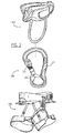
- Figure 2 illustrates an operational schematic of the multi-chamber carabiner system of Figure 1 with reference to a belay device and a harness in accordance with a method embodiment of the present invention
- Figure 3 illustrates a profile exploded view of the multi-chamber carabiner system of Figure 1 ;
- Figure 4 illustrates a perspective view of the multi-chamber carabiner system of Figure 1 ;
- Figure 5 illustrates a profile view of an alternative multi-chamber carabiner system
- Figures 6A-F illustrate operational perspective and profile views of alternative multi-chamber carabiner systems.
- the present invention relates to mechanical coupling mechanisms such as carabiners and snap-hooks.
- One embodiment of the present invention relates to a multi-chamber carabiner configured for use as a belay carabiner including a frame and a gate.
- the carabiner further includes a closed configuration in which the gate and frame form at least one enclosed region and an open configuration in which the gate is pivotably rotated within the at least one enclosed region to form a first opening.
- a gate biasing system is coupled to the frame and gate for purposes of mechanically biasing the gate toward the closed configuration with respect to the frame.
- the frame may include both a primary opening and a secondary opening and the gate may include both a primary portion and a secondary portion.
- the primary portion of the gate may extend from the pivot location across the primary opening of the frame in the closed configuration and the secondary portion may also extend from the pivot location across the secondary opening of the frame in the closed configuration.
- a second embodiment of the present invention may replace the secondary gate portion with a secondary gate that operates independently of the gate with respect to the frame.
- a third embodiment of the present invention relates to a method for engaging a carabiner with a harness for rock climbing activities including the acts of inserting the carabiner through both the primary and secondary openings. While embodiments of present invention are described in reference to a multi-chamber carabiner system, it will be appreciated that the teachings of present invention are applicable to other areas such as other types of carabiners and snap-hooks.
- Operably dependent/independent an operational dependence or independence between two components.
- Components which are operationally dependent are configured to automatically operate simultaneously. For example, when one lengthwise side of a teeter totter is lowered, the opposite side is automatically raised, meaning the two lengthwise sides are operationally dependent.
- Components which are operationally independent will not necessarily operate simultaneous to one another. For example, the keys on a piano may be played individually without activating the adjacent or remaining keys.
- Pivotably coupled - components which are coupled in a manner that facilitates a pivot type movement therebetween.
- a door is pivotably coupled to a door frame to facilitate pivotal rotation about the door frame.
- Enclosed region - a region which is geometrically contained within a perimeter.
- the enclosed region may be a two or three dimensionally enclosed region depending on the structure forming the perimeter. For example, all carabiners form some type of two dimensional enclosed region when the gate and frame are positioned in the closed configuration.
- the enclosed region is only two dimensional in that the enclosed region may be used to couple or attach components.
- Biasing - defaulting or urging a component toward a particular configuration For example, a rubber band is biased toward a particular circumference; this means that if it is stretched and released, it will return to the biased circumference.
- a second example may include a public restroom door that is biased toward a closed configuration; it may be opened, but upon release it automatically returns to the closed configuration.
- a third example may include an elevator that is biased towards the first floor of a building; the elevator may be engaged to transfer to a particular floor, but upon completion it will automatically return to the first floor.
- Carabiner - a mechanical device including a frame, a gate, and an inner region defined between the frame and gate.
- the gate is biased toward a closed configuration in which the inner region is continuous with regards to being enclosed by the frame and gate.
- the gate is configured to pivot with respect to the frame to create an opening of the inner region, thereby forming an open configuration.
- Gate biasing system a system of components configured to bias the gate of a carabiner toward a particular configuration.
- Gate locking system a system of components configured to lock or fix the gate of a carabiner in a closed configuration with respect to the frame.
- the system may include an engaged/locked state and a disengaged/released state.
- a gate locking system is selectively releasable in response to a particular force so as to disengage/release the gate locking system to enable the gate to function normally.
- the force required to disengage or engage the gate locking system is generally independent of that which is required to pivot the gate of a carabiner.
- a gate locking system may be biased towards an engaged or disengaged state.
- FIG. 1A, 1B , 3 , and 4 illustrate various views of a multi-chamber carabiner system, designated generally at 100.
- the system 100 includes a frame 110, a gate 120, a primary inner region 160, and a secondary inner region 170.
- the gate 120 is pivotably coupled to the frame about a pivot point 140.
- the frame 110 forms a substantial two dimensional enclosure of the primary and secondary inner regions 160, 170.
- Figure 1A illustrates the gate 120 and frame 110 in a closed configuration such that the primary and secondary inner regions 160, 170 are continuously enclosed within the gate 120 and frame 110.
- Figure 1B illustrates the gate 120 and frame 110 in an open configuration such that the gate 120 is pivoted about the pivot point 140 substantially within the primary inner region 160.
- a gate biasing system biases the gate 120 toward the closed configuration with respect to the frame 110.
- Various well known gate biasing systems may be used, including but not limited to those composed of springs, compliant materials, etc.
- the frame 110 forms the supportive structure of the system 100 and is shaped in a substantially concave manner with the respect to the gate 120. The exact curvature, shape, and composition of the frame 110 may be adjusted to modulate various other carabiner related performance aspects without affecting the teachings of the present invention.
- the frame 110 further includes a primary opening 165 and a secondary opening 175.
- the gate 120 also further includes a primary portion 130 and a secondary portion 150.
- the primary portion 130 of the gate 120 extends from the pivot point 140 across the primary opening 165 of the frame 110 in the closed configuration.
- the secondary portion 150 of the gate 120 extends from the pivot point 140 across the secondary opening 175 of the frame 110 in the closed configuration.
- the primary opening 165 extends between the nose 116 and pivot point 140 of the frame and is disposed across a perimeter region of the frame 110 such that it provides external access to the two dimensional primary enclosed region 160.
- the secondary opening 175 is located between a first and second point of concavity 112, 114 on the frame and is disposed across an interior region of the frame 110 such that it provides internal access to the separated secondary enclosed region 170 from the primary enclosed region 160. It will be appreciated that the exact shape of the frame 110 and gate 120 may be adjusted to adjust the size and performance characteristics of the openings 165, 175 and enclosed regions 160, 170. Although illustrated as a single component, it will be appreciated that alternative embodiments may include separate primary and secondary gate portions 130, 150 composed of independent materials.
- the secondary gate portion 150 may be composed of a plastic based material while the primary gate portion 130 is composed of a metal based material.
- the illustrated gate 120 further includes a notch 127, a pivot pin 123, a gate locking mechanism and a spring biasing system.
- the gate locking mechanism includes a female threaded region 125 on the primary gate portion 130, which is configured to selectively interface with a moveable sleeve 126 and O-ring 128.
- the moveable sleeve 126 includes a male threaded region on the interior and is oriented to translate in a lengthwise fashion along the primary gate portion 130.
- the gate locking mechanism includes an unlocked and locked configuration. The locked configuration corresponds to the gate locking mechanism impeding the gate 120 from pivoting with respect to the frame 110.
- the locked configuration also corresponds to the sleeve 126 being lengthwise positioned and/or translated away from the pivot point pin 123 along the threaded region 125 so as to at least partially extend over the notch 127.
- the unlocked configuration corresponds to the sleeve 126 being positioned and/or translated toward the pivot pin 123 along the threaded region 125 so as to not cover any portion of the notch 127.
- the spring biasing system includes a spring 124 and biasing member 122 coupled to the gate 120 to mechanically bias or urge the gate 120 toward the closed configuration.
- the spring biasing system simultaneously mechanically biases both the primary and secondary gate portions 150, 130 over the primary and secondary openings 165, 175 respectively.
- the spring 124 and biasing member 122 are disposed substantially within the gate 120 and frame 110 so as to prevent exposure to debris which may affect the mechanical bias force.
- the gate 120 may be pivoted about the pivot point 140 on the frame 110 to selectively switch from the closed to open configurations of the system 100.
- the primary gate portion 130 and the secondary gate portion 150 simultaneously pivot about the pivot point 140 so as to simultaneously expose/open both the primary opening 165 and the secondary opening 175. Therefore, the illustrated primary and secondary gate portions 130, 150 are operationally dependent.
- the operational dependence of the primary and secondary gate portions 130, 150 further means that a single user motion may be utilized to translate a coupling point (i.e. harness belay loop) within the secondary enclosed region 170 via the primary and secondary openings 165, 175.
- the primary and secondary gate portions may alternatively be operationally independent so as to operate independently.
- the primary and secondary gate portions still pivot about the common pivot point 140 but operate independently, requiring a user to manually pivot each gate portion in order to expose the respective opening. It will be appreciated that the common use of a single pivot point between the primary and secondary gate portions is a novel concept regardless of the operational independence or dependence of the primary and secondary gate portions.
- FIG. 2 illustrates an operational schematic of the multi-chamber carabiner system 100 with reference to a belay device 180 and a harness 190 in accordance with one method of operation.
- the illustrated schematic is designed to illustrate one common attachment scheme or utilization of one embodiment of the present invention. It will be appreciated that numerous specific attachment schemes and methods of operation may be utilized in accordance with embodiments of the present invention.
- the gate 120 is pivoted about the pivot location 140 of the frame 110 such that the primary portion is within a primary region of the at least one enclosed region and the secondary portion is within a secondary region of the at least one enclosed region; this state may also be referred to as the open configuration of the system 100.
- the harness 190 attachment point i.e.
- the harness belay loop is inserted through the primary opening and within the primary region of the at least one enclosed region of the system.
- the harness belay loop is further inserted or translated through the secondary opening and within the secondary region of the at least one enclosed region.
- the gate 120 is then allowed to automatically pivot about the pivot location 140 of the frame causing the primary portion to extend across the primary opening and the secondary portion to extend across the secondary opening; this state may also be referred to as the closed configuration of the system 100.
- This process thereby secures the harness 190 attachment point within the secondary region of the system.
- a user may optionally attach the belay device 180 to the system by again pivoting the 120 about the pivot location 140 of the frame 110 to engage the open configuration of the system 100.
- the belay device 180 attachment point i.e.
- a rope or safety line may also be coupled through the belay device 180 and coupled to the system 100 in accordance with standard belay techniques.
- the above described method therefore releasably attaches the belay device 180 and the harness 190 to the system 100 in separate enclosed regions.
- the separation of the primary and secondary enclosed regions within which the belay device 180 and the harness 190 are attached prevent cross-loading the system 100 during operation as described above.
- the above described method streamlines the necessary actions for routing the harness 190 and belay device 180 attachment points into separate regions of the multi-chamber system 100.
- FIG. 5 illustrates a profile view of an alternative multi-chamber carabiner system, designated generally at 200.
- the system 200 includes a frame 210, a gate 220, a primary inner region 260, and a secondary inner region 270.
- the gate 220 is pivotably coupled to the frame about a pivot point 240.
- the frame 210 forms a substantial two dimensional enclosure of the primary and secondary inner regions 260, 270.
- the gate 220 further includes a primary portion 530 and a secondary portion 250.
- the gate 220 and frame 210 are shown in a closed configuration such that the primary and secondary inner regions 260, 270 are continuously enclosed within the gate 220 and frame 210.
- the open configuration corresponds to the primary and secondary portions 230, 250 of the gate 220 pivoting about the pivot point 240 so as to expose the primary inner region 260 and the secondary inner region 270.
- the primary portion 230 is configured to pivot away from the primary inner region 260 while the secondary portion 250 is configured to simultaneously pivot within the secondary inner region 270 in the open configuration.
- the primary portion 230 and secondary portion 250 are operably dependent meaning that the two respective gate portions move simultaneously during operation (i.e. selectively engaging the open or closed configuration).
- a gate biasing system biases the gate 220 toward the closed configuration with respect to the frame 210.
- Various well known gate biasing systems may be used, including but not limited to those composed of springs, compliant materials, etc.
- the frame 510 forms the supportive structure of the system 200 and is shaped in a substantially concave manner with the respect to the gate 220.
- the exact curvature, shape, and composition of the frame 510 may be adjusted to modulate various other carabiner related performance aspects without affecting the teachings of the present invention.
- An analogous method of operation for the illustrated multi-chamber carabiner system 200 may include separately routing a harness attachment point within the secondary inner region 270 and a belay device attachment point within the primary inner region 260.
- Figures 6A-F illustrate operational perspective and profile views of alternative multi-chamber carabiner systems, respectively designated generally at 300, 400, 500, and 600.
- Figures 6A-6B illustrate an alternative multi-chamber carabiner system 300 in which the primary gate is in the closed configuration and the secondary gate is in the closed and open configurations, respectively.
- the system 300 includes separate primary and secondary gates that are operably independent of one another.
- the illustrated secondary gate of the system 300 pivots about an independent pivot location, is composed of an alternative material, and utilizes an independent biasing mechanism with respect to the primary gate.
- the illustrated secondary gate includes an open concave channel member configured to substantially conform to the frame in the open configuration ( Fig 6B).
- Figures 6C-6D illustrate another alternative multi-chamber carabiner system 400 in which the primary gate is in the closed configuration and the secondary gate is in the open and closed configurations, respectively.
- the system 400 also includes operationally independent primary and secondary gates which have independent pivot locations, alternative compositions, and separate biasing mechanisms.
- the secondary gate of the system 400 includes an enclosed concave channel member configured to substantially conform to the frame in the open configuration ( Fig 6C ).
- Figure 6E illustrates an alternative multi-chamber carabiner system 500 in which the primary gate is in the closed configuration and the secondary gate is in the closed configuration.
- the system 500 includes primary and secondary gates that are operationally dependent, have a common pivot location, are composed of a common material, but are configured to pivot in different orientations with respect to the frame.
- the system 500 includes primary and secondary inner regions that are rigidly separated by a portion of the frame, and therefore the only access to either the primary or secondary inner region is via the primary and secondary gate, respectively.
- Figure 6F illustrates an alternative multi-chamber carabiner system 600 in which the primary gate is in the closed configuration and the secondary gate is in the open configuration.
- the illustrated system 600 includes separate primary and secondary gates that are operationally independent of one another.
- the illustrated secondary gate of the system 600 pivots about an independent pivot location, is composed of an alternative material, and utilizes an independent biasing mechanism with respect to the primary gate.
- the illustrated frame is specifically shaped to include a constriction or taper at the division between the primary and secondary inner regions.
- the illustrated secondary gate includes a small tab-shaped member configured to substantially conform to the length of the constriction/taper so as to selectively separate the primary and secondary inner regions.
- multi-chamber carabiner systems may be practiced in accordance with the present invention, including one or more portions, combinations, and/or concepts of the embodiments illustrated in Figures 1-6 .
- a system may be practiced without a second inner region, with an alternative frame shape, with various material compositions, etc.
Landscapes
- Engineering & Computer Science (AREA)
- General Engineering & Computer Science (AREA)
- Mechanical Engineering (AREA)
- Hooks, Suction Cups, And Attachment By Adhesive Means (AREA)
- Emergency Lowering Means (AREA)
Abstract
One embodiment of the present invention relates to an automatically locking multi-chamber carabiner system including a frame (110), a gate (120), a gate biasing system (122,124), and a gate locking system (125,126). The frame and gate form a continuously enclosed inner region in a closed configuration with respect to the frame. When in an engaged state, the gate locking system is configured to automatically lock the gate in the closed configuration with respect to the frame. The gate comprising a first portion closing a primary opening of the frame and a second portion closing a secondary opening of the frame when in the closed position.

Description
- FIELD OF THE INVENTION
- The invention generally relates to mechanical coupling mechanisms such as carabiners and snap-hooks. In particular, the invention relates to an improved multi-chamber carabiner.
- BACKGROUND OF THE INVENTION
- Carabiners, snap-hooks, and releasable clamps are used in a variety of applications for releasably coupling objects to one another. For example, a rock climber may use one or more carabiners to releasably secure a rope to a protection device during vertical ascension. Carabiners generally include a frame, a gate, and a releasable gate closure mechanism. The gate is configured to releasably engage the frame, so as to form a continuous inner region which can be used to mechanically couple to one or more objects. The releasable gate closure mechanism is configured to allow the gate to be selectively pivoted with respect to the frame to facilitate adding or removing items from the continuous inner region. The releasable gate closure mechanism simultaneously biases the gate toward a closed configuration with respect to the frame, so as to maintain mechanical coupling of items within the continuous inner region. A wide variety of frame, gate, and biasing systems exist to specifically accommodate particular applications and/or manufacturing costs for the carabiner.
- Various specialized carabiners are designed for particular applications. One type of specialized carabiner is configured for use between a belayer and a belay device during a roped rock climbing event. This particular type of carabiner is commonly referred to as a "belay carabiner" and may include one or more conventional features to optimize performance for belay purposes. These features include a respectively large enclosed region and a locking gate mechanism. The large enclosed region minimizes gate obstructions occurring as a result of coupling alternative types of belay devices to a harness. The locking mechanism locks the gate in a closed configuration to prevent inadvertent opening with respect to the frame. Various other specialized carabiner features may be included on a belay carabiner for particular benefits. For example, conventional belay carabiners include multiple gates and multiple independent enclosed regions to enable specialized rope-friction functionality. For example, conventional belay carabiners may include parallel enclosed regions with independent gates oriented outward for purposes of providing the user with an additional rappel rope friction generating system.
- Various problems exist with conventional belay carabiners. One common dangerous scenario that may occur during use of a belay carabiner is referred to as "cross-loading". Cross-loading occurs when a carabiner is loaded from a non-lengthwise orientation and/or rotates from a lengthwise parallel orientation to a lengthwise perpendicular orientation with respect to the harness of a user. The enclosed region of a carabiner has the highest tensile strength when the gate is in the closed configuration and the tensile forces are oriented along the longest axis. A carabiner may become rotationally misaligned during the course of a belay as a result of belay operation or carabiner rotation. The rotational misalignment of the carabiner may then expose the carabiner to a potential cross-loading scenario in which the carabiner is likely to receive non-lengthwise oriented tensile force. Various conventional carabiner designs have attempted to prevent the cross-loading scenario by restricting the rotational freedom of the belay carabiner once it is properly attached to the user. Unfortunately, conventional carabiner designs have been ineffective and/or inefficient by requiring complex multistep belay-configuration engagement/disengagement processes, poor durability, and/or awkward operation.
- Therefore, there is a need in the industry for a carabiner design that minimizes cross-loading belay scenarios, provides long term durability, and overcomes the limitations of existing systems in a cost efficient manner.
- SUMMARY OF THE INVENTION
- The present invention relates to mechanical coupling mechanisms such as carabiners and snap-hooks. One embodiment of the present invention relates to a multi-chamber carabiner configured for use as a belay carabiner, including a frame and a gate. The carabiner further includes a closed configuration in which the gate and frame form at least one enclosed region and an open configuration in which the gate is pivotably rotated within the at least one enclosed region to form a first opening. A gate biasing system is coupled to the frame and gate for purposes of mechanically biasing the gate toward the closed configuration with respect to the frame. The frame may include both a primary opening and a secondary opening, and the gate may include both a primary portion and a secondary portion. The primary portion of the gate may extend from the pivot location across the primary opening of the frame in the closed configuration, and the secondary portion may also extend from the pivot location across the secondary opening of the frame in the closed configuration. A second embodiment of the present invention may replace the secondary gate portion with a secondary gate that operates independently of the gate with respect to the frame. A third embodiment of the present invention relates to a method for engaging a carabiner with a harness for rock climbing activities including the acts of inserting the carabiner through both the primary and secondary openings.
- Embodiments of the present invention represent a significant advance in the field over conventional locking, multi-chamber, and belay type carabiners. Configuring the frame to include both a primary and secondary opening for purposes of separating the harness attachment point from the belay device attach point reliably prevents cross-loading during operation. The optional operational dependence between the primary and secondary gates or gate portions enables a user to efficiently translate the harness attachment point (i.e. belay loop) to the internal secondary enclosed region. Likewise, the optional positioning/configuration of the secondary enclosed region and secondary opening within the enclosed region facilitates an improved engagement of the harness attachment point to the secondary enclosed region. In addition, the common pivot point of the primary and secondary gates/gate portions facilitates the use of the same gate biasing mechanism and/or an automatic operational dependence between the gates/gate portions.
- These and other features and advantages of the present invention will be set forth or will become more fully apparent in the description that follows and in the appended claims. The features and advantages may be realized and obtained by means of the instruments and combinations particularly pointed out in the appended claims. Furthermore, the features and advantages of the invention may be learned by the practice of the invention or will be obvious from the description, as set forth hereinafter.
- BRIEF DESCRIPTION OF THE DRAWINGS
- The following description of the invention can be understood in light of the Figures, which illustrate specific aspects of the invention and are a part of the specification. Together with the following description, the Figures demonstrate and explain the principles of the invention. The Figures presented in conjunction with this description are views of only particular-rather than complete-portions of the systems and methods of making and using the system according to the invention. In the Figures, the physical dimensions may be exaggerated for clarity.
-
Figures 1A and 1B illustrate profile assembled views of a multi-chamber carabiner system with a gate in a closed and open configuration, respectively, in accordance with one embodiment of the present invention; -
Figure 2 illustrates an operational schematic of the multi-chamber carabiner system ofFigure 1 with reference to a belay device and a harness in accordance with a method embodiment of the present invention; -
Figure 3 illustrates a profile exploded view of the multi-chamber carabiner system ofFigure 1 ; -
Figure 4 illustrates a perspective view of the multi-chamber carabiner system ofFigure 1 ; -
Figure 5 illustrates a profile view of an alternative multi-chamber carabiner system; and -
Figures 6A-F illustrate operational perspective and profile views of alternative multi-chamber carabiner systems. - DETAILED DESCRIPTION OF THE INVENTION The present invention relates to mechanical coupling mechanisms such as carabiners and snap-hooks. One embodiment of the present invention relates to a multi-chamber carabiner configured for use as a belay carabiner including a frame and a gate. The carabiner further includes a closed configuration in which the gate and frame form at least one enclosed region and an open configuration in which the gate is pivotably rotated within the at least one enclosed region to form a first opening. A gate biasing system is coupled to the frame and gate for purposes of mechanically biasing the gate toward the closed configuration with respect to the frame. The frame may include both a primary opening and a secondary opening and the gate may include both a primary portion and a secondary portion. The primary portion of the gate may extend from the pivot location across the primary opening of the frame in the closed configuration and the secondary portion may also extend from the pivot location across the secondary opening of the frame in the closed configuration. A second embodiment of the present invention may replace the secondary gate portion with a secondary gate that operates independently of the gate with respect to the frame. A third embodiment of the present invention relates to a method for engaging a carabiner with a harness for rock climbing activities including the acts of inserting the carabiner through both the primary and secondary openings. While embodiments of present invention are described in reference to a multi-chamber carabiner system, it will be appreciated that the teachings of present invention are applicable to other areas such as other types of carabiners and snap-hooks.
- The following terms are defined as follows:
- Operably dependent/independent - an operational dependence or independence between two components. Components which are operationally dependent are configured to automatically operate simultaneously. For example, when one lengthwise side of a teeter totter is lowered, the opposite side is automatically raised, meaning the two lengthwise sides are operationally dependent. Components which are operationally independent will not necessarily operate simultaneous to one another. For example, the keys on a piano may be played individually without activating the adjacent or remaining keys.
- Pivotably coupled - components which are coupled in a manner that facilitates a pivot type movement therebetween. For example, a door is pivotably coupled to a door frame to facilitate pivotal rotation about the door frame.
- Enclosed region - a region which is geometrically contained within a perimeter. The enclosed region may be a two or three dimensionally enclosed region depending on the structure forming the perimeter. For example, all carabiners form some type of two dimensional enclosed region when the gate and frame are positioned in the closed configuration. The enclosed region is only two dimensional in that the enclosed region may be used to couple or attach components.
- Biasing - defaulting or urging a component toward a particular configuration. For example, a rubber band is biased toward a particular circumference; this means that if it is stretched and released, it will return to the biased circumference. A second example may include a public restroom door that is biased toward a closed configuration; it may be opened, but upon release it automatically returns to the closed configuration. A third example may include an elevator that is biased towards the first floor of a building; the elevator may be engaged to transfer to a particular floor, but upon completion it will automatically return to the first floor.
- Carabiner - a mechanical device including a frame, a gate, and an inner region defined between the frame and gate. The gate is biased toward a closed configuration in which the inner region is continuous with regards to being enclosed by the frame and gate. In response to a particular force, the gate is configured to pivot with respect to the frame to create an opening of the inner region, thereby forming an open configuration.
- Gate biasing system - a system of components configured to bias the gate of a carabiner toward a particular configuration.
- Gate locking system - a system of components configured to lock or fix the gate of a carabiner in a closed configuration with respect to the frame. The system may include an engaged/locked state and a disengaged/released state. A gate locking system is selectively releasable in response to a particular force so as to disengage/release the gate locking system to enable the gate to function normally. The force required to disengage or engage the gate locking system is generally independent of that which is required to pivot the gate of a carabiner. A gate locking system may be biased towards an engaged or disengaged state.
- Lengthwise - an orientation for measurement referring to the longest dimension of a mechanical component.
- Reference is made to
Figures 1A, 1B ,3 , and4 which illustrate various views of a multi-chamber carabiner system, designated generally at 100. Thesystem 100 includes aframe 110, agate 120, a primaryinner region 160, and a secondaryinner region 170. Thegate 120 is pivotably coupled to the frame about apivot point 140. Theframe 110 forms a substantial two dimensional enclosure of the primary and secondaryinner regions Figure 1A illustrates thegate 120 andframe 110 in a closed configuration such that the primary and secondaryinner regions gate 120 andframe 110.Figure 1B illustrates thegate 120 andframe 110 in an open configuration such that thegate 120 is pivoted about thepivot point 140 substantially within the primaryinner region 160. A gate biasing system (not designated) biases thegate 120 toward the closed configuration with respect to theframe 110. Various well known gate biasing systems may be used, including but not limited to those composed of springs, compliant materials, etc. Theframe 110 forms the supportive structure of thesystem 100 and is shaped in a substantially concave manner with the respect to thegate 120. The exact curvature, shape, and composition of theframe 110 may be adjusted to modulate various other carabiner related performance aspects without affecting the teachings of the present invention. - The
frame 110 further includes aprimary opening 165 and asecondary opening 175. Thegate 120 also further includes aprimary portion 130 and asecondary portion 150. Theprimary portion 130 of thegate 120 extends from thepivot point 140 across theprimary opening 165 of theframe 110 in the closed configuration. Likewise, thesecondary portion 150 of thegate 120 extends from thepivot point 140 across thesecondary opening 175 of theframe 110 in the closed configuration. Theprimary opening 165 extends between thenose 116 andpivot point 140 of the frame and is disposed across a perimeter region of theframe 110 such that it provides external access to the two dimensional primaryenclosed region 160. Thesecondary opening 175 is located between a first and second point ofconcavity frame 110 such that it provides internal access to the separated secondaryenclosed region 170 from the primaryenclosed region 160. It will be appreciated that the exact shape of theframe 110 andgate 120 may be adjusted to adjust the size and performance characteristics of theopenings enclosed regions secondary gate portions secondary gate portion 150 may be composed of a plastic based material while theprimary gate portion 130 is composed of a metal based material. Some of the alternative embodiments are described and illustrated with reference toFigures 5-6 . - With specific reference to
Figure 3 , the illustratedgate 120 further includes anotch 127, apivot pin 123, a gate locking mechanism and a spring biasing system. The gate locking mechanism includes a female threaded region 125 on theprimary gate portion 130, which is configured to selectively interface with amoveable sleeve 126 and O-ring 128. Themoveable sleeve 126 includes a male threaded region on the interior and is oriented to translate in a lengthwise fashion along theprimary gate portion 130. The gate locking mechanism includes an unlocked and locked configuration. The locked configuration corresponds to the gate locking mechanism impeding thegate 120 from pivoting with respect to theframe 110. The locked configuration also corresponds to thesleeve 126 being lengthwise positioned and/or translated away from thepivot point pin 123 along the threaded region 125 so as to at least partially extend over thenotch 127. The unlocked configuration corresponds to thesleeve 126 being positioned and/or translated toward thepivot pin 123 along the threaded region 125 so as to not cover any portion of thenotch 127. The spring biasing system includes aspring 124 and biasingmember 122 coupled to thegate 120 to mechanically bias or urge thegate 120 toward the closed configuration. The spring biasing system simultaneously mechanically biases both the primary andsecondary gate portions secondary openings spring 124 and biasingmember 122 are disposed substantially within thegate 120 andframe 110 so as to prevent exposure to debris which may affect the mechanical bias force. - In operation, the
gate 120 may be pivoted about thepivot point 140 on theframe 110 to selectively switch from the closed to open configurations of thesystem 100. Theprimary gate portion 130 and thesecondary gate portion 150 simultaneously pivot about thepivot point 140 so as to simultaneously expose/open both theprimary opening 165 and thesecondary opening 175. Therefore, the illustrated primary andsecondary gate portions secondary gate portions enclosed region 170 via the primary andsecondary openings common pivot point 140 but operate independently, requiring a user to manually pivot each gate portion in order to expose the respective opening. It will be appreciated that the common use of a single pivot point between the primary and secondary gate portions is a novel concept regardless of the operational independence or dependence of the primary and secondary gate portions. - Reference is next made to
Figure 2 , which illustrates an operational schematic of themulti-chamber carabiner system 100 with reference to abelay device 180 and aharness 190 in accordance with one method of operation. The illustrated schematic is designed to illustrate one common attachment scheme or utilization of one embodiment of the present invention. It will be appreciated that numerous specific attachment schemes and methods of operation may be utilized in accordance with embodiments of the present invention. To attach theharness 190 to thesystem 100, thegate 120 is pivoted about thepivot location 140 of theframe 110 such that the primary portion is within a primary region of the at least one enclosed region and the secondary portion is within a secondary region of the at least one enclosed region; this state may also be referred to as the open configuration of thesystem 100. Theharness 190 attachment point (i.e. belay loop) is inserted through the primary opening and within the primary region of the at least one enclosed region of the system. The harness belay loop is further inserted or translated through the secondary opening and within the secondary region of the at least one enclosed region. Thegate 120 is then allowed to automatically pivot about thepivot location 140 of the frame causing the primary portion to extend across the primary opening and the secondary portion to extend across the secondary opening; this state may also be referred to as the closed configuration of thesystem 100. This process thereby secures theharness 190 attachment point within the secondary region of the system. A user may optionally attach thebelay device 180 to the system by again pivoting the 120 about thepivot location 140 of theframe 110 to engage the open configuration of thesystem 100. Thebelay device 180 attachment point (i.e. cable) is inserted through the primary opening and within the primary region of thesystem 100. Thegate 120 is then allowed to automatically pivot about thepivot location 140 of theframe 110 to the closed configuration of thesystem 100. It will be appreciated that a rope or safety line may also be coupled through thebelay device 180 and coupled to thesystem 100 in accordance with standard belay techniques. The above described method therefore releasably attaches thebelay device 180 and theharness 190 to thesystem 100 in separate enclosed regions. As a result, the separation of the primary and secondary enclosed regions within which thebelay device 180 and theharness 190 are attached prevent cross-loading thesystem 100 during operation as described above. In addition, the above described method streamlines the necessary actions for routing theharness 190 andbelay device 180 attachment points into separate regions of themulti-chamber system 100. - Reference is next made to
Figure 5 , which illustrates a profile view of an alternative multi-chamber carabiner system, designated generally at 200. Thesystem 200 includes aframe 210, agate 220, a primaryinner region 260, and a secondaryinner region 270. Thegate 220 is pivotably coupled to the frame about apivot point 240. Theframe 210 forms a substantial two dimensional enclosure of the primary and secondaryinner regions gate 220 further includes a primary portion 530 and asecondary portion 250. Thegate 220 andframe 210 are shown in a closed configuration such that the primary and secondaryinner regions gate 220 andframe 210. The open configuration (not shown) corresponds to the primary andsecondary portions gate 220 pivoting about thepivot point 240 so as to expose the primaryinner region 260 and the secondaryinner region 270. In this embodiment, theprimary portion 230 is configured to pivot away from the primaryinner region 260 while thesecondary portion 250 is configured to simultaneously pivot within the secondaryinner region 270 in the open configuration. In this embodiment, theprimary portion 230 andsecondary portion 250 are operably dependent meaning that the two respective gate portions move simultaneously during operation (i.e. selectively engaging the open or closed configuration). A gate biasing system (not designated) biases thegate 220 toward the closed configuration with respect to theframe 210. Various well known gate biasing systems may be used, including but not limited to those composed of springs, compliant materials, etc. The frame 510 forms the supportive structure of thesystem 200 and is shaped in a substantially concave manner with the respect to thegate 220. The exact curvature, shape, and composition of the frame 510 may be adjusted to modulate various other carabiner related performance aspects without affecting the teachings of the present invention. An analogous method of operation for the illustratedmulti-chamber carabiner system 200 may include separately routing a harness attachment point within the secondaryinner region 270 and a belay device attachment point within the primaryinner region 260. - Reference is next made to
Figures 6A-F , which illustrate operational perspective and profile views of alternative multi-chamber carabiner systems, respectively designated generally at 300, 400, 500, and 600.Figures 6A-6B illustrate an alternativemulti-chamber carabiner system 300 in which the primary gate is in the closed configuration and the secondary gate is in the closed and open configurations, respectively. Thesystem 300 includes separate primary and secondary gates that are operably independent of one another. In particular, the illustrated secondary gate of thesystem 300 pivots about an independent pivot location, is composed of an alternative material, and utilizes an independent biasing mechanism with respect to the primary gate. The illustrated secondary gate includes an open concave channel member configured to substantially conform to the frame in the open configuration (Fig 6B). Figures 6C-6D illustrate another alternativemulti-chamber carabiner system 400 in which the primary gate is in the closed configuration and the secondary gate is in the open and closed configurations, respectively. Thesystem 400 also includes operationally independent primary and secondary gates which have independent pivot locations, alternative compositions, and separate biasing mechanisms. The secondary gate of thesystem 400 includes an enclosed concave channel member configured to substantially conform to the frame in the open configuration (Fig 6C ).Figure 6E illustrates an alternativemulti-chamber carabiner system 500 in which the primary gate is in the closed configuration and the secondary gate is in the closed configuration. Thesystem 500 includes primary and secondary gates that are operationally dependent, have a common pivot location, are composed of a common material, but are configured to pivot in different orientations with respect to the frame. In addition, thesystem 500 includes primary and secondary inner regions that are rigidly separated by a portion of the frame, and therefore the only access to either the primary or secondary inner region is via the primary and secondary gate, respectively.Figure 6F illustrates an alternativemulti-chamber carabiner system 600 in which the primary gate is in the closed configuration and the secondary gate is in the open configuration. The illustratedsystem 600 includes separate primary and secondary gates that are operationally independent of one another. In particular, the illustrated secondary gate of thesystem 600 pivots about an independent pivot location, is composed of an alternative material, and utilizes an independent biasing mechanism with respect to the primary gate. The illustrated frame is specifically shaped to include a constriction or taper at the division between the primary and secondary inner regions. The illustrated secondary gate includes a small tab-shaped member configured to substantially conform to the length of the constriction/taper so as to selectively separate the primary and secondary inner regions. - It should be noted that various other multi-chamber carabiner systems may be practiced in accordance with the present invention, including one or more portions, combinations, and/or concepts of the embodiments illustrated in
Figures 1-6 . For example, a system may be practiced without a second inner region, with an alternative frame shape, with various material compositions, etc. - Various other embodiments have been contemplated, including combinations in whole or in part of the embodiments described above.
Claims (20)
- A multi-chamber carabiner configured for use as a belay carabiner comprising:a frame;a gate pivotably coupled about a pivot location to the frame;a closed configuration in which the gate and frame form at least one enclosed region;an open configuration in which the gate is pivotably rotated within the at least one enclosed region to form a first opening;a gate biasing system coupled to the frame and gate, biasing the gate toward the closed configuration with respect to the frame; andwherein the frame includes a primary opening and a secondary opening, and wherein the gate includes a primary portion and a secondary portion, and wherein the primary portion of the gate extends from the pivot location across the primary opening of the frame in the closed configuration, and wherein the secondary portion extends from the pivot location across the secondary opening of the frame in the closed configuration.
- The carabiner of claim 1, wherein the primary opening and secondary opening are independent of one another.
- The carabiner of claim 1, wherein the primary opening is on a perimeter region of the at least one enclosed region.
- The carabiner of claim 1, wherein the secondary opening is within the at least one enclosed region.
- The carabiner of claim 1, wherein the enclosed region includes two interior points of concavity across which the secondary opening extends.
- The carabiner of claim 1, wherein the primary and secondary portions of the gate are operably dependent so as to simultaneously pivot about the pivot location in the open configuration.
- The carabiner of claim 1, wherein the primary and secondary portions of the gate are lengthwise coupled at the pivot location.
- The carabiner of claim 1, wherein the primary and secondary gate portions are composed of substantially different materials.
- The carabiner in claim 1, wherein the at least one enclosed region is a single region that includes a primary region and a secondary region, and wherein the secondary opening is between the primary and secondary regions of the at least one enclosed region, and wherein the primary region is larger than the secondary region.
- The carabiner of claim 1, wherein the at least one enclosed region includes a separate primary and secondary enclosed region, and wherein the primary opening is disposed on the primary enclosed region and the secondary opening is disposed on the secondary enclosed region.
- The carabiner of claim 1, wherein the primary gate portion includes a gate locking system configured to include an engaged state and a disengaged state, and wherein the engaged state corresponds to the gate and frame being locked in the closed configuration, and wherein the disengaged state corresponds to the gate being pivotably rotatable with respect to frame.
- A multi-chamber carabiner configured for use as a belay carabiner comprising:a frame;a gate pivotably coupled to the frame about a pivot location;a closed configuration in which the gate extends from the pivot location across a primary opening of the frame to form at least one enclosed region;an open configuration in which the gate is pivotably rotated within the at least one enclosed region to form a first opening;a gate biasing system coupled to the frame and gate, biasing the gate toward the closed configuration with respect to the frame; anda secondary gate pivotably coupled to the frame about the pivot location, wherein the at least one enclosed region includes a primary region and a secondary region, and wherein the frame includes a secondary opening between the primary region and the secondary region, and wherein the secondary gate extends across the secondary opening in the closed configuration, and wherein the secondary gate pivots about the pivot location within the secondary region in a secondary open configuration.
- The carabiner of claim 12, wherein secondary gate is operably independent of the gate so as to independently pivot about the pivot location in the open configuration and secondary open configuration respectively.
- The carabiner of claim 12, wherein the primary opening and secondary opening are independent of one another.
- The carabiner of claim 12, wherein the primary opening is on a perimeter region of the at least one enclosed region.
- The carabiner of claim 12, wherein the primary opening is on a perimeter region of the at least one enclosed region.
- The carabiner of claim 12, wherein the gate and secondary gate are composed of substantially different materials.
- The carabiner of claim 12, wherein the gate includes a gate locking system configured to include an engaged state and a disengaged state, and wherein the engaged state corresponds to the gate and frame being locked in the closed configuration, and wherein the disengaged state corresponds to the gate being pivotably rotatable with respect to frame.
- A method for engaging a carabiner with a harness for rock climbing activities, comprising the acts of:providing a harness including a harness belay loop;providing a belay carabiner including a frame and a gate, wherein a primary and secondary portion of the gate extend from a pivot location on the frame across a primary and secondary opening respectively to form at least one enclosed region;pivoting the gate about the pivot location of the frame such that the primary portion is within a primary region of the at least one enclosed region and the secondary portion is within a secondary region of the at least one enclosed region;inserting the harness belay loop through the primary opening and within the primary region of the at least one enclosed region;inserting the harness belay loop through the secondary opening and within the secondary region of the at least one enclosed region; andpivoting the gate about the pivot location of the frame causing the primary portion to extend across the primary opening and the secondary portion to extend across the secondary opening.
- The method of claim 19 further including the acts of:providing a belay device;pivoting the gate about the pivot location of the frame such that the primary portion is within a primary region of the at least one enclosed region and the secondary portion is within a secondary region of the at least one enclosed region; andinserting the belay device through the primary opening and within the primary region of the at least one enclosed region.
Applications Claiming Priority (1)
| Application Number | Priority Date | Filing Date | Title |
|---|---|---|---|
| US12/636,055 US9003617B2 (en) | 2009-12-11 | 2009-12-11 | Multi-chamber carabiner |
Publications (1)
| Publication Number | Publication Date |
|---|---|
| EP2333359A1 true EP2333359A1 (en) | 2011-06-15 |
Family
ID=43587228
Family Applications (1)
| Application Number | Title | Priority Date | Filing Date |
|---|---|---|---|
| EP20100194557 Withdrawn EP2333359A1 (en) | 2009-12-11 | 2010-12-10 | Improved multi-chamber carabiner |
Country Status (2)
| Country | Link |
|---|---|
| US (1) | US9003617B2 (en) |
| EP (1) | EP2333359A1 (en) |
Cited By (8)
| Publication number | Priority date | Publication date | Assignee | Title |
|---|---|---|---|---|
| WO2012075513A1 (en) * | 2010-12-07 | 2012-06-14 | Franz Wurzer | Carabiner |
| ITMI20111145A1 (en) * | 2011-06-23 | 2012-12-24 | Camp Spa | SNAP |
| ITMI20111148A1 (en) * | 2011-06-23 | 2012-12-24 | Camp Spa | SNAP |
| EP2538095A1 (en) * | 2011-06-23 | 2012-12-26 | Camp S.p.A. | Snap hook |
| KR101282857B1 (en) | 2011-05-25 | 2013-07-05 | 대우조선해양 주식회사 | Swing type safety device |
| FR3011476A1 (en) * | 2013-10-07 | 2015-04-10 | Simond Ets | CONNECTING DEVICE MOVABLE AND REMOVABLE ALONG A ROPE |
| GB2530558A (en) * | 2014-09-26 | 2016-03-30 | Treemagineers Ltd | Carabiner |
| US20210207646A1 (en) * | 2015-08-21 | 2021-07-08 | Latchways Plc | Carabiner Divider and Fall Arrest System |
Families Citing this family (36)
| Publication number | Priority date | Publication date | Assignee | Title |
|---|---|---|---|---|
| US8156617B2 (en) | 2009-01-27 | 2012-04-17 | Rdc Holdings, Llc | Carabiner with anti-cross loading feature |
| US9382939B1 (en) * | 2009-04-03 | 2016-07-05 | Buckingham Manufacturing Company, Inc. | Linkless attachment arrangement for a locking snap-hook or the like |
| US9777763B2 (en) * | 2010-09-14 | 2017-10-03 | Lucy A. Mitchell | Hook with magnetic closure |
| US9080595B1 (en) * | 2010-09-14 | 2015-07-14 | Lucy A. Mitchell | Hook with magnetic closure |
| US8448307B2 (en) * | 2010-09-14 | 2013-05-28 | Lucy A. Mitchell | Hook with magnetic closure |
| US9032594B1 (en) * | 2010-09-14 | 2015-05-19 | Lucy A. Mitchell | Hook with magnetic closure |
| US8966718B2 (en) * | 2012-04-09 | 2015-03-03 | Fairfield Industries Incorporated | Coupling ring, methods and applications |
| CN111466679A (en) | 2013-03-14 | 2020-07-31 | 奈爱股份有限公司 | System and method for reliable fob keyring |
| US9623269B2 (en) | 2013-03-14 | 2017-04-18 | Black Diamond Equipment, Ltd. | Systems for assisted braking belay with a cam-clutch mechanism |
| USD764899S1 (en) * | 2015-05-06 | 2016-08-30 | Zedel | Carabiner |
| USD765497S1 (en) * | 2015-05-06 | 2016-09-06 | Zedel | Carabiner |
| US10099899B2 (en) | 2015-11-11 | 2018-10-16 | S&C Electric Company | Shake-proof hook |
| USD778145S1 (en) | 2015-11-11 | 2017-02-07 | S&C Electric Company | Shake-proof hook |
| US9631771B1 (en) * | 2015-11-17 | 2017-04-25 | Four Strong Corporation | Manually actuatable hanger for suspending articles from a tubular carrier structure |
| USD827418S1 (en) | 2015-12-07 | 2018-09-04 | Daniel Austin | Rope line anchor with hook |
| USD786049S1 (en) * | 2015-12-07 | 2017-05-09 | Daniel Austin | Anchor hook |
| USD790327S1 (en) * | 2015-12-15 | 2017-06-27 | Doskocil Manufacturing Company, Inc. | Leash clip |
| USD788572S1 (en) * | 2016-02-10 | 2017-06-06 | Tenacious Holdings, Inc. | Carabiner |
| US9958002B2 (en) * | 2016-07-18 | 2018-05-01 | Win Chance Metal Co., Ltd. | Dust-proof safety hook |
| USD852609S1 (en) * | 2017-05-30 | 2019-07-02 | LeBeau, Inc. | Locking carabiner with slidable pin |
| AU201814138S (en) * | 2018-02-02 | 2018-08-15 | Furla Spa | Snap Ring |
| USD867855S1 (en) * | 2018-03-16 | 2019-11-26 | Treemagineers Ltd. | Device for climbing |
| USD865493S1 (en) * | 2019-06-07 | 2019-11-05 | Touching Design LLC | Carabiner |
| TWI733175B (en) * | 2019-08-28 | 2021-07-11 | 振鋒企業股份有限公司 | Forming method of fixing pin hole of insulated carbine hook |
| USD932879S1 (en) | 2020-02-11 | 2021-10-12 | Daniel Austin | Adjustable hook |
| USD940539S1 (en) | 2020-05-13 | 2022-01-11 | Spigen Korea Co., Ltd. | Carabiner |
| USD940542S1 (en) * | 2020-10-22 | 2022-01-11 | Touching Design LLC | Carabiner |
| US11286973B1 (en) | 2020-12-22 | 2022-03-29 | Black Diamond Equipment, Ltd. | Systems and methods for carabiner gate automatic locking |
| USD980699S1 (en) * | 2021-01-20 | 2023-03-14 | Eagles Nest Outfitters, Inc. | Carabiner |
| US11339852B1 (en) | 2021-04-27 | 2022-05-24 | Daniel Austin | Adjustable hook with strap |
| USD1036972S1 (en) * | 2021-10-13 | 2024-07-30 | Treemagineers Ltd | Carabiner |
| USD1028692S1 (en) * | 2022-03-17 | 2024-05-28 | Ting Wu | Climbing carabiner |
| USD1058326S1 (en) | 2022-11-28 | 2025-01-21 | Jamie R. Williams | One piece key clip |
| USD993006S1 (en) | 2023-02-03 | 2023-07-25 | Touching Design LLC | Carabiner clip |
| US11795992B1 (en) | 2023-02-03 | 2023-10-24 | Touching Design LLC | Multiple compartment carabiner |
| USD1093748S1 (en) | 2023-04-03 | 2025-09-16 | Amer Sports Canada Inc. | Leg loop of a harness |
Citations (5)
| Publication number | Priority date | Publication date | Assignee | Title |
|---|---|---|---|---|
| CA987075A (en) * | 1972-12-18 | 1976-04-13 | Hugh F. Bunn | Safety snap hook assembly |
| JP2002235725A (en) * | 2001-02-08 | 2002-08-23 | Asano Kinzoku Kogyo Kk | Connection ring |
| WO2004020846A1 (en) * | 2002-08-29 | 2004-03-11 | Fachhochschule Hildesheim/Holzmin Den/Göttingen | Carabine swivel |
| US20050193531A1 (en) * | 2004-03-02 | 2005-09-08 | Vincent Chang | Snap hook having lockable pivotal gate |
| US20050229367A1 (en) * | 2004-01-27 | 2005-10-20 | Thompson Rocke P | Carabiners having captive eye opening and methods of fabrication and use |
Family Cites Families (26)
| Publication number | Priority date | Publication date | Assignee | Title |
|---|---|---|---|---|
| US482885A (en) * | 1892-09-20 | Harness-snap | ||
| US3949451A (en) * | 1974-06-07 | 1976-04-13 | Hugh Bunn | Safety snap hook assembly |
| US4811467A (en) | 1983-01-06 | 1989-03-14 | Lowe Greg E | Carabiner having improved gate structure |
| IT210132Z2 (en) | 1985-05-24 | 1988-11-14 | Frechin Jean Paul | HOOKING SYSTEM BETWEEN THE BODY AND THE RING OF A CARABINER |
| DE3610669A1 (en) | 1986-03-29 | 1987-10-01 | Stefan Engers | CARABINE HOOK, ESPECIALLY FOR MOUNTAINEERING |
| US4977647A (en) | 1989-10-27 | 1990-12-18 | D.B. Industries, Inc. | Double locking snap hook |
| FR2663549B1 (en) | 1990-06-20 | 1992-09-18 | Simond Ludger | SELF-LOCKING CARABINER. |
| FR2694203B1 (en) * | 1992-07-29 | 1994-09-02 | Simond Ludger Sa | Carabiner with automatic locking roller. |
| AT398116B (en) | 1992-11-02 | 1994-09-26 | Wurzer Franz | CARABINE HOOK |
| FR2700271B1 (en) | 1993-01-11 | 1995-02-17 | Zedel | Carabiner for climbing and caving. |
| FR2731255B1 (en) | 1995-03-02 | 1997-04-25 | Zedel | LOCKING RING CARABINER |
| FR2752896B1 (en) | 1996-08-30 | 1998-11-27 | Zedel | LOCKING SNAP HOOK |
| US5664304A (en) * | 1996-09-06 | 1997-09-09 | Tambornino; Curt | S-hook with safety latch |
| US5940943A (en) | 1998-03-19 | 1999-08-24 | Kloster; Daniel R. | Double carabiner |
| US6308385B1 (en) * | 1999-11-29 | 2001-10-30 | Peter Franklin Ball | Jewelry clasp |
| GB0019136D0 (en) | 2000-08-04 | 2000-09-27 | Dmm Eng Ltd | Karabiners |
| GB0024791D0 (en) | 2000-10-10 | 2000-11-22 | Dmm Engineering Ltd | Device for adhering bricks,concrete blocks and the like |
| USD467156S1 (en) | 2001-06-04 | 2002-12-17 | Chisco, Inc. | Strap slot for a carabiner |
| US6601274B2 (en) * | 2001-11-27 | 2003-08-05 | Capewell Components Company, Llc | Static line snap |
| US6588076B1 (en) | 2002-04-08 | 2003-07-08 | Gary E. Choate | Carabiner with locking gate |
| GB0217010D0 (en) | 2002-07-23 | 2002-08-28 | Dmm Engineering Ltd | Karabiners |
| FR2857709B1 (en) | 2003-07-16 | 2008-08-08 | Simond Ludger Sa | CARRIER HAS TWO OPPOSED FINGERS |
| FR2883344B1 (en) | 2005-03-17 | 2011-07-22 | Zedel | LOCKING BUSHING |
| USD550552S1 (en) | 2006-10-10 | 2007-09-11 | Daniel Oas | Steering wheel carabiner |
| JP4866766B2 (en) * | 2007-03-16 | 2012-02-01 | 株式会社エムアンドケイ・ヨコヤ | hook |
| USD588433S1 (en) | 2008-01-28 | 2009-03-17 | American Safety Razor | Folding utility knife |
-
2009
- 2009-12-11 US US12/636,055 patent/US9003617B2/en active Active
-
2010
- 2010-12-10 EP EP20100194557 patent/EP2333359A1/en not_active Withdrawn
Patent Citations (5)
| Publication number | Priority date | Publication date | Assignee | Title |
|---|---|---|---|---|
| CA987075A (en) * | 1972-12-18 | 1976-04-13 | Hugh F. Bunn | Safety snap hook assembly |
| JP2002235725A (en) * | 2001-02-08 | 2002-08-23 | Asano Kinzoku Kogyo Kk | Connection ring |
| WO2004020846A1 (en) * | 2002-08-29 | 2004-03-11 | Fachhochschule Hildesheim/Holzmin Den/Göttingen | Carabine swivel |
| US20050229367A1 (en) * | 2004-01-27 | 2005-10-20 | Thompson Rocke P | Carabiners having captive eye opening and methods of fabrication and use |
| US20050193531A1 (en) * | 2004-03-02 | 2005-09-08 | Vincent Chang | Snap hook having lockable pivotal gate |
Cited By (11)
| Publication number | Priority date | Publication date | Assignee | Title |
|---|---|---|---|---|
| WO2012075513A1 (en) * | 2010-12-07 | 2012-06-14 | Franz Wurzer | Carabiner |
| KR101282857B1 (en) | 2011-05-25 | 2013-07-05 | 대우조선해양 주식회사 | Swing type safety device |
| ITMI20111145A1 (en) * | 2011-06-23 | 2012-12-24 | Camp Spa | SNAP |
| ITMI20111148A1 (en) * | 2011-06-23 | 2012-12-24 | Camp Spa | SNAP |
| EP2538095A1 (en) * | 2011-06-23 | 2012-12-26 | Camp S.p.A. | Snap hook |
| US8763216B2 (en) | 2011-06-23 | 2014-07-01 | Camp S.P.A. | Snap hook devices |
| FR3011476A1 (en) * | 2013-10-07 | 2015-04-10 | Simond Ets | CONNECTING DEVICE MOVABLE AND REMOVABLE ALONG A ROPE |
| US9803719B2 (en) | 2013-10-07 | 2017-10-31 | Etablissements Simond | Connection device which is displaceable and removable along a rope |
| GB2530558A (en) * | 2014-09-26 | 2016-03-30 | Treemagineers Ltd | Carabiner |
| GB2530558B (en) * | 2014-09-26 | 2017-04-26 | Treemagineers Ltd | Carabiner |
| US20210207646A1 (en) * | 2015-08-21 | 2021-07-08 | Latchways Plc | Carabiner Divider and Fall Arrest System |
Also Published As
| Publication number | Publication date |
|---|---|
| US20110138587A1 (en) | 2011-06-16 |
| US9003617B2 (en) | 2015-04-14 |
Similar Documents
| Publication | Publication Date | Title |
|---|---|---|
| US9003617B2 (en) | Multi-chamber carabiner | |
| US8001663B2 (en) | Safety carabiner | |
| US6588076B1 (en) | Carabiner with locking gate | |
| US8443495B2 (en) | Carabiner with anti-cross loading feature | |
| EP2130451A1 (en) | Carrying case with locking latch mechanism | |
| US20010005077A1 (en) | Padlock | |
| EP2997270B1 (en) | Improvements in karabiners | |
| CN106163618A (en) | Rope gripping apparatus | |
| US20140262610A1 (en) | Systems for Assisted Braking Belay with a Lever Disengagement Mechanism | |
| US20040000038A1 (en) | Buckle with a buckle release system | |
| US8522581B2 (en) | Safety shield and double-lock leg cuffs | |
| US10920459B2 (en) | Multi-lock handcuffs | |
| US20130333425A1 (en) | Double locking handcuffs | |
| US20060069407A1 (en) | Grasper assembly | |
| JPH05130907A (en) | Slider for slide fastener | |
| US8230706B1 (en) | Handcuff coupling assembly | |
| EP4019792B1 (en) | Systems and methods for carabiner gate automatic locking | |
| US20050262664A1 (en) | Restricting device | |
| JP2010270538A (en) | Escape structure of door | |
| US7537501B2 (en) | Swimming fin with heel strap fastening buckle | |
| JP6697189B2 (en) | Switchgear for windows | |
| JP5948338B2 (en) | Holding mechanism for buckle and buckle release system | |
| JP6161507B2 (en) | Safety belt hook | |
| US20100084876A1 (en) | Lever mechanism for an emergency escape hatch | |
| CA3220399A1 (en) | Hatch assembly |
Legal Events
| Date | Code | Title | Description |
|---|---|---|---|
| PUAI | Public reference made under article 153(3) epc to a published international application that has entered the european phase |
Free format text: ORIGINAL CODE: 0009012 |
|
| AK | Designated contracting states |
Kind code of ref document: A1 Designated state(s): AL AT BE BG CH CY CZ DE DK EE ES FI FR GB GR HR HU IE IS IT LI LT LU LV MC MK MT NL NO PL PT RO RS SE SI SK SM TR |
|
| AX | Request for extension of the european patent |
Extension state: BA ME |
|
| 17P | Request for examination filed |
Effective date: 20111215 |
|
| 17Q | First examination report despatched |
Effective date: 20150630 |
|
| STAA | Information on the status of an ep patent application or granted ep patent |
Free format text: STATUS: THE APPLICATION IS DEEMED TO BE WITHDRAWN |
|
| 18D | Application deemed to be withdrawn |
Effective date: 20170627 |