EP2333353A2 - Longitudinal sliding joint - Google Patents
Longitudinal sliding joint Download PDFInfo
- Publication number
- EP2333353A2 EP2333353A2 EP09014953A EP09014953A EP2333353A2 EP 2333353 A2 EP2333353 A2 EP 2333353A2 EP 09014953 A EP09014953 A EP 09014953A EP 09014953 A EP09014953 A EP 09014953A EP 2333353 A2 EP2333353 A2 EP 2333353A2
- Authority
- EP
- European Patent Office
- Prior art keywords
- hollow
- longitudinal sliding
- sliding joint
- cutting
- joint
- Prior art date
- Legal status (The legal status is an assumption and is not a legal conclusion. Google has not performed a legal analysis and makes no representation as to the accuracy of the status listed.)
- Withdrawn
Links
Images

Classifications
-
- F—MECHANICAL ENGINEERING; LIGHTING; HEATING; WEAPONS; BLASTING
- F16—ENGINEERING ELEMENTS AND UNITS; GENERAL MEASURES FOR PRODUCING AND MAINTAINING EFFECTIVE FUNCTIONING OF MACHINES OR INSTALLATIONS; THERMAL INSULATION IN GENERAL
- F16B—DEVICES FOR FASTENING OR SECURING CONSTRUCTIONAL ELEMENTS OR MACHINE PARTS TOGETHER, e.g. NAILS, BOLTS, CIRCLIPS, CLAMPS, CLIPS OR WEDGES; JOINTS OR JOINTING
- F16B5/00—Joining sheets or plates, e.g. panels, to one another or to strips or bars parallel to them
- F16B5/0004—Joining sheets, plates or panels in abutting relationship
- F16B5/0032—Joining sheets, plates or panels in abutting relationship by moving the sheets, plates, or panels or the interlocking key parallel to the abutting edge
- F16B5/0036—Joining sheets, plates or panels in abutting relationship by moving the sheets, plates, or panels or the interlocking key parallel to the abutting edge and using hook and slot or keyhole-type connections
-
- F—MECHANICAL ENGINEERING; LIGHTING; HEATING; WEAPONS; BLASTING
- F16—ENGINEERING ELEMENTS AND UNITS; GENERAL MEASURES FOR PRODUCING AND MAINTAINING EFFECTIVE FUNCTIONING OF MACHINES OR INSTALLATIONS; THERMAL INSULATION IN GENERAL
- F16B—DEVICES FOR FASTENING OR SECURING CONSTRUCTIONAL ELEMENTS OR MACHINE PARTS TOGETHER, e.g. NAILS, BOLTS, CIRCLIPS, CLAMPS, CLIPS OR WEDGES; JOINTS OR JOINTING
- F16B12/00—Jointing of furniture or the like, e.g. hidden from exterior
- F16B12/10—Jointing of furniture or the like, e.g. hidden from exterior using pegs, bolts, tenons, clamps, clips, or the like
- F16B12/12—Jointing of furniture or the like, e.g. hidden from exterior using pegs, bolts, tenons, clamps, clips, or the like for non-metal furniture parts, e.g. made of wood, of plastics
- F16B12/125—Jointing of furniture or the like, e.g. hidden from exterior using pegs, bolts, tenons, clamps, clips, or the like for non-metal furniture parts, e.g. made of wood, of plastics using mortise and tenon joints
-
- E—FIXED CONSTRUCTIONS
- E04—BUILDING
- E04F—FINISHING WORK ON BUILDINGS, e.g. STAIRS, FLOORS
- E04F2201/00—Joining sheets or plates or panels
- E04F2201/02—Non-undercut connections, e.g. tongue and groove connections
- E04F2201/028—Non-undercut connections, e.g. tongue and groove connections connected by tongues and grooves with triangular shape
-
- E—FIXED CONSTRUCTIONS
- E04—BUILDING
- E04F—FINISHING WORK ON BUILDINGS, e.g. STAIRS, FLOORS
- E04F2201/00—Joining sheets or plates or panels
- E04F2201/03—Undercut connections, e.g. using undercut tongues or grooves
Definitions
- the invention refers to a joint for boards in wood or in any other material and to the method to realize part of this joint, obtained with high speed of manufacturing.
- different types of joint are known and the pertinent workings to obtain said joints.
- the profile of the joints is essentially obtained with milling machines, i.e. working centres that use workings of frontal milling by tools with vertical rotation axis and plane-conical bits and/or tools for shoulders.
- the use of the frontal milling in the workings onto hollow parts limits the production speed.
- the profiles with joints known are produced, in plane workings, ten metres per minute with died times between a worked piece and the subsequent one to be worked.
- the invented longitudinal sliding joint has the possibility to realize the union of boards both to have plane surfaces than to obtain surfaces perpendicular each other, such as surfaces consist of plane and perpendicular surfaces.
- the longitudinal sliding joint is realized with groove onto an inside wall of the hollow and such groove is not realized by cutter with angulated bits (cutter for hollows) but by circular saw that cuts the groove with high speed or, in equal way, by circular cutter with limited axial extension of the bits that cuts the groove with high speed such as it arranges a peripheral milling and not a frontal milling.
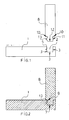
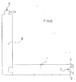
- sheet 1 is lateral view of the joint with the parts to be connected not assembled.
- Figure 2 is transversal section view of the parts assembled in the joint.
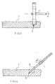
- sheet 2 figure 3 is section view on transversal plane to the advancement way of the board in working in the step of realization of the hollow.
- Figure 4 is view in section on transversal plane to the advancement way in the step of realization of the groove.
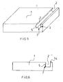
- sheet 3 figure 5 is perspective view of the hollow with the groove realized on the upper face of the plane board.
- Figure 6 is lateral view of an other method to realize the hollow with groove, i.e. with chamfer.
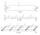
- figure 7 is lateral view of a single board having hollow with groove at a border and at the other border outside profile with the same shape and dimension for the longitudinal sliding joint between boards of the same type.
- Figure 8 is lateral view of more boards connected by joint.
- Figure 9 is perspective view of connected boards to realize a plane surface.
- sheet 5 figure 10 is lateral view of connected boards with lateral sliding joint with surfaces perpendicular each other.
- sheet 6 figure 11 is perspective view of an embodiment with realization of a structure having connected boards to form plane surfaces e for surfaces perpendicular each other.
- the joint consists of a level board 1 on which is carried out a hollow 2 with inside walls 3 perpendicular to one another.
- This working is actuated by means of surface cylindrical cutter 4 with axis of rotation of the cutting tool horizontal for peripheral milling with high cutting speed.
- a groove 5 is realized, instead of with the conventional cutters with angulated bit, i.e. with cutters for hollow with frontal milling, by circular saw 6, placed with angulation and depth of cut to obtain the inside profile 7 of the hollow 2.
- the circular saw 6 can be changed with dish cutter with limited axial extension of the cutting tools to realize not a frontal milling but a peripheral milling with high cutting speed.
- On further board 8 is realized an outside profile 9 equal and complementary to the inside profile 7, i.e. having shape and dimensions suitable to the longitudinal sliding joint of the boards 1 and 8 perpendicular between them.
- the use in subsequent and onto a same machinery of the surface cylindrical cutter 4 with rotation axis of the tool horizontal and of the circular saw 6 or the disk cutter for peripheral milling in linear advancement of the board permits to have the inside profile 7 of the hollow 2 in extremely quick time.
- the profile 9 consists of a beating parts 10 with surfaces 11 and 12 perpendicular each other and protruding part 13 having the same shape and dimension of the groove 5.
- the hollow 2 can be realized onto one or more faces of the level board 1 or on the border of the said level board, so to respectively obtain joint between the boards perpendicular each other or joints with boards of the same type with joint each other to obtain level surfaces.
- the hollows 2 and the grooves 5 both onto the border than onto the faces is possible to obtain level surfaces and perpendicular each other to have sides and corners.
- the hollow 2 can have, long a vertical wall, a chamfer 14 to be obtained with circular saw 6 to have bigger angulation of the circular saw 6 in realization step of the groove 5.
- the board 1 may have any shape on the base of the use necessity.
- the invented joint can provide variations all part of the inventive step. The materials on which the joint is to be realized with its working are to be changed on the base of the use necessity. Moreover, all technical details can be changed with other similar ones.
Landscapes
- Engineering & Computer Science (AREA)
- General Engineering & Computer Science (AREA)
- Mechanical Engineering (AREA)
- Support Devices For Sliding Doors (AREA)
Abstract
Description
- The invention refers to a joint for boards in wood or in any other material and to the method to realize part of this joint, obtained with high speed of manufacturing. In the workings on wood or on other materials different types of joint are known and the pertinent workings to obtain said joints. In the art the profile of the joints is essentially obtained with milling machines, i.e. working centres that use workings of frontal milling by tools with vertical rotation axis and plane-conical bits and/or tools for shoulders. The use of the frontal milling in the workings onto hollow parts, however, limits the production speed. In the art and with the profiles with joints known are produced, in plane workings, ten metres per minute with died times between a worked piece and the subsequent one to be worked. Realizing the joint by the invented method are obtained, on an average, eighty metres per minute of ended goods in plane workings. Besides to the economic advantage obtained with the increasing of the productivity, the invented longitudinal sliding joint has the possibility to realize the union of boards both to have plane surfaces than to obtain surfaces perpendicular each other, such as surfaces consist of plane and perpendicular surfaces. The longitudinal sliding joint is realized with groove onto an inside wall of the hollow and such groove is not realized by cutter with angulated bits (cutter for hollows) but by circular saw that cuts the groove with high speed or, in equal way, by circular cutter with limited axial extension of the bits that cuts the groove with high speed such as it arranges a peripheral milling and not a frontal milling. The invention is illustrated in a merely indicative and not limiting way in the drawings of
sheets sheet 1figure 1 is lateral view of the joint with the parts to be connected not assembled.Figure 2 is transversal section view of the parts assembled in the joint. Insheet 2figure 3 is section view on transversal plane to the advancement way of the board in working in the step of realization of the hollow.Figure 4 is view in section on transversal plane to the advancement way in the step of realization of the groove. Insheet 3figure 5 is perspective view of the hollow with the groove realized on the upper face of the plane board.Figure 6 is lateral view of an other method to realize the hollow with groove, i.e. with chamfer. In sheet 4figure 7 is lateral view of a single board having hollow with groove at a border and at the other border outside profile with the same shape and dimension for the longitudinal sliding joint between boards of the same type.Figure 8 is lateral view of more boards connected by joint.Figure 9 is perspective view of connected boards to realize a plane surface. Insheet 5figure 10 is lateral view of connected boards with lateral sliding joint with surfaces perpendicular each other. In sheet 6figure 11 is perspective view of an embodiment with realization of a structure having connected boards to form plane surfaces e for surfaces perpendicular each other. In a preferred embodiment but not exclusive the joint consists of alevel board 1 on which is carried out a hollow 2 withinside walls 3 perpendicular to one another. This working is actuated by means of surface cylindrical cutter 4 with axis of rotation of the cutting tool horizontal for peripheral milling with high cutting speed. At a vertical wall of the hollow 2 agroove 5 is realized, instead of with the conventional cutters with angulated bit, i.e. with cutters for hollow with frontal milling, by circular saw 6, placed with angulation and depth of cut to obtain theinside profile 7 of the hollow 2. In further embodiment the circular saw 6 can be changed with dish cutter with limited axial extension of the cutting tools to realize not a frontal milling but a peripheral milling with high cutting speed. Onfurther board 8 is realized anoutside profile 9 equal and complementary to theinside profile 7, i.e. having shape and dimensions suitable to the longitudinal sliding joint of theboards inside profile 7 of the hollow 2 in extremely quick time. Theprofile 9 consists of a beatingparts 10 withsurfaces 11 and 12 perpendicular each other and protrudingpart 13 having the same shape and dimension of thegroove 5. The hollow 2 can be realized onto one or more faces of thelevel board 1 or on the border of the said level board, so to respectively obtain joint between the boards perpendicular each other or joints with boards of the same type with joint each other to obtain level surfaces. Placing thehollows 2 and thegrooves 5 both onto the border than onto the faces is possible to obtain level surfaces and perpendicular each other to have sides and corners. In a further embodiment the hollow 2 can have, long a vertical wall, achamfer 14 to be obtained with circular saw 6 to have bigger angulation of the circular saw 6 in realization step of thegroove 5. Theboard 1 may have any shape on the base of the use necessity. The invented joint can provide variations all part of the inventive step. The materials on which the joint is to be realized with its working are to be changed on the base of the use necessity. Moreover, all technical details can be changed with other similar ones.
Claims (8)
- Longitudinal sliding joint comprising a level board (1) on which is carried out a hollow (2) with inside walls (3) perpendicular to one another characterized in that to have a groove (5) and an inside profile (7) in which comes to longitudinally slide an outside profile (9) of an other level board equal and complementary to the inside profile (7), with the profile (9) consists of a beating parts (10) with surfaces (11, 12) perpendicular each other and protruding part (13) having the same shape and dimension of the groove (5).
- Longitudinal sliding joint, as per claim 1, characterized in that the hollow (2) can be realized onto one or more faces of the level board (1) or to the border of the level board, so to respectively obtain joint between the boards perpendicular each other or joints with boards of the same type with joint each other to obtain level surfaces.
- Longitudinal sliding joint, as to the previous claims, characterized in that placing the hollows (2) and the grooves (5) both onto the border than onto the faces is possible to obtain level surfaces and perpendicular each other to obtain sides and corners.
- Longitudinal sliding joint, as to the previous claims, characterized in that the hollow (2) can have, long a vertical wall, a chamfer (14).
- Longitudinal sliding joint, as to the previous claims, characterized in that the board (1) may have any shape on the base of the use necessity and that the board (1) can be realized in wood or other material.
- Longitudinal sliding joint, as to the previous claims, characterized in that the hollow (2) is actuated by means of surface cylindrical cutter (4) with axis of rotation of the cutting tool horizontal and by peripheral milling with cutting highspeed and with the groove (5) to be obtained by a circular saw prepared with angle and depth of cutting to obtain the inside profile of the hollow (2).
- Longitudinal sliding joint, as per claims 1, 2, 3, 4 and 5, characterized in that the hollow (5) is obtained by means of surface cylindrical cutter (4) with axis of rotation of the cutting tool horizontal and by peripheral milling with cutting highspeed and with the groove (5) to be obtained by a disk cutter with limited axial extension of the cutting tools to actuate a peripheral milling with cutting highspeed.
- Longitudinal sliding joint, as to the claims 6 or 7, characterized in that the use in sequence and onto the same machinery of the surface cylindrical cutter (4) with axis of rotation of the cutting tools horizontal for peripheral milling and of the circular saw (6) or of the disk cutter with limited axial extension of the cutting tools for peripheral milling, in linear advancement of the level board (1), permits to obtain the inside profile (7) of the hollow in very quick times.
Priority Applications (1)
| Application Number | Priority Date | Filing Date | Title |
|---|---|---|---|
| EP09014953A EP2333353A3 (en) | 2009-12-02 | 2009-12-02 | Longitudinal sliding joint |
Applications Claiming Priority (1)
| Application Number | Priority Date | Filing Date | Title |
|---|---|---|---|
| EP09014953A EP2333353A3 (en) | 2009-12-02 | 2009-12-02 | Longitudinal sliding joint |
Publications (2)
| Publication Number | Publication Date |
|---|---|
| EP2333353A2 true EP2333353A2 (en) | 2011-06-15 |
| EP2333353A3 EP2333353A3 (en) | 2012-07-25 |
Family
ID=46319953
Family Applications (1)
| Application Number | Title | Priority Date | Filing Date |
|---|---|---|---|
| EP09014953A Withdrawn EP2333353A3 (en) | 2009-12-02 | 2009-12-02 | Longitudinal sliding joint |
Country Status (1)
| Country | Link |
|---|---|
| EP (1) | EP2333353A3 (en) |
Cited By (32)
| Publication number | Priority date | Publication date | Assignee | Title |
|---|---|---|---|---|
| EP2476918A1 (en) * | 2011-01-17 | 2012-07-18 | Hans Hundegger | Dovetail connection |
| WO2017135874A1 (en) * | 2016-02-04 | 2017-08-10 | Välinge Innovation AB | A set of panels for an assembled product |
| US9945121B2 (en) | 2015-12-03 | 2018-04-17 | Valinge Innovation Ab | Panels comprising a mechanical locking device and an assembled product comprising the panels |
| US10034541B2 (en) | 2014-12-19 | 2018-07-31 | Valinge Innovation Ab | Panels comprising a mechanical locking device and an assembled product comprising the panels |
| US10202996B2 (en) | 2011-05-06 | 2019-02-12 | Valinge Innovation Ab | Mechanical locking system for building panels |
| US10415613B2 (en) | 2016-02-09 | 2019-09-17 | Valinge Innovation Ab | Set of panel-shaped elements for a composed element |
| US10448739B2 (en) | 2015-09-22 | 2019-10-22 | Valinge Innovation Ab | Panels comprising a mechanical locking device and an assembled product comprising the panels |
| US10451097B2 (en) | 2013-09-16 | 2019-10-22 | Valinge Innovation Ab | Assembled product and a method of assembling the assembled product |
| US10486245B2 (en) | 2016-02-09 | 2019-11-26 | Valinge Innovation Ab | Element and method for providing dismantling groove |
| US10548397B2 (en) | 2016-01-26 | 2020-02-04 | Valinge Innovation Ab | Panels comprising a mechanical locking device and an assembled product comprising the panels |
| CN110959536A (en) * | 2018-10-01 | 2020-04-07 | 智能宠物家庭办公室公司 | Removable hiding structure for small animal residence |
| US10670064B2 (en) | 2015-04-21 | 2020-06-02 | Valinge Innovation Ab | Panel with a slider |
| US10724564B2 (en) | 2016-10-27 | 2020-07-28 | Valinge Innovation Ab | Set of panels with a mechanical locking device |
| US10736416B2 (en) | 2018-03-23 | 2020-08-11 | Valinge Innovation Ab | Panels comprising a mechanical locking device and an assembled product comprising the panels |
| US10830268B2 (en) | 2014-01-10 | 2020-11-10 | Valinge Innovation Ab | Furniture panel |
| US10830266B2 (en) | 2016-02-15 | 2020-11-10 | Valinge Innovation Ab | Method for forming a panel |
| US10876563B2 (en) | 2013-09-16 | 2020-12-29 | Valinge Innovation Ab | Assembled product and a method of assembling the product |
| US10876562B2 (en) | 2014-05-09 | 2020-12-29 | Valinge Innovation Ab | Mechanical locking system for building panels |
| US10968936B2 (en) | 2015-04-30 | 2021-04-06 | Valinge Innovation Ab | Panel with a fastening device |
| SE1951500A1 (en) * | 2019-12-18 | 2021-06-19 | Vilox Ab | Joining system for furniture |
| US11076691B2 (en) | 2018-04-18 | 2021-08-03 | Valinge Innovation Ab | Set of panels with a mechanical locking device |
| US11172647B2 (en) | 2018-10-01 | 2021-11-16 | PetSmart Home Office, Inc. | System and method for coupling an exercise wheel accessory to a small animal habitat |
| US11272783B2 (en) | 2017-12-22 | 2022-03-15 | Valinge Innovation Ab | Set of panels |
| US11371542B2 (en) | 2017-12-22 | 2022-06-28 | Valinge Innovation Ab | Set of panels |
| US11448249B2 (en) | 2014-01-10 | 2022-09-20 | Valinge Innovation Ab | Panels comprising a mechanical locking device and an assembled product comprising the panels |
| US11445819B2 (en) | 2018-08-30 | 2022-09-20 | Valinge Innovation Ab | Set of panels with a mechanical locking device |
| US11448252B2 (en) | 2018-04-18 | 2022-09-20 | Valinge Innovation Ab | Set of panels with a mechanical locking device |
| US11506235B2 (en) | 2017-05-15 | 2022-11-22 | Valinge Innovation Ab | Elements and a locking device for an assembled product |
| US11536307B2 (en) | 2018-04-18 | 2022-12-27 | Valinge Innovation Ab | Symmetric tongue and t-cross |
| US11614114B2 (en) | 2018-04-19 | 2023-03-28 | Valinge Innovation Ab | Panels for an assembled product |
| US11703072B2 (en) | 2018-04-18 | 2023-07-18 | Valinge Innovation Ab | Set of panels with a mechanical locking device |
| US12495898B2 (en) | 2018-08-30 | 2025-12-16 | Välinge Innovation AB | Set of panels with a mechanical locking device |
Family Cites Families (4)
| Publication number | Priority date | Publication date | Assignee | Title |
|---|---|---|---|---|
| DE29911462U1 (en) * | 1999-07-02 | 1999-11-18 | Akzenta Paneele & Profile Gmbh | Fastening system for panels |
| US6546691B2 (en) * | 2000-12-13 | 2003-04-15 | Kronospan Technical Company Ltd. | Method of laying panels |
| EP1789642B1 (en) * | 2004-09-17 | 2013-05-01 | Dirk Dammers | Panel in particular floor panel |
| DE202006005470U1 (en) * | 2006-04-05 | 2006-07-27 | Hdm Gmbh | Clamp for fixing panel elements |
-
2009
- 2009-12-02 EP EP09014953A patent/EP2333353A3/en not_active Withdrawn
Cited By (60)
| Publication number | Priority date | Publication date | Assignee | Title |
|---|---|---|---|---|
| EP2476918A1 (en) * | 2011-01-17 | 2012-07-18 | Hans Hundegger | Dovetail connection |
| US10871179B2 (en) | 2011-05-06 | 2020-12-22 | Valinge Innovation Ab | Mechanical locking system for building panels |
| US11428253B2 (en) | 2011-05-06 | 2022-08-30 | Valinge Innovation Ab | Mechanical locking system for building panels |
| US10202996B2 (en) | 2011-05-06 | 2019-02-12 | Valinge Innovation Ab | Mechanical locking system for building panels |
| US11781577B2 (en) | 2011-05-06 | 2023-10-10 | Valinge Innovation Ab | Mechanical locking system for building panels |
| US12276293B2 (en) | 2011-05-06 | 2025-04-15 | Välinge Innovation AB | Mechanical locking system for building panels |
| US11204051B2 (en) | 2013-09-16 | 2021-12-21 | Valinge Innovation Ab | Assembled product and a method of assembling the assembled product |
| US10876563B2 (en) | 2013-09-16 | 2020-12-29 | Valinge Innovation Ab | Assembled product and a method of assembling the product |
| US11680596B2 (en) | 2013-09-16 | 2023-06-20 | Valinge Innovation Ab | Assembled product and a method of assembling the assembled product |
| US11649843B2 (en) | 2013-09-16 | 2023-05-16 | Valinge Innovation Ab | Assembled product and a method of assembling the product |
| US10451097B2 (en) | 2013-09-16 | 2019-10-22 | Valinge Innovation Ab | Assembled product and a method of assembling the assembled product |
| US10731688B2 (en) * | 2013-09-16 | 2020-08-04 | Valinge Innovation Ab | Assembled product and a method of assembling the assembled product |
| US11448249B2 (en) | 2014-01-10 | 2022-09-20 | Valinge Innovation Ab | Panels comprising a mechanical locking device and an assembled product comprising the panels |
| US10830268B2 (en) | 2014-01-10 | 2020-11-10 | Valinge Innovation Ab | Furniture panel |
| US11326636B2 (en) | 2014-05-09 | 2022-05-10 | Valinge Innovation Ab | Mechanical locking system for building panels |
| US10876562B2 (en) | 2014-05-09 | 2020-12-29 | Valinge Innovation Ab | Mechanical locking system for building panels |
| US11885355B2 (en) | 2014-05-09 | 2024-01-30 | Välinge Innovation AB | Mechanical locking system for building panels |
| US10506875B2 (en) | 2014-12-19 | 2019-12-17 | Valinge Innovation Ab | Panels comprising a mechanical locking device and an assembled product comprising the panels |
| US11083287B2 (en) | 2014-12-19 | 2021-08-10 | Valinge Innovation Ab | Panels comprising a mechanical locking device and an assembled product comprising the panels |
| US10034541B2 (en) | 2014-12-19 | 2018-07-31 | Valinge Innovation Ab | Panels comprising a mechanical locking device and an assembled product comprising the panels |
| US10670064B2 (en) | 2015-04-21 | 2020-06-02 | Valinge Innovation Ab | Panel with a slider |
| US10968936B2 (en) | 2015-04-30 | 2021-04-06 | Valinge Innovation Ab | Panel with a fastening device |
| US11246415B2 (en) | 2015-09-22 | 2022-02-15 | Valinge Innovation Ab | Panels comprising a mechanical locking device and an assembled product comprising the panels |
| US10448739B2 (en) | 2015-09-22 | 2019-10-22 | Valinge Innovation Ab | Panels comprising a mechanical locking device and an assembled product comprising the panels |
| US10669716B2 (en) | 2015-12-03 | 2020-06-02 | Valinge Innovation Ab | Panels comprising a mechanical locking device and an assembled product comprising the panels |
| US9945121B2 (en) | 2015-12-03 | 2018-04-17 | Valinge Innovation Ab | Panels comprising a mechanical locking device and an assembled product comprising the panels |
| US11098484B2 (en) | 2015-12-03 | 2021-08-24 | Valinge Innovation Ab | Panels comprising a mechanical locking device and an assembled product comprising the panels |
| US11445820B2 (en) | 2016-01-26 | 2022-09-20 | Valinge Innovation Ab | Panels comprising a mechanical locking device and an assembled product comprising the panels |
| US12453413B2 (en) | 2016-01-26 | 2025-10-28 | Välinge Innovation AB | Panels comprising a mechanical locking device and an assembled product comprising the panels |
| US10548397B2 (en) | 2016-01-26 | 2020-02-04 | Valinge Innovation Ab | Panels comprising a mechanical locking device and an assembled product comprising the panels |
| US11137007B2 (en) | 2016-02-04 | 2021-10-05 | Valinge Innovation Ab | Set of panels for an assembled product |
| WO2017135874A1 (en) * | 2016-02-04 | 2017-08-10 | Välinge Innovation AB | A set of panels for an assembled product |
| CN108496013A (en) * | 2016-02-04 | 2018-09-04 | 瓦林格创新股份有限公司 | One group of panelling for assembling product |
| US10544818B2 (en) | 2016-02-04 | 2020-01-28 | Valinge Innovation Ab | Set of panels for an assembled product |
| US10415613B2 (en) | 2016-02-09 | 2019-09-17 | Valinge Innovation Ab | Set of panel-shaped elements for a composed element |
| US10486245B2 (en) | 2016-02-09 | 2019-11-26 | Valinge Innovation Ab | Element and method for providing dismantling groove |
| US10830266B2 (en) | 2016-02-15 | 2020-11-10 | Valinge Innovation Ab | Method for forming a panel |
| US10724564B2 (en) | 2016-10-27 | 2020-07-28 | Valinge Innovation Ab | Set of panels with a mechanical locking device |
| US11506235B2 (en) | 2017-05-15 | 2022-11-22 | Valinge Innovation Ab | Elements and a locking device for an assembled product |
| US11272783B2 (en) | 2017-12-22 | 2022-03-15 | Valinge Innovation Ab | Set of panels |
| US11371542B2 (en) | 2017-12-22 | 2022-06-28 | Valinge Innovation Ab | Set of panels |
| US10736416B2 (en) | 2018-03-23 | 2020-08-11 | Valinge Innovation Ab | Panels comprising a mechanical locking device and an assembled product comprising the panels |
| US11536307B2 (en) | 2018-04-18 | 2022-12-27 | Valinge Innovation Ab | Symmetric tongue and t-cross |
| US11933335B2 (en) | 2018-04-18 | 2024-03-19 | Valinge Innovation Ab | Symmetric tongue and T-cross |
| US11448252B2 (en) | 2018-04-18 | 2022-09-20 | Valinge Innovation Ab | Set of panels with a mechanical locking device |
| US11076691B2 (en) | 2018-04-18 | 2021-08-03 | Valinge Innovation Ab | Set of panels with a mechanical locking device |
| US11703072B2 (en) | 2018-04-18 | 2023-07-18 | Valinge Innovation Ab | Set of panels with a mechanical locking device |
| US12320374B2 (en) | 2018-04-18 | 2025-06-03 | Välinge Innovation AB | Symmetric tongue and T-cross |
| US11614114B2 (en) | 2018-04-19 | 2023-03-28 | Valinge Innovation Ab | Panels for an assembled product |
| US11445819B2 (en) | 2018-08-30 | 2022-09-20 | Valinge Innovation Ab | Set of panels with a mechanical locking device |
| US12495898B2 (en) | 2018-08-30 | 2025-12-16 | Välinge Innovation AB | Set of panels with a mechanical locking device |
| US12408748B2 (en) | 2018-08-30 | 2025-09-09 | Välinge Innovation AB | Set of panels with a mechanical locking device |
| CN110959536A (en) * | 2018-10-01 | 2020-04-07 | 智能宠物家庭办公室公司 | Removable hiding structure for small animal residence |
| US11206808B2 (en) * | 2018-10-01 | 2021-12-28 | PetSmart Home Office, Inc. | Removable hide for small animal habitat |
| US11172647B2 (en) | 2018-10-01 | 2021-11-16 | PetSmart Home Office, Inc. | System and method for coupling an exercise wheel accessory to a small animal habitat |
| EP4077951A4 (en) * | 2019-12-18 | 2024-02-07 | Vilox AB | CONNECTING SYSTEM FOR FURNITURE |
| WO2021126048A1 (en) * | 2019-12-18 | 2021-06-24 | Vilox Ab | Joining system for furniture |
| SE544408C2 (en) * | 2019-12-18 | 2022-05-10 | Vilox Ab | Joining system for furniture, furniture portion comprising the joining system and method for manufacturing the joining element of the joining system |
| US12433401B2 (en) | 2019-12-18 | 2025-10-07 | Vilox Systems Ab | Joining system for furniture |
| SE1951500A1 (en) * | 2019-12-18 | 2021-06-19 | Vilox Ab | Joining system for furniture |
Also Published As
| Publication number | Publication date |
|---|---|
| EP2333353A3 (en) | 2012-07-25 |
Similar Documents
| Publication | Publication Date | Title |
|---|---|---|
| US4643237A (en) | Method for fabricating molding or slotting boards such as shutter slats, molding for carpentry or for construction and apparatus for practicing this process | |
| CN113490582B (en) | Cutting device for a continuous milling machine and method for manufacturing a panel | |
| CA2712359A1 (en) | Dual cutter router bit | |
| CN201619140U (en) | Veneered foam heated board V-groove groover | |
| CN202506879U (en) | One-step molding drill tool | |
| US20140290798A1 (en) | Triple cutter router bit | |
| CN104441067A (en) | High-strength timber cutting machine | |
| CN104972527A (en) | Multifunctional mortise and tenon machine and implementing method thereof | |
| CN108817427A (en) | A kind of high-efficiency high-accuracy NC cutting tool hole boring cutter rod | |
| CN202640487U (en) | Machining device for machining round bamboo material to be in hexagonal prism shape | |
| CN201525070U (en) | Workpiece fabricating machine | |
| CN202447690U (en) | Novel lathe tool | |
| CN101524861B (en) | Inclined mortising and tenoning machine | |
| CN212331321U (en) | Multifunctional semi-automatic wood craft manufacturing machine | |
| CN101850515A (en) | Multi-station combined machine tool | |
| CN101697330B (en) | Keycap, manufacturing method thereof, and workpiece manufacturing machine | |
| CN201385346Y (en) | Slope mortise and tenon machine | |
| CN204657658U (en) | A kind of roller gear gear shapping machine | |
| ITBO20080728A1 (en) | JOINT TO LONGITUDINAL SLIDING AND PRODUCTION METHOD | |
| JP6979830B2 (en) | Manufacturing method of decorative panel | |
| TWI587950B (en) | Butterfly milling method | |
| CN202271143U (en) | Overall clamping cutting device of spiral cutting tool blades | |
| CN219818069U (en) | Double-chamfering tool | |
| CN204160558U (en) | One horizontally slips by the interchangeable mitre saw of grid | |
| KR100948215B1 (en) | Circular saw side cutting method |
Legal Events
| Date | Code | Title | Description |
|---|---|---|---|
| PUAI | Public reference made under article 153(3) epc to a published international application that has entered the european phase |
Free format text: ORIGINAL CODE: 0009012 |
|
| AK | Designated contracting states |
Kind code of ref document: A2 Designated state(s): AT BE BG CH CY CZ DE DK EE ES FI FR GB GR HR HU IE IS IT LI LT LU LV MC MK MT NL NO PL PT RO SE SI SK SM TR |
|
| AX | Request for extension of the european patent |
Extension state: AL BA RS |
|
| RIN1 | Information on inventor provided before grant (corrected) |
Inventor name: MUSIO, ANTONIO |
|
| PUAL | Search report despatched |
Free format text: ORIGINAL CODE: 0009013 |
|
| AK | Designated contracting states |
Kind code of ref document: A3 Designated state(s): AT BE BG CH CY CZ DE DK EE ES FI FR GB GR HR HU IE IS IT LI LT LU LV MC MK MT NL NO PL PT RO SE SI SK SM TR |
|
| AX | Request for extension of the european patent |
Extension state: AL BA RS |
|
| RIC1 | Information provided on ipc code assigned before grant |
Ipc: F16B 5/00 20060101AFI20120619BHEP Ipc: F16B 12/12 20060101ALI20120619BHEP |
|
| STAA | Information on the status of an ep patent application or granted ep patent |
Free format text: STATUS: THE APPLICATION IS DEEMED TO BE WITHDRAWN |
|
| 18D | Application deemed to be withdrawn |
Effective date: 20120703 |