EP2332836A2 - Flow control for on-board inert gas generation system - Google Patents
Flow control for on-board inert gas generation system Download PDFInfo
- Publication number
- EP2332836A2 EP2332836A2 EP20100012368 EP10012368A EP2332836A2 EP 2332836 A2 EP2332836 A2 EP 2332836A2 EP 20100012368 EP20100012368 EP 20100012368 EP 10012368 A EP10012368 A EP 10012368A EP 2332836 A2 EP2332836 A2 EP 2332836A2
- Authority
- EP
- European Patent Office
- Prior art keywords
- fuel tank
- nitrogen
- separation module
- control valve
- flow rate
- Prior art date
- Legal status (The legal status is an assumption and is not a legal conclusion. Google has not performed a legal analysis and makes no representation as to the accuracy of the status listed.)
- Granted
Links
Images

Classifications
-
- B—PERFORMING OPERATIONS; TRANSPORTING
- B65—CONVEYING; PACKING; STORING; HANDLING THIN OR FILAMENTARY MATERIAL
- B65D—CONTAINERS FOR STORAGE OR TRANSPORT OF ARTICLES OR MATERIALS, e.g. BAGS, BARRELS, BOTTLES, BOXES, CANS, CARTONS, CRATES, DRUMS, JARS, TANKS, HOPPERS, FORWARDING CONTAINERS; ACCESSORIES, CLOSURES, OR FITTINGS THEREFOR; PACKAGING ELEMENTS; PACKAGES
- B65D90/00—Component parts, details or accessories for large containers
- B65D90/22—Safety features
- B65D90/38—Means for reducing the vapour space or for reducing the formation of vapour within containers
- B65D90/44—Means for reducing the vapour space or for reducing the formation of vapour within containers by use of inert gas for filling space above liquid or between contents
-
- A—HUMAN NECESSITIES
- A62—LIFE-SAVING; FIRE-FIGHTING
- A62C—FIRE-FIGHTING
- A62C3/00—Fire prevention, containment or extinguishing specially adapted for particular objects or places
- A62C3/07—Fire prevention, containment or extinguishing specially adapted for particular objects or places in vehicles, e.g. in road vehicles
- A62C3/08—Fire prevention, containment or extinguishing specially adapted for particular objects or places in vehicles, e.g. in road vehicles in aircraft
-
- A—HUMAN NECESSITIES
- A62—LIFE-SAVING; FIRE-FIGHTING
- A62C—FIRE-FIGHTING
- A62C99/00—Subject matter not provided for in other groups of this subclass
- A62C99/0009—Methods of extinguishing or preventing the spread of fire by cooling down or suffocating the flames
- A62C99/0018—Methods of extinguishing or preventing the spread of fire by cooling down or suffocating the flames using gases or vapours that do not support combustion, e.g. steam, carbon dioxide
-
- B—PERFORMING OPERATIONS; TRANSPORTING
- B64—AIRCRAFT; AVIATION; COSMONAUTICS
- B64D—EQUIPMENT FOR FITTING IN OR TO AIRCRAFT; FLIGHT SUITS; PARACHUTES; ARRANGEMENT OR MOUNTING OF POWER PLANTS OR PROPULSION TRANSMISSIONS IN AIRCRAFT
- B64D37/00—Arrangements in connection with fuel supply for power plant
- B64D37/32—Safety measures not otherwise provided for, e.g. preventing explosive conditions
-
- Y—GENERAL TAGGING OF NEW TECHNOLOGICAL DEVELOPMENTS; GENERAL TAGGING OF CROSS-SECTIONAL TECHNOLOGIES SPANNING OVER SEVERAL SECTIONS OF THE IPC; TECHNICAL SUBJECTS COVERED BY FORMER USPC CROSS-REFERENCE ART COLLECTIONS [XRACs] AND DIGESTS
- Y10—TECHNICAL SUBJECTS COVERED BY FORMER USPC
- Y10T—TECHNICAL SUBJECTS COVERED BY FORMER US CLASSIFICATION
- Y10T137/00—Fluid handling
- Y10T137/0318—Processes
- Y10T137/0324—With control of flow by a condition or characteristic of a fluid
-
- Y—GENERAL TAGGING OF NEW TECHNOLOGICAL DEVELOPMENTS; GENERAL TAGGING OF CROSS-SECTIONAL TECHNOLOGIES SPANNING OVER SEVERAL SECTIONS OF THE IPC; TECHNICAL SUBJECTS COVERED BY FORMER USPC CROSS-REFERENCE ART COLLECTIONS [XRACs] AND DIGESTS
- Y10—TECHNICAL SUBJECTS COVERED BY FORMER USPC
- Y10T—TECHNICAL SUBJECTS COVERED BY FORMER US CLASSIFICATION
- Y10T137/00—Fluid handling
- Y10T137/2931—Diverse fluid containing pressure systems
- Y10T137/3115—Gas pressure storage over or displacement of liquid
- Y10T137/3127—With gas maintenance or application
Definitions
- This invention relates to a fuel tank inerting system, and more particularly to a process and device for controlling oxygen content within a fuel tank.
- An aircraft fuel tank includes a liquid fuel filled portion and a fuel vapor filled portion known as the fuel tank ullage.
- Oxygen mixed with the fuel vapor within the ullage creates a potentially hazardous condition.
- Systems that replace oxygen-containing air with an inert gas substantially reduce the risks of this potentially hazardous condition.
- Some systems utilize tanks of nitrogen rich air for replacing the oxygen containing air within the fuel tank ullage.
- An on-board inert gas generating system that replaces oxygen rich air with nitrogen-enriched air is currently under development for use in aircraft.
- On-board inert gas generating systems utilize an air separation module that removes oxygen to produce a nitrogen-enriched air stream that fills the fuel tank ullage.
- the fuel tank is vented to the ambient environment and experiences changes in pressure responsive to changes in altitude. Changes in ambient pressure affect the performance of the air separation module and the rate of flow of nitrogen-enriched air into the fuel tank ullage. Such changes in the rate of flow of nitrogen-enriched air result in a change in the amount of oxygen within the fuel tank.
- An on-board inert gas generating system includes a flow control valve modulated according to changes in ambient conditions to minimize changes to oxygen content with a fuel tank.
- the example on-board inert gas generating system includes an air separation module that removes oxygen from an air stream and supplies a nitrogen-enriched air stream to the fuel tank. The removed oxygen is exhausted overboard.
- an air separation module that removes oxygen from an air stream and supplies a nitrogen-enriched air stream to the fuel tank. The removed oxygen is exhausted overboard.
- pressure and temperature within the fuel tank change with ambient conditions.
- the quality of the nitrogen-enriched air stream provided by the air separation module varies with the ambient conditions. Higher flow rates through the air separation module removes less oxygen relative to lower flow rates.
- the variations in pressure and temperature of the fuel tank ullage varies responsive to altitude causes variation in the flow rate through the air separation module that in turn affect the overall amount of oxygen within the nitrogen-enriched air stream that is provided to the fuel tank ullage.
- the amount of flow through the air separation module that produces least amount of oxygen within the nitrogen-enriched air stream is determined and a flow control valve modulated to provide the determined flow rate.
- the flow control valve is operated by an electronic controller to provide a desired flow rate through the air separation module that produces the smallest change in oxygen content within the fuel tank ullage.
- an example of an on-board inert gas generating system (OBIGGS) 10 is shown and includes an air separation module 12 that removes oxygen from manifold bleed airflow 14.
- the air separation module 12 removes oxygen from the high pressure air stream 14 and supplies a nitrogen-enriched air stream 16 to a fuel tank 18.
- An oxygen stream 22 from the air separation module 12 is exhausted overboard.
- the example fuel tank 18 includes a vent 20 to the ambient environment. The vent 20 causes changes in pressure and temperature within the fuel tank 18 responsive to changes in ambient conditions.
- the system 10 includes a heat exchanger 32 provided to regulate the temperature of the high pressure air stream 14.
- the example heat exchanger 32 exchanges heat between the bleed airflow 14 and ram airflow 34 drawn from a ram air passage 36.
- the ram airflow 34 moves at a relatively high flow rate as compared to the bleed airflow 14.
- the high flow rate of the ram airflow 34 is utilized to draw air through the heat exchanger 32 and through the air separation module 12.
- An ejector 38 communicates high pressure airflow 47 to produce a low-pressure region at an outlet 40 of the air separation module 12.
- the low-pressure region is produced by the relatively high flow of the high pressure airflow 34 at the outlet 40 and produces the required pressure drop that draws bleed airflow 14 through the air separation module 12.
- a second nozzle 42 produces a low-pressure region adjacent an outlet 44 of the heat exchange 32.
- the low pressure produced by the relative high flow of the high pressure airflow 34 produces the pressure drop that drives airflow through the heat exchanger 32.
- the mechanism that drives airflow through the air separation module 12 and heat exchanger 32 is known, and a worker versed in the art would understand that other methods and systems for driving airflow are within the contemplation of this invention.
- the quality of the nitrogen-enriched air stream 16 provided by the air separation module 12 varies given ambient conditions, and a rate of flow. Higher flow rates through the air separation module 12 remove less oxygen relative to lower flow rates.
- the pressure and temperature within the fuel tank ullage 24 varies responsive to changes in ambient conditions due to communication with ambient conditions through the vent 20. At higher altitudes, the pressure within the fuel tank 18 is at a low level. During descent, ambient pressure, and therefore pressure within the fuel tank 18 increases. The flow rate through the air separation module 12 varies responsive to these changes in ambient conditions affecting the overall amount of oxygen within the nitrogen-enriched air stream 16 that is provided to the fuel tank ullage 24.
- the amount of flow through the air separation module 12 that produces the optimal, or least amount of oxygen within the fuel tank ullage 24 is determined and controlled by modulating a flow control valve 28.
- a backflow prevention valve 29 is provided downstream of the flow control valve 28 to prevent back flow from the fuel tank 18.
- a first sensor 46 provides pressure and temperature information to the controller 30.
- a second sensor 25 provides information to the controller 30 indicative of conditions within the fuel tank 18.
- the controller 30 in turn modulates the flow control valve 28 to provide a flow rate of the nitrogen-enriched air stream 16 through the air separation module 12 that results in the least amount of oxygen within the fuel tank ullage 24.
- An inlet pressure sensor 13 and an outlet pressure sensor 15 provide information on pressure into and out of the air separation module 12.
- a temperature sensor 17 provides information on the temperature of the bleed airflow 14. The volume and rate of airflow through the air separation module 12 is limited. Therefore, the controller 30 modulates the flow control valve 28 to provide a flow rate through the air separation module 12 that produces the smallest change in oxygen content within the fuel tank ullage 24.
- the example flow control valve 28 is shown schematically and includes a valve plate 48 that is rotated by a motor 50.
- the example motor 50 is a torque motor commanded by the controller 30.
- the motor 50 opens and closes the flow passage 52 to control the nitrogen-enriched air stream 16.
- the valve plate 48 can be opened and closed to provide a continuously variable opening 54 that provides control over the nitrogen-enriched air stream 16.
- the controller 30 can be a commercially available microprocessor as known in the art. A worker versed in the art with the benefit of this disclosure would understand how to program a commercially available microprocessor to command the flow control valve 28.
- pressure within the fuel tank ullage 24 changes responsive to ambient pressures.
- the pressure inside the fuel tank 18 at any given point during descent is substantially equal to ambient pressure.
- Win and Wout are flow rates into and out of the fuel tank 18.
- Vol is the volume being inerted
- y is the ratio of specific heats at constant pressure and constant volume
- T is the temperature within the fuel tank ullage 24 in degrees Rankin
- R is the ideal gas constant.
- P W * ⁇ * T * R Volt
- the air separation module 12 is of a limited capacity and cannot under all conditions provide the required flow rate of nitrogen-enriched air stream 16 that maintains ambient pressure within the fuel tank 18. Accordingly, a portion of the airflow entering the fuel tank 18 will be through the vent 20. Airflow through the vent 20 includes a quantity of oxygen greater than the nitrogen-enriched air stream 16.
- the example system 10 of this invention minimizes oxygen concentration within the fuel tank ullage 24 by continuously adjusting the flow control valve 28 to provide the optimal airflow through the air separation module 12 that will produce the smallest amount of oxygen content within the fuel tank ullage 24 for the given condition.
- the change in oxygen concentration in the fuel tank 18 is represented by equation 4 below.
- O 2 ⁇ Tank W Amb * O 2 ⁇ Amb + W NEA * O 2 ⁇ NEA
- Equation 4 provides the relationship that provides the amount of oxygen within the fuel tank 18 for a given pressure and flow.
- Equation 7 can represent this relationship.
- O 2 ⁇ Tank P ⁇ VO 2 ⁇ AMB ⁇ RT + O 2 ⁇ AMB * W NEA + K ⁇ W 2 NEA
- the controller 30 utilizes these relationships to determine a desired flow rate that minimizes changes to the oxygen concentration within the fuel tank 18.
- the flow rate that provides the minimal changes in oxygen concentration is represented by the relationship shown in Equation 8 below.
- W NEA - O 2 ⁇ AMB 2 ⁇ K
- the controller 30 utilizes this relationship to continually modulate the flow control valve 28 and produce the desired flow rate of nitrogen-enriched air stream 16 through the air separation module 12 that results in the smallest change in oxygen content within the fuel tank 18.
- the controller 30 utilizes the relationships shown above to derive the command signal to the flow control valve 28.
- the flow rate into the fuel tank 18 that provides the current ambient pressure is determined.
- the flow rate through the air separation module 12 for the current conditions that provides the smallest concentration of oxygen is determined and combined with knowledge of the flow rate into the fuel tank 18 that is required to maintain ambient pressure.
- the controller 30 then commands the flow control valve 28 to provide the flow that minimizes changes in oxygen concentration within the fuel tank 18.
- the flow control valve 28 is modulated and the opening 54 adjusted.
- the controller 30 tailors the flow rate of the nitrogen-enriched air stream 16 responsive to current ambient conditions to minimize oxygen content within the fuel tank 18. Because the nitrogen-enriched air stream 16 is continuously varied according to current conditions, the capacity of the air separation module 12 is more efficiently utilized. More efficient use of air separation module capacity provides for the use of air separation modules of smaller sizes and capacities.
- Step (b) may include modulating a control valve to provide the desired flow rate of nitrogen-enriched air.
- Step (a) may include determining a total flow rate required to maintain a desired pressure within the fuel tank.
- Step (a) may include determining a relationship between oxygen content and a flow rate of nitrogen-enriched air.
- Step (a) may include determining a rate of change in oxygen content within the fuel tank ullage, and determining said desired flow rate of nitrogen-enriched air that minimizes changes to said oxygen content within the fuel tank ullage.
- the method may include the step of continuously reevaluating said desired flow rate of nitrogen-enriched air responsive to ambient conditions.
- the method may further include the step of continuously adjusting the actual flow rate of nitrogen-enriched air based on the reevaluation of said desired flow rate.
- the method may include the step of removing oxygen from an air stream with an air separation module.
- the method may include generating a low pressure area at a permeate outlet of the air separation module by ejecting high pressure air through an ejector adjacent the permeate outlet of the air separation module.
- an on-board inert gas generating system comprising:
- the system may include a controller for adjusting said flow control valve to provide a desired flow rate of said nitrogen-enriched air exhausted from said air separation module.
- Said controller may adjust said flow control valve responsive to a determination of a flow rate required for controlling oxygen content within a fuel tank.
- Said controller may determine a flow rate required for controlling oxygen content within said fuel tank responsive to ambient pressure.
- Said flow control valve may be adjustable to provide an infinitesimal number of flow rates between a minimum and maximum flow rate.
- Said flow control valve may modulate nitrogen-enriched airflow between a maximum flow rate and a minimum flow rate.
- Said controller may determine a flow rate that minimizes changes in oxygen content within a fuel tank ullage and adjusts the flow control valve to provide said flow rate.
- Said controller may determine a capacity of oxygen removal possible from said air separation module responsive to ambient conditions, and adjusts said flow control valve to provide a flow rate that provides a desired oxygen content within said fuel tank ullage.
Landscapes
- Emergency Management (AREA)
- Engineering & Computer Science (AREA)
- Health & Medical Sciences (AREA)
- Public Health (AREA)
- Business, Economics & Management (AREA)
- Aviation & Aerospace Engineering (AREA)
- Mechanical Engineering (AREA)
- Separation Using Semi-Permeable Membranes (AREA)
- Separation By Low-Temperature Treatments (AREA)
- Control Of Non-Electrical Variables (AREA)
- Filling Or Discharging Of Gas Storage Vessels (AREA)
- Magnetically Actuated Valves (AREA)
- Valve Device For Special Equipments (AREA)
Abstract
Description
- This invention relates to a fuel tank inerting system, and more particularly to a process and device for controlling oxygen content within a fuel tank.
- An aircraft fuel tank includes a liquid fuel filled portion and a fuel vapor filled portion known as the fuel tank ullage. Oxygen mixed with the fuel vapor within the ullage creates a potentially hazardous condition. Systems that replace oxygen-containing air with an inert gas substantially reduce the risks of this potentially hazardous condition. Some systems utilize tanks of nitrogen rich air for replacing the oxygen containing air within the fuel tank ullage. An on-board inert gas generating system that replaces oxygen rich air with nitrogen-enriched air is currently under development for use in aircraft.
- On-board inert gas generating systems utilize an air separation module that removes oxygen to produce a nitrogen-enriched air stream that fills the fuel tank ullage. Typically the fuel tank is vented to the ambient environment and experiences changes in pressure responsive to changes in altitude. Changes in ambient pressure affect the performance of the air separation module and the rate of flow of nitrogen-enriched air into the fuel tank ullage. Such changes in the rate of flow of nitrogen-enriched air result in a change in the amount of oxygen within the fuel tank.
- Current systems utilize fixed flow orifices to control nitrogen-enriched airflow through the air separation module. A high flow orifice is utilized at high pressures, and lower altitudes, and a low flow orifice is utilized during all other conditions. The fixed orifices used to control flow of nitrogen-enriched air are not adaptable and cannot provide a variable flow rate in response to ambient conditions. Disadvantageously, the use of fixed orifices can result in more oxygen than desired within the fuel tank under certain conditions.
- Further, the use of fixed orifices require a greater capacity air separation module to accommodate higher pressures at lower altitudes. It is therefore desirable to develop an on-board inert gas generating system that is adaptable to differing environmental conditions to minimize oxygen content within fuel tank ullage.
- An on-board inert gas generating system includes a flow control valve modulated according to changes in ambient conditions to minimize changes to oxygen content with a fuel tank.
- The example on-board inert gas generating system includes an air separation module that removes oxygen from an air stream and supplies a nitrogen-enriched air stream to the fuel tank. The removed oxygen is exhausted overboard. In a fuel tank vented to the ambient environment, pressure and temperature within the fuel tank change with ambient conditions. The quality of the nitrogen-enriched air stream provided by the air separation module varies with the ambient conditions. Higher flow rates through the air separation module removes less oxygen relative to lower flow rates.
- The variations in pressure and temperature of the fuel tank ullage varies responsive to altitude causes variation in the flow rate through the air separation module that in turn affect the overall amount of oxygen within the nitrogen-enriched air stream that is provided to the fuel tank ullage.
- The amount of flow through the air separation module that produces least amount of oxygen within the nitrogen-enriched air stream is determined and a flow control valve modulated to provide the determined flow rate. The flow control valve is operated by an electronic controller to provide a desired flow rate through the air separation module that produces the smallest change in oxygen content within the fuel tank ullage.
- These and other features of the present invention can be best understood from the following specification and drawing, the following of which is a brief description.
-
-
Figure 1 is schematic view of an on-board inert gas generating system. -
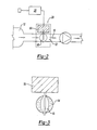
Figure 2 is a schematic view of an example flow control valve. -
Figure 3 is another schematic view of the example flow control valve. - Referring to
Figure 1 , an example of an on-board inert gas generating system (OBIGGS) 10 is shown and includes anair separation module 12 that removes oxygen from manifold bleedairflow 14. Theair separation module 12 removes oxygen from the highpressure air stream 14 and supplies a nitrogen-enrichedair stream 16 to afuel tank 18. Anoxygen stream 22 from theair separation module 12 is exhausted overboard. Theexample fuel tank 18 includes avent 20 to the ambient environment. Thevent 20 causes changes in pressure and temperature within thefuel tank 18 responsive to changes in ambient conditions. - The
system 10 includes aheat exchanger 32 provided to regulate the temperature of the highpressure air stream 14. Theexample heat exchanger 32 exchanges heat between thebleed airflow 14 andram airflow 34 drawn from aram air passage 36. Theram airflow 34 moves at a relatively high flow rate as compared to thebleed airflow 14. The high flow rate of theram airflow 34 is utilized to draw air through theheat exchanger 32 and through theair separation module 12. - An
ejector 38 communicates high pressure airflow 47 to produce a low-pressure region at anoutlet 40 of theair separation module 12. The low-pressure region is produced by the relatively high flow of thehigh pressure airflow 34 at theoutlet 40 and produces the required pressure drop that draws bleedairflow 14 through theair separation module 12. Asecond nozzle 42 produces a low-pressure region adjacent anoutlet 44 of theheat exchange 32. The low pressure produced by the relative high flow of thehigh pressure airflow 34 produces the pressure drop that drives airflow through theheat exchanger 32. The mechanism that drives airflow through theair separation module 12 andheat exchanger 32 is known, and a worker versed in the art would understand that other methods and systems for driving airflow are within the contemplation of this invention. - The quality of the nitrogen-enriched
air stream 16 provided by theair separation module 12 varies given ambient conditions, and a rate of flow. Higher flow rates through theair separation module 12 remove less oxygen relative to lower flow rates. The pressure and temperature within thefuel tank ullage 24 varies responsive to changes in ambient conditions due to communication with ambient conditions through thevent 20. At higher altitudes, the pressure within thefuel tank 18 is at a low level. During descent, ambient pressure, and therefore pressure within thefuel tank 18 increases. The flow rate through theair separation module 12 varies responsive to these changes in ambient conditions affecting the overall amount of oxygen within the nitrogen-enrichedair stream 16 that is provided to thefuel tank ullage 24. - The amount of flow through the
air separation module 12 that produces the optimal, or least amount of oxygen within thefuel tank ullage 24 is determined and controlled by modulating aflow control valve 28. Abackflow prevention valve 29 is provided downstream of theflow control valve 28 to prevent back flow from thefuel tank 18. - A
first sensor 46 provides pressure and temperature information to thecontroller 30. Asecond sensor 25 provides information to thecontroller 30 indicative of conditions within thefuel tank 18. Thecontroller 30 in turn modulates theflow control valve 28 to provide a flow rate of the nitrogen-enrichedair stream 16 through theair separation module 12 that results in the least amount of oxygen within thefuel tank ullage 24. Aninlet pressure sensor 13 and anoutlet pressure sensor 15 provide information on pressure into and out of theair separation module 12. Atemperature sensor 17 provides information on the temperature of thebleed airflow 14. The volume and rate of airflow through theair separation module 12 is limited. Therefore, thecontroller 30 modulates theflow control valve 28 to provide a flow rate through theair separation module 12 that produces the smallest change in oxygen content within thefuel tank ullage 24. - Referring to
Figures 2 and 3 , the exampleflow control valve 28 is shown schematically and includes avalve plate 48 that is rotated by amotor 50. Theexample motor 50 is a torque motor commanded by thecontroller 30. Themotor 50 opens and closes theflow passage 52 to control the nitrogen-enrichedair stream 16. Thevalve plate 48 can be opened and closed to provide a continuouslyvariable opening 54 that provides control over the nitrogen-enrichedair stream 16. Although an exampleflow control valve 28 is described, a worker versed in the art with the benefit of this disclosure that any valve providing for the control of airflow is within the contemplation of this invention. - The
controller 30 can be a commercially available microprocessor as known in the art. A worker versed in the art with the benefit of this disclosure would understand how to program a commercially available microprocessor to command theflow control valve 28. - Referring to
Figure 1 , pressure within thefuel tank ullage 24 changes responsive to ambient pressures. The pressure inside thefuel tank 18 at any given point during descent is substantially equal to ambient pressure. The pressure inside thefuel tank 18 during descent can be represented by the equation:
- Where Win and Wout are flow rates into and out of the
fuel tank 18. Vol is the volume being inerted, y is the ratio of specific heats at constant pressure and constant volume, T is the temperature within thefuel tank ullage 24 in degrees Rankin, and R is the ideal gas constant. During descent air is only flowing into thefuel tank 18 and not exiting. For this reason the change in ullage pressure within thefuel tank 18 is equal to the rate of change in ambient pressure, and is represented by equation 2.
- The
controller 30 utilizes information concerning the change in ambient conditions to determine the proper commands for theflow control valve 28. This is determined by first determining the flow of gas into thefuel tank 18 that produces the ambient pressure. Equation 3 below provides the flow rate of gas into thefuel tank 18 that is required to maintain ambient pressure inside thefuel tank 18.
- The
air separation module 12 is of a limited capacity and cannot under all conditions provide the required flow rate of nitrogen-enrichedair stream 16 that maintains ambient pressure within thefuel tank 18. Accordingly, a portion of the airflow entering thefuel tank 18 will be through thevent 20. Airflow through thevent 20 includes a quantity of oxygen greater than the nitrogen-enrichedair stream 16. - The
example system 10 of this invention minimizes oxygen concentration within thefuel tank ullage 24 by continuously adjusting theflow control valve 28 to provide the optimal airflow through theair separation module 12 that will produce the smallest amount of oxygen content within thefuel tank ullage 24 for the given condition. The change in oxygen concentration in thefuel tank 18 is represented by equation 4 below.
- Where O2tank is oxygen within the fuel tank, Wamb is flow of air through the vent, O2amb is oxygen from flow through the vent, Wnea is the flow of nitrogen-enriched air, and O2nea is the oxygen contained in the nitrogen-enriched air. Substituting equation 3 for total flow, into Equation 4 provides the relationship that provides the amount of oxygen within the
fuel tank 18 for a given pressure and flow. The relationship of oxygen within thefuel tank 18 is provided by Equation 5 below
- Utilizing known relationships between pressure, temperature and flow rates for the
air separation module 12 provides a relationship that represents the amount of oxygen content as related to the rate of the nitrogen-enrichedair stream 16. The relationship is represented by Equation 6 below.
- Where K is a coefficient or group of coefficients relating to operation of the
air separation module 12. Knowledge of oxygen concentration within the nitrogen-enrichedair stream 16 provided by theair separation module 12 combined with knowledge of oxygen content within thefuel tank 18 provides a relationship for oxygen content within thefuel tank 18 related to flow from theair separation module 12. Equation 7 below can represent this relationship.
- The
controller 30 utilizes these relationships to determine a desired flow rate that minimizes changes to the oxygen concentration within thefuel tank 18. The flow rate that provides the minimal changes in oxygen concentration is represented by the relationship shown in Equation 8 below.
- The
controller 30 utilizes this relationship to continually modulate theflow control valve 28 and produce the desired flow rate of nitrogen-enrichedair stream 16 through theair separation module 12 that results in the smallest change in oxygen content within thefuel tank 18. Thecontroller 30 utilizes the relationships shown above to derive the command signal to theflow control valve 28. The flow rate into thefuel tank 18 that provides the current ambient pressure is determined. The flow rate through theair separation module 12 for the current conditions that provides the smallest concentration of oxygen is determined and combined with knowledge of the flow rate into thefuel tank 18 that is required to maintain ambient pressure. Thecontroller 30 then commands theflow control valve 28 to provide the flow that minimizes changes in oxygen concentration within thefuel tank 18. - Once the rate of airflow required to minimize oxygen concentration is known, the
flow control valve 28 is modulated and theopening 54 adjusted. Thecontroller 30 tailors the flow rate of the nitrogen-enrichedair stream 16 responsive to current ambient conditions to minimize oxygen content within thefuel tank 18. Because the nitrogen-enrichedair stream 16 is continuously varied according to current conditions, the capacity of theair separation module 12 is more efficiently utilized. More efficient use of air separation module capacity provides for the use of air separation modules of smaller sizes and capacities. - Although a preferred embodiment of this invention has been disclosed, a worker of ordinary skill in this art would recognize that certain modifications would come within the scope of this invention.
- Also disclosed is a method of controlling oxygen content within a fuel tank ullage, said method comprising the steps of:
- (a) determining a desired flow rate of nitrogen-enriched air required to minimize oxygen content within the fuel tank ullage; and
- (b) controlling an actual flow rate of nitrogen-enriched air responsive to said determination of said desired flow rate of nitrogen-enriched air.
- Step (b) may include modulating a control valve to provide the desired flow rate of nitrogen-enriched air.
- Step (a) may include determining a total flow rate required to maintain a desired pressure within the fuel tank.
- Step (a) may include determining a relationship between oxygen content and a flow rate of nitrogen-enriched air.
- Step (a) may include determining a rate of change in oxygen content within the fuel tank ullage, and determining said desired flow rate of nitrogen-enriched air that minimizes changes to said oxygen content within the fuel tank ullage.
- The method may include the step of continuously reevaluating said desired flow rate of nitrogen-enriched air responsive to ambient conditions.
- The method may further include the step of continuously adjusting the actual flow rate of nitrogen-enriched air based on the reevaluation of said desired flow rate.
- The method may include the step of removing oxygen from an air stream with an air separation module. The method may include generating a low pressure area at a permeate outlet of the air separation module by ejecting high pressure air through an ejector adjacent the permeate outlet of the air separation module.
- The features of the method described above can be correspondingly applied to the apparatus described herein.
- Also disclosed is an on-board inert gas generating system comprising:
- an air separation module receiving an oxygen containing air stream and exhausting a nitrogen-enriched air stream; and
- a flow control valve to control a rate of flow of said nitrogen-enriched air stream exhausted from said air separation module.
- The system may include a controller for adjusting said flow control valve to provide a desired flow rate of said nitrogen-enriched air exhausted from said air separation module.
- Said controller may adjust said flow control valve responsive to a determination of a flow rate required for controlling oxygen content within a fuel tank.
- Said controller may determine a flow rate required for controlling oxygen content within said fuel tank responsive to ambient pressure.
- Said flow control valve may be adjustable to provide an infinitesimal number of flow rates between a minimum and maximum flow rate.
- Said flow control valve may modulate nitrogen-enriched airflow between a maximum flow rate and a minimum flow rate.
- Said controller may determine a flow rate that minimizes changes in oxygen content within a fuel tank ullage and adjusts the flow control valve to provide said flow rate.
- Said controller may determine a capacity of oxygen removal possible from said air separation module responsive to ambient conditions, and adjusts said flow control valve to provide a flow rate that provides a desired oxygen content within said fuel tank ullage.
Claims (13)
- An inert gas generating system comprising:an air separation module (12) for receiving an oxygen containing air stream and exhausting a nitrogen-enriched air stream;a flow control valve (28) to control a rate of flow of the nitrogen-enriched air stream exhausted from the air separation module (12);at least one sensor for measuring pressure and/or temperature; anda controller (30) for adjusting the flow control valve (28) to provide a desired flow rate of the nitrogen-enriched air exhausted from the air separation module (12) based on the pressure and/or temperature measured by the at least one sensor.
- The system as recited in claim 1, wherein the controller (30) adjusts the flow control valve (28) responsive to a determination of a flow rate required for controlling oxygen content within a fuel tank (18).
- The system as recited in claim 2, wherein said controller (30) determines a flow rate required for controlling oxygen content within said fuel tank (18) responsive to ambient pressure.
- The system as recited in any preceding claim, wherein said flow control valve (28) is adjustable to provide an infinitesimal number of flow rates between a minimum and maximum flow rate.
- The system as recited in any preceding claim, wherein said flow control valve (28) modulates nitrogen-enriched airflow between a maximum flow rate and a minimum flow rate.
- The system as recited in any preceding claim, wherein said controller (30) determines a flow rate that minimizes changes in oxygen content within a fuel tank ullage (24) and adjusts the flow control valve (28) to provide the flow rate.
- The system as recited in claim 6, wherein the controller (30) determines a capacity of oxygen removal possible from the air separation module (12) responsive to ambient conditions, and adjusts the flow control valve (28) to provide a flow rate that provides a desired oxygen content within the fuel tank ullage (24) in view of the ambient conditions.
- A fuel tank inerting system comprising:an air separation module (12) for producing a nitrogen-enriched air stream;at least one sensor for measuring ambient conditions;a control valve (28) for controlling the nitrogen enriched air stream from the air separation module (12); anda controller (30) for determining an oxygen concentration within the fuel tank (18) for the measured conditions and a quantity of the nitrogen enriched air stream required to provide a desired oxygen concentration within the fuel tank (18) for the measured ambient conditions and actuating the control valve (28) to provide the desired quantity of nitrogen enriched air.
- The system as recited in claim 8, wherein the controller (30) determines a pressure within the fuel tank (18) based on measured ambient conditions and determines a flow of the nitrogen-enriched air stream required to provide the pressure within the fuel tank (18).
- The system as recited in claim 9, wherein the controller (30) determines a flow rate of the nitrogen enriched air stream that provides a desired concentration of oxygen within the fuel tank (18) and actuates the control valve (28) to provide the desired quantity of nitrogen enriched air.
- The system as recited in claim 8, 9 or 10, including an ejector (38) disposed at an oxygen outlet (40) of the air separation module (12) for generating a desired pressure drop that draws air into the air separation module (12) at a desired flow rate.
- The system as recited in any of claims 8 to 11, including a heat exchanger (32) disposed between a source of oxygen containing air and the air separation module (12).
- The system as recited in any of claims 8 to 12, including a second sensor (25) that provides information to the controller (30) indicative of conditions within a fuel tank (18).
Applications Claiming Priority (2)
| Application Number | Priority Date | Filing Date | Title |
|---|---|---|---|
| US10/901,468 US7509968B2 (en) | 2004-07-28 | 2004-07-28 | Flow control for on-board inert gas generation system |
| EP05770144A EP1771332B1 (en) | 2004-07-28 | 2005-07-19 | Flow control for on-board inert gas generation system |
Related Parent Applications (1)
| Application Number | Title | Priority Date | Filing Date |
|---|---|---|---|
| EP05770144.3 Division | 2005-07-19 |
Publications (3)
| Publication Number | Publication Date |
|---|---|
| EP2332836A2 true EP2332836A2 (en) | 2011-06-15 |
| EP2332836A3 EP2332836A3 (en) | 2011-06-22 |
| EP2332836B1 EP2332836B1 (en) | 2013-06-26 |
Family
ID=34979695
Family Applications (2)
| Application Number | Title | Priority Date | Filing Date |
|---|---|---|---|
| EP05770144A Expired - Lifetime EP1771332B1 (en) | 2004-07-28 | 2005-07-19 | Flow control for on-board inert gas generation system |
| EP20100012368 Expired - Lifetime EP2332836B1 (en) | 2004-07-28 | 2005-07-19 | Flow control for on-board inert gas generation system |
Family Applications Before (1)
| Application Number | Title | Priority Date | Filing Date |
|---|---|---|---|
| EP05770144A Expired - Lifetime EP1771332B1 (en) | 2004-07-28 | 2005-07-19 | Flow control for on-board inert gas generation system |
Country Status (6)
| Country | Link |
|---|---|
| US (2) | US7509968B2 (en) |
| EP (2) | EP1771332B1 (en) |
| JP (1) | JP4531813B2 (en) |
| AT (1) | ATE493337T1 (en) |
| DE (1) | DE602005025639D1 (en) |
| WO (1) | WO2006020286A2 (en) |
Cited By (2)
| Publication number | Priority date | Publication date | Assignee | Title |
|---|---|---|---|---|
| EP2805888A1 (en) * | 2013-05-22 | 2014-11-26 | Hamilton Sundstrand Corporation | Pressure monitoring system for a fuel tank and method |
| WO2017168199A1 (en) * | 2016-03-31 | 2017-10-05 | Behbahani-Pour Mohammed Javad | System, apparatus, and method of preventing fuel tank explosion |
Families Citing this family (66)
| Publication number | Priority date | Publication date | Assignee | Title |
|---|---|---|---|---|
| US7509968B2 (en) * | 2004-07-28 | 2009-03-31 | Hamilton Sundstrand Corporation | Flow control for on-board inert gas generation system |
| DE102004039669A1 (en) * | 2004-08-16 | 2006-03-02 | Airbus Deutschland Gmbh | Air cooling device for aircraft, includes ram-air channel of air generation system heat exchanger, for bleeding cooling air which is utilized for cooling supply air for on-board inert gas generation system |
| US7625434B2 (en) * | 2006-09-12 | 2009-12-01 | Honeywell International Inc. | Enhanced OBIGGS |
| RU2376210C1 (en) * | 2008-06-20 | 2009-12-20 | Открытое акционерное общество "ОКБ Сухого" | System and method for aircraftfuel-tank pressurisation by neutral gas |
| US7828874B2 (en) * | 2008-09-12 | 2010-11-09 | Hamilton Sundstrand Corporation | On-board inert gas generation system with air separation module temperature control |
| US20100155046A1 (en) * | 2008-12-18 | 2010-06-24 | Eric Surawski | Temperature control system for an on board inert gas generation systems |
| US8147579B2 (en) * | 2009-01-12 | 2012-04-03 | Hamilton Sundstrand Corporation | Dispatch critical fuel tank inerting system for aircraft |
| US9033061B2 (en) | 2009-03-23 | 2015-05-19 | Kidde Technologies, Inc. | Fire suppression system and method |
| WO2011005946A1 (en) * | 2009-07-09 | 2011-01-13 | Carleton Life Support Systems Inc. | Thermal conditioning for air separation modules |
| US8074932B2 (en) * | 2009-09-21 | 2011-12-13 | Hamilton Sundstrand Corporation | NEA distribution system for OBIGGS applications |
| JP5427562B2 (en) * | 2009-11-20 | 2014-02-26 | 三菱重工業株式会社 | Aircraft fuel tank having explosion-proof function and explosion-proof method thereof |
| US8313061B2 (en) * | 2009-12-08 | 2012-11-20 | Hamilton Sundstrand Corporation | Inert gas distribution arrangement |
| US20110168164A1 (en) * | 2010-01-08 | 2011-07-14 | Zillmer Andrew J | In situ regolith gas recovery system |
| US8663996B2 (en) | 2010-04-26 | 2014-03-04 | Hamilton Sundstrand Corporation | Determining oxygen concentration in ullage using catalytic oxidation |
| US9044628B2 (en) | 2010-06-16 | 2015-06-02 | Kidde Technologies, Inc. | Fire suppression system |
| US20110308823A1 (en) * | 2010-06-17 | 2011-12-22 | Dharmendr Len Seebaluck | Programmable controller for a fire prevention system |
| CN103328050A (en) * | 2010-10-12 | 2013-09-25 | 派克汉尼芬公司 | Fuel tank flammability-reducing gas distribution architecture |
| BR112013009852A2 (en) * | 2010-10-22 | 2016-11-22 | Kenneth Susko | optical probe containing oxygen, temperature, and pressure sensors and monitoring and control systems containing them |
| US9298193B2 (en) * | 2010-10-22 | 2016-03-29 | Kenneth Susko | Optical probe containing oxygen, temperature, and pressure sensors and monitoring and control systems containing the same |
| GB201101463D0 (en) * | 2011-01-28 | 2011-03-16 | Airbus Operations Ltd | Aircraft fuel system |
| US8499567B2 (en) * | 2011-06-27 | 2013-08-06 | Honeywell International, Inc. | Hybrid fuel tank inerting system |
| US8925642B2 (en) * | 2011-06-29 | 2015-01-06 | The Boeing Company | Scalable cargo fire-suppression agent distribution system |
| FR2979136B1 (en) * | 2011-08-16 | 2014-11-14 | Snecma | DEVICE FOR ACTIVATING A PASSIVE EJECTOR VALVE FOR PRESSURIZING AN AIRCRAFT TURBOEER SPEAKER |
| US8801831B1 (en) * | 2011-12-13 | 2014-08-12 | The Boeing Company | Fuel saving inert gas generation system |
| US8778062B1 (en) * | 2011-12-15 | 2014-07-15 | The Boeing Company | Warming system for air separation modules |
| GB201204959D0 (en) * | 2012-03-21 | 2012-05-02 | Airbus Operations Ltd | Conditioning system for fuel cell exhaust |
| GB2501733A (en) * | 2012-05-02 | 2013-11-06 | Eaton Aerospace Ltd | Aircraft fuel tank inerting system |
| US9550575B2 (en) | 2012-05-25 | 2017-01-24 | B/E Aerospace, Inc. | On-board generation of oxygen for aircraft pilots |
| US9120571B2 (en) | 2012-05-25 | 2015-09-01 | B/E Aerospace, Inc. | Hybrid on-board generation of oxygen for aircraft passengers |
| US9550570B2 (en) | 2012-05-25 | 2017-01-24 | B/E Aerospace, Inc. | On-board generation of oxygen for aircraft passengers |
| US9758255B1 (en) * | 2012-06-22 | 2017-09-12 | Kps, Llc | Methods and systems for controlling flammability risk in aircraft fuel tanks |
| US9027885B2 (en) | 2012-09-27 | 2015-05-12 | Hamilton Sundstrand Corporation | Nitrogen gas system with diverter valve |
| JP6086701B2 (en) | 2012-11-09 | 2017-03-01 | 三菱航空機株式会社 | Nitrogen-enriched gas supply system, aircraft |
| GB201303527D0 (en) | 2013-02-28 | 2013-04-10 | Airbus Uk Ltd | Aircraft inerting system |
| US9421406B2 (en) * | 2013-08-05 | 2016-08-23 | Kidde Technologies, Inc. | Freighter cargo fire protection |
| US9302778B2 (en) | 2013-08-07 | 2016-04-05 | Hamilton Sundstrand Corporation | Dual heat exchanger fuel tank inerting system |
| FR3012421B1 (en) * | 2013-10-31 | 2016-12-09 | Intertechnique Sa | METHOD AND DEVICE FOR INERTING A FUEL TANK |
| GB2520728A (en) * | 2013-11-29 | 2015-06-03 | Airbus Operations Ltd | Aircraft fuel tank inerting arrangement |
| US10610712B2 (en) * | 2013-12-02 | 2020-04-07 | Aero Systems Consultants LLC | Aircraft fuel systems |
| GB2533584A (en) * | 2014-12-22 | 2016-06-29 | Airbus Operations Ltd | Aircraft fuel tank inerting arrangement, method of inerting one or more aircraft fuel tanks, aircraft and software product |
| US9505500B2 (en) * | 2015-01-23 | 2016-11-29 | Ametek, Inc. | Inerting fuel systems, methods, and apparatuses |
| US10137406B2 (en) | 2015-06-11 | 2018-11-27 | Hamilton Sundstrand Corporation | Temperature controlled nitrogen generation system |
| US10344673B2 (en) | 2016-06-27 | 2019-07-09 | General Electric Company | System and method of cooling a turbine engine |
| FR3054795B1 (en) * | 2016-08-03 | 2018-07-20 | Zodiac Aerotechnics | METHOD AND SYSTEM FOR INERTING A FUEL TANK |
| FR3054965B1 (en) | 2016-08-12 | 2018-07-27 | Zodiac Aerotechnics | METHOD FOR CONTROLLING AN INTEGRATION SYSTEM OF A FUEL TANK, AND INERT SYSTEM FOR IMPLEMENTING THE PROCESS |
| US10648382B2 (en) * | 2016-10-05 | 2020-05-12 | Parker-Hannifin Corporation | Inerting and venting system |
| FR3058391B1 (en) * | 2016-11-08 | 2018-11-30 | Zodiac Aerotechnics | PROCESS FOR CONTROLLING THE PURITY TORQUE / FLOW OF AN INERT GAS INJECTED IN A FUEL TANK, INTEGRATION SYSTEM FOR IMPLEMENTING THE PROCESS |
| US10472083B2 (en) * | 2016-12-14 | 2019-11-12 | Hamilton Sundstrand Corporation | Selective method of operation of ullage passivation system |
| US11376458B2 (en) | 2016-12-20 | 2022-07-05 | Carrier Corporation | Fire protection system for an enclosure and method of fire protection for an enclosure |
| US10286235B2 (en) * | 2017-02-22 | 2019-05-14 | The Boeing Company | Systems and methods for flammability reduction and ventilation using nitrogen-enriched gas for transportation vehicle protection |
| EP3417914B1 (en) * | 2017-06-22 | 2022-07-27 | Kidde Graviner Limited | Fire suppression systems |
| GB2576951A (en) | 2018-09-10 | 2020-03-11 | Airbus Operations Ltd | Aircraft fuel tank inerting |
| US10994894B2 (en) * | 2018-11-27 | 2021-05-04 | Bauer Compressors, Inc. | Liquid storage tank protection system and method |
| US11155359B2 (en) | 2019-09-19 | 2021-10-26 | Embraer S.A. | Aircraft fuel tank pressurization systems and methods |
| CN111071465A (en) * | 2020-01-06 | 2020-04-28 | 南京航空航天大学 | A low-temperature freezing nitrogen-making fuel tank inerting system and its working method |
| CN111114803A (en) * | 2020-01-06 | 2020-05-08 | 南京航空航天大学 | A system for improving the separation efficiency of airborne hollow fiber membranes and its working method |
| US12172758B2 (en) | 2020-10-13 | 2024-12-24 | General Electric Company | System and method for cooling aircraft components |
| US11485499B2 (en) | 2020-10-13 | 2022-11-01 | General Electric Company | System and method for cooling aircraft components |
| CN112435091B (en) * | 2020-11-23 | 2024-03-29 | 百果园技术(新加坡)有限公司 | Recommended content selection method, device, equipment and storage medium |
| US12553626B2 (en) | 2022-06-29 | 2026-02-17 | Rescue Air Systems, Inc. | System and method of a loop architecture of a fixed piping system implemented within a safety system of a structure to continuously supply breathable air therewithin |
| US12605572B2 (en) | 2022-06-29 | 2026-04-21 | Rescue Air Systems, Inc. | Method and system of automatically modifying a rate of filling an air bottle with breathable air in a firefighter air replenishment system based on flow rate detection thereof |
| AU2023299112A1 (en) | 2022-06-29 | 2024-10-31 | Rescue Air Systems, Inc. | Methods and system of incident based camera device activation in a firefighter air replenishment system having breathable air supplied therein |
| US12315317B2 (en) | 2022-06-29 | 2025-05-27 | Rescue Air Systems, Inc. | Method and system of sensor-based smart unlocking of a firefighter air replenishment system |
| US12544601B2 (en) | 2022-06-29 | 2026-02-10 | Rescue Air Systems, Inc. | System and method of a ring architecture of a fixed piping system implemented within a safety system of a structure to continuously supply breathable air therewithin |
| GB2622644B (en) | 2022-09-26 | 2025-04-30 | Airbus Operations Ltd | Controlling aircraft inerting system |
| CN116477062B (en) * | 2022-12-29 | 2026-01-16 | 中国航空工业集团公司金城南京机电液压工程研究中心 | An adaptively adjustable electric drive inerting system and its adjustment method |
Family Cites Families (28)
| Publication number | Priority date | Publication date | Assignee | Title |
|---|---|---|---|---|
| US3847298A (en) * | 1972-03-20 | 1974-11-12 | Garrett Corp | Fuel tank inerting system |
| US4556180A (en) * | 1978-12-07 | 1985-12-03 | The Garrett Corporation | Fuel tank inerting system |
| US4378920A (en) * | 1980-07-15 | 1983-04-05 | The Boeing Company | Combustibly inert air supply system and method |
| US4681602A (en) * | 1984-12-24 | 1987-07-21 | The Boeing Company | Integrated system for generating inert gas and breathing gas on aircraft |
| DE3541263A1 (en) * | 1985-11-22 | 1987-05-27 | Daimler Benz Ag | AIR CONDITIONING FOR VEHICLES |
| US4840064A (en) * | 1988-03-15 | 1989-06-20 | Sundstrand Corp. | Liquid volume monitoring apparatus and method |
| US5069692A (en) * | 1989-12-11 | 1991-12-03 | Sundstrand Corporation | Fully integrated inert gas and oxidizer replenishment system |
| US5131225A (en) * | 1990-08-31 | 1992-07-21 | Sundstrand Corporation | Apparatus for separating and compressing oxygen from an air stream |
| US6314754B1 (en) * | 2000-04-17 | 2001-11-13 | Igor K. Kotliar | Hypoxic fire prevention and fire suppression systems for computer rooms and other human occupied facilities |
| US8245978B1 (en) | 1998-06-30 | 2012-08-21 | L'air Liquide Societe Anonyme Pour L'etude Et L'exploitation Des Procedes Georges Claude | Multiple ASM OBIGGS with different permeability and selectivity membranes |
| JP2003530922A (en) * | 2000-04-17 | 2003-10-21 | コトライアー・イガー・ケイ | Low Oxygen Concentration Fire Prevention and Fire Suppression Systems and Respirable Fire Extinguishing Compositions in Manned Environments |
| US6502421B2 (en) * | 2000-12-28 | 2003-01-07 | Igor K. Kotliar | Mobile firefighting systems with breathable hypoxic fire extinguishing compositions for human occupied environments |
| US6557374B2 (en) * | 2000-12-28 | 2003-05-06 | Igor K. Kotliar | Tunnel fire suppression system and methods for selective delivery of breathable fire suppressant directly to fire site |
| US6560991B1 (en) * | 2000-12-28 | 2003-05-13 | Kotliar Igor K | Hyperbaric hypoxic fire escape and suppression systems for multilevel buildings, transportation tunnels and other human-occupied environments |
| JP4538899B2 (en) * | 2000-05-31 | 2010-09-08 | 株式会社島津製作所 | Explosion-proof device for fuel supply |
| US6585192B2 (en) * | 2000-12-21 | 2003-07-01 | L'air Liquide - Societe Anonyme A'directoire Et Conseil De Surveillance Pour L'etude Et L'exploitation Des Procedes Georges Claude | Vented compartment inerting system |
| WO2002028714A1 (en) | 2000-10-02 | 2002-04-11 | L'air Liquide, Society Anonyme Pour L'etude Et L'exploitation Des Procedes Georges Claude | Aircraft fuel tank inerting |
| FR2824045B1 (en) * | 2001-04-26 | 2003-07-25 | Air Liquide | METHOD AND DEVICE FOR INERTING AN AIRCRAFT FUEL TANK |
| US6634598B2 (en) * | 2001-11-28 | 2003-10-21 | Kenneth Susko | On-board fuel inerting system |
| JP4039107B2 (en) * | 2002-04-26 | 2008-01-30 | 株式会社島津製作所 | Air conditioner for aircraft |
| US6729359B2 (en) * | 2002-06-28 | 2004-05-04 | Shaw Aero Devices, Inc. | Modular on-board inert gas generating system |
| US6739359B2 (en) * | 2002-10-04 | 2004-05-25 | Shaw Aero Devices, Inc. | On-board inert gas generating system optimization by pressure scheduling |
| US7048231B2 (en) * | 2002-10-04 | 2006-05-23 | Shaw Aero Devices, Inc. | Increasing the performance of aircraft on-board inert gas generating systems by turbocharging |
| US6913636B2 (en) * | 2002-12-17 | 2005-07-05 | Hamilton Sundstrand Corporation | Low power nitrogen enriched air generation system |
| FR2855812B1 (en) * | 2003-06-05 | 2005-07-22 | Air Liquide | ONBOARD SYSTEM FOR THE GENERATION AND SUPPLY OF OXYGEN AND NITROGEN |
| US7081153B2 (en) * | 2003-12-02 | 2006-07-25 | Honeywell International Inc. | Gas generating system and method for inerting aircraft fuel tanks |
| US7013905B2 (en) * | 2004-04-14 | 2006-03-21 | Shaw Aero Devices, Inc. | System and method for monitoring the performance of an inert gas distribution system |
| US7509968B2 (en) * | 2004-07-28 | 2009-03-31 | Hamilton Sundstrand Corporation | Flow control for on-board inert gas generation system |
-
2004
- 2004-07-28 US US10/901,468 patent/US7509968B2/en not_active Expired - Lifetime
-
2005
- 2005-07-19 EP EP05770144A patent/EP1771332B1/en not_active Expired - Lifetime
- 2005-07-19 EP EP20100012368 patent/EP2332836B1/en not_active Expired - Lifetime
- 2005-07-19 WO PCT/US2005/025565 patent/WO2006020286A2/en not_active Ceased
- 2005-07-19 JP JP2007523637A patent/JP4531813B2/en not_active Expired - Fee Related
- 2005-07-19 DE DE602005025639T patent/DE602005025639D1/en not_active Expired - Lifetime
- 2005-07-19 AT AT05770144T patent/ATE493337T1/en not_active IP Right Cessation
-
2008
- 2008-11-25 US US12/277,513 patent/US7921869B2/en not_active Expired - Lifetime
Non-Patent Citations (1)
| Title |
|---|
| None |
Cited By (5)
| Publication number | Priority date | Publication date | Assignee | Title |
|---|---|---|---|---|
| EP2805888A1 (en) * | 2013-05-22 | 2014-11-26 | Hamilton Sundstrand Corporation | Pressure monitoring system for a fuel tank and method |
| WO2017168199A1 (en) * | 2016-03-31 | 2017-10-05 | Behbahani-Pour Mohammed Javad | System, apparatus, and method of preventing fuel tank explosion |
| GB2568392A (en) * | 2016-03-31 | 2019-05-15 | Mohammed Javad Behbahani Pour | System, apparatus, and method of preventing fuel tank explosion |
| US10858118B2 (en) | 2016-03-31 | 2020-12-08 | Mohammed Javad Behbahani-Pour | System, apparatus, and method of preventing fuel tank explosion |
| GB2568392B (en) * | 2016-03-31 | 2020-12-16 | Mohammed Javad Behbahani Pour | System, apparatus, and method of preventing fuel tank explosion |
Also Published As
| Publication number | Publication date |
|---|---|
| EP2332836B1 (en) | 2013-06-26 |
| JP4531813B2 (en) | 2010-08-25 |
| US20060021652A1 (en) | 2006-02-02 |
| US20090071340A1 (en) | 2009-03-19 |
| ATE493337T1 (en) | 2011-01-15 |
| US7509968B2 (en) | 2009-03-31 |
| DE602005025639D1 (en) | 2011-02-10 |
| WO2006020286A2 (en) | 2006-02-23 |
| US7921869B2 (en) | 2011-04-12 |
| EP1771332B1 (en) | 2010-12-29 |
| EP2332836A3 (en) | 2011-06-22 |
| EP1771332A2 (en) | 2007-04-11 |
| JP2008508136A (en) | 2008-03-21 |
| WO2006020286A3 (en) | 2006-05-11 |
Similar Documents
| Publication | Publication Date | Title |
|---|---|---|
| EP2332836B1 (en) | Flow control for on-board inert gas generation system | |
| US6547188B2 (en) | Process and device for inerting an aircraft fuel tank | |
| EP2772436B1 (en) | Aircraft inerting system | |
| EP1108458B1 (en) | Air separation module using a fast start valve for fast warm up of the permeable membrane | |
| US7608131B2 (en) | Three flow architecture and method for aircraft OBIGGS | |
| US7374601B2 (en) | Air separation system and method with modulated warning flow | |
| US7445659B2 (en) | Ejector to reduce permeate backpressure of air separation module | |
| US8171932B2 (en) | Oxygen breathing device for an aircraft | |
| US7152635B2 (en) | Commercial aircraft on-board inerting system | |
| EP3103544B1 (en) | Temperature controlled nitrogen generation system and method of generating nitrogen-enriched air | |
| US11584536B2 (en) | Method and device for inerting a fuel tank | |
| WO2005002968A1 (en) | On-board inert gas generating system | |
| WO2004002826A1 (en) | Modular on-board inert gas generating system | |
| EP1765444B1 (en) | Demand and dilution mask regulator and method of regulating additional oxygen in the mask regulator | |
| US10213630B2 (en) | Method for the control of the breathing gas supply | |
| US11472566B2 (en) | Catalyst decay monitoring of catalytic inerting system | |
| CA2086879A1 (en) | Process and apparatus for delivering a metered shot | |
| US9963239B2 (en) | Nitrogen enriched air supply system and aircraft | |
| EP4309765A1 (en) | Improvements in or relating to gas apparatus | |
| US11155358B2 (en) | Catalytic fuel tank inerting systems for aircraft | |
| EP3492382A1 (en) | Air-conditioning system for an aircraft | |
| KR101826586B1 (en) | Pressure controlling system for fuel tank of flight | |
| JP4203705B2 (en) | Aircraft explosion-proof system | |
| DE102023122071A1 (en) | Fuel cell system, method for operating it and a motor vehicle comprising the fuel cell system | |
| CN110732215B (en) | Recovery system and method for tail gas of vacuum condensate tank |
Legal Events
| Date | Code | Title | Description |
|---|---|---|---|
| PUAI | Public reference made under article 153(3) epc to a published international application that has entered the european phase |
Free format text: ORIGINAL CODE: 0009012 |
|
| PUAL | Search report despatched |
Free format text: ORIGINAL CODE: 0009013 |
|
| AC | Divisional application: reference to earlier application |
Ref document number: 1771332 Country of ref document: EP Kind code of ref document: P |
|
| AK | Designated contracting states |
Kind code of ref document: A2 Designated state(s): AT BE BG CH CY CZ DE DK EE ES FI FR GB GR HU IE IS IT LI LT LU LV MC NL PL PT RO SE SI SK TR |
|
| AK | Designated contracting states |
Kind code of ref document: A3 Designated state(s): AT BE BG CH CY CZ DE DK EE ES FI FR GB GR HU IE IS IT LI LT LU LV MC NL PL PT RO SE SI SK TR |
|
| 17P | Request for examination filed |
Effective date: 20111115 |
|
| 17Q | First examination report despatched |
Effective date: 20120416 |
|
| GRAP | Despatch of communication of intention to grant a patent |
Free format text: ORIGINAL CODE: EPIDOSNIGR1 |
|
| GRAS | Grant fee paid |
Free format text: ORIGINAL CODE: EPIDOSNIGR3 |
|
| GRAA | (expected) grant |
Free format text: ORIGINAL CODE: 0009210 |
|
| AC | Divisional application: reference to earlier application |
Ref document number: 1771332 Country of ref document: EP Kind code of ref document: P |
|
| AK | Designated contracting states |
Kind code of ref document: B1 Designated state(s): AT BE BG CH CY CZ DE DK EE ES FI FR GB GR HU IE IS IT LI LT LU LV MC NL PL PT RO SE SI SK TR |
|
| REG | Reference to a national code |
Ref country code: GB Ref legal event code: FG4D |
|
| REG | Reference to a national code |
Ref country code: CH Ref legal event code: EP |
|
| REG | Reference to a national code |
Ref country code: AT Ref legal event code: REF Ref document number: 618576 Country of ref document: AT Kind code of ref document: T Effective date: 20130715 |
|
| REG | Reference to a national code |
Ref country code: IE Ref legal event code: FG4D |
|
| REG | Reference to a national code |
Ref country code: DE Ref legal event code: R096 Ref document number: 602005040201 Country of ref document: DE Effective date: 20130822 |
|
| PG25 | Lapsed in a contracting state [announced via postgrant information from national office to epo] |
Ref country code: LT Free format text: LAPSE BECAUSE OF FAILURE TO SUBMIT A TRANSLATION OF THE DESCRIPTION OR TO PAY THE FEE WITHIN THE PRESCRIBED TIME-LIMIT Effective date: 20130626 Ref country code: SE Free format text: LAPSE BECAUSE OF FAILURE TO SUBMIT A TRANSLATION OF THE DESCRIPTION OR TO PAY THE FEE WITHIN THE PRESCRIBED TIME-LIMIT Effective date: 20130626 Ref country code: GR Free format text: LAPSE BECAUSE OF FAILURE TO SUBMIT A TRANSLATION OF THE DESCRIPTION OR TO PAY THE FEE WITHIN THE PRESCRIBED TIME-LIMIT Effective date: 20130927 Ref country code: FI Free format text: LAPSE BECAUSE OF FAILURE TO SUBMIT A TRANSLATION OF THE DESCRIPTION OR TO PAY THE FEE WITHIN THE PRESCRIBED TIME-LIMIT Effective date: 20130626 Ref country code: SI Free format text: LAPSE BECAUSE OF FAILURE TO SUBMIT A TRANSLATION OF THE DESCRIPTION OR TO PAY THE FEE WITHIN THE PRESCRIBED TIME-LIMIT Effective date: 20130626 |
|
| REG | Reference to a national code |
Ref country code: AT Ref legal event code: MK05 Ref document number: 618576 Country of ref document: AT Kind code of ref document: T Effective date: 20130626 |
|
| REG | Reference to a national code |
Ref country code: LT Ref legal event code: MG4D |
|
| PG25 | Lapsed in a contracting state [announced via postgrant information from national office to epo] |
Ref country code: BG Free format text: LAPSE BECAUSE OF FAILURE TO SUBMIT A TRANSLATION OF THE DESCRIPTION OR TO PAY THE FEE WITHIN THE PRESCRIBED TIME-LIMIT Effective date: 20130926 |
|
| REG | Reference to a national code |
Ref country code: NL Ref legal event code: VDEP Effective date: 20130626 |
|
| PG25 | Lapsed in a contracting state [announced via postgrant information from national office to epo] |
Ref country code: LV Free format text: LAPSE BECAUSE OF FAILURE TO SUBMIT A TRANSLATION OF THE DESCRIPTION OR TO PAY THE FEE WITHIN THE PRESCRIBED TIME-LIMIT Effective date: 20130626 |
|
| PG25 | Lapsed in a contracting state [announced via postgrant information from national office to epo] |
Ref country code: BE Free format text: LAPSE BECAUSE OF FAILURE TO SUBMIT A TRANSLATION OF THE DESCRIPTION OR TO PAY THE FEE WITHIN THE PRESCRIBED TIME-LIMIT Effective date: 20130626 Ref country code: SK Free format text: LAPSE BECAUSE OF FAILURE TO SUBMIT A TRANSLATION OF THE DESCRIPTION OR TO PAY THE FEE WITHIN THE PRESCRIBED TIME-LIMIT Effective date: 20130626 Ref country code: IS Free format text: LAPSE BECAUSE OF FAILURE TO SUBMIT A TRANSLATION OF THE DESCRIPTION OR TO PAY THE FEE WITHIN THE PRESCRIBED TIME-LIMIT Effective date: 20131026 Ref country code: EE Free format text: LAPSE BECAUSE OF FAILURE TO SUBMIT A TRANSLATION OF THE DESCRIPTION OR TO PAY THE FEE WITHIN THE PRESCRIBED TIME-LIMIT Effective date: 20130626 Ref country code: PT Free format text: LAPSE BECAUSE OF FAILURE TO SUBMIT A TRANSLATION OF THE DESCRIPTION OR TO PAY THE FEE WITHIN THE PRESCRIBED TIME-LIMIT Effective date: 20131028 Ref country code: CZ Free format text: LAPSE BECAUSE OF FAILURE TO SUBMIT A TRANSLATION OF THE DESCRIPTION OR TO PAY THE FEE WITHIN THE PRESCRIBED TIME-LIMIT Effective date: 20130626 Ref country code: AT Free format text: LAPSE BECAUSE OF FAILURE TO SUBMIT A TRANSLATION OF THE DESCRIPTION OR TO PAY THE FEE WITHIN THE PRESCRIBED TIME-LIMIT Effective date: 20130626 Ref country code: CY Free format text: LAPSE BECAUSE OF FAILURE TO SUBMIT A TRANSLATION OF THE DESCRIPTION OR TO PAY THE FEE WITHIN THE PRESCRIBED TIME-LIMIT Effective date: 20130724 |
|
| PG25 | Lapsed in a contracting state [announced via postgrant information from national office to epo] |
Ref country code: NL Free format text: LAPSE BECAUSE OF FAILURE TO SUBMIT A TRANSLATION OF THE DESCRIPTION OR TO PAY THE FEE WITHIN THE PRESCRIBED TIME-LIMIT Effective date: 20130626 Ref country code: RO Free format text: LAPSE BECAUSE OF FAILURE TO SUBMIT A TRANSLATION OF THE DESCRIPTION OR TO PAY THE FEE WITHIN THE PRESCRIBED TIME-LIMIT Effective date: 20130626 Ref country code: PL Free format text: LAPSE BECAUSE OF FAILURE TO SUBMIT A TRANSLATION OF THE DESCRIPTION OR TO PAY THE FEE WITHIN THE PRESCRIBED TIME-LIMIT Effective date: 20130626 Ref country code: ES Free format text: LAPSE BECAUSE OF FAILURE TO SUBMIT A TRANSLATION OF THE DESCRIPTION OR TO PAY THE FEE WITHIN THE PRESCRIBED TIME-LIMIT Effective date: 20131007 |
|
| REG | Reference to a national code |
Ref country code: CH Ref legal event code: PL |
|
| PG25 | Lapsed in a contracting state [announced via postgrant information from national office to epo] |
Ref country code: MC Free format text: LAPSE BECAUSE OF FAILURE TO SUBMIT A TRANSLATION OF THE DESCRIPTION OR TO PAY THE FEE WITHIN THE PRESCRIBED TIME-LIMIT Effective date: 20130626 Ref country code: CY Free format text: LAPSE BECAUSE OF FAILURE TO SUBMIT A TRANSLATION OF THE DESCRIPTION OR TO PAY THE FEE WITHIN THE PRESCRIBED TIME-LIMIT Effective date: 20130626 |
|
| REG | Reference to a national code |
Ref country code: IE Ref legal event code: MM4A |
|
| PG25 | Lapsed in a contracting state [announced via postgrant information from national office to epo] |
Ref country code: LI Free format text: LAPSE BECAUSE OF NON-PAYMENT OF DUE FEES Effective date: 20130731 Ref country code: CH Free format text: LAPSE BECAUSE OF NON-PAYMENT OF DUE FEES Effective date: 20130731 Ref country code: DK Free format text: LAPSE BECAUSE OF FAILURE TO SUBMIT A TRANSLATION OF THE DESCRIPTION OR TO PAY THE FEE WITHIN THE PRESCRIBED TIME-LIMIT Effective date: 20130626 |
|
| PLBE | No opposition filed within time limit |
Free format text: ORIGINAL CODE: 0009261 |
|
| STAA | Information on the status of an ep patent application or granted ep patent |
Free format text: STATUS: NO OPPOSITION FILED WITHIN TIME LIMIT |
|
| 26N | No opposition filed |
Effective date: 20140327 |
|
| REG | Reference to a national code |
Ref country code: DE Ref legal event code: R097 Ref document number: 602005040201 Country of ref document: DE Effective date: 20140327 |
|
| PG25 | Lapsed in a contracting state [announced via postgrant information from national office to epo] |
Ref country code: IE Free format text: LAPSE BECAUSE OF NON-PAYMENT OF DUE FEES Effective date: 20130719 |
|
| PG25 | Lapsed in a contracting state [announced via postgrant information from national office to epo] |
Ref country code: TR Free format text: LAPSE BECAUSE OF FAILURE TO SUBMIT A TRANSLATION OF THE DESCRIPTION OR TO PAY THE FEE WITHIN THE PRESCRIBED TIME-LIMIT Effective date: 20130626 |
|
| PG25 | Lapsed in a contracting state [announced via postgrant information from national office to epo] |
Ref country code: HU Free format text: LAPSE BECAUSE OF FAILURE TO SUBMIT A TRANSLATION OF THE DESCRIPTION OR TO PAY THE FEE WITHIN THE PRESCRIBED TIME-LIMIT; INVALID AB INITIO Effective date: 20050719 Ref country code: LU Free format text: LAPSE BECAUSE OF NON-PAYMENT OF DUE FEES Effective date: 20130719 |
|
| REG | Reference to a national code |
Ref country code: FR Ref legal event code: PLFP Year of fee payment: 12 |
|
| REG | Reference to a national code |
Ref country code: FR Ref legal event code: PLFP Year of fee payment: 13 |
|
| REG | Reference to a national code |
Ref country code: DE Ref legal event code: R082 Ref document number: 602005040201 Country of ref document: DE Representative=s name: SCHMITT-NILSON SCHRAUD WAIBEL WOHLFROM PATENTA, DE |
|
| REG | Reference to a national code |
Ref country code: FR Ref legal event code: PLFP Year of fee payment: 14 |
|
| P01 | Opt-out of the competence of the unified patent court (upc) registered |
Effective date: 20230522 |
|
| PGFP | Annual fee paid to national office [announced via postgrant information from national office to epo] |
Ref country code: GB Payment date: 20240620 Year of fee payment: 20 |
|
| PGFP | Annual fee paid to national office [announced via postgrant information from national office to epo] |
Ref country code: FR Payment date: 20240619 Year of fee payment: 20 |
|
| PGFP | Annual fee paid to national office [announced via postgrant information from national office to epo] |
Ref country code: IT Payment date: 20240619 Year of fee payment: 20 |
|
| PGFP | Annual fee paid to national office [announced via postgrant information from national office to epo] |
Ref country code: DE Payment date: 20240619 Year of fee payment: 20 |
|
| REG | Reference to a national code |
Ref country code: DE Ref legal event code: R071 Ref document number: 602005040201 Country of ref document: DE |
|
| REG | Reference to a national code |
Ref country code: GB Ref legal event code: PE20 Expiry date: 20250718 |