EP2332835A2 - Single plane mount system for gas turbine engine - Google Patents
Single plane mount system for gas turbine engine Download PDFInfo
- Publication number
- EP2332835A2 EP2332835A2 EP10252040A EP10252040A EP2332835A2 EP 2332835 A2 EP2332835 A2 EP 2332835A2 EP 10252040 A EP10252040 A EP 10252040A EP 10252040 A EP10252040 A EP 10252040A EP 2332835 A2 EP2332835 A2 EP 2332835A2
- Authority
- EP
- European Patent Office
- Prior art keywords
- gas turbine
- link
- turbine engine
- support structure
- plane
- Prior art date
- Legal status (The legal status is an assumption and is not a legal conclusion. Google has not performed a legal analysis and makes no representation as to the accuracy of the status listed.)
- Granted
Links
Images


Classifications
-
- B—PERFORMING OPERATIONS; TRANSPORTING
- B64—AIRCRAFT; AVIATION; COSMONAUTICS
- B64D—EQUIPMENT FOR FITTING IN OR TO AIRCRAFT; FLIGHT SUITS; PARACHUTES; ARRANGEMENT OR MOUNTING OF POWER PLANTS OR PROPULSION TRANSMISSIONS IN AIRCRAFT
- B64D27/00—Arrangement or mounting of power plants in aircraft; Aircraft characterised by the type or position of power plants
- B64D27/02—Aircraft characterised by the type or position of power plants
- B64D27/16—Aircraft characterised by the type or position of power plants of jet type
- B64D27/20—Aircraft characterised by the type or position of power plants of jet type within, or attached to, fuselages
-
- B—PERFORMING OPERATIONS; TRANSPORTING
- B64—AIRCRAFT; AVIATION; COSMONAUTICS
- B64D—EQUIPMENT FOR FITTING IN OR TO AIRCRAFT; FLIGHT SUITS; PARACHUTES; ARRANGEMENT OR MOUNTING OF POWER PLANTS OR PROPULSION TRANSMISSIONS IN AIRCRAFT
- B64D27/00—Arrangement or mounting of power plants in aircraft; Aircraft characterised by the type or position of power plants
- B64D27/40—Arrangements for mounting power plants in aircraft
- B64D27/406—Suspension arrangements specially adapted for supporting thrust loads, e.g. thrust links
-
- Y—GENERAL TAGGING OF NEW TECHNOLOGICAL DEVELOPMENTS; GENERAL TAGGING OF CROSS-SECTIONAL TECHNOLOGIES SPANNING OVER SEVERAL SECTIONS OF THE IPC; TECHNICAL SUBJECTS COVERED BY FORMER USPC CROSS-REFERENCE ART COLLECTIONS [XRACs] AND DIGESTS
- Y02—TECHNOLOGIES OR APPLICATIONS FOR MITIGATION OR ADAPTATION AGAINST CLIMATE CHANGE
- Y02T—CLIMATE CHANGE MITIGATION TECHNOLOGIES RELATED TO TRANSPORTATION
- Y02T50/00—Aeronautics or air transport
- Y02T50/40—Weight reduction
Definitions
- This disclosure generally relates to a mounting system and arrangement a gas turbine engine. More particularly, this disclosure relates to a mounting system and arrangement that reduces bending loads on the gas turbine engine.
- a mounting system for a gas turbine engine provides for the transfer of engine thrust to an airframe.
- the same mounting system can also transfer air and maneuver loads onto the gas turbine engine during operation.
- the application of loads on the gas turbine engine can cause deflection of engine components.
- Conventional engine mounting systems include several connections points between a pylon of the aircraft and the gas turbine engine. The several different mounting points further transmit air and maneuver loads encountered by the aircraft to the gas turbine engine. It is desirable to limit the transference of external loads onto the gas turbine engines.
- a mounting system for a gas turbine engine assembly includes a plurality of mounting links attached the gas turbine engine along a single plane transverse to the engine centerline.
- the disclosed mounting system includes an outer link assembly, an upper thrust link, and lower thrust links all attached to the engine within the single plane.
- Each of the links further is attached to a support structure mounted to an airframe section.
- the mounting system supports the gas turbine engine along the single plane to separate loads from the core engine.
- a mounting system for a gas turbine engine assembly 10 includes an outer link assembly 34, an upper thrust link 36 and first and second thrust links 38A and 38B (only 38A shown here) that are attached to the gas turbine engine 10 along a single plane 46 to a support structure 14 mounted to an airframe section 16.
- the example gas turbine engine assembly 10 includes a core engine 18 centered along an axis 48 that drives a fan 20 for generating a desired amount of thrust T.
- the example support structure 14 is a portion of a pylon mounted to a wing of an aircraft; however, the other engine mounting locations and structures are within the contemplation of this disclosure.
- the example core engine 18 includes a compressor section 28 that feeds incoming air to a combustor section 30. Fuel is mixed with the incoming air and ignited in the combustor section 30 to produce a flow of gases that drives the turbine section 32. The turbine section 32 in turn drives the compressor section 28 and the fan 20. An outer nacelle 12 surrounds the fan 20 and directs airflow into the core engine 18.
- the mounting system transfer thrust T to the airframe section 16 and is vertically, laterally, and torsionally stiff to withstand engine torque and maneuver loads while providing for airflow through the engine assembly 10.
- larger sizes of fans 20 necessarily require larger opening nacelle section 12 that in turn increases air loading L during takeoff and other high angle of attack maneuvers.
- the disclosed mounting systems supports the gas turbine engine along the single plane 46 to separate the air loads L and other maneuver loads from the core engine 18. The separation of the air loads L and maneuver loads reduces bending stress on the core engine 18.
- the gas turbine engine assembly 10 includes a fan case 22 centered on the centerline 48 and is radially spaced from a front case 24 of the core engine 18. A plurality of guide vanes 25. An intermediate case 26 is disposed just aft of the front case 24.
- the outer link assembly 34 and the upper thrust link 36 secure the fan case 22 to the support 14.
- the outer link assembly 34 supports vertical V and side S loads produced or exerted on the gas turbine engine 10.
- the upper thrust link 36 accommodates torque loads t produced and/or exerted on the engine 10 from air loading L.
- the lower thrust links 38A and 38B is attached on one end to the front case 24 and on a second end to the support 14.
- a center thrust link 40 further transfers thrust produced by the engine assembly 10 to the airframe 16.
- the lower thrust links 38A and 38B transfers thrust produced by the engine assembly 10 to the support structure 14 and into the center thrust link 40 and the airframe 16.
- Each of the attachment points to the engine assembly 10 for the outer link assembly 34, the upper thrust link 36 and the lower thrust links 38A and 38B are disposed within the single common plane 46 transverse to the centerline 48.
- a core support structure 42 is attached to the front case 24 and the intermediate case 26 to support the weight of the core engine 18.
- the core support 42 is cantilevered rearward to hang over the core support 42 at a position aft of the intermediate case 26.
- a support link 44 extends from the core support structure 42 to accommodate and support the weight W of the core engine 18.
- the outer link assembly 34 is a four bar linkage including a fixed link 50 that mounts to the support structure 14.
- the fixed link 50 is disposed within the plane 46 and extends outward relative to the 48 centerline of the engine assembly 10.
- the fixed link 50 includes arms that extend outward and received a first link 52 and a second link 54.
- the first link 52 includes one opening 64 for pivotal attachment to the fixed link 50. The single attachment point between the first link 52 and the fixed link 52 constrains relative vertical movement, but allows relative side to side movement.
- the second link includes two openings 64 that are attached to corresponding openings in the fixed link 50.
- the two point attachment between the second link 54 and the fixed link constrain vertical and side to side movement of the engine assembly 10 relative to the support structure 14.
- the upper thrust link 36 extends through a slot 58 of the fan case 22 and is received within a pocket 60 defined by the support structure 14.
- a mounting fastener 62 secures the thrust link 36 within the slot 58 and the pocket 60.
- the thrust link 36 includes a handle portion 35 that aids the attachment process of the gas turbine engine 10 to the support structure.
- the assembled outer link assembly 34 and thrust link 36 is shown attached to the fan case 22.
- the first and second links 52 and 54 are attached to the fan case 22 through opening 66 within lugs 56 that include openings to receive fasteners 62.
- the fasteners 62 may be of such a design as utilized in engine mounting systems to maintain the required loads and remain attached during engine operating conditions.
- Both the first and second links support vertical loads V exerted by the weight of the engine assembly 10 and resulting from maneuvering loads exerted during aircraft operation.
- the second link 54 includes the two attachment points within the plane 46 to constrain and prevent side loads S.
- the upper thrust link 36 is secured in place by the fasteners 62 and constrains torque loads t exerted on the outer link assembly 34.
- the torque loads t are encountered as a combination of thrust T produced by the engine assembly 10 and air loading L exerted on the nacelle 12 during take off and other high angle of attack maneuvers.
- the upper thrust link 36 is inserted through the slot 58 and received within the pocket 60 in the support structure 14 to provide the desired loading constraint, and also to aid in the mounting operation.
- the upper thrust link 36 is disposed parallel to the engine centerline 48.
- the thrust link 36 includes the handle 35 that can be utilized to either push the thrust link 36 into the pocket 60, or to pull the thrust link 36 from the pocket 60 when it is desired to remove the engine assembly 10.
- the slot 58 of that receives the thrust link 36 is disposed within the single plane 46, along with the attachment points provided by the lugs 56 for the first and second links 52, 54 such that all loads are managed along the single plane 46.
- the example plane 46 is transverse to the center line of the core engine 18 to provide for the separation of bending stresses induced on the airframe by aircraft maneuvering loads from the core engine 18.
- each of the lower thrust links extend from the first attachment point end 68 on the front face case 24 upwardly to a second attachment point end 70 on the support structure 14.
- the first attachment point end 68 is disposed below the centerline 48 opposite from the side of the centerline 48 in which the outer link assembly 34 and upper thrust link 36 are attached.
- the two lower thrust links 38A and 38B are angled inwardly from the first attachment point end 68 on an outer circumference of the front case 24, toward each other to the second attachment point end 70 on the support structure 14.
- the center thrust link 40 is attached to the support structure 14 between the second attachment point ends 70 of each of the lower thrust links 38A and 38B.
- the center thrust link 40 transfers thrust forces T transmitted from the front case 24 through the lower thrust links 38A and 38B to the airframe 16.
- the support structure 14 also receives and transfers the thrust forces T to the airframe 16.
- the thrust loads T transferred by the thrust links 38A and 38B are transmitted through the first attachment point ends 68 that are disposed within the plane 46. Therefore, all of the loads exerted or placed on the engine assembly 10 are transferred through attachment points within a single plane that in turn reduces and substantially eliminates transference of bending loads into the core engine 18.
- a core support structure 42 is provided to accommodate loads exerted by the cantilevered aft end of the engine core 18.
- the core support 42 is attached to the front case 24 at attachment point 72 and to the intermediate case 26 at the attachment point 74.
- the attachment point 72 is disposed within the plane 46.
- the core support 42 extends aft of the intermediate case 26 in a cantilevered manner.
- a support link 44 extends from the aft end of the core support 42 and attached to the core engine 18.
- the support link 44 supports the core engine at a location aft of the intermediate case 26 to support the core engine weight to reduce and/or eliminate bending stresses caused by the weight of the core engine 18.
- the disclosed mounting system supports the gas turbine engine assembly 10 along a single plane transverse to the engine centerline 48 to separate bending stresses encountered by the airframe during operation from the core engine 18.
Landscapes
- Engineering & Computer Science (AREA)
- Aviation & Aerospace Engineering (AREA)
- Turbine Rotor Nozzle Sealing (AREA)
- Structures Of Non-Positive Displacement Pumps (AREA)
- Transmission Devices (AREA)
Abstract
Description
- This disclosure generally relates to a mounting system and arrangement a gas turbine engine. More particularly, this disclosure relates to a mounting system and arrangement that reduces bending loads on the gas turbine engine.
- A mounting system for a gas turbine engine provides for the transfer of engine thrust to an airframe. The same mounting system can also transfer air and maneuver loads onto the gas turbine engine during operation. The application of loads on the gas turbine engine can cause deflection of engine components. Conventional engine mounting systems include several connections points between a pylon of the aircraft and the gas turbine engine. The several different mounting points further transmit air and maneuver loads encountered by the aircraft to the gas turbine engine. It is desirable to limit the transference of external loads onto the gas turbine engines.
- A mounting system for a gas turbine engine assembly is disclosed and includes a plurality of mounting links attached the gas turbine engine along a single plane transverse to the engine centerline. The disclosed mounting system includes an outer link assembly, an upper thrust link, and lower thrust links all attached to the engine within the single plane. Each of the links further is attached to a support structure mounted to an airframe section. The mounting system supports the gas turbine engine along the single plane to separate loads from the core engine.
- These and other features disclosed herein can be best understood from the following specification and drawings, the following of which is a brief description.
-
-
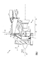
Figure 1 is a sectional view of an example gas turbine engine mounting system. -
Figure 2 is an exploded view of an example outer link assembly of the mounting system. -
Figure 3 is a front view of the example outer link assembly and upper thrust link of the mounting system. -
Figure 4 is a partial perspective view of the outer link assembly and upper thrust link of the mounting system. -
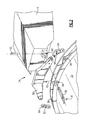
Figure 5 is a rear perspective view of lower thrust links for the example mounting system. -
Figure 6 is a rear view of the lower thrust links of the example mounting system. - Referring to
Figure 1 , a mounting system for a gasturbine engine assembly 10 is disclosed and includes anouter link assembly 34, anupper thrust link 36 and first andsecond thrust links gas turbine engine 10 along asingle plane 46 to asupport structure 14 mounted to anairframe section 16. The example gasturbine engine assembly 10 includes acore engine 18 centered along anaxis 48 that drives afan 20 for generating a desired amount of thrust T. Theexample support structure 14 is a portion of a pylon mounted to a wing of an aircraft; however, the other engine mounting locations and structures are within the contemplation of this disclosure. - The
example core engine 18 includes acompressor section 28 that feeds incoming air to acombustor section 30. Fuel is mixed with the incoming air and ignited in thecombustor section 30 to produce a flow of gases that drives theturbine section 32. Theturbine section 32 in turn drives thecompressor section 28 and thefan 20. Anouter nacelle 12 surrounds thefan 20 and directs airflow into thecore engine 18. - During operation the mounting system transfer thrust T to the
airframe section 16 and is vertically, laterally, and torsionally stiff to withstand engine torque and maneuver loads while providing for airflow through theengine assembly 10. Further, larger sizes offans 20 necessarily require largeropening nacelle section 12 that in turn increases air loading L during takeoff and other high angle of attack maneuvers. The disclosed mounting systems supports the gas turbine engine along thesingle plane 46 to separate the air loads L and other maneuver loads from thecore engine 18. The separation of the air loads L and maneuver loads reduces bending stress on thecore engine 18. - The gas
turbine engine assembly 10 includes afan case 22 centered on thecenterline 48 and is radially spaced from afront case 24 of thecore engine 18. A plurality of guide vanes 25. Anintermediate case 26 is disposed just aft of thefront case 24. Theouter link assembly 34 and theupper thrust link 36 secure thefan case 22 to thesupport 14. Theouter link assembly 34 supports vertical V and side S loads produced or exerted on thegas turbine engine 10. Theupper thrust link 36 accommodates torque loads t produced and/or exerted on theengine 10 from air loading L. - The
lower thrust links front case 24 and on a second end to thesupport 14. Acenter thrust link 40 further transfers thrust produced by theengine assembly 10 to theairframe 16. Thelower thrust links engine assembly 10 to thesupport structure 14 and into thecenter thrust link 40 and theairframe 16. - Each of the attachment points to the
engine assembly 10 for theouter link assembly 34, theupper thrust link 36 and thelower thrust links common plane 46 transverse to thecenterline 48. - A
core support structure 42 is attached to thefront case 24 and theintermediate case 26 to support the weight of thecore engine 18. Thecore support 42 is cantilevered rearward to hang over thecore support 42 at a position aft of theintermediate case 26. Asupport link 44 extends from thecore support structure 42 to accommodate and support the weight W of thecore engine 18. - Referring to
Figure 2 , theouter link assembly 34 is a four bar linkage including afixed link 50 that mounts to thesupport structure 14. Thefixed link 50 is disposed within theplane 46 and extends outward relative to the 48 centerline of theengine assembly 10. Thefixed link 50 includes arms that extend outward and received afirst link 52 and asecond link 54. Thefirst link 52 includes one opening 64 for pivotal attachment to thefixed link 50. The single attachment point between thefirst link 52 and thefixed link 52 constrains relative vertical movement, but allows relative side to side movement. - The second link includes two
openings 64 that are attached to corresponding openings in thefixed link 50. The two point attachment between thesecond link 54 and the fixed link constrain vertical and side to side movement of theengine assembly 10 relative to thesupport structure 14. - The
upper thrust link 36 extends through aslot 58 of thefan case 22 and is received within apocket 60 defined by thesupport structure 14. Amounting fastener 62 secures thethrust link 36 within theslot 58 and thepocket 60. Thethrust link 36 includes ahandle portion 35 that aids the attachment process of thegas turbine engine 10 to the support structure. - Referring to
Figures 3 and4 , the assembledouter link assembly 34 andthrust link 36 is shown attached to thefan case 22. The first andsecond links fan case 22 through opening 66 withinlugs 56 that include openings to receivefasteners 62. Thefasteners 62 may be of such a design as utilized in engine mounting systems to maintain the required loads and remain attached during engine operating conditions. - Both the first and second links support vertical loads V exerted by the weight of the
engine assembly 10 and resulting from maneuvering loads exerted during aircraft operation. Thesecond link 54 includes the two attachment points within theplane 46 to constrain and prevent side loads S. - The
upper thrust link 36 is secured in place by thefasteners 62 and constrains torque loads t exerted on theouter link assembly 34. The torque loads t are encountered as a combination of thrust T produced by theengine assembly 10 and air loading L exerted on thenacelle 12 during take off and other high angle of attack maneuvers. Theupper thrust link 36 is inserted through theslot 58 and received within thepocket 60 in thesupport structure 14 to provide the desired loading constraint, and also to aid in the mounting operation. The upper thrust link 36 is disposed parallel to theengine centerline 48. The thrust link 36 includes thehandle 35 that can be utilized to either push thethrust link 36 into thepocket 60, or to pull the thrust link 36 from thepocket 60 when it is desired to remove theengine assembly 10. - The
slot 58 of that receives thethrust link 36 is disposed within thesingle plane 46, along with the attachment points provided by thelugs 56 for the first andsecond links single plane 46. Theexample plane 46 is transverse to the center line of thecore engine 18 to provide for the separation of bending stresses induced on the airframe by aircraft maneuvering loads from thecore engine 18. - Referring to
Figures 5 and 6 , twolower thrust links engine centerline 48 to thefront case 24. Each of the lower thrust links extend from the firstattachment point end 68 on thefront face case 24 upwardly to a secondattachment point end 70 on thesupport structure 14. The firstattachment point end 68 is disposed below thecenterline 48 opposite from the side of thecenterline 48 in which theouter link assembly 34 and upper thrust link 36 are attached. - The two
lower thrust links attachment point end 68 on an outer circumference of thefront case 24, toward each other to the secondattachment point end 70 on thesupport structure 14. The center thrustlink 40 is attached to thesupport structure 14 between the second attachment point ends 70 of each of thelower thrust links link 40 transfers thrust forces T transmitted from thefront case 24 through thelower thrust links airframe 16. Thesupport structure 14 also receives and transfers the thrust forces T to theairframe 16. - The thrust loads T transferred by the
thrust links plane 46. Therefore, all of the loads exerted or placed on theengine assembly 10 are transferred through attachment points within a single plane that in turn reduces and substantially eliminates transference of bending loads into thecore engine 18. - A
core support structure 42 is provided to accommodate loads exerted by the cantilevered aft end of theengine core 18. Thecore support 42 is attached to thefront case 24 atattachment point 72 and to theintermediate case 26 at theattachment point 74. Theattachment point 72 is disposed within theplane 46. Thecore support 42 extends aft of theintermediate case 26 in a cantilevered manner. Asupport link 44 extends from the aft end of thecore support 42 and attached to thecore engine 18. Thesupport link 44 supports the core engine at a location aft of theintermediate case 26 to support the core engine weight to reduce and/or eliminate bending stresses caused by the weight of thecore engine 18. - Accordingly, the disclosed mounting system supports the gas
turbine engine assembly 10 along a single plane transverse to theengine centerline 48 to separate bending stresses encountered by the airframe during operation from thecore engine 18. - Although a preferred embodiment of this invention has been disclosed, a worker of ordinary skill in this art would recognize that certain modifications would come within the scope of this invention. For that reason, the following claims should be studied to determine the true scope and content of this invention.
Claims (15)
- A mounting system for securing a gas turbine engine (10) to an aircraft support structure (14) comprising:an outer link assembly (34) attachable to the aircraft support structure (14) and the gas turbine engine (10), the outer link assembly (34) including first and second links (52,54) disposed in a first plane (46) transverse to the centerline (48) of the gas turbine engine (10) and an upper thrust link (36) disposed along the centerline (48); andat least one lower thrust link (38A,38B) attachable to the aircraft support structure (14) and the gas turbine engine (10), the at least one lower thrust link (38A,38B) attached to the gas turbine engine (10) at a mount location within the first plane (46) transverse to the centerline (48) of the gas turbine engine (10).
- The mounting system as recited in claim 1, wherein the first and second links (52,54) of the outer link assembly (34) are attached on one end to an outer surface of an outer case of the gas turbine engine (10), optionally at circumferentially spaced apart locations (56) within the first plane (46), and at a second end to a fixed link (50) secured to the support structure (14).
- The mounting system as recited in claim 2, wherein one of the first and second links (52,54) is pivotally secured to the fixed link (50) for movement within the first plane (46) transverse to the centerline (48) of the gas turbine engine (10).
- The mounting system as recited in claim 2 or 3, wherein one of the first and second links (52,54) is secured to the fixed link (50) to constrain movement within the first plane (46) transverse to the centerline (48) of the gas turbine engine (10).
- The mounting system as recited in claim 2, 3 or 4, wherein the upper thrust link (36) is attached to the outer case (22) parallel to the centerline (48) of the gas turbine engine (10) and on a second end to the aircraft support structure (14), and wherein the outer case (22) optionally includes a mounting slot (58) within which the upper thrust link (36) is secured such that a portion of the upper thrust link (36) extends from the mounting slot and is secured to the aircraft support structure (14).
- The mounting system as recited in any preceding claim, wherein the at least one lower thrust link (38A,38B) comprises first and second lower thrust links securable to a front case (24) of the gas turbine engine (10) within the first plane (46).
- The mounting system as recited in claim 6, wherein each of the first and second lower thrust links (38A,38B) is securable to an outer perimeter of the front case at a location within the first plane (46) on a side opposite the gas turbine engine centerline (48) from the outer link assembly (34).
- The mounting system as recited in claim 6 or 7, wherein each of the first and second lower thrust links (38A,38B) is securable to the aircraft support structure (14) at a location centered over the gas turbine engine centerline (48).
- The mounting system as recited in claim 8, including a center thrust link (40) attachable to the aircraft support structure (14) at the location where the first and second lower thrust links (38A,38B) are secured and to a position on the support structure (14) aft of the location where the first and second lower thrust links (38A,38B) are secured.
- The mounting system as recited in any preceding claim, including a core support (42) securable to a front case (24) of the gas turbine engine (10) within the first plane (46) and including a support link (44) attached to a core portion of the gas turbine engine (10) spaced axially aft from the first plane (46), the core support (42) optionally being securable at a second location to an intermediate case (26) of the gas turbine engine (10) disposed between the front case (24) and the support link (44).
- The mounting system as recited in any preceding claim wherein the outer link assembly (34) is secured to the aircraft support structure (14) at a location forward of the location at which the at least one lower thrust link (38A,38B) is attached to the aircraft support structure (14).
- A gas turbine engine comprising:a core engine assembly including a fan case (22) and a front case (24) disposed along an engine centerline (48);a support structure (14) mountable to an aircraft;an outer link assembly (34) attached to the fan case (22) and to the support structure (14) along a first plane (46) transverse to the centerline (48);an upper thrust link (36) attached to the fan case (22) and to the support structure (14) along the centerline (48) within the first plane (46); andfirst and second lower thrust links (38A,38B) attached to the front case (22) within the first plane (46) at a first end and to the support structure (14) at a second end.
- The gas turbine engine as recited in claim 12, wherein the outer link assembly (34) includes first and second links (52,54) attached to the fan case (22) on one end and to a fixed link (50) on a second end, the fixed link (50) attached to the support structure (14) and the first and second links (52,54) spaced circumferentially apart from each other, and wherein, optionally, the first link (52) is pivotally attached to both the fan case and the fixed link (50) to constrain relative vertical movement between the core engine (18) and the support structure (14) and the second link (54) includes two attachment points (64) to the fixed link (50) to constrain vertical and side movement of the core engine (18) relative to the support structure (14).
- The gas turbine engine as recited in claim 12 or 13, wherein the upper thrust link (36) is secured partially within a slot (58) on the fan case (22) and extends outward from the slot (58) into the support structure (14) along the centerline (48).
- The gas turbine engine as recited in claim 12, 13 or 14, including a core support (42) securable to the front case (24) of the gas turbine engine within the first plane (46) and including a support link (44) attached to a core portion of the gas turbine engine spaced axially aft from the first plane (46), wherein the core support (42) is securable at a second location to an intermediate case (26) of the gas turbine engine disposed between the inner case and the support link (44).
Applications Claiming Priority (1)
| Application Number | Priority Date | Filing Date | Title |
|---|---|---|---|
| US12/629,317 US8672260B2 (en) | 2009-12-02 | 2009-12-02 | Single plane mount system for gas turbine engine |
Publications (4)
| Publication Number | Publication Date |
|---|---|
| EP2332835A2 true EP2332835A2 (en) | 2011-06-15 |
| EP2332835A3 EP2332835A3 (en) | 2013-06-19 |
| EP2332835B1 EP2332835B1 (en) | 2016-10-12 |
| EP2332835B8 EP2332835B8 (en) | 2016-12-07 |
Family
ID=43640105
Family Applications (1)
| Application Number | Title | Priority Date | Filing Date |
|---|---|---|---|
| EP10252040.0A Active EP2332835B8 (en) | 2009-12-02 | 2010-12-01 | Single plane mount system for gas turbine engine |
Country Status (2)
| Country | Link |
|---|---|
| US (1) | US8672260B2 (en) |
| EP (1) | EP2332835B8 (en) |
Cited By (4)
| Publication number | Priority date | Publication date | Assignee | Title |
|---|---|---|---|---|
| WO2014099085A2 (en) | 2012-10-01 | 2014-06-26 | United Technologies Corporation | Gas turbine engine with forward moment arm |
| FR3065442A1 (en) * | 2017-04-25 | 2018-10-26 | Airbus Operations | AIRCRAFT ENGINE ASSEMBLY COMPRISING A FRONT ENGINE ATTACHMENT INTEGRATED WITH THE BOX OF THE ATTACHING MAT |
| WO2018233860A1 (en) | 2017-06-21 | 2018-12-27 | Airbus Operations (S.A.S.) | ENGINE ASSEMBLY FOR AN AIRCRAFT |
| US11635025B2 (en) | 2012-10-01 | 2023-04-25 | Raytheon Technologies Corporation | Gas turbine engine with forward moment arm |
Families Citing this family (22)
| Publication number | Priority date | Publication date | Assignee | Title |
|---|---|---|---|---|
| FR2915175B1 (en) * | 2007-04-20 | 2009-07-17 | Airbus France Sa | ENGINE ATTACHING MACHINE FOR AN AIRCRAFT HAVING A REAR ENGINE ATTACHMENT BEAM DEPORTEE FROM THE HOUSING |
| US20130074517A1 (en) * | 2011-09-23 | 2013-03-28 | United Technologies Corporation | Gas turbine engine mount assembly |
| FR2981047B1 (en) * | 2011-10-06 | 2013-10-25 | Aircelle Sa | PROPELLANT AIRCRAFT ASSEMBLY |
| US9194296B2 (en) | 2012-05-18 | 2015-11-24 | Pratt & Whitney Canada Corp. | Inner bypass duct wall attachment |
| US9410441B2 (en) | 2012-09-13 | 2016-08-09 | Pratt & Whitney Canada Corp. | Turboprop engine with compressor turbine shroud |
| US20140084129A1 (en) * | 2012-09-27 | 2014-03-27 | United Technologies Corporation | Assembly for mounting a turbine engine case to a pylon |
| EP2904239B1 (en) | 2012-10-02 | 2020-05-06 | United Technologies Corporation | Assembly comprising a geared turbofan, a pylon and a wing |
| CN103101628B (en) * | 2013-02-06 | 2015-05-27 | 中国商用飞机有限责任公司 | Front mounting joint integrated with airplane hanging |
| GB201306674D0 (en) * | 2013-04-12 | 2013-05-29 | Rolls Royce Plc | Rigid Raft for a Gas Turbine Engine |
| US9238511B2 (en) * | 2014-03-04 | 2016-01-19 | Mra Systems, Inc. | Engine pylon structure |
| US20160167798A1 (en) * | 2014-12-12 | 2016-06-16 | General Electric Company | Variable pitch mounting for aircraft gas turbine engine |
| US10711631B2 (en) | 2014-12-24 | 2020-07-14 | Raytheon Technologies Corporation | Turbine engine with guide vanes forward of its fan blades |
| GB2547020A (en) * | 2016-02-04 | 2017-08-09 | Alexander Dennison Crawford Tristan | Design relating to improving aircraft |
| US10502091B2 (en) * | 2016-12-12 | 2019-12-10 | United Technologies Corporation | Sync ring assembly and associated clevis including a rib |
| US10197213B2 (en) * | 2017-01-26 | 2019-02-05 | General Electric Company | Systems and methods for mounting a rotatable machine |
| US10882629B2 (en) * | 2018-08-07 | 2021-01-05 | The Boeing Company | Roll load bearing aircraft propulsor moveable panel systems and methods |
| FR3086925B1 (en) * | 2018-10-08 | 2020-09-11 | Safran Aircraft Engines | TURBOMACHINE SUSPENSION KIT |
| FR3123377B1 (en) * | 2021-05-27 | 2023-05-19 | Safran Aircraft Engines | Support assembly for an aircraft turbine engine accessory box |
| FR3124825B1 (en) | 2021-06-30 | 2023-05-26 | Safran Aircraft Engines | PROPELLER FOR AN AIRCRAFT TURBOMACHINE WITH A VARIABLE-PITCHED BLADE AND A GEARED COUNTERWEIGHT DEVICE |
| FR3126695A1 (en) * | 2021-09-03 | 2023-03-10 | Airbus Operations | FRONT ENGINE MOUNT SYSTEM FOR AN AIRCRAFT ENGINE THAT FEATURES A COMPACT STRUCTURE |
| US12612170B2 (en) * | 2024-01-29 | 2026-04-28 | Airbus Operations Sas | Forward engine mount with converging links |
| US12545415B1 (en) | 2025-06-06 | 2026-02-10 | Rtx Corporation | Gas turbine engine aircraft mounting system |
Family Cites Families (21)
| Publication number | Priority date | Publication date | Assignee | Title |
|---|---|---|---|---|
| US3979087A (en) * | 1975-07-02 | 1976-09-07 | United Technologies Corporation | Engine mount |
| US4428189A (en) * | 1980-04-02 | 1984-01-31 | United Technologies Corporation | Case deflection control in aircraft gas turbine engines |
| US4531694A (en) * | 1982-10-18 | 1985-07-30 | Soloy Conversions, Ltd. | Turbine engine drive and mounting assembly for fixed wing aircraft |
| US4658579A (en) * | 1983-07-14 | 1987-04-21 | United Technologies Corporation | Load sharing for engine nacelle |
| GB2271390B (en) * | 1992-10-12 | 1995-07-05 | Rolls Royce Plc | Mounting for a gas turbine engine |
| GB2275308B (en) | 1993-02-20 | 1997-02-26 | Rolls Royce Plc | A mounting for coupling a turbofan gas turbine engine to an aircraft structure |
| US5452575A (en) * | 1993-09-07 | 1995-09-26 | General Electric Company | Aircraft gas turbine engine thrust mount |
| US5524847A (en) * | 1993-09-07 | 1996-06-11 | United Technologies Corporation | Nacelle and mounting arrangement for an aircraft engine |
| US5467941A (en) * | 1993-12-30 | 1995-11-21 | The Boeing Company | Pylon and engine installation for ultra-high by-pass turbo-fan engines |
| WO1996020111A1 (en) * | 1994-12-23 | 1996-07-04 | United Technologies Corporation | A mounting arrangement for a gas turbine engine |
| GB2303884B (en) * | 1995-04-13 | 1999-07-14 | Rolls Royce Plc | A mounting for coupling a turbofan gas turbine engine to an aircraft structure |
| US5620154A (en) * | 1995-05-03 | 1997-04-15 | The Boeing Company | Three link failsafe engine mount |
| US6517027B1 (en) * | 2001-12-03 | 2003-02-11 | Pratt & Whitney Canada Corp. | Flexible/fixed support for engine cowl |
| FR2855495B1 (en) | 2003-05-27 | 2006-11-24 | Snecma Moteurs | DEVICE FOR FRONT ATTACHMENT OF AIRCRAFT ENGINE |
| FR2867157B1 (en) * | 2004-03-04 | 2006-06-02 | Airbus France | MOUNTING SYSTEM INTERFERRED BETWEEN AN AIRCRAFT ENGINE AND A RIGID STRUCTURE OF A FIXED HINGING MACHINE UNDER A VESSEL OF THAT AIRCRAFT. |
| FR2867158B1 (en) * | 2004-03-04 | 2007-06-08 | Airbus France | MOUNTING SYSTEM INTERFERRED BETWEEN AN AIRCRAFT ENGINE AND A RIGID STRUCTURE OF A FIXED HINGING MACHINE UNDER A VESSEL OF THAT AIRCRAFT. |
| FR2869874B1 (en) * | 2004-05-04 | 2006-06-23 | Snecma Moteurs Sa | AIRCRAFT ENGINE WITH MEANS OF SUSPENSION TO THE STRUCTURE OF AN AIRCRAFT |
| US7104306B2 (en) * | 2004-06-14 | 2006-09-12 | The Boeing Company | Cast unitized primary truss structure and method |
| FR2873987B1 (en) * | 2004-08-05 | 2006-11-24 | Airbus France Sas | AIRCRAFT ENGINE ASSEMBLY |
| GB0622405D0 (en) * | 2006-11-10 | 2006-12-20 | Rolls Royce Plc | A turbine engine mounting arrangement |
| FR2921900B1 (en) | 2007-10-05 | 2011-03-18 | Aircelle Sa | PROPULSIVE ASSEMBLY FOR AIRCRAFT. |
-
2009
- 2009-12-02 US US12/629,317 patent/US8672260B2/en not_active Expired - Fee Related
-
2010
- 2010-12-01 EP EP10252040.0A patent/EP2332835B8/en active Active
Non-Patent Citations (1)
| Title |
|---|
| None |
Cited By (7)
| Publication number | Priority date | Publication date | Assignee | Title |
|---|---|---|---|---|
| WO2014099085A2 (en) | 2012-10-01 | 2014-06-26 | United Technologies Corporation | Gas turbine engine with forward moment arm |
| EP2904210A4 (en) * | 2012-10-01 | 2015-12-02 | United Technologies Corp | GAS TURBINE WITH FRONT LEVER ARM |
| US11635025B2 (en) | 2012-10-01 | 2023-04-25 | Raytheon Technologies Corporation | Gas turbine engine with forward moment arm |
| FR3065442A1 (en) * | 2017-04-25 | 2018-10-26 | Airbus Operations | AIRCRAFT ENGINE ASSEMBLY COMPRISING A FRONT ENGINE ATTACHMENT INTEGRATED WITH THE BOX OF THE ATTACHING MAT |
| WO2018233860A1 (en) | 2017-06-21 | 2018-12-27 | Airbus Operations (S.A.S.) | ENGINE ASSEMBLY FOR AN AIRCRAFT |
| FR3068008A1 (en) * | 2017-06-21 | 2018-12-28 | Airbus Operations | ENGINE ASSEMBLY FOR AN AIRCRAFT |
| US11542022B2 (en) | 2017-06-21 | 2023-01-03 | Airbus Operations Sas | Aircraft propulsion assembly |
Also Published As
| Publication number | Publication date |
|---|---|
| EP2332835B8 (en) | 2016-12-07 |
| EP2332835A3 (en) | 2013-06-19 |
| US8672260B2 (en) | 2014-03-18 |
| EP2332835B1 (en) | 2016-10-12 |
| US20110127368A1 (en) | 2011-06-02 |
Similar Documents
| Publication | Publication Date | Title |
|---|---|---|
| US8672260B2 (en) | Single plane mount system for gas turbine engine | |
| EP2202153B1 (en) | Monolithic structure for mounting aircraft engine | |
| US8876042B2 (en) | Integrated nacelle assembly | |
| US8356769B2 (en) | Aircraft engine assembly comprising a fan cowl-supporting cradle mounted on two separate elements | |
| EP2080700B1 (en) | Pylon and engine mount configuration | |
| US8162254B2 (en) | Aircraft engine assembly comprising a junction aerodynamic fairing mounted on two separate elements | |
| US9567090B2 (en) | Pylon for mounting an engine on the structure of an aircraft | |
| CN100519340C (en) | Strut for locking the engine of an aircraft | |
| EP2718185B1 (en) | System and method for mounting an aircraft engine | |
| EP3497017B1 (en) | Mounting systems for aircraft engines | |
| US8042342B2 (en) | Engine assembly for aircraft comprising an engine as well as a device for locking said engine | |
| EP2441673B1 (en) | Support structure | |
| US9481470B2 (en) | Intermediate structure for independently de-mountable propulsion components | |
| CN101784441A (en) | Support brackets for the fan cover mounted on the hanger and engine compartment air intake | |
| EP2537755A2 (en) | Mounting assembly | |
| EP1712466B1 (en) | Gas turbine engine mounting arrangement | |
| US20040227033A1 (en) | Turboprop carrier structure and an assembly including such a carrier structure | |
| EP3556661B1 (en) | Engine inlet system with integral firewall seal | |
| US20080272230A1 (en) | Engine Assembly for Aircraft | |
| EP1764306A2 (en) | Auxiliary power unit case flange to cone bolt adapter | |
| EP3877254A2 (en) | Engine mounted aircraft gearbox disposed in pylon |
Legal Events
| Date | Code | Title | Description |
|---|---|---|---|
| PUAI | Public reference made under article 153(3) epc to a published international application that has entered the european phase |
Free format text: ORIGINAL CODE: 0009012 |
|
| AK | Designated contracting states |
Kind code of ref document: A2 Designated state(s): AL AT BE BG CH CY CZ DE DK EE ES FI FR GB GR HR HU IE IS IT LI LT LU LV MC MK MT NL NO PL PT RO RS SE SI SK SM TR |
|
| AX | Request for extension of the european patent |
Extension state: BA ME |
|
| PUAL | Search report despatched |
Free format text: ORIGINAL CODE: 0009013 |
|
| AK | Designated contracting states |
Kind code of ref document: A3 Designated state(s): AL AT BE BG CH CY CZ DE DK EE ES FI FR GB GR HR HU IE IS IT LI LT LU LV MC MK MT NL NO PL PT RO RS SE SI SK SM TR |
|
| AX | Request for extension of the european patent |
Extension state: BA ME |
|
| RIC1 | Information provided on ipc code assigned before grant |
Ipc: B64D 27/20 20060101AFI20130515BHEP Ipc: B64D 27/26 20060101ALI20130515BHEP |
|
| 17P | Request for examination filed |
Effective date: 20131219 |
|
| RBV | Designated contracting states (corrected) |
Designated state(s): AL AT BE BG CH CY CZ DE DK EE ES FI FR GB GR HR HU IE IS IT LI LT LU LV MC MK MT NL NO PL PT RO RS SE SI SK SM TR |
|
| 17Q | First examination report despatched |
Effective date: 20150612 |
|
| GRAP | Despatch of communication of intention to grant a patent |
Free format text: ORIGINAL CODE: EPIDOSNIGR1 |
|
| INTG | Intention to grant announced |
Effective date: 20160420 |
|
| GRAS | Grant fee paid |
Free format text: ORIGINAL CODE: EPIDOSNIGR3 |
|
| GRAA | (expected) grant |
Free format text: ORIGINAL CODE: 0009210 |
|
| AK | Designated contracting states |
Kind code of ref document: B1 Designated state(s): AL AT BE BG CH CY CZ DE DK EE ES FI FR GB GR HR HU IE IS IT LI LT LU LV MC MK MT NL NO PL PT RO RS SE SI SK SM TR |
|
| REG | Reference to a national code |
Ref country code: GB Ref legal event code: FG4D |
|
| REG | Reference to a national code |
Ref country code: CH Ref legal event code: EP |
|
| REG | Reference to a national code |
Ref country code: AT Ref legal event code: REF Ref document number: 836243 Country of ref document: AT Kind code of ref document: T Effective date: 20161015 |
|
| RAP2 | Party data changed (patent owner data changed or rights of a patent transferred) |
Owner name: UNITED TECHNOLOGIES CORPORATION |
|
| REG | Reference to a national code |
Ref country code: IE Ref legal event code: FG4D |
|
| REG | Reference to a national code |
Ref country code: DE Ref legal event code: R096 Ref document number: 602010037106 Country of ref document: DE |
|
| REG | Reference to a national code |
Ref country code: DE Ref legal event code: R082 Ref document number: 602010037106 Country of ref document: DE Representative=s name: SCHMITT-NILSON SCHRAUD WAIBEL WOHLFROM PATENTA, DE Ref country code: DE Ref legal event code: R082 Ref document number: 602010037106 Country of ref document: DE Representative=s name: KSNH PATENTANWAELTE KLUNKER/SCHMITT-NILSON/HIR, DE |
|
| REG | Reference to a national code |
Ref country code: LT Ref legal event code: MG4D |
|
| REG | Reference to a national code |
Ref country code: NL Ref legal event code: MP Effective date: 20161012 |
|
| PG25 | Lapsed in a contracting state [announced via postgrant information from national office to epo] |
Ref country code: LV Free format text: LAPSE BECAUSE OF FAILURE TO SUBMIT A TRANSLATION OF THE DESCRIPTION OR TO PAY THE FEE WITHIN THE PRESCRIBED TIME-LIMIT Effective date: 20161012 |
|
| REG | Reference to a national code |
Ref country code: AT Ref legal event code: MK05 Ref document number: 836243 Country of ref document: AT Kind code of ref document: T Effective date: 20161012 |
|
| PG25 | Lapsed in a contracting state [announced via postgrant information from national office to epo] |
Ref country code: LT Free format text: LAPSE BECAUSE OF FAILURE TO SUBMIT A TRANSLATION OF THE DESCRIPTION OR TO PAY THE FEE WITHIN THE PRESCRIBED TIME-LIMIT Effective date: 20161012 Ref country code: GR Free format text: LAPSE BECAUSE OF FAILURE TO SUBMIT A TRANSLATION OF THE DESCRIPTION OR TO PAY THE FEE WITHIN THE PRESCRIBED TIME-LIMIT Effective date: 20170113 Ref country code: SE Free format text: LAPSE BECAUSE OF FAILURE TO SUBMIT A TRANSLATION OF THE DESCRIPTION OR TO PAY THE FEE WITHIN THE PRESCRIBED TIME-LIMIT Effective date: 20161012 Ref country code: NO Free format text: LAPSE BECAUSE OF FAILURE TO SUBMIT A TRANSLATION OF THE DESCRIPTION OR TO PAY THE FEE WITHIN THE PRESCRIBED TIME-LIMIT Effective date: 20170112 |
|
| PG25 | Lapsed in a contracting state [announced via postgrant information from national office to epo] |
Ref country code: RS Free format text: LAPSE BECAUSE OF FAILURE TO SUBMIT A TRANSLATION OF THE DESCRIPTION OR TO PAY THE FEE WITHIN THE PRESCRIBED TIME-LIMIT Effective date: 20161012 Ref country code: ES Free format text: LAPSE BECAUSE OF FAILURE TO SUBMIT A TRANSLATION OF THE DESCRIPTION OR TO PAY THE FEE WITHIN THE PRESCRIBED TIME-LIMIT Effective date: 20161012 Ref country code: HR Free format text: LAPSE BECAUSE OF FAILURE TO SUBMIT A TRANSLATION OF THE DESCRIPTION OR TO PAY THE FEE WITHIN THE PRESCRIBED TIME-LIMIT Effective date: 20161012 Ref country code: PL Free format text: LAPSE BECAUSE OF FAILURE TO SUBMIT A TRANSLATION OF THE DESCRIPTION OR TO PAY THE FEE WITHIN THE PRESCRIBED TIME-LIMIT Effective date: 20161012 Ref country code: PT Free format text: LAPSE BECAUSE OF FAILURE TO SUBMIT A TRANSLATION OF THE DESCRIPTION OR TO PAY THE FEE WITHIN THE PRESCRIBED TIME-LIMIT Effective date: 20170213 Ref country code: IS Free format text: LAPSE BECAUSE OF FAILURE TO SUBMIT A TRANSLATION OF THE DESCRIPTION OR TO PAY THE FEE WITHIN THE PRESCRIBED TIME-LIMIT Effective date: 20170212 Ref country code: FI Free format text: LAPSE BECAUSE OF FAILURE TO SUBMIT A TRANSLATION OF THE DESCRIPTION OR TO PAY THE FEE WITHIN THE PRESCRIBED TIME-LIMIT Effective date: 20161012 Ref country code: AT Free format text: LAPSE BECAUSE OF FAILURE TO SUBMIT A TRANSLATION OF THE DESCRIPTION OR TO PAY THE FEE WITHIN THE PRESCRIBED TIME-LIMIT Effective date: 20161012 Ref country code: BE Free format text: LAPSE BECAUSE OF FAILURE TO SUBMIT A TRANSLATION OF THE DESCRIPTION OR TO PAY THE FEE WITHIN THE PRESCRIBED TIME-LIMIT Effective date: 20161012 Ref country code: NL Free format text: LAPSE BECAUSE OF FAILURE TO SUBMIT A TRANSLATION OF THE DESCRIPTION OR TO PAY THE FEE WITHIN THE PRESCRIBED TIME-LIMIT Effective date: 20161012 |
|
| REG | Reference to a national code |
Ref country code: DE Ref legal event code: R082 Ref document number: 602010037106 Country of ref document: DE Representative=s name: SCHMITT-NILSON SCHRAUD WAIBEL WOHLFROM PATENTA, DE |
|
| REG | Reference to a national code |
Ref country code: DE Ref legal event code: R097 Ref document number: 602010037106 Country of ref document: DE |
|
| PG25 | Lapsed in a contracting state [announced via postgrant information from national office to epo] |
Ref country code: SK Free format text: LAPSE BECAUSE OF FAILURE TO SUBMIT A TRANSLATION OF THE DESCRIPTION OR TO PAY THE FEE WITHIN THE PRESCRIBED TIME-LIMIT Effective date: 20161012 Ref country code: RO Free format text: LAPSE BECAUSE OF FAILURE TO SUBMIT A TRANSLATION OF THE DESCRIPTION OR TO PAY THE FEE WITHIN THE PRESCRIBED TIME-LIMIT Effective date: 20161012 Ref country code: CZ Free format text: LAPSE BECAUSE OF FAILURE TO SUBMIT A TRANSLATION OF THE DESCRIPTION OR TO PAY THE FEE WITHIN THE PRESCRIBED TIME-LIMIT Effective date: 20161012 Ref country code: EE Free format text: LAPSE BECAUSE OF FAILURE TO SUBMIT A TRANSLATION OF THE DESCRIPTION OR TO PAY THE FEE WITHIN THE PRESCRIBED TIME-LIMIT Effective date: 20161012 Ref country code: DK Free format text: LAPSE BECAUSE OF FAILURE TO SUBMIT A TRANSLATION OF THE DESCRIPTION OR TO PAY THE FEE WITHIN THE PRESCRIBED TIME-LIMIT Effective date: 20161012 |
|
| REG | Reference to a national code |
Ref country code: CH Ref legal event code: PL |
|
| PLBE | No opposition filed within time limit |
Free format text: ORIGINAL CODE: 0009261 |
|
| STAA | Information on the status of an ep patent application or granted ep patent |
Free format text: STATUS: NO OPPOSITION FILED WITHIN TIME LIMIT |
|
| PG25 | Lapsed in a contracting state [announced via postgrant information from national office to epo] |
Ref country code: IT Free format text: LAPSE BECAUSE OF FAILURE TO SUBMIT A TRANSLATION OF THE DESCRIPTION OR TO PAY THE FEE WITHIN THE PRESCRIBED TIME-LIMIT Effective date: 20161012 Ref country code: BG Free format text: LAPSE BECAUSE OF FAILURE TO SUBMIT A TRANSLATION OF THE DESCRIPTION OR TO PAY THE FEE WITHIN THE PRESCRIBED TIME-LIMIT Effective date: 20170112 Ref country code: SM Free format text: LAPSE BECAUSE OF FAILURE TO SUBMIT A TRANSLATION OF THE DESCRIPTION OR TO PAY THE FEE WITHIN THE PRESCRIBED TIME-LIMIT Effective date: 20161012 |
|
| 26N | No opposition filed |
Effective date: 20170713 |
|
| PG25 | Lapsed in a contracting state [announced via postgrant information from national office to epo] |
Ref country code: MC Free format text: LAPSE BECAUSE OF FAILURE TO SUBMIT A TRANSLATION OF THE DESCRIPTION OR TO PAY THE FEE WITHIN THE PRESCRIBED TIME-LIMIT Effective date: 20161012 |
|
| REG | Reference to a national code |
Ref country code: FR Ref legal event code: ST Effective date: 20170831 |
|
| REG | Reference to a national code |
Ref country code: IE Ref legal event code: MM4A |
|
| PG25 | Lapsed in a contracting state [announced via postgrant information from national office to epo] |
Ref country code: FR Free format text: LAPSE BECAUSE OF NON-PAYMENT OF DUE FEES Effective date: 20170102 Ref country code: LI Free format text: LAPSE BECAUSE OF NON-PAYMENT OF DUE FEES Effective date: 20161231 Ref country code: CH Free format text: LAPSE BECAUSE OF NON-PAYMENT OF DUE FEES Effective date: 20161231 Ref country code: LU Free format text: LAPSE BECAUSE OF NON-PAYMENT OF DUE FEES Effective date: 20161201 |
|
| PG25 | Lapsed in a contracting state [announced via postgrant information from national office to epo] |
Ref country code: SI Free format text: LAPSE BECAUSE OF FAILURE TO SUBMIT A TRANSLATION OF THE DESCRIPTION OR TO PAY THE FEE WITHIN THE PRESCRIBED TIME-LIMIT Effective date: 20161012 Ref country code: IE Free format text: LAPSE BECAUSE OF NON-PAYMENT OF DUE FEES Effective date: 20161201 |
|
| PG25 | Lapsed in a contracting state [announced via postgrant information from national office to epo] |
Ref country code: HU Free format text: LAPSE BECAUSE OF FAILURE TO SUBMIT A TRANSLATION OF THE DESCRIPTION OR TO PAY THE FEE WITHIN THE PRESCRIBED TIME-LIMIT; INVALID AB INITIO Effective date: 20101201 Ref country code: CY Free format text: LAPSE BECAUSE OF FAILURE TO SUBMIT A TRANSLATION OF THE DESCRIPTION OR TO PAY THE FEE WITHIN THE PRESCRIBED TIME-LIMIT Effective date: 20161012 |
|
| PG25 | Lapsed in a contracting state [announced via postgrant information from national office to epo] |
Ref country code: MK Free format text: LAPSE BECAUSE OF FAILURE TO SUBMIT A TRANSLATION OF THE DESCRIPTION OR TO PAY THE FEE WITHIN THE PRESCRIBED TIME-LIMIT Effective date: 20161012 Ref country code: TR Free format text: LAPSE BECAUSE OF FAILURE TO SUBMIT A TRANSLATION OF THE DESCRIPTION OR TO PAY THE FEE WITHIN THE PRESCRIBED TIME-LIMIT Effective date: 20161012 |
|
| PG25 | Lapsed in a contracting state [announced via postgrant information from national office to epo] |
Ref country code: MT Free format text: LAPSE BECAUSE OF NON-PAYMENT OF DUE FEES Effective date: 20161201 |
|
| PG25 | Lapsed in a contracting state [announced via postgrant information from national office to epo] |
Ref country code: AL Free format text: LAPSE BECAUSE OF FAILURE TO SUBMIT A TRANSLATION OF THE DESCRIPTION OR TO PAY THE FEE WITHIN THE PRESCRIBED TIME-LIMIT Effective date: 20161012 |
|
| REG | Reference to a national code |
Ref country code: DE Ref legal event code: R081 Ref document number: 602010037106 Country of ref document: DE Owner name: RAYTHEON TECHNOLOGIES CORPORATION (N.D.GES.D.S, US Free format text: FORMER OWNER: UNITED TECHNOLOGIES CORPORATION, FARMINGTON, CONN., US Ref country code: DE Ref legal event code: R081 Ref document number: 602010037106 Country of ref document: DE Owner name: RTX CORPORATION (N.D.GES.D. STAATES DELAWARE),, US Free format text: FORMER OWNER: UNITED TECHNOLOGIES CORPORATION, FARMINGTON, CONN., US |
|
| P01 | Opt-out of the competence of the unified patent court (upc) registered |
Effective date: 20230519 |
|
| REG | Reference to a national code |
Ref country code: DE Ref legal event code: R081 Ref document number: 602010037106 Country of ref document: DE Owner name: RTX CORPORATION (N.D.GES.D. STAATES DELAWARE),, US Free format text: FORMER OWNER: RAYTHEON TECHNOLOGIES CORPORATION (N.D.GES.D.STAATES DELAWARE), ARLINGTON, VA, US |
|
| PGFP | Annual fee paid to national office [announced via postgrant information from national office to epo] |
Ref country code: DE Payment date: 20251126 Year of fee payment: 16 |
|
| PGFP | Annual fee paid to national office [announced via postgrant information from national office to epo] |
Ref country code: GB Payment date: 20251119 Year of fee payment: 16 |