EP2332643A1 - Compact device for mixing fluids in a reactor with downward flow - Google Patents
Compact device for mixing fluids in a reactor with downward flow Download PDFInfo
- Publication number
- EP2332643A1 EP2332643A1 EP10290593A EP10290593A EP2332643A1 EP 2332643 A1 EP2332643 A1 EP 2332643A1 EP 10290593 A EP10290593 A EP 10290593A EP 10290593 A EP10290593 A EP 10290593A EP 2332643 A1 EP2332643 A1 EP 2332643A1
- Authority
- EP
- European Patent Office
- Prior art keywords
- reactor
- chamber
- fluids
- mixing
- plate
- Prior art date
- Legal status (The legal status is an assumption and is not a legal conclusion. Google has not performed a legal analysis and makes no representation as to the accuracy of the status listed.)
- Granted
Links
- 238000002156 mixing Methods 0.000 title claims abstract description 136
- 239000012530 fluid Substances 0.000 title claims abstract description 119
- 238000002347 injection Methods 0.000 claims abstract description 22
- 239000007924 injection Substances 0.000 claims abstract description 22
- 238000006243 chemical reaction Methods 0.000 claims description 44
- 239000003054 catalyst Substances 0.000 claims description 25
- 238000010791 quenching Methods 0.000 description 36
- 239000000203 mixture Substances 0.000 description 34
- 230000000171 quenching effect Effects 0.000 description 31
- 239000007788 liquid Substances 0.000 description 20
- 239000007789 gas Substances 0.000 description 17
- 239000007791 liquid phase Substances 0.000 description 8
- 230000003197 catalytic effect Effects 0.000 description 7
- 238000004088 simulation Methods 0.000 description 7
- 238000011144 upstream manufacturing Methods 0.000 description 6
- 238000005984 hydrogenation reaction Methods 0.000 description 4
- 239000012071 phase Substances 0.000 description 4
- 238000005259 measurement Methods 0.000 description 3
- XLYOFNOQVPJJNP-UHFFFAOYSA-N water Substances O XLYOFNOQVPJJNP-UHFFFAOYSA-N 0.000 description 3
- 241000239290 Araneae Species 0.000 description 2
- 238000004517 catalytic hydrocracking Methods 0.000 description 2
- 238000000265 homogenisation Methods 0.000 description 2
- 238000000034 method Methods 0.000 description 2
- 238000000926 separation method Methods 0.000 description 2
- 239000007787 solid Substances 0.000 description 2
- IJGRMHOSHXDMSA-UHFFFAOYSA-N Atomic nitrogen Chemical compound N#N IJGRMHOSHXDMSA-UHFFFAOYSA-N 0.000 description 1
- UFHFLCQGNIYNRP-UHFFFAOYSA-N Hydrogen Chemical compound [H][H] UFHFLCQGNIYNRP-UHFFFAOYSA-N 0.000 description 1
- 238000009825 accumulation Methods 0.000 description 1
- 239000011324 bead Substances 0.000 description 1
- 238000004364 calculation method Methods 0.000 description 1
- 238000001816 cooling Methods 0.000 description 1
- 230000001955 cumulated effect Effects 0.000 description 1
- 229910001873 dinitrogen Inorganic materials 0.000 description 1
- 230000000694 effects Effects 0.000 description 1
- 235000021183 entrée Nutrition 0.000 description 1
- 239000008240 homogeneous mixture Substances 0.000 description 1
- 239000001257 hydrogen Substances 0.000 description 1
- 229910052739 hydrogen Inorganic materials 0.000 description 1
- 238000007670 refining Methods 0.000 description 1
- 238000004513 sizing Methods 0.000 description 1
- 239000011800 void material Substances 0.000 description 1
Images


Classifications
-
- B—PERFORMING OPERATIONS; TRANSPORTING
- B01—PHYSICAL OR CHEMICAL PROCESSES OR APPARATUS IN GENERAL
- B01J—CHEMICAL OR PHYSICAL PROCESSES, e.g. CATALYSIS OR COLLOID CHEMISTRY; THEIR RELEVANT APPARATUS
- B01J8/00—Chemical or physical processes in general, conducted in the presence of fluids and solid particles; Apparatus for such processes
- B01J8/02—Chemical or physical processes in general, conducted in the presence of fluids and solid particles; Apparatus for such processes with stationary particles, e.g. in fixed beds
- B01J8/04—Chemical or physical processes in general, conducted in the presence of fluids and solid particles; Apparatus for such processes with stationary particles, e.g. in fixed beds the fluid passing successively through two or more beds
- B01J8/0492—Feeding reactive fluids
-
- B—PERFORMING OPERATIONS; TRANSPORTING
- B01—PHYSICAL OR CHEMICAL PROCESSES OR APPARATUS IN GENERAL
- B01J—CHEMICAL OR PHYSICAL PROCESSES, e.g. CATALYSIS OR COLLOID CHEMISTRY; THEIR RELEVANT APPARATUS
- B01J8/00—Chemical or physical processes in general, conducted in the presence of fluids and solid particles; Apparatus for such processes
- B01J8/02—Chemical or physical processes in general, conducted in the presence of fluids and solid particles; Apparatus for such processes with stationary particles, e.g. in fixed beds
-
- B—PERFORMING OPERATIONS; TRANSPORTING
- B01—PHYSICAL OR CHEMICAL PROCESSES OR APPARATUS IN GENERAL
- B01F—MIXING, e.g. DISSOLVING, EMULSIFYING OR DISPERSING
- B01F25/00—Flow mixers; Mixers for falling materials, e.g. solid particles
- B01F25/40—Static mixers
-
- B—PERFORMING OPERATIONS; TRANSPORTING
- B01—PHYSICAL OR CHEMICAL PROCESSES OR APPARATUS IN GENERAL
- B01J—CHEMICAL OR PHYSICAL PROCESSES, e.g. CATALYSIS OR COLLOID CHEMISTRY; THEIR RELEVANT APPARATUS
- B01J19/00—Chemical, physical or physico-chemical processes in general; Their relevant apparatus
-
- B—PERFORMING OPERATIONS; TRANSPORTING
- B01—PHYSICAL OR CHEMICAL PROCESSES OR APPARATUS IN GENERAL
- B01J—CHEMICAL OR PHYSICAL PROCESSES, e.g. CATALYSIS OR COLLOID CHEMISTRY; THEIR RELEVANT APPARATUS
- B01J8/00—Chemical or physical processes in general, conducted in the presence of fluids and solid particles; Apparatus for such processes
- B01J8/02—Chemical or physical processes in general, conducted in the presence of fluids and solid particles; Apparatus for such processes with stationary particles, e.g. in fixed beds
- B01J8/04—Chemical or physical processes in general, conducted in the presence of fluids and solid particles; Apparatus for such processes with stationary particles, e.g. in fixed beds the fluid passing successively through two or more beds
- B01J8/0446—Chemical or physical processes in general, conducted in the presence of fluids and solid particles; Apparatus for such processes with stationary particles, e.g. in fixed beds the fluid passing successively through two or more beds the flow within the beds being predominantly vertical
- B01J8/0449—Chemical or physical processes in general, conducted in the presence of fluids and solid particles; Apparatus for such processes with stationary particles, e.g. in fixed beds the fluid passing successively through two or more beds the flow within the beds being predominantly vertical in two or more cylindrical beds
- B01J8/0453—Chemical or physical processes in general, conducted in the presence of fluids and solid particles; Apparatus for such processes with stationary particles, e.g. in fixed beds the fluid passing successively through two or more beds the flow within the beds being predominantly vertical in two or more cylindrical beds the beds being superimposed one above the other
-
- C—CHEMISTRY; METALLURGY
- C10—PETROLEUM, GAS OR COKE INDUSTRIES; TECHNICAL GASES CONTAINING CARBON MONOXIDE; FUELS; LUBRICANTS; PEAT
- C10G—CRACKING HYDROCARBON OILS; PRODUCTION OF LIQUID HYDROCARBON MIXTURES, e.g. BY DESTRUCTIVE HYDROGENATION, OLIGOMERISATION, POLYMERISATION; RECOVERY OF HYDROCARBON OILS FROM OIL-SHALE, OIL-SAND, OR GASES; REFINING MIXTURES MAINLY CONSISTING OF HYDROCARBONS; REFORMING OF NAPHTHA; MINERAL WAXES
- C10G45/00—Refining of hydrocarbon oils using hydrogen or hydrogen-generating compounds
- C10G45/02—Refining of hydrocarbon oils using hydrogen or hydrogen-generating compounds to eliminate hetero atoms without changing the skeleton of the hydrocarbon involved and without cracking into lower boiling hydrocarbons; Hydrofinishing
-
- C—CHEMISTRY; METALLURGY
- C10—PETROLEUM, GAS OR COKE INDUSTRIES; TECHNICAL GASES CONTAINING CARBON MONOXIDE; FUELS; LUBRICANTS; PEAT
- C10G—CRACKING HYDROCARBON OILS; PRODUCTION OF LIQUID HYDROCARBON MIXTURES, e.g. BY DESTRUCTIVE HYDROGENATION, OLIGOMERISATION, POLYMERISATION; RECOVERY OF HYDROCARBON OILS FROM OIL-SHALE, OIL-SAND, OR GASES; REFINING MIXTURES MAINLY CONSISTING OF HYDROCARBONS; REFORMING OF NAPHTHA; MINERAL WAXES
- C10G45/00—Refining of hydrocarbon oils using hydrogen or hydrogen-generating compounds
- C10G45/44—Hydrogenation of the aromatic hydrocarbons
-
- C—CHEMISTRY; METALLURGY
- C10—PETROLEUM, GAS OR COKE INDUSTRIES; TECHNICAL GASES CONTAINING CARBON MONOXIDE; FUELS; LUBRICANTS; PEAT
- C10G—CRACKING HYDROCARBON OILS; PRODUCTION OF LIQUID HYDROCARBON MIXTURES, e.g. BY DESTRUCTIVE HYDROGENATION, OLIGOMERISATION, POLYMERISATION; RECOVERY OF HYDROCARBON OILS FROM OIL-SHALE, OIL-SAND, OR GASES; REFINING MIXTURES MAINLY CONSISTING OF HYDROCARBONS; REFORMING OF NAPHTHA; MINERAL WAXES
- C10G47/00—Cracking of hydrocarbon oils, in the presence of hydrogen or hydrogen- generating compounds, to obtain lower boiling fractions
-
- B—PERFORMING OPERATIONS; TRANSPORTING
- B01—PHYSICAL OR CHEMICAL PROCESSES OR APPARATUS IN GENERAL
- B01J—CHEMICAL OR PHYSICAL PROCESSES, e.g. CATALYSIS OR COLLOID CHEMISTRY; THEIR RELEVANT APPARATUS
- B01J2208/00—Processes carried out in the presence of solid particles; Reactors therefor
- B01J2208/00008—Controlling the process
- B01J2208/00017—Controlling the temperature
- B01J2208/00327—Controlling the temperature by direct heat exchange
- B01J2208/00336—Controlling the temperature by direct heat exchange adding a temperature modifying medium to the reactants
- B01J2208/00353—Non-cryogenic fluids
- B01J2208/00362—Liquid
-
- B—PERFORMING OPERATIONS; TRANSPORTING
- B01—PHYSICAL OR CHEMICAL PROCESSES OR APPARATUS IN GENERAL
- B01J—CHEMICAL OR PHYSICAL PROCESSES, e.g. CATALYSIS OR COLLOID CHEMISTRY; THEIR RELEVANT APPARATUS
- B01J2208/00—Processes carried out in the presence of solid particles; Reactors therefor
- B01J2208/00008—Controlling the process
- B01J2208/00017—Controlling the temperature
- B01J2208/00327—Controlling the temperature by direct heat exchange
- B01J2208/00336—Controlling the temperature by direct heat exchange adding a temperature modifying medium to the reactants
- B01J2208/00353—Non-cryogenic fluids
- B01J2208/00371—Non-cryogenic fluids gaseous
Definitions
- the present invention relates to a compact device for mixing fluids in a downflow reactor and its use for carrying out exothermic reactions.
- the invention also relates to a reactor comprising a compact mixing device.
- the invention applies in the field of exothermic reactions and more particularly to hydrotreatment, hydrodesulphurization, hydrogenation, hydrocracking, hydrogenation and hydrodearomatization reactions.
- the exothermic reactions carried out in refining and / or in petrochemistry need to be cooled by an additional fluid to prevent thermal runaway of the reactor in which they are carried out. It is also necessary to keep a homogeneous temperature gradient within the reactor in order to avoid the existence of hot spots in the catalyst bed. These hot spots can prematurely decrease the activity of the catalyst. They also lead to non-selective reactions. It is therefore important to have at least one mixing chamber in a reactor which allows a uniform temperature distribution of the fluids and a cooling of the reaction fluids to a desired temperature.
- He is also known by the patent application FR-A-2824495 a quenching device for ensuring an effective exchange between the quench fluid (s) and the fluid (s) of the process.
- This device is integrated in an enclosure and comprises a quenching fluid injection pipe, a fluid collection baffle, the quench box itself, operating the mixing between the quenching fluid and the downflow, and a system dispensing system consisting of a perforated bowl and a distributor tray.
- the quench box comprises a deflector ensuring the swirling motion of the fluids in a substantially non-radial direction and not parallel to the axis of said chamber and downstream of the deflector, in the direction of circulation of the reaction fluid, at least one outlet passage section; of the fluid mixture formed in the box.
- the present invention therefore aims to overcome one or more of the disadvantages of the prior art by providing a compact mixing device.
- the device according to the invention allows a substantial gain in terms of the size of the reactor and ensures a good mixture of fluids and a good temperature homogeneity.
- a first object of the invention is to provide a compact device for mixing fluids in a downflow reactor.
- Another object of the invention relates to the use of a compact device for mixing fluids in a downflow reactor for carrying out exothermic reactions.
- Another object of the invention relates to a reactor comprising a compact device for mixing fluids.
- Another object of the invention relates to the use of a reactor comprising a compact device for mixing fluids for carrying out exothermic reactions.
- the injection means is located at the inlet end of the annular mixing chamber.
- the distance d2 between the predistribution plate and the annular mixing chamber is between 0 and 100 mm. Preferably, this distance is between 0.25 and 100 mm. Even more preferably, this distance is between 0.5 and 5 mm.
- the distance d2 between the predistribution plate and the annular mixing chamber is equal to 0 mm, the annular mixing chamber being in contact with the predistribution plate.
- the annular mixing chamber is positioned at the periphery of the reactor enclosure.
- the annular mixing chamber is positioned at a distance d 1 from the chamber of the reactor, the distance d 1 ranging from 0.5% to 25% of the reactor diameter.
- the diameter d of the annular mixing chamber is between 0.05 and 0.5 m.
- the diameter is between 0.1 and 0.3 m. Even more preferably, it is between 0.15 and 0.25 m.
- the length of the annular mixing chamber is between 90 and 270 degrees. Preferably, it is between 100 and 250 degrees. Even more preferably, it is between 130 and 200 degrees.
- the invention relates to the use of the compact mixing device for carrying out exothermic reactions.
- the invention relates to an elongated reactor along a substantially vertical axis in which at least one reaction fluid is circulated from the top to the bottom of said reactor through at least one catalyst bed, said reactor comprising downstream of the catalyst bed in the direction of circulation of said reaction fluid at least one compact mixing device.
- the reactor further comprises a substantially horizontal distribution plate positioned downstream of the compact mixing device in the direction of circulation of the fluids.
- the reactor further comprises a second catalyst bed located downstream of the compact mixing device and the distribution plate.
- the invention relates to the use for carrying out exothermic reactions of an elongated reactor along a substantially vertical axis in which the reactor is circulated from the top to the bottom of the reactor. minus one reaction fluid through at least one catalyst bed, said reactor comprising downstream of the catalyst bed in the direction of circulation of said reaction fluid at least one compact mixing device.
- the compact mixing device according to the invention is used in a reactor in which exothermic reactions such as hydrotreatment, hydrodesulfurization, hydrogenation, hydrocracking, hydrogenation and hydrodearomatization reactions take place.
- the reactor has an elongate shape along a substantially vertical axis. From the top to the bottom of said reactor is circulated at least one reaction fluid (or process fluid, according to the English terminology) through at least one catalyst bed. On leaving the bed, the reaction fluid is collected and then mixed with a quenching fluid (or quenching fluid, according to the English terminology) in the compact device according to the invention before being distributed to the downstream catalyst bed. of the distribution tray.
- the downstream and the upstream are defined with respect to the flow direction of the reaction fluid.
- the reaction fluid may be a gas or a liquid or a mixture containing liquid or gas; this depends on the type of reaction carried out in the reactor.
- the reaction fluid passing through the upstream catalyst bed is collected by a substantially horizontal collecting means (5) provided with a substantially vertical collection line (7) (cf. figure 1 ).
- substantially vertical and substantially horizontal (e) is meant in the sense of the present invention a variation of a plane with the vertical, respectively the horizon, of an angle ⁇ between ⁇ 5 degrees.
- the collection means consists of a solid plate disposed in the plane perpendicular to the longitudinal axis of the chamber under the grid of the catalytic bed. This plate extends radially over the entire surface of the reactor.
- the collection means serves to collect the flow of the reaction fluid from the upstream catalytic bed and directs this fluid to said collection line.
- the collection means is remote from the grid of the catalytic bed with a height (H1) creating a collection space (4). This space is necessary to allow the drainage of the reaction fluid to said pipe.
- This height H1 must be chosen so as to limit the pressure drop during the collection of fluid flowing from the catalyst bed (2) and to limit the guard height. The guard height must not affect the drainage of the reaction fluid to the collection line or its flow in this line.
- the height H1 is between 30 and 200 mm, preferably between 30 and 150 mm, even more preferably between 40 and 100 mm. According to one embodiment of the invention, the height H1 is equal to 100 mm.
- the vertical collection line (7) opens into the annular mixing chamber (9) at the inlet end of said chamber. This conduit directs the flow of reaction fluid and quench fluid into said chamber.
- the diameter of the vertical pipe (7) is chosen so as to limit the pressure drops. It will therefore be chosen so as to limit the flow rate, in said collection line, of (or) reaction fluid (s) from the catalyst bed located upstream of the collection means. Preferably, the speed of said fluids will be between 2 and 5 ms -1 .
- the quenching fluid is injected by an injection means (8) into the vertical collection line.
- the injection is carried out perpendicularly to the flow direction of the reaction fluid in the collection line.
- the injection means used is well known to those skilled in the art. It can be a lateral stitching, or a nozzle or spiders, or a nozzle ramp, etc.
- the injection means is located at any height in the collection line from the opening (6).
- the injection means is at the connection of the collection line with the inlet end of the annular mixing chamber.
- the quenching fluid may be liquid or gaseous or mixed containing liquid or gas.
- the quenching fluid may be hydrogen.
- the annular mixing chamber (9) allows mixing of the reaction fluid with the quenching fluid.
- Said chamber has an incomplete toroidal shape. It is formed by a tube curved so as to form a circular arc. It therefore comprises two ends that are distinct from each other: a so-called input end and a so-called output end (10), opposite to the input end.
- the inlet end is connected to the collection line and the outlet end is open and allows the fluid mixture to flow on the predistribution plate.
- the outlet end (10) is positioned in the radial direction of the reactor vessel (1). Thus, the outgoing fluids of the opening section (10) are projected in the tangential direction of the section of the reactor (1).
- the diameter and the length of the annular mixing chamber (9) are chosen so as to ensure good mixing between the flow from the bed (2) and the quenching fluid, while limiting the pressure drop in the collection line and the bulk in the reactor.
- the length of the annular mixing chamber is defined by the angle formed by the planes passing through the two ends of said chamber.
- the length of said chamber is between 90 and 270 degrees.
- the length of said chamber is between 100 and 200 degrees, 100 and 250 degrees, even more preferably 100 and 180 degrees, 130 and 200 degrees.
- said chamber according to the invention has the shape of an open torus; the section of said chamber is a circle. In another embodiment of the invention, the section of said chamber may be oval or rectangular.
- the diameter (or the height) d of said chamber will be chosen so as to minimize the pressure drop and so as to limit the space requirement in the reactor .
- This diameter d is between 0.05 and 0.5 m, more preferably between 0.1 and 0.3 m, preferentially between 0.15 and 0.4 m, even more preferably between 0.15 and 0.25 m. more preferably between 0.1 and 0.35 m.
- the pressure drop of the mixing device according to the invention depends solely on the height d of the annular mixing chamber.
- the diameter will be as small as possible in order to limit the size of the annular mixing chamber on the predistribution plate and to have the greatest mixing efficiency at the outlet of said bedroom. For these reasons, it will be preferred to use the smallest diameter d possible to meet a possible criterion of maximum pressure drop.
- the fluids have a rotational movement (or swirling according to the English terminology) in the annular mixing chamber (9). This movement promotes mixing and temperature homogeneity of the reaction fluids and the quenching fluid.
- the annular mixing chamber is positioned at the periphery of the reactor chamber and upstream of the predistribution plate in the flow direction of the fluids. This positioning of said chamber makes it possible to maximize its length and to obtain a saving of space in the reactor.
- the annular mixing chamber having a curved shape, it runs along the enclosure of the reactor at a distance d1. So that the compact mixing device according to the invention encumbers as little as possible the reactor space, the distance d1 will be between 0.5% and 25% of the reactor diameter, preferably between 0.5% and 10% of the reactor diameter, more preferably between 1% and 5% of the reactor diameter.
- said chamber is in direct contact with said tray.
- the annular mixing chamber is placed directly on the predistribution plate.
- said chamber is at a distance d2 from the predistribution plate.
- said chamber will be fixed on the plate by fastening means well known to those skilled in the art such as hollow feet. These feet will be positioned in the direction of the flow of the mixture.
- the distance d2 varies between 0 and 100 mm, more preferably between 0.25 and 100 mm, more preferably between 0 and 50 mm, more preferably between 0.5 and 30 mm, more preferably between 0.5 and 5 mm.
- the positioning of the annular mixing chamber at the periphery of the reactor and upstream of the predistribution plate also allows a tangential flow of the mixture of fluids above or on a predistribution plate, according to the embodiment of the invention.
- This tangential flow above said plate optimizes the efficiency of the mixture.
- the mixing between the reaction fluid and the quenching fluid continues to take place at the predistribution plate in contrast to the mixing devices described in the prior art in which the mixing is only in the quenching chamber.
- the efficiency of the compact mixing device according to the invention is increased.
- a homogeneous mixture of temperature and concentration of the two fluids is obtained on the pre-distribution plate (11).
- the pre-distribution plate (11) located under the annular mixing chamber (9) consists of a perforated plate and one or more chimneys (13).
- the stacks (13) are preferably located in the center of the predistribution plate so as not to impede the rotational flow of the fluid mixture on said tray.
- the design of this plate is optimized to reduce the pressure drop and produce a liquid guard of a few centimeters.
- the pre-distribution plate is perforated by holes of 10 mm in a triangular pitch.
- the predistribution plate extends radially over the entire surface of the reactor and is disposed in the plane perpendicular to the longitudinal axis of the enclosure. It allows a first separation of the mixture, the liquid flows through said holes and the gas flows through said chimneys.
- the device according to the invention further comprises a distribution plate that optimizes the distribution of the cooled reaction fluid on the catalytic bed located downstream.
- distribution trays are well known to those skilled in the art. We can refer to the patent application WO-2003/039733 for a complete description of said distribution tray.
- the figure 1 illustrates the quenching device according to the invention disposed in a reactor (1) of elongate shape along a substantially vertical axis in which is circulated from top to bottom at least one reaction fluid through at least one catalyst bed (2).
- the mixing device according to the invention is disposed under the catalyst bed (2), with respect to the flow of the reaction fluid in the chamber (1).
- the support grid (3) serves to carry the catalyst bed (2) so as to clear a void space (4) below it. This empty space or collection space (4) makes it possible to collect the flow coming from the catalyst bed (2) at the level of the collection means.
- the flowing reaction fluid is for example composed of a gas phase and a liquid phase.
- the collection means (5) also called baffle, is a solid plate only open at a location (6) for draining the flow of fluid to the annular mixing chamber (9).
- the reaction fluid from the bed (2) is thus forced into the empty space (4) to pass through the vertical collection line (7).
- the quenching fluid is injected into the collection line (7) via an injection line (8).
- the annular mixing chamber (9) has a toric shape. Said chamber (9) is connected at its inlet end to the collection pipe (7).
- the quenching fluid and the flow of the reaction fluid from the upper bed (2) are thus forced to pass through said chamber (9) in which they mix and have a rotating flow.
- the mixture of fluids flows on the pre-distribution plate (11).
- the annular mixing chamber is placed on the pre-distribution plate and on the periphery of the reactor. This position saves space in the reactor. Mixing continues to occur through a rotational flow of fluids on the grid of the distribution tray.
- the gas and liquid phases of the mixture separate on the perforated plate (11), which is provided with one or more central chimneys (13) allowing the passage of the gas.
- the liquid passes through the perforations of the plate to form a shower head or rain type shower.
- the number and size of perforations of the perforated plate (11) are chosen so that a certain height of liquid is always present on the plate.
- the number and the size of the central chimneys (13) are chosen so as to optimize the separation of the gas and liquid phases on the plate (12), while maintaining a distance between the top of the chimneys (13) and the collecting baffle ( 5) sufficient not to generate significant pressure drop at this point of the device.
- the role of the perforated plate (11) is to distribute the flow coming out of the mixing chamber (9) to feed the distributor plate (12) in a relatively balanced manner.
- the purpose of the distributor plate (12) is to redistribute the gas and liquid phases at the inlet of the catalyst bed (14) located downstream of this distributor plate.
- the mixing chamber (9) is annular in shape, and more precisely in the form of a torus. It is formed by a tube curved so as to form a circular arc, not closed. Said chamber is open at its end opposite to the vertical collection line, and the opening section (10) of the annular mixing chamber (9) is substantially positioned in the radial direction of the chamber (1). Thus the flow of the outgoing fluids of the opening section (10) is projected in the tangential direction of the section of the enclosure (1).
- This arrangement makes it possible to maintain a rotational flow of the mixture on the predistribution plate (11).
- the diameter and the length of the annular mixing chamber (9) are chosen so as to ensure good mixing between the flow coming from the bed (2) and the quenching fluid, while limiting the pressure drop in the duct collection and congestion in the reactor.
- torus or “mixing chamber” or “annular mixing chamber” are used interchangeably to designate the annular mixing chamber according to the invention.
- Table 1 The characteristics of the annular mixing chambers tested are summarized in Table 1: Table 1. Diameter of the torus (m) Length of the torus (m) Liquid phase flow (m 3 .h -1 ) Phase flow gas (m 3 h -1 ) Temperature T1 (K) Temperature T2 (K) Tore n ° 1 0.1 1 22.62 5.65 273 323 Tore n ° 2 0.1 1 11.88 59.38 273 323 Tore n ° 3 0.1 1 5.94 25,45 273 323 Tore n ° 4 0.3 3 53.44 229.02 273 323
- the temperature distribution calculated at the output of the torus by the simulation software is used to estimate the mixing efficiency of the torus.
- the mixing efficiency (according to equation 1) generated halfway through the annular mixing chamber or at the outlet of said chamber is greater than 80%. In some chamber configurations, this efficiency is even equal to 99%. This means that a very good mixture of fluids is obtained in the chamber according to our invention and excellent homogenization of the fluids in temperature.
- Diameter of the torus (m) Length of the torus (° degrees) Reactor diameter (m) Liquid phase velocity (m / s) T1 temperature T2 temperature Liquid height on the predistribution plateau in m Tore n ° 1 0.1 90 0.48 0.5 273 323 0.12 Tore n ° 2 0.1 90 0.48 1 273 323 0.12 Tore n ° 3 0.1 90 0.48 0.2 273 323 0.12 Tore n ° 4 0.1 90 0.48 2 273 323 0.12 Tore N ° 5 0.1 90 0.48 0.5 273 323 0.05 Tore N ° 6 0.1 90 0.48 1 273 323 0.05 Tore N ° 7 0.3 90 2.5 1 273 323 0.15
- the section of the torus is divided into two zones of the same surface: one being at a temperature T1 and the other at a temperature T2.
- This experimental condition corresponds to the most unfavorable case, ie in the case where there has been no mixing of two fluids in the annular mixing chamber. Under these conditions, only the efficiency of the rotary flow on the predistribution plate is measured.
- the mixing efficiency (according to equation 1) generated at the torus outlet on the predistribution plate is always greater than or equal to 80%. This means that the generated rotational flow strongly participates in the mixing of the fluids in the operating range studied by simulation.
- ⁇ total 1 - 1 - ⁇ swirl * 1 - ⁇ torus
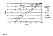
- the figure 3 illustrates the accumulation of mixing efficiencies. If the mixing efficiency in the torus ( ⁇ torus ) is 50% and the torus outlet mixing efficiency ( ⁇ swirl ) on the 80% predistribution plateau, an overall mixing efficiency greater than 90 is obtained. %.
- the mixing device according to the invention has a high fluid mixing efficiency thanks to the combination of the annular mixing chamber placed on the predistribution plate and the predistribution plate. This arrangement allows a continuity of the rotational flow of the fluids on the predistribution plate. As a result, fluid mixing continues to occur on said tray.
- the theoretical efficiency is calculated using a mixing efficiency of 80% on the predistribution plate.
- the overall measured thermal efficiency is, in all cases, greater than 99.7%, the difference at 100% being due to the noise of the measurement (not significant).
- An example of sizing of the mixing device is reported. It is based on a reaction chamber diameter of 2.5 m.
- the density of the liquid phase is 800 kg.m- 3 , and that of the gas is 10 kg.m -3 .
- the flow rates of liquid and gas leaving the first catalytic bed are respectively 0.11 and 0.49 m 3 .s -1 .
- the flow rate of quenching liquid injected into the vertical collection line via an injection means is 0.03 m 3 .s -1 .
- the height of the collection space (H1) is 0.1 m so as to generate a negligible pressure drop in this zone.
- the vertical collection pipe has a diameter of 0.4 m.
- the quenching fluid injection means has a diameter of 0.12 m.
- the diameter of the annular mixing chamber is 0.3 m, for a linear length of 3.1 m.
- the space between the reactor chamber and the annular mixing chamber is 0.03 m.
- Four central chimneys are arranged square in the middle of the perforated plate of the predistribution plate. These chimneys have a diameter of 0.3 m and a height of 0.25 m.
- the predistribution tray is perforated by holes 1 cm in diameter at a triangular perforation pitch of 6.4 cm. Under the perforated plate is positioned a distributor tray with chimneys. The distance between the predistribution perforated plate and the distributor plate is 0.25 m.
- the pressure drop of the quenching device is estimated according to equation (3) at 16 16 000 Pa.
- the liquid guard height on the perforated plate is 15 cm, according to the observations made on the cold model.
- the device according to the invention makes it possible to ensure good mixing at the quench toroid output.
- the theoretical efficiency of the quenching toroid is according to equation (2) of 54%. According to the calculations and measurements made on cold model, this is sufficient to ensure a total effectiveness of the device close to 100%.
- the size of the device according to the invention delimited by the support grid of the catalyst bed (element 3 on the figure 1 ) and by the predistribution plateau (element 11 on the figure 1 ) is about 0.5 m. It is about 0.75 m if we add the size of the distribution tray (element 12) located below the predistribution plate.
- the mixing device described in the patent application FR-A-2824495 also uses a catalyst bed support grid and a predistribution plate located just above a distribution tray.
- the size of this device, calculated between the catalytic bed support grid and predistribution plate is about 0.88 m.
- the mixing device according to the invention allows a space saving of 76% compared to the device described in the application. FR-A-2824495 .
- the 0.38 m that has been gained over the prior art device can be used in the catalyst beds.
- the compact mixing device according to the invention also makes it possible to improve the performance of a reactor by increasing the amount of catalyst in the catalytic beds.
Abstract
Description
La présente invention concerne un dispositif compact de mélange de fluides dans un réacteur à écoulement descendant et son utilisation pour la réalisation de réactions exothermiques. L'invention concerne également un réacteur comprenant un dispositif compact de mélange. L'invention s'applique dans le domaine des réactions exothermiques et plus particulièrement aux réactions d'hydrotraitement, de d'hydrodésulfuration, d'hydrogéazotation, d'hydrocraquage, d'hydrogénation et d'hydrodéaromatisation.The present invention relates to a compact device for mixing fluids in a downflow reactor and its use for carrying out exothermic reactions. The invention also relates to a reactor comprising a compact mixing device. The invention applies in the field of exothermic reactions and more particularly to hydrotreatment, hydrodesulphurization, hydrogenation, hydrocracking, hydrogenation and hydrodearomatization reactions.
Les réactions exothermiques réalisées en raffinage et/ou en pétrochimie nécessitent d'être refroidies par un fluide additionnel pour éviter un emballement thermique du réacteur dans lequel elles sont effectuées. Il est également nécessaire de garder un gradient de température homogène au sein du réacteur afin d'éviter l'existence de points chauds dans le lit de catalyseur. Ces points chauds peuvent diminuer prématurément l'activité du catalyseur. Ils conduisent également à des réactions non sélectives. Il est donc important de disposer d'au moins une chambre de mélange dans un réacteur qui permette une répartition homogène en température des fluides et un refroidissement des fluides réactionnels à une température désirée.The exothermic reactions carried out in refining and / or in petrochemistry need to be cooled by an additional fluid to prevent thermal runaway of the reactor in which they are carried out. It is also necessary to keep a homogeneous temperature gradient within the reactor in order to avoid the existence of hot spots in the catalyst bed. These hot spots can prematurely decrease the activity of the catalyst. They also lead to non-selective reactions. It is therefore important to have at least one mixing chamber in a reactor which allows a uniform temperature distribution of the fluids and a cooling of the reaction fluids to a desired temperature.
Pour effectuer cette homogénéisation l'homme de l'art est souvent conduit à utiliser un agencement spécifique d'internes souvent complexes comportant une introduction du fluide de trempe la plus homogène possible dans la section du réacteur. Cette injection s'effectue en aval de la chambre de mélange soit par des systèmes multitrous tels que ceux décrits par exemple dans les documents de brevets
Il est également connu par la demande de brevet
Certains dispositifs actuels permettent de réduire cet encombrement. Par exemple, les brevets
La présente invention a donc pour objet de palier un ou plusieurs des inconvénients de l'art antérieur en proposant un dispositif compact de mélange. Le dispositif selon l'invention permet un gain substantiel en terme d'encombrement du réacteur et assure un bon mélange des fluides et une bonne homogénéité en température.The present invention therefore aims to overcome one or more of the disadvantages of the prior art by providing a compact mixing device. The device according to the invention allows a substantial gain in terms of the size of the reactor and ensures a good mixture of fluids and a good temperature homogeneity.
Un premier objet de l'invention est de fournir un dispositif compact de mélange de fluides dans un réacteur à écoulement descendant.A first object of the invention is to provide a compact device for mixing fluids in a downflow reactor.
Un autre objet de l'invention concerne l'utilisation d'un dispositif compact de mélange de fluides dans un réacteur à écoulement descendant pour la réalisation de réactions exothermiques.Another object of the invention relates to the use of a compact device for mixing fluids in a downflow reactor for carrying out exothermic reactions.
Un autre objet de l'invention concerne un réacteur comprenant un dispositif compact de mélange de fluides.Another object of the invention relates to a reactor comprising a compact device for mixing fluids.
Un autre objet de l'invention concerne l'utilisation d'un réacteur comprenant un dispositif compact de mélange de fluides pour la réalisation de réactions exothermiques.Another object of the invention relates to the use of a reactor comprising a compact device for mixing fluids for carrying out exothermic reactions.
Selon un premier aspect, l'invention concerne un dispositif compact de mélange de fluides dans un réacteur à écoulement descendant comprenant :
- au moins un moyen de collecte sensiblement horizontal pourvu d'une conduite de collecte verticale pour recevoir les fluides,
- au moins un moyen d'injection placé dans ladite conduite de collecte,
- une chambre de mélange annulaire située en aval du moyen de collecte dans le sens de circulation des fluides, ladite chambre comprenant une extrémité d'entrée directement reliée à ladite conduite de collecte et une extrémité de sortie pour le passage des fluides, ladite extrémité de sortie est positionnée suivant la direction radiale de l'enceinte du réacteur,et
- un plateau de prédistribution horizontal comprenant au moins une cheminée, ledit plateau situé en aval de ladite chambre à une distance d2, dans le sens de circulation des fluides.
- at least one substantially horizontal collection means provided with a vertical collection line for receiving the fluids,
- at least one injection means placed in said collection line,
- an annular mixing chamber located downstream of the collection means in the fluid flow direction, said chamber comprising an inlet end directly connected to said collection pipe and an outlet end for the passage of the fluids, said outlet end is positioned in the radial direction of the reactor enclosure, and
- a horizontal predistribution plate comprising at least one chimney, said plate located downstream of said chamber at a distance d2, in the direction of circulation of the fluids.
Selon une variante de l'invention, le moyen d'injection se situe au niveau de l'extrémité d'entrée de la chambre de mélange annulaire.According to a variant of the invention, the injection means is located at the inlet end of the annular mixing chamber.
Selon une autre variante de l'invention, la distance d2 entre le plateau de prédistribution et la chambre de mélange annulaire est comprise entre 0 et 100 mm. De manière préférée, cette distance est comprise 0,25 et 100 mm. De manière encore plus préférée, cette distance est comprise 0,5 et 5 mm.According to another variant of the invention, the distance d2 between the predistribution plate and the annular mixing chamber is between 0 and 100 mm. Preferably, this distance is between 0.25 and 100 mm. Even more preferably, this distance is between 0.5 and 5 mm.
Selon une autre variante de l'invention, la distance d2 entre le plateau de prédistribution et la chambre de mélange annulaire est égale à 0 mm, la chambre de mélange annulaire étant en contact avec le plateau de prédistribution.According to another variant of the invention, the distance d2 between the predistribution plate and the annular mixing chamber is equal to 0 mm, the annular mixing chamber being in contact with the predistribution plate.
Selon une autre variante de l'invention, la chambre de mélange annulaire est positionnée à la périphérie de l'enceinte du réacteur.According to another variant of the invention, the annular mixing chamber is positioned at the periphery of the reactor enclosure.
Selon une autre variante de l'invention, la chambre de mélange annulaire est positionnée à une distance d1 de l'enceinte du réacteur, la distance d1 variant de 0,5% à 25% du diamètre du réacteur.According to another variant of the invention, the annular mixing chamber is positioned at a distance d 1 from the chamber of the reactor, the distance d 1 ranging from 0.5% to 25% of the reactor diameter.
Selon une autre variante de l'invention, le diamètre d de la chambre de mélange annulaire est compris entre 0,05 et 0,5 m. De manière préféré le diamètre est compris entre 0,1 et 0,3 m. De manière encore plus préférée, il est compris entre 0,15 et 0,25 m.According to another variant of the invention, the diameter d of the annular mixing chamber is between 0.05 and 0.5 m. Preferably the diameter is between 0.1 and 0.3 m. Even more preferably, it is between 0.15 and 0.25 m.
Selon une autre variante de l'invention, la longueur de la chambre de mélange annulaire est comprise entre 90 et 270 degrés. Préférentiellement, elle est comprise entre 100 et 250 degrés. De manière encore plus préférée, elle est comprise entre 130 et 200 degrés.According to another variant of the invention, the length of the annular mixing chamber is between 90 and 270 degrees. Preferably, it is between 100 and 250 degrees. Even more preferably, it is between 130 and 200 degrees.
Selon un second aspect, l'invention concerne l'utilisation du dispositif compact de mélange pour la réalisation de réactions exothermiques.According to a second aspect, the invention relates to the use of the compact mixing device for carrying out exothermic reactions.
Selon un troisième aspect, l'invention concerne un réacteur de forme allongée le long d'un axe sensiblement vertical dans lequel on fait circuler du haut vers le bas dudit réacteur au moins un fluide réactionnel à travers au moins un lit de catalyseur, ledit réacteur comprenant en aval du lit de catalyseur dans le sens de circulation dudit fluide réactionnel au moins un dispositif compact de mélange.According to a third aspect, the invention relates to an elongated reactor along a substantially vertical axis in which at least one reaction fluid is circulated from the top to the bottom of said reactor through at least one catalyst bed, said reactor comprising downstream of the catalyst bed in the direction of circulation of said reaction fluid at least one compact mixing device.
Selon une variante de l'invention, le réacteur comprend en outre, un plateau de distribution sensiblement horizontal positionné en aval du dispositif compact de mélange dans le sens de circulation des fluides.According to a variant of the invention, the reactor further comprises a substantially horizontal distribution plate positioned downstream of the compact mixing device in the direction of circulation of the fluids.
Selon une autre variante de l'invention, le réacteur comprend en outre un deuxième lit de catalyseur situé en aval du dispositif compact de mélange et du plateau de distribution.According to another variant of the invention, the reactor further comprises a second catalyst bed located downstream of the compact mixing device and the distribution plate.
Selon un quatrième aspect de l'invention, l'invention concerne l'utilisation pour la réalisation de réactions exothermiques d'un réacteur de forme allongée le long d'un axe sensiblement vertical dans lequel on fait circuler du haut vers le bas dudit réacteur au moins un fluide réactionnel à travers au moins un lit de catalyseur, ledit réacteur comprenant en aval du lit de catalyseur dans le sens de circulation dudit fluide réactionnel au moins un dispositif compact de mélange.According to a fourth aspect of the invention, the invention relates to the use for carrying out exothermic reactions of an elongated reactor along a substantially vertical axis in which the reactor is circulated from the top to the bottom of the reactor. minus one reaction fluid through at least one catalyst bed, said reactor comprising downstream of the catalyst bed in the direction of circulation of said reaction fluid at least one compact mixing device.
-
La
figure 1 représente une coupe axiale d'un réacteur multi-lit à écoulement descendant comprenant le dispositif compact de mélange selon l'invention. La flèche en gras représente le sens d'écoulement des fluides dans le réacteur.Thefigure 1 represents an axial section of a downflow multi-bed reactor comprising the compact mixing device according to the invention. The arrow in bold represents the flow direction of the fluids in the reactor. -
La
figure 2 représente une vue du dessus du dispositif compact de mélange selon la coupe représentée par la ligne A-A en pointillé.Thefigure 2 represents a top view of the compact mixing device according to the section represented by the dotted line AA. -
La
figure 3 représente l'efficacité totale de mélange du dispositif selon l'invention en fonction de l'efficacité de mélange mesurée sur le plateau de prédistribution (abscisse ηswirl) et pour différente efficacité de la chambre de mélange annulaire (ηtore).Thefigure 3 represents the total mixing efficiency of the device according to the invention as a function of the mixing efficiency measured on the predistribution plate (abscissa η swirl ) and for different efficiency of the annular mixing chamber (η torus ).
Le dispositif compact de mélange selon l'invention est utilisé dans un réacteur dans lequel s'effectuent des réactions exothermiques telles que des réactions d'hydrotraitement, de d'hydrodésulfuration, d'hydrogéazotation, d'hydrocraquage, d'hydrogénation et d'hydrodéaromatisation. Le réacteur a une forme allongée le long d'un axe sensiblement vertical. On fait circuler du haut vers le bas dudit réacteur au moins un fluide réactionnel (ou fluide de process, selon la terminologie anglo-saxonne) à travers au moins un lit de catalyseur. En sortie du lit, le fluide réactionnel est recueilli puis mélangé à un fluide de trempe (ou fluide de quench, selon la terminologie anglo-saxonne) dans le dispositif compact selon l'invention avant d'être distribué au lit de catalyseur situé en aval du plateau de distribution. L'aval et l'amont sont définis par rapport au sens de l'écoulement du fluide réactionnel.The compact mixing device according to the invention is used in a reactor in which exothermic reactions such as hydrotreatment, hydrodesulfurization, hydrogenation, hydrocracking, hydrogenation and hydrodearomatization reactions take place. . The reactor has an elongate shape along a substantially vertical axis. From the top to the bottom of said reactor is circulated at least one reaction fluid (or process fluid, according to the English terminology) through at least one catalyst bed. On leaving the bed, the reaction fluid is collected and then mixed with a quenching fluid (or quenching fluid, according to the English terminology) in the compact device according to the invention before being distributed to the downstream catalyst bed. of the distribution tray. The downstream and the upstream are defined with respect to the flow direction of the reaction fluid.
Le fluide réactionnel peut être un gaz ou un liquide ou un mixte contenant du liquide ou du gaz; cela dépend du type de réaction effectuée dans le réacteur. Le fluide réactionnel traversant le lit de catalyseur amont est collecté par un moyen de collecte sensiblement horizontal (5) pourvu d'une conduite de collecte sensiblement verticale (7) (cf.
La conduite de collecte verticale (7) débouche dans la chambre de mélange annulaire (9) au niveau de l'extrémité d'entrée de ladite chambre. Cette conduite dirige l'écoulement du fluide réactionnel et du fluide de trempe dans ladite chambre. Le diamètre de la conduite verticale (7) est choisi de manière à limiter les pertes de charge. Il sera donc choisi de manière à limiter la vitesse d'écoulement, dans ladite conduite de collecte, du (ou des) fluide(s) réactionnel(s) provenant du lit de catalyseur situé en amont du moyen de collecte. Préférentiellement la vitesse desdits fluides sera comprise entre 2 et à 5 m.s-1.The vertical collection line (7) opens into the annular mixing chamber (9) at the inlet end of said chamber. This conduit directs the flow of reaction fluid and quench fluid into said chamber. The diameter of the vertical pipe (7) is chosen so as to limit the pressure drops. It will therefore be chosen so as to limit the flow rate, in said collection line, of (or) reaction fluid (s) from the catalyst bed located upstream of the collection means. Preferably, the speed of said fluids will be between 2 and 5 ms -1 .
Le fluide de trempe est injecté par un moyen d'injection (8) dans la conduite de collecte verticale. L'injection s'effectue perpendiculairement au sens d'écoulement du fluide réactionnel dans la conduite de collecte. Le moyen d'injection utilisé est bien connu de l'homme du métier. Il peut être un piquage latéral, ou une buse ou araignées, ou une rampe de buses, etc.The quenching fluid is injected by an injection means (8) into the vertical collection line. The injection is carried out perpendicularly to the flow direction of the reaction fluid in the collection line. The injection means used is well known to those skilled in the art. It can be a lateral stitching, or a nozzle or spiders, or a nozzle ramp, etc.
Le moyen d'injection se situe à n'importe quelle hauteur dans la conduite de collecte à partir de l'ouverture (6). Préférentiellement le moyen d'injection se situe au niveau de la connexion de la conduite de collecte avec l'extrémité d'entrée de la chambre de mélange annulaire.The injection means is located at any height in the collection line from the opening (6). Preferably the injection means is at the connection of the collection line with the inlet end of the annular mixing chamber.
Le fluide de trempe peut être liquide ou gazeux ou mixte contenant du liquide ou du gaz. Par exemple le fluide de trempe peut être de l'hydrogène.The quenching fluid may be liquid or gaseous or mixed containing liquid or gas. For example, the quenching fluid may be hydrogen.
La chambre de mélange annulaire (9) permet le mélange du fluide réactionnel avec le fluide de trempe. Ladite chambre a une forme toroïdale incomplète. Elle est formée par un tube recourbé de façon à former un arc de cercle. Elle comprend donc deux extrémités distinctes l'une de l'autre: une extrémité dite d'entrée et une extrémité dite de sortie (10), opposée à l'extrémité d'entrée. L'extrémité d'entrée est reliée à la conduite de collecte et l'extrémité de sortie est ouverte et permet au mélange de fluides de s'écouler sur le plateau de prédistribution. L'extrémité de sortie (10) est positionnée suivant la direction radiale de l'enceinte du réacteur (1). Ainsi les fluides sortants de la section d'ouverture (10) sont projetés dans la direction tangentielle de la section du réacteur (1). Cette disposition permet de maintenir un écoulement rotatif du mélange des fluides sur le plateau de prédistribution (11). Grâce à cet écoulement rotatif, le ou les fluides réactionnels et le fluide de trempe peuvent continuer à se mélanger sur le plateau de prédristibution. Le diamètre et la longueur de la chambre de mélange annulaire (9) sont choisis de manière à garantir un bon mélange entre l'écoulement issu du lit (2) et le fluide de trempe, tout en limitant la perte de charge dans la conduite de collecte et l'encombrement dans le réacteur. La longueur de la chambre de mélange annulaire est définie par l'angle formé par les plans passant par les deux extrémités de ladite chambre. La longueur de ladite chambre est comprise entre 90 et 270 degrés. De manière préférée, la longueur de ladite chambre est comprise entre 100 et 200 degrés, 100 et 250 degrés, de manière encore plus préférée 100 et 180 degrés, 130 et 200 degrés. Selon un mode préférentiel, ladite chambre selon l'invention a la forme d'un tore ouvert; la section de ladite chambre est un cercle. Dans un autre mode de réalisation de l'invention, la section de ladite chambre peut être ovale ou rectangulaire. Quelle que soit la forme de la section de la chambre de mélange annulaire, le diamètre (ou la hauteur) d de ladite chambre sera choisie de manière à limiter au maximum la perte de charge et de manière à limiter l'encombrement spatial dans le réacteur. Ce diamètre d est comprise entre 0,05 et 0,5 m, plus préférentiellement entre 0,1 et 0,3 m, préférentiellement entre 0,15 et 0,4 m, encore plus préférentiellement entre 0,15 et 0,25 m, encore plus préférentiellement entre 0,1 et 0,35 m. La perte de charge du dispositif de mélange selon l'invention dépend uniquement de la hauteur d de la chambre annulaire de mélange. Cette perte de charge suit une loi classique de perte de charge et peut être définie par l'équation suivante: 
où ΔP est la perte de charge, pm la densité moyenne du mélange gaz+liquide dans la chambre de mélange annulaire, Vm la vitesse moyenne du mélange gaz+liquide et x est le coefficient de perte de charge associé au dispositif de mélange. Ce coefficient a été mesuré à une valeur de 2 quelles que soient les conditions d'écoulement. Selon un mode préféré de réalisation de l'invention, le diamètre sera le plus petit possible afin de limiter l'encombrement de la chambre de mélange annulaire sur la plaque de prédistribution et d'avoir une efficacité de mélange la plus grande en sortie de ladite chambre. Pour ces raisons, il sera préféré d'utiliser le plus petit diamètre d possible permettant de respecter un éventuel critère de perte de charge maximale. La gamme préférentielle de perte de charge lors du dimensionnement de dispositifs industriels est 0,05 bars < ΔPmax < 0,5 bars (1 bar = 105 Pa).The annular mixing chamber (9) allows mixing of the reaction fluid with the quenching fluid. Said chamber has an incomplete toroidal shape. It is formed by a tube curved so as to form a circular arc. It therefore comprises two ends that are distinct from each other: a so-called input end and a so-called output end (10), opposite to the input end. The inlet end is connected to the collection line and the outlet end is open and allows the fluid mixture to flow on the predistribution plate. The outlet end (10) is positioned in the radial direction of the reactor vessel (1). Thus, the outgoing fluids of the opening section (10) are projected in the tangential direction of the section of the reactor (1). This arrangement makes it possible to maintain a rotational flow of the mixture of fluids on the predistribution plate (11). Due to this rotary flow, the reaction fluid (s) and the quenching fluid can continue to mix on the predisposition tray. The diameter and the length of the annular mixing chamber (9) are chosen so as to ensure good mixing between the flow from the bed (2) and the quenching fluid, while limiting the pressure drop in the collection line and the bulk in the reactor. The length of the annular mixing chamber is defined by the angle formed by the planes passing through the two ends of said chamber. The length of said chamber is between 90 and 270 degrees. Preferably, the length of said chamber is between 100 and 200 degrees, 100 and 250 degrees, even more preferably 100 and 180 degrees, 130 and 200 degrees. According to a preferred embodiment, said chamber according to the invention has the shape of an open torus; the section of said chamber is a circle. In another embodiment of the invention, the section of said chamber may be oval or rectangular. Whatever the shape of the section of the annular mixing chamber, the diameter (or the height) d of said chamber will be chosen so as to minimize the pressure drop and so as to limit the space requirement in the reactor . This diameter d is between 0.05 and 0.5 m, more preferably between 0.1 and 0.3 m, preferentially between 0.15 and 0.4 m, even more preferably between 0.15 and 0.25 m. more preferably between 0.1 and 0.35 m. The pressure drop of the mixing device according to the invention depends solely on the height d of the annular mixing chamber. This pressure drop follows a conventional law of pressure loss and can be defined by the following equation:
where ΔP is the pressure drop, p m is the average density of the gas + liquid mixture in the annular mixing chamber, V m is the average speed of the gas + liquid mixture and x is the coefficient of pressure loss associated with the mixing device. This coefficient was measured at a value of 2 regardless of the flow conditions. According to a preferred embodiment of the invention, the diameter will be as small as possible in order to limit the size of the annular mixing chamber on the predistribution plate and to have the greatest mixing efficiency at the outlet of said bedroom. For these reasons, it will be preferred to use the smallest diameter d possible to meet a possible criterion of maximum pressure drop. The preferred pressure drop range when dimensioning industrial devices is 0.05 bar <ΔP max <0.5 bar (1 bar = 10 5 Pa).
Les fluides ont un mouvement rotationnel (ou de swirling selon la terminologie anglo-saxonne) dans la chambre de mélange annulaire (9). Ce mouvement favorise le mélange et l'homogénéité en température des fluides réactionnels et du fluide de trempe.The fluids have a rotational movement (or swirling according to the English terminology) in the annular mixing chamber (9). This movement promotes mixing and temperature homogeneity of the reaction fluids and the quenching fluid.
La chambre de mélange annulaire est positionnée à la périphérie de l'enceinte du réacteur et en amont du plateau de prédistribution dans le sens d'écoulement des fluides. Ce positionnement de ladite chambre permet de maximiser sa longueur et d'obtenir un gain de place dans le réacteur. La chambre de mélange annulaire ayant une forme courbée, elle longe l'enceinte du réacteur à une distance d1. Afin que le dispositif compact de mélange selon l'invention encombre le moins possible l'espace du réacteur, la distance d1 sera comprise entre 0,5% et 25% du diamètre du réacteur, préférentiellement entre 0,5% et 10% du diamètre du réacteur, encore plus préférentiellement entre 1 % et 5% du diamètre du réacteur.The annular mixing chamber is positioned at the periphery of the reactor chamber and upstream of the predistribution plate in the flow direction of the fluids. This positioning of said chamber makes it possible to maximize its length and to obtain a saving of space in the reactor. The annular mixing chamber having a curved shape, it runs along the enclosure of the reactor at a distance d1. So that the compact mixing device according to the invention encumbers as little as possible the reactor space, the distance d1 will be between 0.5% and 25% of the reactor diameter, preferably between 0.5% and 10% of the reactor diameter, more preferably between 1% and 5% of the reactor diameter.
Dans un mode préféré de réalisation, ladite chambre est en contact direct avec ledit plateau. Dans cette configuration, la chambre de mélange annulaire est donc posée directement sur le plateau de prédistribution. Dans un autre mode de réalisation, ladite chambre se situe à une distance d2 du plateau de prédistribution. Dans ce cas, ladite chambre sera fixée sur le plateau par des moyens de fixations bien connus de l'homme du métier tels que des pieds creux. Ces pieds seront positionnés dans le sens de l'écoulement du mélange. La distance d2 varie entre 0 et 100 mm, plus préférentiellement entre 0,25 et 100 mm, plus préférentiellement entre 0 et 50 mm, encore plus préférentiellement 0,5 et 30 mm, encore plus préférentiellement entre 0,5 et 5 mm.In a preferred embodiment, said chamber is in direct contact with said tray. In this configuration, the annular mixing chamber is placed directly on the predistribution plate. In another embodiment, said chamber is at a distance d2 from the predistribution plate. In this case, said chamber will be fixed on the plate by fastening means well known to those skilled in the art such as hollow feet. These feet will be positioned in the direction of the flow of the mixture. The distance d2 varies between 0 and 100 mm, more preferably between 0.25 and 100 mm, more preferably between 0 and 50 mm, more preferably between 0.5 and 30 mm, more preferably between 0.5 and 5 mm.
Le positionnement de la chambre de mélange annulaire en périphérie du réacteur et amont du plateau de prédistribution permet également un écoulement tangentiel du mélange des fluides en dessus ou sur de plateau de prédistribution, suivant le mode de réalisation de l'invention. Cet écoulement tangentiel au dessus dudit plateau permet d'optimiser l'efficacité du mélange. En effet, le mélange entre le fluide réactionnel et le fluide de trempe continue de s'effectuer au niveau du plateau de prédistribution contrairement aux dispositifs de mélange décrits dans l'art antérieur dans lesquels le mélange ne se fait que dans la chambre de trempe. Ainsi l'efficacité du dispositif compact de mélange selon l'invention est augmentée. On obtient un mélange homogène en température et en concentration des deux fluides sur le plateau de pré-distribution (11).The positioning of the annular mixing chamber at the periphery of the reactor and upstream of the predistribution plate also allows a tangential flow of the mixture of fluids above or on a predistribution plate, according to the embodiment of the invention. This tangential flow above said plate optimizes the efficiency of the mixture. Indeed, the mixing between the reaction fluid and the quenching fluid continues to take place at the predistribution plate in contrast to the mixing devices described in the prior art in which the mixing is only in the quenching chamber. Thus the efficiency of the compact mixing device according to the invention is increased. A homogeneous mixture of temperature and concentration of the two fluids is obtained on the pre-distribution plate (11).
Le plateau de pré-distribution (11) situé sous la chambre de mélange annulaire (9) se compose d'une plaque perforée et de une ou plusieurs cheminées (13). Les cheminées (13) sont situées de manière préférée au centre du plateau de prédistribution pour ne pas gêner l'écoulement rotatif du mélange de fluides sur ledit plateau. Le design de cette plaque est optimisé de façon à diminuer la perte de charge et à produire une garde liquide de quelques centimètres. A titre d'exemple non limitatif, le plateau de pré-distribution est perforé par des trous de 10 mm suivant un pas triangulaire. Le plateau de prédistribution s'étend radialement sur toute la surface du réacteur et est disposé dans le plan perpendiculaire à l'axe longitudinal de l'enceinte. Il permet une première séparation du mélange, le liquide s'écoule au travers desdits trous et le gaz s'écoule au travers desdites cheminées.The pre-distribution plate (11) located under the annular mixing chamber (9) consists of a perforated plate and one or more chimneys (13). The stacks (13) are preferably located in the center of the predistribution plate so as not to impede the rotational flow of the fluid mixture on said tray. The design of this plate is optimized to reduce the pressure drop and produce a liquid guard of a few centimeters. By way of non-limiting example, the pre-distribution plate is perforated by holes of 10 mm in a triangular pitch. The predistribution plate extends radially over the entire surface of the reactor and is disposed in the plane perpendicular to the longitudinal axis of the enclosure. It allows a first separation of the mixture, the liquid flows through said holes and the gas flows through said chimneys.
Selon un mode de réalisation de l'invention, le dispositif selon l'invention comprend en outre un plateau de distribution qui permet d'optimiser la distribution du fluide réactionnel refroidi sur le lit catalytique situé en aval. Ces plateaux de distribution sont bien connus de l'homme du métier. On pourra se référer à la demande de brevet
Par rapport aux dispositifs décrits dans l'art antérieur, le dispositif compact selon la présente invention offre les avantages suivants :
- une efficacité de mélange accrue grâce à l'écoulement rotatif dans la chambre de mélange annulaire et sur ou au niveau du plateau de prédistribution,
- une simplicité de mise en oeuvre,
- une compacité accrue du fait de l'emplacement de la chambre de mélange annulaire très rapproché du plateau de prédistribution, et de l'injection du fluide de trempe au niveau de ladite chambre.
- une faible perte de charge induite due à l'absence d'interne dans la chambre de mélange annulaire.
- increased mixing efficiency through rotational flow in the annular mixing chamber and at or at the pre-distribution plate,
- simplicity of implementation,
- increased compactness due to the location of the annular mixing chamber very close to the predistribution plate, and the injection of the quenching fluid at said chamber.
- a small loss of induced load due to the absence of internal in the annular mixing chamber.
La
La chambre de mélange (9) selon l'invention, illustrée sur la
Dans les exemples ci-dessous, on emploie indifféremment les termes "tore" ou "chambre de mélange" ou "chambre de mélange annulaire" pour désigner la chambre de mélange annulaire selon l'invention.In the examples below, the terms "torus" or "mixing chamber" or "annular mixing chamber" are used interchangeably to designate the annular mixing chamber according to the invention.
On simule l'écoulement de deux fluides dans la chambre de mélange annulaire selon l'invention en utilisant un logiciel de mécanique des fluides (Fluent 6.3, développé par la société ANSYS Inc, Canonburg, USA). Les simulations numériques ont porté sur l'analyse des phénomènes de mélange:
- (a) dans la chambre de mélange annulaire,
- (b) en sortie de ladite chambre.
- (a) in the annular mixing chamber,
- (b) at the outlet of said chamber.
Les caractéristiques des différentes chambres de mélange annulaires testées et les conditions expérimentales de simulation sont présentées dans le tableau 1, ci-dessous.The characteristics of the various annular mixing chambers tested and the experimental simulation conditions are presented in Table 1, below.
Pour effectuer ces simulations, on se place dans le cas le plus défavorable, c'est à dire dans le cas où les fluides (eau liquide et azote gazeux) ne sont pas mélangés du tout à l'entrée du tore. On impose donc au logiciel la configuration suivante: les fluides sont alimentés à deux températures clairement distinctes T1 et T2 en entrée du tore, de telle manière que la moitié de la section d'entrée du tore est à la température T1 et l'autre moitié à la température T2.To carry out these simulations, one places oneself in the most unfavorable case, ie in the case where the fluids (liquid water and nitrogen gas) are not mixed at all at the entrance of the torus. We therefore impose on the software the following configuration: the fluids are fed at two clearly distinct temperatures T1 and T2 at the inlet of the torus, so that half of the inlet section of the torus is at temperature T1 and the other half at temperature T2.
Les caractéristiques des chambres de mélange annulaires testées sont résumées dans le tableau 1:
(m3 .h-1)
gaz (m3 h-1)
T1 (K)
T2 (K)
(m 3 .h -1 )
gas (m 3 h -1 )
T1 (K)
T2 (K)
La distribution de températures calculée en sortie du tore par le logiciel de simulation, est utilisée pour estimer l'efficacité de mélange du tore. Cette efficacité est définie par la relation suivante : 
ou η est l'efficacité du mélange, σ est l'écart type des températures et ΔTmax l'écart maximal entre les températures, soit la valeur absolue de (T2-T1). Les multiples simulations ont mis en évidence que le mélange théorique dans le tore suit globalement une loi de type: 
ou x est la distance linéaire parcourue dans le tore, U est la vitesse du liquide dans le tore et d le diamètre du tore.The temperature distribution calculated at the output of the torus by the simulation software is used to estimate the mixing efficiency of the torus. This efficiency is defined by the following relation:
where η is the efficiency of the mixture, σ is the standard deviation of the temperatures and ΔTmax is the maximum difference between the temperatures, ie the absolute value of (T2-T1). Multiple simulations have shown that the theoretical mixture in the torus generally follows a law of the type:
where x is the linear distance traveled in the torus, U is the velocity of the liquid in the torus and d is the diameter of the torus.
Les résultats obtenus des différentes simulations sont présentés dans le tableau 2 ci-dessous. Les efficacités de mélange sont calculées à mi longueur de la chambre de mélange (U2) et en sortie de la chambre de mélange.
L'efficacité de mélange (selon équation 1) généré à mi longueur de la chambre de mélange annulaire ou en sortie de ladite chambre est supérieure à 80 %. Dans certaines configurations de chambre, cette efficacité est même égale à 99%. Ceci signifie qu'on obtient un très bon mélange de fluides dans la chambre selon notre invention et une excellente homogénéisation des fluides en température.The mixing efficiency (according to equation 1) generated halfway through the annular mixing chamber or at the outlet of said chamber is greater than 80%. In some chamber configurations, this efficiency is even equal to 99%. This means that a very good mixture of fluids is obtained in the chamber according to our invention and excellent homogenization of the fluids in temperature.
On cherche à déterminer l'efficacité du mélange généré dans le dispositif de mélange selon l'invention au niveau du plateau de prédistribution. Pour cela, on simule l'écoulement des fluides sur le plateau de prédistribution avec le logiciel de mécanique des fluides (Fluent 6.3, développé par la société ANSYS Inc, Canonburg, USA). Les caractéristiques des différents dispositifs de mélange et les conditions expérimentale testées sont résumées dans le tableau 3. Les simulations sont réalisées en écoulement monophasique, c'est à dire en l'absence de phase gaz. Elles sont donc représentatives du cas où le fluide de trempe est du liquide, et où seules les phases liquides doivent être mélangées.
Pour étudier de l'efficacité de mélange au niveau du plateau de prédistribution dans le dispositif selon l'invention, on divise la section du tore en deux zones de même surface : l'une étant à une température T1 et l'autre à une température T2. Cette condition expérimentale correspond au cas le plus défavorable, c'est à dire au cas où il n'y a pas eu de mélange des deux fluides dans la chambre de mélange annulaire. On mesure, dans ces conditions, uniquement l'efficacité de l'écoulement rotatif sur le plateau de prédistribution.To study mixing efficiency at the level of the predistribution plate in the device according to the invention, the section of the torus is divided into two zones of the same surface: one being at a temperature T1 and the other at a temperature T2. This experimental condition corresponds to the most unfavorable case, ie in the case where there has been no mixing of two fluids in the annular mixing chamber. Under these conditions, only the efficiency of the rotary flow on the predistribution plate is measured.
Les résultats obtenus sont présentés dans le tableau 4.
L'efficacité de mélange (selon équation 1) généré en sortie de tore sur la plaque de prédistribution est toujours supérieure ou égale à 80%. Ceci signifie que l'écoulement rotatif généré participe fortement au mélange des fluides dans la gamme de fonctionnement étudiée par simulation.The mixing efficiency (according to equation 1) generated at the torus outlet on the predistribution plate is always greater than or equal to 80%. This means that the generated rotational flow strongly participates in the mixing of the fluids in the operating range studied by simulation.
En considérant que les efficacités de mélange dans le tore et en sortie de tore sur le plateau de prédistribution peuvent être cumulées, l'efficacité totale de mélange du dispositif selon l'invention s'exprime par la formule suivante: 
La
The
A titre d'exemple non limitatif, des mesures d'efficacité de mélange ont été réalisées avec un dispositif de mélange selon l'invention disposé dans réacteur. Les conditions expérimentales sont les suivantes :
- Un réacteur de diamètre de 480 mm est découpé en deux secteurs identiques dans sa partie supérieure. Les deux secteurs sont alimentés à l'identique en gaz (air) et en liquide (eau). La hauteur des secteurs est de 500 mm. Les deux secteurs sont alimentés par des fluides à des températures différentes T1 (283 K) et T2 (330 K). Sous le lit granulaire, porté par la grille support est disposé le baffle de collecte. La distance entre la grille support et le baffle de collecte est égale à 100 mm. La conduite de collecte verticale est de hauteur 150 mm et de diamètre 100 mm. Les caractéristiques structurelles des différents tores de mélange testés sont présentées dans le tableau 5. Le tube d'injection du fluide de trempe (eau) a un diamètre de 20 mm. Le plateau de prédistribution est muni d'une cheminée centrale de diamètre 4 cm et de hauteur 25 cm. Le plateau de prédistribution est perforé par des trous de 1 cm de diamètre selon un pas triangulaire de 6,4 cm. Sous le plateau de prédistribution est positionné un plateau distributeur de type plateaux à cheminées perforées. En aval du plateau de distribution, dans le sens d'écoulement des fluides est positionné un lit de billes inertes afin de représenter un lit catalytique. A 3 cm sous les premières couches de billes inertes sont positionnés 6 thermocouples répartis sur la section de colonne. L'efficacité du mélange du dispositif de mélange selon l'invention est calculée à partir des relevés de températures fournis par les thermocouples, selon l'équation (2). Pour cela, l'écart type des températures relevées est calculé préalablement.
- A reactor with a diameter of 480 mm is cut into two identical sectors in its upper part. Both sectors are supplied with identical gas (air) and liquid (water). The sector height is 500 mm. Both sectors are powered by fluids at different temperatures T1 (283 K) and T2 (330 K). Under the granular bed, carried by the support grid is arranged the collecting baffle. The distance between the support grid and the collection baffle is equal to 100 mm. The vertical collection pipe is 150 mm high and 100 mm in diameter. The structural characteristics of the various mixture cores tested are shown in Table 5. The injection tube of the quenching fluid (water) has a diameter of 20 mm. The predistribution tray is equipped with a central chimney with a diameter of 4 cm and a height of 25 cm. The predistribution plate is perforated by holes 1 cm in diameter in a triangular pitch of 6.4 cm. Under the predistribution tray is positioned a tray-type distribution trays with perforated chimneys. Downstream of the distribution plate, in the flow direction of the fluids is positioned a bed of inert beads to represent a catalyst bed. At 3 cm under the first layers of inert balls are positioned 6 thermocouples distributed over the column section. The mixing efficiency of the mixing device according to the invention is calculated from the temperature readings provided by the thermocouples according to equation (2). For this, the standard deviation of the temperatures recorded is calculated beforehand.
Les tests sont réalisés pour les conditions de débits suivantes :
- Débit de liquide sortant du lit supérieur : 15 m3 h-1;
- Débit de gaz sortant du lit supérieur: 65 m3.h-1; et
- Débit de liquide de trempe 5 m3.h-1.
- Flow rate of liquid coming out of the upper bed: 15 m 3 h -1 ;
- Gas flow from the upper bed: 65 m 3 .h -1 ; and
- Quenching liquid flow 5 m 3 .h -1 .
Les résultats obtenus sont présentés dans le tableau 5.
L'efficacité théorique est calculée en utilisant une efficacité de mélange de 80% sur le plateau de prédistribution.The theoretical efficiency is calculated using a mixing efficiency of 80% on the predistribution plate.
Parmi toutes les configurations testées, l'efficacité thermique mesurée globale est, dans tous les cas, supérieure à 99,7 %, l'écart à 100 % étant dû au bruit de la mesure (non significatif). Ces résultats montrent que même pour des tores de trempe dont l'efficacité théorique de mélange a été calculée à 50% selon l'équation (2), le mélange rotatif en sortie de tore sur le plateau de prédistribution permet d'atteindre des performances proches de 100% de mélange. Ainsi pour réaliser le dimensionnement des dispositifs de trempe à échelle industrielle, une efficacité de mélange théorique de 50% relative au tore de trempe sera ciblée, ce qui permettra d'atteindre une efficacité globale proche de 100%.Among all the configurations tested, the overall measured thermal efficiency is, in all cases, greater than 99.7%, the difference at 100% being due to the noise of the measurement (not significant). These results show that even for quenching tori whose theoretical mixing efficiency has been calculated at 50% according to equation (2), the rotary mixture at the torus outlet on the predistribution plate makes it possible to achieve close performances. 100% mixing. Thus, in order to carry out the dimensioning of quenching devices on an industrial scale, efficiency of Theoretical mixture of 50% relative to the quenching torus will be targeted, which will achieve an overall efficiency close to 100%.
Un exemple de dimensionnement du dispositif de mélange est reporté. Il se base sur un diamètre d'enceinte réactionnelle de 2,5 m. La densité de la phase liquide est de 800 kg.m-3, et celle du gaz est de 10 kg.m-3 . Les débits de liquide et de gaz sortant du premier lit catalytique sont respectivement de 0,11 et 0,49 m3.s-1. Le débit de liquide de trempe injecté dans la conduite de collecte verticale via un moyen d'injection est de 0,03 m3.s-1. La hauteur de l'espace de collecte (H1) est de 0,1 m de manière à générer une perte de charge négligeable dans cette zone. La conduite de collecte verticale a pour diamètre 0,4 m. Le moyen d'injection du fluide de trempe a un diamètre de 0,12 m. Le diamètre de la chambre de mélange annulaire est de 0,3 m, pour une longueur linéaire de 3,1 m. L'espace entre l'enceinte du réacteur et la chambre de mélange annulaire est de 0,03 m. Quatre cheminées centrales sont disposées en carré au milieu de la plaque perforée du plateau de prédistribution. Ces cheminées ont un diamètre 0,3 m et une hauteur 0,25 m. Le plateau de prédistribution est perforé par des trous de 1 cm de diamètre selon un pas de perforation triangulaire de 6,4 cm. Sous la plaque perforée est positionné un plateau distributeur à cheminées. La distance entre la plaque perforée de prédistribution et le plateau distributeur est de 0,25 m.An example of sizing of the mixing device is reported. It is based on a reaction chamber diameter of 2.5 m. The density of the liquid phase is 800 kg.m- 3 , and that of the gas is 10 kg.m -3 . The flow rates of liquid and gas leaving the first catalytic bed are respectively 0.11 and 0.49 m 3 .s -1 . The flow rate of quenching liquid injected into the vertical collection line via an injection means is 0.03 m 3 .s -1 . The height of the collection space (H1) is 0.1 m so as to generate a negligible pressure drop in this zone. The vertical collection pipe has a diameter of 0.4 m. The quenching fluid injection means has a diameter of 0.12 m. The diameter of the annular mixing chamber is 0.3 m, for a linear length of 3.1 m. The space between the reactor chamber and the annular mixing chamber is 0.03 m. Four central chimneys are arranged square in the middle of the perforated plate of the predistribution plate. These chimneys have a diameter of 0.3 m and a height of 0.25 m. The predistribution tray is perforated by holes 1 cm in diameter at a triangular perforation pitch of 6.4 cm. Under the perforated plate is positioned a distributor tray with chimneys. The distance between the predistribution perforated plate and the distributor plate is 0.25 m.
La perte de charge du dispositif de trempe est estimée suivant l'équation (3) à 16 16 000 Pa. La hauteur de garde liquide sur le plateau perforé est de 15 cm, conformément aux observations réalisées sur la maquette froide. Le dispositif selon l'invention permet d'assurer un bon mélange en sortie de tore de trempe. L'efficacité théorique du tore de trempe est selon l'équation (2) de 54%. D'après les calculs et mesures réalisés sur maquette froide, ceci est suffisant pour assurer une efficacité totale du dispositif proche de 100%.The pressure drop of the quenching device is estimated according to equation (3) at 16 16 000 Pa. The liquid guard height on the perforated plate is 15 cm, according to the observations made on the cold model. The device according to the invention makes it possible to ensure good mixing at the quench toroid output. The theoretical efficiency of the quenching toroid is according to equation (2) of 54%. According to the calculations and measurements made on cold model, this is sufficient to ensure a total effectiveness of the device close to 100%.
L'encombrement du dispositif selon l'invention, délimité par la grille de support du lit de catalyseur (élément 3 sur la
Le dispositif de mélange décrit dans le demande de brevet
A titre de comparaison, le dispositif de mélange selon l'invention permet un gain d'espace de 76% par rapport au dispositif décrit dans la demande
Claims (14)
Applications Claiming Priority (1)
| Application Number | Priority Date | Filing Date | Title |
|---|---|---|---|
| FR0905595A FR2952835B1 (en) | 2009-11-20 | 2009-11-20 | COMPACT DEVICE FOR MIXING FLUIDS IN A DOWNFLOW REACTOR |
Publications (2)
| Publication Number | Publication Date |
|---|---|
| EP2332643A1 true EP2332643A1 (en) | 2011-06-15 |
| EP2332643B1 EP2332643B1 (en) | 2015-01-07 |
Family
ID=42115945
Family Applications (1)
| Application Number | Title | Priority Date | Filing Date |
|---|---|---|---|
| EP10290593.2A Active EP2332643B1 (en) | 2009-11-20 | 2010-11-05 | Compact device for mixing fluids in a reactor with downward flow |
Country Status (9)
| Country | Link |
|---|---|
| US (1) | US8337787B2 (en) |
| EP (1) | EP2332643B1 (en) |
| JP (1) | JP5715801B2 (en) |
| KR (1) | KR101769621B1 (en) |
| CN (1) | CN102091571B (en) |
| ES (1) | ES2528398T3 (en) |
| FR (1) | FR2952835B1 (en) |
| SA (1) | SA110310851B1 (en) |
| SG (1) | SG171551A1 (en) |
Families Citing this family (21)
| Publication number | Priority date | Publication date | Assignee | Title |
|---|---|---|---|---|
| FR2989006B1 (en) | 2012-04-04 | 2016-11-18 | Ifp Energies Now | CATALYTIC REACTOR WITH TEMPERATURE DEVICE PROVIDED WITH TANGENTIAL INJECTION OF A TEMPERED FLUID |
| FR3001899B1 (en) * | 2013-02-12 | 2015-02-20 | IFP Energies Nouvelles | DEVICE FOR INJECTING AND MIXING FLUIDS IN A DOWNFLOW REACTOR. |
| EA034637B1 (en) * | 2013-02-19 | 2020-03-02 | Мортен Мюллер Лтд. Апс | Mixing device with tangential inlets for two-phase concurrent vessels |
| US9566559B2 (en) * | 2013-06-28 | 2017-02-14 | Uop Llc | Fluid distribution device and method for multibed reactors |
| US9321022B2 (en) * | 2013-06-28 | 2016-04-26 | Uop Llc | Fluid mixing and distribution device and method for multibed reactors |
| US9295959B2 (en) * | 2013-06-28 | 2016-03-29 | Uop Llc | Fluid distribution device and method for multibed reactors |
| KR101606873B1 (en) | 2013-10-17 | 2016-03-28 | 지에스건설 주식회사 | Diflector for mixing chamber, and a mixing chamber and a hydrotreater reactor comprising same |
| FR3026316B1 (en) * | 2014-09-29 | 2016-10-28 | Ifp Energies Now | COMPACT FLUID MIXTURE DEVICE |
| FR3034323B1 (en) * | 2015-04-01 | 2017-03-17 | Ifp Energies Now | MIXING AND DISPENSING DEVICE WITH MIXING AND EXCHANGE ZONES |
| FR3034325B1 (en) * | 2015-04-01 | 2017-03-17 | Ifp Energies Now | COMPACT DISPOSITION OF MIXING AND COMBINED DISTRIBUTION |
| FR3034324B1 (en) * | 2015-04-01 | 2017-03-17 | Ifp Energies Now | MIXING AND DISPENSING DEVICE COMPRISING A DISPENSING TRAY WITH PERIPHERAL OPENINGS |
| FR3050658B1 (en) * | 2016-04-29 | 2018-04-20 | IFP Energies Nouvelles | DEVICE FOR MIXING AND DISPENSING WITH MIXING AND EXCHANGE ZONES AND DEFLECTORS. |
| US10828616B2 (en) * | 2017-07-28 | 2020-11-10 | Uop Llc | Methods and apparatus for fluid contacting in a downflow vessel |
| US10486127B2 (en) * | 2017-07-28 | 2019-11-26 | Uop Llc | Methods and apparatus for fluid contacting in a downflow vessel |
| US10376856B2 (en) * | 2017-07-28 | 2019-08-13 | Uop Llc | Methods for fluid contacting in a downflow vessel |
| FR3072306B1 (en) | 2017-10-12 | 2019-10-18 | IFP Energies Nouvelles | DEVICE FOR MIXING AND DISPENSING WITH LONGITUDINAL OPENING |
| FR3078636B1 (en) * | 2018-03-07 | 2020-03-13 | IFP Energies Nouvelles | MIXING DEVICE LOCATED ABOVE THE DISTRIBUTION AREA |
| US10668442B1 (en) | 2019-02-07 | 2020-06-02 | Uop Llc | Hydroprocessing reactor internals having reduced height |
| US10589244B1 (en) | 2019-02-07 | 2020-03-17 | Uop Llc | Hydroprocessing reactor internals having reduced height |
| US11207650B1 (en) | 2020-09-30 | 2021-12-28 | Uop Llc | Hydroprocessing reactor internals having reduced height |
| CN114427118B (en) * | 2020-10-12 | 2023-12-22 | 中国石油化工股份有限公司 | Spinning component for large-tow carbon fiber precursor and method for preparing polyacrylonitrile-based large-tow carbon fiber precursor |
Citations (12)
| Publication number | Priority date | Publication date | Assignee | Title |
|---|---|---|---|---|
| US4836989A (en) | 1987-07-02 | 1989-06-06 | Mobil Oil Corporation | Distribution system for downflow reactors |
| US5025831A (en) | 1990-08-24 | 1991-06-25 | Exxon Research & Engineering Company | Compact radial flow distributor |
| US5232283A (en) | 1992-10-13 | 1993-08-03 | The M. W. Kellogg Company | Apparatus for mixing concurrently, downwardly flowing fluids |
| US5567396A (en) | 1993-05-13 | 1996-10-22 | Texaco Inc. | Fluids mixing and distributing apparatus |
| EP0716881B1 (en) | 1994-08-23 | 1998-06-03 | Shell Internationale Researchmaatschappij B.V. | Distributor device for multiple-bed downflow reactors |
| US6180068B1 (en) | 1997-12-03 | 2001-01-30 | Mobil Oil Corporation | Interbed gas-liquid mixing system for cocurrent downflow reactors |
| FR2824495A1 (en) | 2001-05-09 | 2002-11-15 | Inst Francais Du Petrole | Reaction chamber, upstream of contact, mixing and quenching box, uses turbulent flow to produce mixture of fluids |
| WO2003039733A1 (en) | 2001-11-09 | 2003-05-15 | Institut Francais Du Petrole | Device for distributing a polyphase mixture on a granular solid bed comprising a porous anti-splash nozzle element with flanges |
| US20040134836A1 (en) * | 2002-11-08 | 2004-07-15 | Morten Muller | Mixing device for two-phase concurrent vessels |
| EP1477222A1 (en) * | 2003-05-16 | 2004-11-17 | ExxonMobil Research and Engineering Company | Multiphase mixing device with improved quench injection |
| US6881387B1 (en) | 1996-06-04 | 2005-04-19 | Fluor Corporation | Reactor distribution apparatus and quench zone mixing apparatus |
| EP1721660B1 (en) | 2005-05-13 | 2008-01-30 | Haldor Topsoe A/S | Distributor system for downflow reactors comprising at least one subdivided chimney chamber |
Family Cites Families (9)
| Publication number | Priority date | Publication date | Assignee | Title |
|---|---|---|---|---|
| NL136765C (en) * | 1965-10-20 | |||
| US5462719A (en) * | 1994-06-08 | 1995-10-31 | Atlantic Richfield Company | Method and apparatus for mixing and distributing fluids in a reactor |
| US5635145A (en) * | 1994-08-23 | 1997-06-03 | Shell Oil Company | Multi-bed downflow reactor |
| US5690896A (en) * | 1995-05-05 | 1997-11-25 | Chevron U.S.A. Inc. | Distributor assembly for multi-bed down-flow catalytic reactors |
| US6183702B1 (en) * | 1998-12-21 | 2001-02-06 | Chevron U.S.A. Inc. | Fluid distributor assembly for a multi-bed, downflow catalytic reactor |
| DE60105445T2 (en) * | 2000-12-11 | 2005-09-22 | Shell Internationale Research Maatschappij B.V. | MIXING DEVICE WITH SWIVEL CHAMBER FOR MIXING LIQUIDS |
| EA007052B1 (en) * | 2002-11-08 | 2006-06-30 | МОРТЕН МЮЛЛЕР ЛТД., АпС | Mixing device for two-phase concurrent vessel in a catalytic reactor |
| US20070248510A1 (en) * | 2006-04-25 | 2007-10-25 | Dean Anne M | Dual gas-liquid spargers for catalytic processing units |
| JP4922685B2 (en) * | 2006-07-12 | 2012-04-25 | 財団法人 国際石油交流センター | Mixing equipment |
-
2009
- 2009-11-20 FR FR0905595A patent/FR2952835B1/en active Active
-
2010
- 2010-11-05 EP EP10290593.2A patent/EP2332643B1/en active Active
- 2010-11-05 ES ES10290593.2T patent/ES2528398T3/en active Active
- 2010-11-10 SA SA110310851A patent/SA110310851B1/en unknown
- 2010-11-18 JP JP2010257807A patent/JP5715801B2/en active Active
- 2010-11-19 CN CN201010621546.0A patent/CN102091571B/en active Active
- 2010-11-19 US US12/950,041 patent/US8337787B2/en active Active
- 2010-11-19 KR KR1020100115576A patent/KR101769621B1/en active IP Right Grant
- 2010-11-19 SG SG201008483-8A patent/SG171551A1/en unknown
Patent Citations (12)
| Publication number | Priority date | Publication date | Assignee | Title |
|---|---|---|---|---|
| US4836989A (en) | 1987-07-02 | 1989-06-06 | Mobil Oil Corporation | Distribution system for downflow reactors |
| US5025831A (en) | 1990-08-24 | 1991-06-25 | Exxon Research & Engineering Company | Compact radial flow distributor |
| US5232283A (en) | 1992-10-13 | 1993-08-03 | The M. W. Kellogg Company | Apparatus for mixing concurrently, downwardly flowing fluids |
| US5567396A (en) | 1993-05-13 | 1996-10-22 | Texaco Inc. | Fluids mixing and distributing apparatus |
| EP0716881B1 (en) | 1994-08-23 | 1998-06-03 | Shell Internationale Researchmaatschappij B.V. | Distributor device for multiple-bed downflow reactors |
| US6881387B1 (en) | 1996-06-04 | 2005-04-19 | Fluor Corporation | Reactor distribution apparatus and quench zone mixing apparatus |
| US6180068B1 (en) | 1997-12-03 | 2001-01-30 | Mobil Oil Corporation | Interbed gas-liquid mixing system for cocurrent downflow reactors |
| FR2824495A1 (en) | 2001-05-09 | 2002-11-15 | Inst Francais Du Petrole | Reaction chamber, upstream of contact, mixing and quenching box, uses turbulent flow to produce mixture of fluids |
| WO2003039733A1 (en) | 2001-11-09 | 2003-05-15 | Institut Francais Du Petrole | Device for distributing a polyphase mixture on a granular solid bed comprising a porous anti-splash nozzle element with flanges |
| US20040134836A1 (en) * | 2002-11-08 | 2004-07-15 | Morten Muller | Mixing device for two-phase concurrent vessels |
| EP1477222A1 (en) * | 2003-05-16 | 2004-11-17 | ExxonMobil Research and Engineering Company | Multiphase mixing device with improved quench injection |
| EP1721660B1 (en) | 2005-05-13 | 2008-01-30 | Haldor Topsoe A/S | Distributor system for downflow reactors comprising at least one subdivided chimney chamber |
Also Published As
| Publication number | Publication date |
|---|---|
| US20110123410A1 (en) | 2011-05-26 |
| JP5715801B2 (en) | 2015-05-13 |
| FR2952835A1 (en) | 2011-05-27 |
| US8337787B2 (en) | 2012-12-25 |
| SG171551A1 (en) | 2011-06-29 |
| EP2332643B1 (en) | 2015-01-07 |
| FR2952835B1 (en) | 2011-12-09 |
| CN102091571B (en) | 2015-11-25 |
| KR20110056248A (en) | 2011-05-26 |
| JP2011104588A (en) | 2011-06-02 |
| KR101769621B1 (en) | 2017-08-30 |
| SA110310851B1 (en) | 2014-05-26 |
| ES2528398T3 (en) | 2015-02-09 |
| CN102091571A (en) | 2011-06-15 |
Similar Documents
| Publication | Publication Date | Title |
|---|---|---|
| EP2332643B1 (en) | Compact device for mixing fluids in a reactor with downward flow | |
| FR3001899A1 (en) | DEVICE FOR INJECTING AND MIXING FLUIDS IN A DOWNFLOW REACTOR. | |
| EP3075444B1 (en) | Mixing and distribution device with mixing and exchange zones | |
| EP3075443B1 (en) | Mixing and distribution device comprising a distribution plate with peripheral openings | |
| WO2016155938A1 (en) | Compact device for the combined mixing and distribution of fluids for a catalytic reactor | |
| EP2151277B1 (en) | Up-flow co-current gas-liquid reactor with distribution plate | |
| FR2982172A1 (en) | DISTRIBUTION TRAY OF A LIQUID GAS MIXTURE EQUIPPED WITH DISTRIBUTION ELEMENTS THAT ARE LITTLE SUSCEPTIBLE IN THE ABSENCE OF HORIZONTALITY | |
| EP2813283B1 (en) | Device for dispensing a fluid | |
| FR2997637A1 (en) | REACTOR AND ALKYLATION PROCESS USING THE REACTOR | |
| WO2016050409A1 (en) | Compact device for mixing fluids | |
| WO2010007265A1 (en) | Filtration and predistribution device for a fixed catalytic bed reactor and use thereof | |
| FR2948580A1 (en) | DEVICE FOR DISTRIBUTING THE LOAD AND RECOVERING EFFLUENTS IN A RADIAL BED CATALYTIC REACTOR | |
| EP2647425B1 (en) | Catalytic reactor with quenching device provided with tangential injection of a quenching fluid | |
| EP2404666A1 (en) | Module for continuous transformation of at least one fluid product, associated unit and method. | |
| CA2965205A1 (en) | Mixture and distribution device with mixture and exchange zones and deflectors | |
| EP2760575B1 (en) | Reactor with a distribution tray for distributing a polyphasic mixture with inclined peripheral conduits | |
| WO2017072416A1 (en) | Column for heat and/or mass exchange between two fluids comprising a collection tray and gas mixing means | |
| FR3066411B1 (en) | MIXING AND DISPENSING DEVICE WITH FLUID BALANCING SYSTEM | |
| EP3694639B1 (en) | Mixing and distribution device with longitudinal opening | |
| FR3066409B1 (en) | MIXING AND DISPENSING DEVICE WITH IMPROVED TEMPERATURE FLUID INJECTION | |
| EP3536398A1 (en) | Mixing apparatus of a fluid for a catalytic bed | |
| WO2012004466A1 (en) | Column with gas distribution and method for characterising an element for bringing gas and liquid into contact | |
| FR2818559A1 (en) | DEVICE FOR PROVIDING A SEPARATE INJECTION AND A HOMOGENEOUS DISTRIBUTION OF TWO FLUIDS | |
| FR3066410A1 (en) | MIXING AND DISPENSING DEVICE WITH TURNING AREA | |
| FR3083993A1 (en) | MIXING AND DISPENSING DEVICE WITH IMPROVED INJECTION NOZZLE |
Legal Events
| Date | Code | Title | Description |
|---|---|---|---|
| PUAI | Public reference made under article 153(3) epc to a published international application that has entered the european phase |
Free format text: ORIGINAL CODE: 0009012 |
|
| AK | Designated contracting states |
Kind code of ref document: A1 Designated state(s): AL AT BE BG CH CY CZ DE DK EE ES FI FR GB GR HR HU IE IS IT LI LT LU LV MC MK MT NL NO PL PT RO RS SE SI SK SM TR |
|
| AX | Request for extension of the european patent |
Extension state: BA ME |
|
| 17P | Request for examination filed |
Effective date: 20111215 |
|
| 17Q | First examination report despatched |
Effective date: 20131210 |
|
| GRAP | Despatch of communication of intention to grant a patent |
Free format text: ORIGINAL CODE: EPIDOSNIGR1 |
|
| INTG | Intention to grant announced |
Effective date: 20140626 |
|
| GRAP | Despatch of communication of intention to grant a patent |
Free format text: ORIGINAL CODE: EPIDOSNIGR1 |
|
| INTG | Intention to grant announced |
Effective date: 20140925 |
|
| GRAS | Grant fee paid |
Free format text: ORIGINAL CODE: EPIDOSNIGR3 |
|
| GRAA | (expected) grant |
Free format text: ORIGINAL CODE: 0009210 |
|
| AK | Designated contracting states |
Kind code of ref document: B1 Designated state(s): AL AT BE BG CH CY CZ DE DK EE ES FI FR GB GR HR HU IE IS IT LI LT LU LV MC MK MT NL NO PL PT RO RS SE SI SK SM TR |
|
| REG | Reference to a national code |
Ref country code: GB Ref legal event code: FG4D Free format text: NOT ENGLISH |
|
| REG | Reference to a national code |
Ref country code: CH Ref legal event code: EP |
|
| REG | Reference to a national code |
Ref country code: DE Ref legal event code: R082 Ref document number: 602010021577 Country of ref document: DE Representative=s name: VONNEMANN KLOIBER & KOLLEGEN, DE Ref country code: DE Ref legal event code: R082 Ref document number: 602010021577 Country of ref document: DE Representative=s name: VKK PATENTANWAELTE, DE Ref country code: DE Ref legal event code: R082 Ref document number: 602010021577 Country of ref document: DE Representative=s name: VKK PATENTANWAELTE PARTG MBB, DE |
|
| REG | Reference to a national code |
Ref country code: IE Ref legal event code: FG4D Free format text: LANGUAGE OF EP DOCUMENT: FRENCH |
|
| REG | Reference to a national code |
Ref country code: ES Ref legal event code: FG2A Ref document number: 2528398 Country of ref document: ES Kind code of ref document: T3 Effective date: 20150209 |
|
| REG | Reference to a national code |
Ref country code: AT Ref legal event code: REF Ref document number: 705305 Country of ref document: AT Kind code of ref document: T Effective date: 20150215 |
|
| REG | Reference to a national code |
Ref country code: NL Ref legal event code: T3 |
|
| REG | Reference to a national code |
Ref country code: DE Ref legal event code: R096 Ref document number: 602010021577 Country of ref document: DE Effective date: 20150219 |
|
| REG | Reference to a national code |
Ref country code: RO Ref legal event code: EPE |
|
| REG | Reference to a national code |
Ref country code: GR Ref legal event code: EP Ref document number: 20150400208 Country of ref document: GR Effective date: 20150220 |
|
| REG | Reference to a national code |
Ref country code: LT Ref legal event code: MG4D |
|
| PG25 | Lapsed in a contracting state [announced via postgrant information from national office to epo] |
Ref country code: BG Free format text: LAPSE BECAUSE OF FAILURE TO SUBMIT A TRANSLATION OF THE DESCRIPTION OR TO PAY THE FEE WITHIN THE PRESCRIBED TIME-LIMIT Effective date: 20150407 Ref country code: SE Free format text: LAPSE BECAUSE OF FAILURE TO SUBMIT A TRANSLATION OF THE DESCRIPTION OR TO PAY THE FEE WITHIN THE PRESCRIBED TIME-LIMIT Effective date: 20150107 Ref country code: NO Free format text: LAPSE BECAUSE OF FAILURE TO SUBMIT A TRANSLATION OF THE DESCRIPTION OR TO PAY THE FEE WITHIN THE PRESCRIBED TIME-LIMIT Effective date: 20150407 Ref country code: LT Free format text: LAPSE BECAUSE OF FAILURE TO SUBMIT A TRANSLATION OF THE DESCRIPTION OR TO PAY THE FEE WITHIN THE PRESCRIBED TIME-LIMIT Effective date: 20150107 Ref country code: FI Free format text: LAPSE BECAUSE OF FAILURE TO SUBMIT A TRANSLATION OF THE DESCRIPTION OR TO PAY THE FEE WITHIN THE PRESCRIBED TIME-LIMIT Effective date: 20150107 Ref country code: HR Free format text: LAPSE BECAUSE OF FAILURE TO SUBMIT A TRANSLATION OF THE DESCRIPTION OR TO PAY THE FEE WITHIN THE PRESCRIBED TIME-LIMIT Effective date: 20150107 |
|
| PG25 | Lapsed in a contracting state [announced via postgrant information from national office to epo] |
Ref country code: IS Free format text: LAPSE BECAUSE OF FAILURE TO SUBMIT A TRANSLATION OF THE DESCRIPTION OR TO PAY THE FEE WITHIN THE PRESCRIBED TIME-LIMIT Effective date: 20150507 Ref country code: LV Free format text: LAPSE BECAUSE OF FAILURE TO SUBMIT A TRANSLATION OF THE DESCRIPTION OR TO PAY THE FEE WITHIN THE PRESCRIBED TIME-LIMIT Effective date: 20150107 Ref country code: PL Free format text: LAPSE BECAUSE OF FAILURE TO SUBMIT A TRANSLATION OF THE DESCRIPTION OR TO PAY THE FEE WITHIN THE PRESCRIBED TIME-LIMIT Effective date: 20150107 Ref country code: RS Free format text: LAPSE BECAUSE OF FAILURE TO SUBMIT A TRANSLATION OF THE DESCRIPTION OR TO PAY THE FEE WITHIN THE PRESCRIBED TIME-LIMIT Effective date: 20150107 |
|
| REG | Reference to a national code |
Ref country code: DE Ref legal event code: R097 Ref document number: 602010021577 Country of ref document: DE |
|
| PG25 | Lapsed in a contracting state [announced via postgrant information from national office to epo] |
Ref country code: SK Free format text: LAPSE BECAUSE OF FAILURE TO SUBMIT A TRANSLATION OF THE DESCRIPTION OR TO PAY THE FEE WITHIN THE PRESCRIBED TIME-LIMIT Effective date: 20150107 Ref country code: DK Free format text: LAPSE BECAUSE OF FAILURE TO SUBMIT A TRANSLATION OF THE DESCRIPTION OR TO PAY THE FEE WITHIN THE PRESCRIBED TIME-LIMIT Effective date: 20150107 Ref country code: EE Free format text: LAPSE BECAUSE OF FAILURE TO SUBMIT A TRANSLATION OF THE DESCRIPTION OR TO PAY THE FEE WITHIN THE PRESCRIBED TIME-LIMIT Effective date: 20150107 Ref country code: CZ Free format text: LAPSE BECAUSE OF FAILURE TO SUBMIT A TRANSLATION OF THE DESCRIPTION OR TO PAY THE FEE WITHIN THE PRESCRIBED TIME-LIMIT Effective date: 20150107 |
|
| REG | Reference to a national code |
Ref country code: FR Ref legal event code: PLFP Year of fee payment: 6 |
|
| PLBE | No opposition filed within time limit |
Free format text: ORIGINAL CODE: 0009261 |
|
| STAA | Information on the status of an ep patent application or granted ep patent |
Free format text: STATUS: NO OPPOSITION FILED WITHIN TIME LIMIT |
|
| 26N | No opposition filed |
Effective date: 20151008 |
|
| REG | Reference to a national code |
Ref country code: HU Ref legal event code: AG4A Ref document number: E024826 Country of ref document: HU |
|
| PG25 | Lapsed in a contracting state [announced via postgrant information from national office to epo] |
Ref country code: IT Free format text: LAPSE BECAUSE OF FAILURE TO SUBMIT A TRANSLATION OF THE DESCRIPTION OR TO PAY THE FEE WITHIN THE PRESCRIBED TIME-LIMIT Effective date: 20150107 |
|
| PG25 | Lapsed in a contracting state [announced via postgrant information from national office to epo] |
Ref country code: SI Free format text: LAPSE BECAUSE OF FAILURE TO SUBMIT A TRANSLATION OF THE DESCRIPTION OR TO PAY THE FEE WITHIN THE PRESCRIBED TIME-LIMIT Effective date: 20150107 |
|
| REG | Reference to a national code |
Ref country code: AT Ref legal event code: UEP Ref document number: 705305 Country of ref document: AT Kind code of ref document: T Effective date: 20150107 |
|
| PG25 | Lapsed in a contracting state [announced via postgrant information from national office to epo] |
Ref country code: MC Free format text: LAPSE BECAUSE OF FAILURE TO SUBMIT A TRANSLATION OF THE DESCRIPTION OR TO PAY THE FEE WITHIN THE PRESCRIBED TIME-LIMIT Effective date: 20150107 Ref country code: LU Free format text: LAPSE BECAUSE OF FAILURE TO SUBMIT A TRANSLATION OF THE DESCRIPTION OR TO PAY THE FEE WITHIN THE PRESCRIBED TIME-LIMIT Effective date: 20151105 |
|
| REG | Reference to a national code |
Ref country code: CH Ref legal event code: PL |
|
| PG25 | Lapsed in a contracting state [announced via postgrant information from national office to epo] |
Ref country code: LI Free format text: LAPSE BECAUSE OF NON-PAYMENT OF DUE FEES Effective date: 20151130 Ref country code: CH Free format text: LAPSE BECAUSE OF NON-PAYMENT OF DUE FEES Effective date: 20151130 |
|
| REG | Reference to a national code |
Ref country code: IE Ref legal event code: MM4A |
|
| PG25 | Lapsed in a contracting state [announced via postgrant information from national office to epo] |
Ref country code: IE Free format text: LAPSE BECAUSE OF NON-PAYMENT OF DUE FEES Effective date: 20151105 |
|
| REG | Reference to a national code |
Ref country code: FR Ref legal event code: PLFP Year of fee payment: 7 |
|
| PG25 | Lapsed in a contracting state [announced via postgrant information from national office to epo] |
Ref country code: SM Free format text: LAPSE BECAUSE OF FAILURE TO SUBMIT A TRANSLATION OF THE DESCRIPTION OR TO PAY THE FEE WITHIN THE PRESCRIBED TIME-LIMIT Effective date: 20150107 |
|
| PG25 | Lapsed in a contracting state [announced via postgrant information from national office to epo] |
Ref country code: CY Free format text: LAPSE BECAUSE OF FAILURE TO SUBMIT A TRANSLATION OF THE DESCRIPTION OR TO PAY THE FEE WITHIN THE PRESCRIBED TIME-LIMIT Effective date: 20150107 |
|
| PG25 | Lapsed in a contracting state [announced via postgrant information from national office to epo] |
Ref country code: TR Free format text: LAPSE BECAUSE OF FAILURE TO SUBMIT A TRANSLATION OF THE DESCRIPTION OR TO PAY THE FEE WITHIN THE PRESCRIBED TIME-LIMIT Effective date: 20150107 Ref country code: MT Free format text: LAPSE BECAUSE OF FAILURE TO SUBMIT A TRANSLATION OF THE DESCRIPTION OR TO PAY THE FEE WITHIN THE PRESCRIBED TIME-LIMIT Effective date: 20150107 |
|
| REG | Reference to a national code |
Ref country code: FR Ref legal event code: PLFP Year of fee payment: 8 |
|
| PG25 | Lapsed in a contracting state [announced via postgrant information from national office to epo] |
Ref country code: MK Free format text: LAPSE BECAUSE OF FAILURE TO SUBMIT A TRANSLATION OF THE DESCRIPTION OR TO PAY THE FEE WITHIN THE PRESCRIBED TIME-LIMIT Effective date: 20150107 Ref country code: PT Free format text: LAPSE BECAUSE OF FAILURE TO SUBMIT A TRANSLATION OF THE DESCRIPTION OR TO PAY THE FEE WITHIN THE PRESCRIBED TIME-LIMIT Effective date: 20150107 |
|
| PG25 | Lapsed in a contracting state [announced via postgrant information from national office to epo] |
Ref country code: AL Free format text: LAPSE BECAUSE OF FAILURE TO SUBMIT A TRANSLATION OF THE DESCRIPTION OR TO PAY THE FEE WITHIN THE PRESCRIBED TIME-LIMIT Effective date: 20150107 |
|
| PGFP | Annual fee paid to national office [announced via postgrant information from national office to epo] |
Ref country code: BE Payment date: 20221124 Year of fee payment: 13 |
|
| PGFP | Annual fee paid to national office [announced via postgrant information from national office to epo] |
Ref country code: NL Payment date: 20231124 Year of fee payment: 14 |
|
| PGFP | Annual fee paid to national office [announced via postgrant information from national office to epo] |
Ref country code: GR Payment date: 20231120 Year of fee payment: 14 Ref country code: GB Payment date: 20231121 Year of fee payment: 14 |
|
| PGFP | Annual fee paid to national office [announced via postgrant information from national office to epo] |
Ref country code: ES Payment date: 20231218 Year of fee payment: 14 |
|
| PGFP | Annual fee paid to national office [announced via postgrant information from national office to epo] |
Ref country code: RO Payment date: 20231103 Year of fee payment: 14 Ref country code: HU Payment date: 20231031 Year of fee payment: 14 Ref country code: FR Payment date: 20231123 Year of fee payment: 14 Ref country code: DE Payment date: 20231127 Year of fee payment: 14 Ref country code: AT Payment date: 20231117 Year of fee payment: 14 |
|
| PGFP | Annual fee paid to national office [announced via postgrant information from national office to epo] |
Ref country code: BE Payment date: 20231124 Year of fee payment: 14 |