EP2332594B1 - Safety shield for medical needle devices - Google Patents
Safety shield for medical needle devices Download PDFInfo
- Publication number
- EP2332594B1 EP2332594B1 EP11154153.8A EP11154153A EP2332594B1 EP 2332594 B1 EP2332594 B1 EP 2332594B1 EP 11154153 A EP11154153 A EP 11154153A EP 2332594 B1 EP2332594 B1 EP 2332594B1
- Authority
- EP
- European Patent Office
- Prior art keywords
- needle
- inner bearing
- bearing
- outer bearing
- longitudinal axis
- Prior art date
- Legal status (The legal status is an assumption and is not a legal conclusion. Google has not performed a legal analysis and makes no representation as to the accuracy of the status listed.)
- Active
Links
- 238000000926 separation method Methods 0.000 claims abstract description 4
- 230000000717 retained effect Effects 0.000 claims description 18
- 238000000605 extraction Methods 0.000 claims description 12
- 230000001681 protective effect Effects 0.000 claims description 8
- 238000013519 translation Methods 0.000 claims description 6
- 230000004044 response Effects 0.000 claims description 3
- 238000003780 insertion Methods 0.000 description 16
- 230000037431 insertion Effects 0.000 description 16
- 238000000034 method Methods 0.000 description 14
- 239000012530 fluid Substances 0.000 description 13
- 238000001802 infusion Methods 0.000 description 13
- 238000004519 manufacturing process Methods 0.000 description 8
- 239000003814 drug Substances 0.000 description 6
- -1 stainless steel Chemical class 0.000 description 6
- 231100001261 hazardous Toxicity 0.000 description 5
- 239000000463 material Substances 0.000 description 5
- 208000012266 Needlestick injury Diseases 0.000 description 4
- 239000004743 Polypropylene Substances 0.000 description 4
- 230000008901 benefit Effects 0.000 description 4
- 210000001124 body fluid Anatomy 0.000 description 4
- 229940079593 drug Drugs 0.000 description 4
- 230000012953 feeding on blood of other organism Effects 0.000 description 4
- 229920000642 polymer Polymers 0.000 description 4
- 229920001155 polypropylene Polymers 0.000 description 4
- 208000027418 Wounds and injury Diseases 0.000 description 3
- 210000004369 blood Anatomy 0.000 description 3
- 239000008280 blood Substances 0.000 description 3
- 230000006378 damage Effects 0.000 description 3
- 201000010099 disease Diseases 0.000 description 3
- 208000037265 diseases, disorders, signs and symptoms Diseases 0.000 description 3
- 208000014674 injury Diseases 0.000 description 3
- 238000003860 storage Methods 0.000 description 3
- 239000010839 body fluid Substances 0.000 description 2
- 239000000470 constituent Substances 0.000 description 2
- 230000001939 inductive effect Effects 0.000 description 2
- 238000002347 injection Methods 0.000 description 2
- 239000007924 injection Substances 0.000 description 2
- 238000001746 injection moulding Methods 0.000 description 2
- 238000001990 intravenous administration Methods 0.000 description 2
- 229910052751 metal Inorganic materials 0.000 description 2
- 239000002184 metal Substances 0.000 description 2
- 150000002739 metals Chemical class 0.000 description 2
- 238000012986 modification Methods 0.000 description 2
- 230000004048 modification Effects 0.000 description 2
- 238000002360 preparation method Methods 0.000 description 2
- 230000008569 process Effects 0.000 description 2
- 239000012858 resilient material Substances 0.000 description 2
- 239000012260 resinous material Substances 0.000 description 2
- 229910001220 stainless steel Inorganic materials 0.000 description 2
- 239000010935 stainless steel Substances 0.000 description 2
- 230000002792 vascular Effects 0.000 description 2
- 241000725303 Human immunodeficiency virus Species 0.000 description 1
- 206010033372 Pain and discomfort Diseases 0.000 description 1
- 210000004204 blood vessel Anatomy 0.000 description 1
- 238000004891 communication Methods 0.000 description 1
- 230000036461 convulsion Effects 0.000 description 1
- 238000012864 cross contamination Methods 0.000 description 1
- 238000011161 development Methods 0.000 description 1
- 230000001079 digestive effect Effects 0.000 description 1
- 208000006454 hepatitis Diseases 0.000 description 1
- 231100000283 hepatitis Toxicity 0.000 description 1
- 208000015181 infectious disease Diseases 0.000 description 1
- 230000000968 intestinal effect Effects 0.000 description 1
- 230000000670 limiting effect Effects 0.000 description 1
- 230000014759 maintenance of location Effects 0.000 description 1
- 230000007246 mechanism Effects 0.000 description 1
- 238000002483 medication Methods 0.000 description 1
- 239000012528 membrane Substances 0.000 description 1
- 230000008520 organization Effects 0.000 description 1
- 230000003534 oscillatory effect Effects 0.000 description 1
- 230000035515 penetration Effects 0.000 description 1
- 230000003449 preventive effect Effects 0.000 description 1
- 230000000452 restraining effect Effects 0.000 description 1
- 230000000087 stabilizing effect Effects 0.000 description 1
- 238000012360 testing method Methods 0.000 description 1
- 238000002560 therapeutic procedure Methods 0.000 description 1
- 230000002485 urinary effect Effects 0.000 description 1
Images


Classifications
-
- A—HUMAN NECESSITIES
- A61—MEDICAL OR VETERINARY SCIENCE; HYGIENE
- A61B—DIAGNOSIS; SURGERY; IDENTIFICATION
- A61B5/00—Measuring for diagnostic purposes; Identification of persons
- A61B5/15—Devices for taking samples of blood
- A61B5/153—Devices specially adapted for taking samples of venous or arterial blood, e.g. with syringes
-
- A—HUMAN NECESSITIES
- A61—MEDICAL OR VETERINARY SCIENCE; HYGIENE
- A61B—DIAGNOSIS; SURGERY; IDENTIFICATION
- A61B5/00—Measuring for diagnostic purposes; Identification of persons
- A61B5/15—Devices for taking samples of blood
- A61B5/150007—Details
- A61B5/150015—Source of blood
- A61B5/15003—Source of blood for venous or arterial blood
-
- A—HUMAN NECESSITIES
- A61—MEDICAL OR VETERINARY SCIENCE; HYGIENE
- A61B—DIAGNOSIS; SURGERY; IDENTIFICATION
- A61B5/00—Measuring for diagnostic purposes; Identification of persons
- A61B5/15—Devices for taking samples of blood
- A61B5/150007—Details
- A61B5/150206—Construction or design features not otherwise provided for; manufacturing or production; packages; sterilisation of piercing element, piercing device or sampling device
- A61B5/150259—Improved gripping, e.g. with high friction pattern or projections on the housing surface or an ergonometric shape
-
- A—HUMAN NECESSITIES
- A61—MEDICAL OR VETERINARY SCIENCE; HYGIENE
- A61B—DIAGNOSIS; SURGERY; IDENTIFICATION
- A61B5/00—Measuring for diagnostic purposes; Identification of persons
- A61B5/15—Devices for taking samples of blood
- A61B5/150007—Details
- A61B5/150374—Details of piercing elements or protective means for preventing accidental injuries by such piercing elements
- A61B5/150381—Design of piercing elements
- A61B5/150389—Hollow piercing elements, e.g. canulas, needles, for piercing the skin
-
- A—HUMAN NECESSITIES
- A61—MEDICAL OR VETERINARY SCIENCE; HYGIENE
- A61B—DIAGNOSIS; SURGERY; IDENTIFICATION
- A61B5/00—Measuring for diagnostic purposes; Identification of persons
- A61B5/15—Devices for taking samples of blood
- A61B5/150007—Details
- A61B5/150374—Details of piercing elements or protective means for preventing accidental injuries by such piercing elements
- A61B5/150381—Design of piercing elements
- A61B5/150503—Single-ended needles
-
- A—HUMAN NECESSITIES
- A61—MEDICAL OR VETERINARY SCIENCE; HYGIENE
- A61B—DIAGNOSIS; SURGERY; IDENTIFICATION
- A61B5/00—Measuring for diagnostic purposes; Identification of persons
- A61B5/15—Devices for taking samples of blood
- A61B5/150007—Details
- A61B5/150374—Details of piercing elements or protective means for preventing accidental injuries by such piercing elements
- A61B5/150381—Design of piercing elements
- A61B5/150526—Curved or bent needles
-
- A—HUMAN NECESSITIES
- A61—MEDICAL OR VETERINARY SCIENCE; HYGIENE
- A61B—DIAGNOSIS; SURGERY; IDENTIFICATION
- A61B5/00—Measuring for diagnostic purposes; Identification of persons
- A61B5/15—Devices for taking samples of blood
- A61B5/150007—Details
- A61B5/150374—Details of piercing elements or protective means for preventing accidental injuries by such piercing elements
- A61B5/150534—Design of protective means for piercing elements for preventing accidental needle sticks, e.g. shields, caps, protectors, axially extensible sleeves, pivotable protective sleeves
- A61B5/150633—Protective sleeves which are axially extensible, e.g. sleeves connected to, or integrated in, the piercing or driving device; pivotable protective sleeves
- A61B5/150641—Protective sleeves which are axially extensible, e.g. sleeves connected to, or integrated in, the piercing or driving device; pivotable protective sleeves comprising means to impede repositioning of protection sleeve from covering to uncovering position
-
- A—HUMAN NECESSITIES
- A61—MEDICAL OR VETERINARY SCIENCE; HYGIENE
- A61B—DIAGNOSIS; SURGERY; IDENTIFICATION
- A61B5/00—Measuring for diagnostic purposes; Identification of persons
- A61B5/15—Devices for taking samples of blood
- A61B5/150007—Details
- A61B5/15074—Needle sets comprising wings, e.g. butterfly type, for ease of handling
-
- A—HUMAN NECESSITIES
- A61—MEDICAL OR VETERINARY SCIENCE; HYGIENE
- A61M—DEVICES FOR INTRODUCING MEDIA INTO, OR ONTO, THE BODY; DEVICES FOR TRANSDUCING BODY MEDIA OR FOR TAKING MEDIA FROM THE BODY; DEVICES FOR PRODUCING OR ENDING SLEEP OR STUPOR
- A61M25/00—Catheters; Hollow probes
- A61M25/01—Introducing, guiding, advancing, emplacing or holding catheters
- A61M25/06—Body-piercing guide needles or the like
- A61M25/0612—Devices for protecting the needle; Devices to help insertion of the needle, e.g. wings or holders
- A61M25/0618—Devices for protecting the needle; Devices to help insertion of the needle, e.g. wings or holders having means for protecting only the distal tip of the needle, e.g. a needle guard
- A61M25/0625—Devices for protecting the needle; Devices to help insertion of the needle, e.g. wings or holders having means for protecting only the distal tip of the needle, e.g. a needle guard with a permanent connection to the needle hub, e.g. a guiding rail, a locking mechanism or a guard advancement mechanism
-
- A—HUMAN NECESSITIES
- A61—MEDICAL OR VETERINARY SCIENCE; HYGIENE
- A61M—DEVICES FOR INTRODUCING MEDIA INTO, OR ONTO, THE BODY; DEVICES FOR TRANSDUCING BODY MEDIA OR FOR TAKING MEDIA FROM THE BODY; DEVICES FOR PRODUCING OR ENDING SLEEP OR STUPOR
- A61M5/00—Devices for bringing media into the body in a subcutaneous, intra-vascular or intramuscular way; Accessories therefor, e.g. filling or cleaning devices, arm-rests
- A61M5/14—Infusion devices, e.g. infusing by gravity; Blood infusion; Accessories therefor
- A61M5/158—Needles for infusions; Accessories therefor, e.g. for inserting infusion needles, or for holding them on the body
-
- A—HUMAN NECESSITIES
- A61—MEDICAL OR VETERINARY SCIENCE; HYGIENE
- A61M—DEVICES FOR INTRODUCING MEDIA INTO, OR ONTO, THE BODY; DEVICES FOR TRANSDUCING BODY MEDIA OR FOR TAKING MEDIA FROM THE BODY; DEVICES FOR PRODUCING OR ENDING SLEEP OR STUPOR
- A61M5/00—Devices for bringing media into the body in a subcutaneous, intra-vascular or intramuscular way; Accessories therefor, e.g. filling or cleaning devices, arm-rests
- A61M5/178—Syringes
- A61M5/31—Details
- A61M5/32—Needles; Details of needles pertaining to their connection with syringe or hub; Accessories for bringing the needle into, or holding the needle on, the body; Devices for protection of needles
- A61M5/3205—Apparatus for removing or disposing of used needles or syringes, e.g. containers; Means for protection against accidental injuries from used needles
- A61M5/321—Means for protection against accidental injuries by used needles
- A61M5/3243—Means for protection against accidental injuries by used needles being axially-extensible, e.g. protective sleeves coaxially slidable on the syringe barrel
- A61M5/3275—Means for protection against accidental injuries by used needles being axially-extensible, e.g. protective sleeves coaxially slidable on the syringe barrel being connected to the needle hub or syringe by radially deflectable members, e.g. longitudinal slats, cords or bands
-
- A—HUMAN NECESSITIES
- A61—MEDICAL OR VETERINARY SCIENCE; HYGIENE
- A61M—DEVICES FOR INTRODUCING MEDIA INTO, OR ONTO, THE BODY; DEVICES FOR TRANSDUCING BODY MEDIA OR FOR TAKING MEDIA FROM THE BODY; DEVICES FOR PRODUCING OR ENDING SLEEP OR STUPOR
- A61M5/00—Devices for bringing media into the body in a subcutaneous, intra-vascular or intramuscular way; Accessories therefor, e.g. filling or cleaning devices, arm-rests
- A61M5/14—Infusion devices, e.g. infusing by gravity; Blood infusion; Accessories therefor
- A61M5/158—Needles for infusions; Accessories therefor, e.g. for inserting infusion needles, or for holding them on the body
- A61M2005/1581—Right-angle needle-type devices
-
- A—HUMAN NECESSITIES
- A61—MEDICAL OR VETERINARY SCIENCE; HYGIENE
- A61M—DEVICES FOR INTRODUCING MEDIA INTO, OR ONTO, THE BODY; DEVICES FOR TRANSDUCING BODY MEDIA OR FOR TAKING MEDIA FROM THE BODY; DEVICES FOR PRODUCING OR ENDING SLEEP OR STUPOR
- A61M5/00—Devices for bringing media into the body in a subcutaneous, intra-vascular or intramuscular way; Accessories therefor, e.g. filling or cleaning devices, arm-rests
- A61M5/178—Syringes
- A61M5/31—Details
- A61M5/32—Needles; Details of needles pertaining to their connection with syringe or hub; Accessories for bringing the needle into, or holding the needle on, the body; Devices for protection of needles
- A61M5/3205—Apparatus for removing or disposing of used needles or syringes, e.g. containers; Means for protection against accidental injuries from used needles
- A61M5/321—Means for protection against accidental injuries by used needles
- A61M5/3243—Means for protection against accidental injuries by used needles being axially-extensible, e.g. protective sleeves coaxially slidable on the syringe barrel
- A61M5/3245—Constructional features thereof, e.g. to improve manipulation or functioning
- A61M2005/3247—Means to impede repositioning of protection sleeve from needle covering to needle uncovering position
-
- A—HUMAN NECESSITIES
- A61—MEDICAL OR VETERINARY SCIENCE; HYGIENE
- A61M—DEVICES FOR INTRODUCING MEDIA INTO, OR ONTO, THE BODY; DEVICES FOR TRANSDUCING BODY MEDIA OR FOR TAKING MEDIA FROM THE BODY; DEVICES FOR PRODUCING OR ENDING SLEEP OR STUPOR
- A61M25/00—Catheters; Hollow probes
- A61M25/01—Introducing, guiding, advancing, emplacing or holding catheters
- A61M25/06—Body-piercing guide needles or the like
- A61M25/0612—Devices for protecting the needle; Devices to help insertion of the needle, e.g. wings or holders
Definitions
- the present disclosure generally relates to safety shields for medical needles, and more particularly, to safety shields that are extensible to prevent hazardous exposure to a medical needle.
- Vascular access ports can be surgically implanted to facilitate removal of bodily fluids, such as, for example; blood for testing. Access ports also provide a temporary site for repeated fluid removal, infusion of intravenous fluids or medication infusion. An access port is typically positioned in a body surface of a patient, such as, for example, the chest or arm, to facilitate disposition of a catheter into a blood vessel.
- port access medical needles such as a Huber needle
- Many Huber needles include an angled cannula shaft having a sharpened tip portion oriented at approximately 90 degrees relative to an attachment portion that connects to a fluid source and/or a fluid receptacle. The angular bend in the cannula shaft allows the attachment portion to be secured to the patient while the access port is employed.
- Access ports typically include a septum positioned under the surface of the patient's skin, which is adapted to receive a Huber needle puncture at a percutaneous insertion site.
- the septum is conventionally fabricated from a thick elastomeric membrane which facilitates needle penetration and covers an inner chamber for the infusion of medication or removal of bodily fluids.
- Huber needles may be particularly difficult to remove from a needle access port which can result in hazardous exposure of the needle to a patient and a clinician. This is due, at least in part, to the fact that access port septums exhibit forces associated with needle entry and removal, which are much greater than forces normally associated with other medical needle insertion and removal (e.g., with syringes or phlebotomy needles). "Rebound" injuries are typically encountered with Huber needles because of the force required to overcome resistance of the septum of the access port.
- Attempts at overcoming the above retention and resistive forces may result in a reflexive motion (e.g., a jerk) by the clinician removing the needle at the time of extraction, which can contribute to the "rebound" injuries.
- the reflexive motion may be poorly controlled, oscillatory and, therefore, result in an inadvertent needle stick to the patient and clinician, for example, to a hand which is stabilizing an implanted port.
- difficulty in removal can force a clinician to make a perpendicular pull, which is transverse to a plane orthogonal to the direction of needle insertion. This can result in injury to the patient and the clinician.
- Huber needle safety devices are known.
- one particular device involves a shield separate from the needle for shielding the needle.
- These types of devices disadvantageously require manipulation and operation of separate devices for shielding the needle.
- These devices are also bulky and cumbersome which can affect accuracy of placement during use.
- Another known attempt at reducing hazards associated with angled needles is a safety device that includes a collapsible pair of wings engaged by the fingers of a clinician to shield the needle.
- a drawback of devices of this type is that a narrow surface area presses against a patient's skin during withdrawal, which can cause significant pain and discomfort.
- US 2003/060774 describes a hypodermic needle assembly in which movement of a needle shield into position to block the needle tip occurs when a longitudinal force is applied by insertion of a syringe plunger.
- the hypodermic needle assembly comprises a needle, a needle hub, and a safety spring clip assembly configured to automatically launch from the needle hub and slide along the needle until the spring clip meets a needle stop at the needle tip to prevent a guard from being removed from the needle shaft.
- US 2003/114797 describes an instrument in which a needle is drawn into a protective cap and sheath arrangement after use for disposal.
- the cap is tethered to a housing in which the needle is mounted by the sheath.
- the sheath is made of a film material that has a high tensile strength and a low percent of elongation.
- the sheath is initially mounted about the needle in a collapsed accordion-like condition between the cap and housing. When the cap is moved along the needle, the sheath is played out over the needle.
- the cap houses a spring clip to snap over the bore through which the needle is retracted to prevent re-emergence of the needle.
- the flexible nature of the sheath allows the sheath to pass about the two legs of a Huber needle
- US 2003/100868 describes a medical needle shield apparatus including a shield that is extensible from a retracted position to an extended position to enclose a distal end of a needle.
- a binding member disposed within the shield defines binding surfaces that form an aperture configured for slidable receipt of the needle between the retracted position and the extended position.
- the binding member includes a drag-inducing member extending from it that is configured for slidable engagement with the needle between the retracted position and the extended position such that the drag-inducing member engages the needle to create a drag force with the needle.
- the drag force causes rotation of the binding member relative to a longitudinal axis of the needle such that the binding surfaces engage the needle to prevent slidable movement of the needle in the extended position of, the shield.
- the binding member also includes a retainer extending from it so that the retainer is engageable with the needle to prevent rotation of the binding member.
- the prior art devices may not adequately and reliably shield port access needles to prevent hazardous exposure.
- An aspect of the invention provides a medical needle shield apparatus comprising: a shield being extensible from a retracted position to an extended position to enclose a distal end of a needle, said needle including a proximal end mounted to a hub and said y shield comprising: an outer bearing having a sidewall defining a first interior space about a longitudinal axis; an inner bearing having a sidewall defining a second interior space about said longitudinal axis, wherein said needle is disposed in said second interior space and is movable along said longitudinal axis, said inner bearing disposed in said first interior space and moveable telescopically therein along said longitudinal axis and wherein the inner bearing and the outer bearing remain coaxial throughout movement of the inner bearing relative to the outer bearing; a wedging portion pivotably mounted to said inner bearing and movable with said inner bearing for pivoting and wedging against said needle to secure the distal end of said needle within the second interior space in the extended position; a tether having a proximal end connected to said hub
- the safety apparatus can provide shielding of a sharpened tip of a port access medical needle, such as, for example, a Huber type safety needle, having a sharpened tip at one end and be firmly affixed within a needle hub at the other end during withdrawal from an insertion site Extraction of the needle from the insertion site may require forces significantly greater than forces associated with extracting other medical needles, such as hypodermic syringes or phlebotomy.
- the safety apparatus can include a shield assembly having a finger pad for application of restraining forces about the insertion site. The finger pad spreads digitally applied forces to stabilize the implanted portion of the needle.
- the shield assembly contains an inner bearing through which the needle travels during needle extraction.
- the inner bearing is affixed to the hub via a tether for articulation along the needle during needle extraction.
- the sharpened tip of the needle is retracted into the inner bearing forming a latched structure of the inner bearing, outer bearing, extendable segments, needle, and hub.
- the wedging portion can secure or occlude the needle tip within the inner bearing.
- a latch can engage the inner bearing to maintain the rigid structure in a protective configuration about the sharpened tip.
- the wedging portion can include a cam surface, which engages the outer bearing sidewall to pivot the wedging portion when the inner portion is moved along the longitudinal axis.
- the inner bearing can move telescopically in the first interior space in response to proximal movement of the hub and extension of the extendable linkage segments.
- the outer bearing includes a latching arm extending into the first interior space to latch the inner bearing in a proximal position when the inner bearing is moved proximally along the longitudinal axis beyond the latching arm.
- the wedging portion is thereby retained in a pivoted position closing the second interior space.
- the inner bearing can include a latching arm extending into said second interior space to latch said outer bearing in a proximal position when said outer bearing is moved proximally along said longitudinal axis beyond said latching arm and wherein said wedging portion is thereby retained in a pivoted position.
- the inner bearing can include one or more latching arms extending onto a corresponding latching surface disposed on said outer bearing to latch the inner bearing in a proximal position when the inner bearing is moved proximally along the longitudinal axis beyond said one or more latching arms and wherein said wedging portion is thereby retained in a pivoted position.
- the wedging portion can include one or more latching arms extending onto a corresponding latching surface disposed on said outer bearing to latch the inner bearing in a proximal position when the inner bearing is moved proximally along the longitudinal axis beyond said one or more latching arms and wherein said wedging portion is thereby retained in a pivoted position.
- the outer bearing can include a latching arm extending into a corresponding latching surface of said inner bearing to latch said outer bearing in a proximal position when said outer bearing is moved proximally along said longitudinal axis beyond said latching arm and wherein said wedging portion is thereby retained in a pivoted position.
- the outer bearing can include a distal end having a planar surface substantially orthogonal to said longitudinal axis.
- the planar surface can be hingedly attached to said outer bearing.
- the hub can include a winged portion extending therefrom, said winged portion providing a surface area for gripping.
- An aspect of the invention provides a medical needle shield apparatus comprising: a shield being extensible from a retracted position to an extended position to enclose a distal end of a needle, said needle including a proximal end mounted to a hub and said shield comprising: an outer bearing having a sidewall defining a first interior space about a longitudinal axis; an inner bearing having a sidewall defining a second interior space about said longitudinal axis, wherein said needle is disposed in said second interior space and is movable along said longitudinal axis; said inner bearing disposed in said first interior space and moveable therein along said longitudinal axis; a wedging portion movable with said inner bearing for wedging against said needle to secure the distal end of said needle within the second interior space in the extended position; and a tether having a proximal end connected to said hub and a distal end connected to said inner bearing for preventing separation of the shield from the needle in the extended position.
- Said wedging portion can be pivotably mounted to said inner bearing.
- Said wedging portion can include a cam surface which engages a sidewall of said outer bearing to pivot said wedging portion when said inner portion is moved along said longitudinal axis.
- Said wedging portion can be pivotably mounted to said interior bearing and can include a cam surface which engages said outer bearing sidewall to pivot said wedging portion to an occluding position when said inner bearing is moved along said longitudinal axis.
- Said outer bearing sidewall can include a cutout extending at least partially therethrough, said cutout providing clearance for said wedging portion when said wedging portion is pivoted away from said second interior space.
- Said cutout can include a distal surface which engages said cam surface to pivot said wedging portion.
- Said outer bearing sidewall can include an enclosed space extending from the sidewall, said enclosed space providing clearance for said wedging portion when said wedging portion is pivoted away from said second interior space.
- Said wedging portion can include a plurality of binding surfaces.
- Said wedging portion can include a cam surface which engages a cam surface of said outer bearing to pivot said wedging portion when said inner portion is moved along said longitudinal axis.
- Said wedging portion can be pivotably mounted to said interior bearing and can include a cam surface which engages a cam surface disposed on said outer bearing sidewall to pivot said wedging portion to a secured position when said inner bearing is moved along said longitudinal axis.
- Said tether can comprise extendable linkage segments.
- Said tether can comprise a cord.
- Said inner bearing can move telescopically in said first interior space in response to proximal movement of said hub and extension of said extendable linkage segments.
- Said outer bearing can include a latching arm extending into said first interior space to latch said inner bearing in a proximal position when said inner bearing is moved proximally along said longitudinal axis beyond said latching arm and wherein said wedging portion is thereby retained in a pivoted position.
- Said inner bearing can include a latching arm extending into said second interior space to latch said outer bearing in a proximal position when said outer bearing is moved proximally along said longitudinal axis beyond said latching arm and wherein said wedging portion is thereby retained in a pivoted position.
- Said inner bearing can include one or more latching arms extending onto a corresponding latching surface disposed on said outer bearing to latch the inner bearing in a proximal position when the inner bearing is moved proximally along the longitudinal axis beyond said one or more latching arms and wherein said wedging portion is thereby retained in a pivoted position.
- Said wedging portion can include one or more latching arms extending onto a corresponding latching surface disposed on said outer bearing to latch the inner bearing in a proximal position when the inner bearing is moved proximally along the longitudinal axis beyond said one or more latching arms and wherein said wedging portion is thereby retained in a pivoted position.
- Said outer bearing can include a latching arm extending into a corresponding latching surface of said inner bearing to latch said outer bearing in a proximal position when said outer bearing is moved proximally along said longitudinal axis beyond said latching arm and wherein said wedging portion is thereby retained in a pivoted position.
- Said outer bearing can include a distal end having a planar surface substantially orthogonal to said longitudinal axis.
- Said planar surface can be hingedly attached to said outer bearing.
- Said needle can include a bend of about 90 degrees between said proximal and distal ends.
- Said hub can include a winged portion extending therefrom, said winged portion providing a surface area for gripping.
- the exemplary embodiments of the needle safety apparatus and methods of operation disclosed are discussed in terms of medical needles for infusion of intravenous fluids, medication infusion or fluid collection, and more particularly in terms of needle apparatus that prevent hazardous exposure to the needle including, for example, inadvertent needle stick. It is contemplated that the needle may be shielded during use including storage, transport, fluid infusion and/or collection, subsequent thereto, etc. It is envisioned that the present disclosure, however, finds application to a wide variety of needles and devices for the infusion of preventive medications, medicaments, therapeutics, etc. to a subject. It is also envisioned that the present disclosure may be employed for collection of body fluids, including, those employed during procedures relating to phlebotomy, digestive, intestinal, urinary, veterinary, etc.
- proximal refers to a portion of a structure that is closer to a clinician
- distal refers to a portion that is further from the clinician.
- subject refers to a patient that receives infusions or has blood and/or fluid collected therefrom using the safety shield apparatus.
- clinical shield apparatus refers to an individual administering an infusion, performing fluid collection, installing or removing a needle cannula from a safety shield apparatus and may include support personnel.
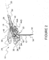
- FIGS. 1-7 there is illustrated one embodiment of a needle safety apparatus 10, constructed in accordance with the principals of the present disclosure.
- the embodiment includes a needle 12 having a distal portion 14 defining a longitudinal axis 16 which is angularly displaced relative to a transverse axis 20 defined by a proximal portion 18 of needle 12.
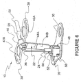
- a shield assembly 22 is mounted with needle 12 and extensible, via an inner bearing 24 and outer bearing 26, between a retracted position ( FIGS. 1 - 2 ) and an extended position ( FIG. 6 ) via intermediate positions ( FIGS. 3 - 5 ).
- This embodiment of a needle safety apparatus 10 is advantageously configured to prevent hazardous exposure to a needle 12 by providing an adequate and reliable safety shield apparatus for port access needle devices as will be discussed below.
- needle safety apparatus 10 includes a hub 28 mounted with the proximal portion 18 of needle 12 and a planar contact surface 30 mounted with outer bearing 26. It is envisioned that planar contact surface 30 may be hingedly or fixedly attached to outer bearing 26.
- the needle safety apparatus 10 according to the present embodiment includes a shield assembly 22 which is extensible between a retracted position and an extended position via fixed positioning of planar contact surface 30 relative to movement of needle 12 along longitudinal axis 16.
- a shield assembly 22 which is extensible between a retracted position and an extended position via fixed positioning of planar contact surface 30 relative to movement of needle 12 along longitudinal axis 16.
- Needle safety apparatus 10 is contemplated for use in the field of medical fluid infusion and/or collection.
- needle safety apparatus 10 is envisioned to be a disposable port access needle device employing, among other things, safety features having shielding capabilities to prevent inadvertent sticking or punctures of clinicians and subjects, as well as uniform and dependable movement of shield assembly 22 during a procedure and a locking mechanism for reliable use.
- the above advantages, among others, realized from the present disclosure are attained through the disclosed needle safety apparatus 10, which is extensible to a protective configuration, as discussed hereinbelow. These features of the present disclosure advantageously facilitate a safe infusion and/or collection of fluids and prevent inadvertent needle stick of a clinician and subject..
- needle safety apparatus 10 may be fabricated from a material suitable for medical applications, such as, for example, polymerics or metals, such as stainless steel, depending on the particular medical application and/or preference of a clinician. Semi-rigid and rigid polymerics are contemplated for fabrication, as well as resilient materials, such as molded medical grade polypropylene. However, one skilled in the art will realize that other materials and fabrication methods suitable for assembly and manufacture, in accordance with the present disclosure, also would be appropriate. Needle safety apparatus 10 may be integrally assembled of its constituent parts. Alternatively, portions of safety shield apparatus 10 can be monolithically formed and assembled therewith.
- needle safety apparatus 10 is employed with an angled needle 12, such as a Huber type safety needle and includes a needle 12, a needle hub 28, a shield assembly 22 and a section of medical tubing 50.
- the needle 12 is formed from an angled cannula. Generally, for the purposes of providing access to medical needle 12 along a plane orthogonal to a line of percutaneous entry and parallel to a plane of an entry site, medical needle 12 is angled. This configuration is consistent with a Huber type safety needle. Other angled medical needles may be protected by the apparatus in accordance with the present disclosure.
- the distal portion 14 of medical needle 12 has an inferiorly disposed sharpened end 32.
- the proximal portion 18 includes a superiorly disposed abrupt end 34 and a medially disposed bend 36 is formed therebetween.
- Needle hub 28 includes a winged portion 38 by which needle hub 28 is grasped and displaced. Needle hub 28 includes an open proximal end configured to accept a tubing segment, and a proximal end configured to accept and securely retain the proximal end of needle which is disposed in the end of said tubing in the interior cavity of the needle hub 28
- Winged portion 38 includes a digital (manipulable) interface which may be facilely gripped by a clinicians fingers.
- Winged portion 38 may include two winged parts 42A, 42B.
- Winged parts 42A, 42B may be hinged or flexible and horizontally disposed, as shown in FIGS. 1 - 5 to provide a low silhouette until needle safety apparatus 10 is to be removed from an insertion site. This configuration advantageously permits less obstruction for tape down and other site preparation over extended periods of use.
- Winged parts 42A, 42B may be articulated to a more vertical orientation (not shown) when extracting medical needle 12.
- Winged portion 38 permits extraction forces to be applied directly above and in-line with a longitudinal axis insertion line of medical needle 12.
- winged parts 42A, 42B may include corrugation, texturing or other process to increase surface friction.
- needle safety apparatus 10 parts may be accomplished by injection molding of needle hub 38 and shield assembly 22, both of which may be injection molded using synthetic resinous material, such as polypropylene.
- Medical tubing 50 may be selected from medical tubing currently commercially available.
- distal portion 14 of needle 12 can be assembled to shield assembly 22, and the shield assembly snapped over the outside surface of needle hub 28.
- Tubing 50 may be displaced through the proximal opening of needle hub 28 as previously disclosed.
- the proximal end of medical needle 12 is displaced into tubing 50 and securely affixed thereat.
- Needle safety apparatus 10 may be properly sterilized and otherwise prepared for storage, shipment and use. Needle safety apparatus 10 may be properly affixed, via planar contact surface 30, and inserted within a subject (not shown) for a port access medical procedure, such as, for example, one or a plurality of infusion and/or collection of fluid procedures. Upon completion of the medical procedure(s), force may be applied to the proximal surface of planar contact surface 30 while retracting forces are applied to winged parts 42A, 42B. Thus, planar contact surface 30 remains in a fixed position, relative to movement of shield assembly 22 to the extended position.
- Inner bearing 24 and outer bearing 26 slidably support medical needle 12 to facilitate extension of shield assembly 22 during extraction.
- Medical needle 12 is thereby extracted from an insertion site.
- needle hub 28 is displaced away from planar contact surface 30 unfolding hinged portions 44A, 44B.
- Proximal hinged portion 44A is hingedly attached to collar 46 and to hinged portion 44B.
- Collar 46 may be monolithically formed with hub 28.
- any reference to hinge portion 44A connected to hub 28 includes connection to collar 46 or connection directly to hub 28.
- Hinged portion 44B is hingedly attached to inner bearing 24.
- the purpose and function of hinged portions 44A, 44B is to serve as a tether for preventing extension of the shield assembly 22 beyond the distal portion 14 of needle 12.
- the tether may be in the form of a cord, strap or the like (not shown).
- Collar 46 is rigidly retained, for example by snap features, to hub 28.
- Shield assembly 22 is thereby articulated until the sharpened tip of medical needle 12 is displaced into protective shielding of shield assembly 22.
- Inner bearing 24 and outer bearing 26 are unreleasably, respectively engaged by latching arm 48. As shown in FIGS. 4 and 5 , the sharpened tip of medical needle 12 is fully enclosed by shield assembly 22.
- outer bearing 26 is monolithically formed with planar contact surface 30 as a substantially cylindrical structure protruding from the proximal surface of planar contact surface 30.
- Inner bearing 24 is a smaller substantially cylindrical structure disposed within the walls of the outer cylinder 26. Outer bearing 26 thus forms a guide for linear translation of the inner cylinder 24 along longitudinal axis 16, while inner bearing 24 forms a guide for linear translation of needle 12.
- a latching arm 48 is formed in the sidewall of outer bearing 26.
- the latching arm 48 allows inner cylinder 24 to translate telescopically when pulled by extended (unfolded) hinged portions 44A, 44B as hub 28 is displaced away from planar contact surface 30.
- the latching arm 48 prevents inner bearing 48 from retracting telescopically in a distal direction thus retaining the shield assembly 22 in a fully extended configuration.
- latching arm 48 may be formed in the sidewall of inner bearing 24.
- a flange 23 on outer bearing 26 interacts with flange 25 on inner bearing 24 as shield assembly 22 is distally extended to retain outer bearing 26 with the shield assembly 22 in a fully extended configuration.
- a wedging portion 52 secures the distal portion 14 of needle 12 within inner bearing 24.
- Wedging portion 52 is pivotally mounted to inner bearing 24 ( FIGS. 2 , 4 and 5 ) or pivotally formed with the inner bearing, for example, by forming a living hinge 58.
- wedging portion 52 is disposed through a cutout 56 in the sidewall of outer bearing 26. Pivoting of wedging portion 52 occurs when inner bearing 24 is extended telescopically in the proximal direction relative to outer bearing 26.
- Cam surface 54 of wedging portion 52 engages the proximal edge of cutout 56 thus pivotally displacing wedging portion 52 within the inner space of inner bearing 24. It is also contemplated that cutout 56 may also comprise an enclosed space.
- wedging portion 52 may embody various shapes to accomplish the function of securing the distal portion 14 of needle 12 within inner bearing 24.
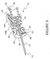
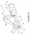
- needle safety apparatus for use, for example, with a straight needle 12 and luer fitting 60 for use with a medical syringe.
- needle hub 28 is be configured to include a luer fitting 60 for attachment to various needle devices such as a syringe or IV set (not shown).
- Needle hub 28 is firmly and securely affixed to the needle 12.
- Collar 46 is adapted for press fit or snapping engagement over needle hub 28.
- Planar contact surface 30 is formed as a flange at the distal edge of outer bearing 26. Operation of the needle safety device with a straight needle is substantially identical to operation with an angled needle apparatus as described hereinbefore.
- Inner bearing 24 and outer bearing 26 slidably support medical needle 12 to facilitate extension of shield assembly 22 during extraction.
- Medical needle 12 is thereby extracted from an insertion site.
- needle hub 28 is displaced away from planar contact surface 30 unfolding hinged portions 44A, 44B.
- Proximal hinged portion 44A is hingedly attached to collar 46 and to hinged portion 44B.
- Hinged portion 44B is hingedly attached to inner bearing 24.
- Collar 46 is rigidly retained, for example, by snap features to hub 28.
- Shield assembly 22 is thereby articulated until the sharpened tip of medical needle 12 is displaced into protective shielding of shield assembly 22.
- Inner bearing 24 and outer bearing 26 are unreleasably engaged by latching arm 48, respectively. As shown in FIGS. 12 - 15 , the sharpened tip of medical needle 12 is fully enclosed by shield assembly 22.
- a latching arm 48 ( FIG. 15 ) is formed in the sidewall of outer bearing 26.
- the latching arm 48 allows inner cylinder 24 to translate telescopically when pulled by extended (unfolded) hinged portions 44A, 44B as hub 28 is displaced away from planar contact surface 30.
- extended (unfolded) hinged portions 44A, 44B as hub 28 is displaced away from planar contact surface 30.
- the latching arm 48 prevents inner bearing 48 from retracting telescopically in distal direction thus retaining the shield assembly 22 in a fully extended configuration.
- a wedging portion 52 secures the distal end 14 of needle 12 within inner bearing 24.
- Wedging portion 52 is pivotally mounted to inner bearing 24 or pivotally formed with the inner bearing, for example, by forming a living hinge 58.
- wedging portion 52 is disposed through a cutout 56 in the sidewall of outer bearing 26. It is also contemplated that the cutout 56 may be an enclosed area providing clearance for wedging portion 52.
- the pivoting of wedging portion 52 occurs when inner bearing 24 is extended telescopically in the proximal direction relative to outer bearing 26.
- Cam surface 54 of wedging portion 52 engages the proximal edge of cutout 56 thus pivotally displacing wedging portion 52 to secure the distal portion 14 of needle 12 within the inner space of inner bearing 24.
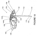
- FIGS. 16-28 there is illustrated another embodiment of a needle safety apparatus 110, constructed in accordance with the principals of the present disclosure.
- the embodiment includes a needle 112 having a distal portion 114 defining a longitudinal axis 116 which is angularly displaced relative to a transverse axis 120 defined by a proximal portion 118 of needle 112.
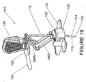
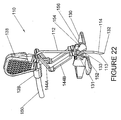
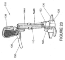
- a shield assembly 122 is mounted with needle 112 and extensible, via an inner bearing 124 and outer bearing 126, between a retracted position ( FIGS. 16 - 18 ) and an extended position ( FIGS. 23 - 26 ) via intermediate positions ( FIGS. 19 - 22 ).
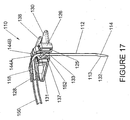
- needle safety apparatus 110 includes a hub 128 mounted with the proximal portion 118 of needle 112 and a planar contact surface 130 mounted with outer bearing 126. It is envisioned that planar contact surface 130 may be hingedly or fixedly attached to outer bearing 126.
- the needle safety apparatus 110 according to the present embodiment includes a shield assembly 122 which is extensible between a retracted position and an extended position via fixed positioning of planar contact surface 130 relative to movement of needle 112 along longitudinal axis 116.
- needle safety apparatus 110 may be fabricated from a material suitable for medical applications, such as, for example, polymerics or metals, such as stainless steel, depending on the particular medical application and/or preference of a clinician. Semi-rigid and rigid polymerics are contemplated for fabrication, as well as resilient materials, such as molded medical grade polypropylene. However, one skilled in the art will realize that other materials and fabrication methods suitable for assembly and manufacture, in accordance with the present disclosure, also would be appropriate. Needle safety apparatus 110 may be integrally assembled of its constituent parts. Alternatively, portions of safety shield apparatus 110 can be monolithically formed and assembled therewith.
- Needle safety apparatus 110 is employed with an angled needle 112, such as a Huber type safety needle and includes a needle 112, a needle hub 128, a shield assembly 122 and a section of medical tubing 150.
- a Huber type safety needle such as a Huber type safety needle and includes a needle 112, a needle hub 128, a shield assembly 122 and a section of medical tubing 150.
- the needle 112 is formed from an angled cannula. Generally, for the purposes of providing access to medical needle 112 along a plane orthogonal to a line of percutaneous entry and parallel to a plane of an entry site, medical needle 112 is angled. This configuration is consistent with a Huber type safety needle. Other angled medical needles may be protected by the apparatus in accordance with the present disclosure.
- the distal portion 114 of medical needle 112 has an inferiorly disposed sharpened end 132.
- the proximal portion 118 includes a superiorly disposed abrupt end 134 and a medially disposed bend 36 is formed therebetween.
- Needle hub 128 includes a winged portion 138 by which needle hub 128 is grasped and displaced. Needle hub 128 includes an open proximal end configured to accept a tubing segment, and a proximal end configured to accept and securely retain the proximal end of needle which is disposed in the end of said tubing in the interior cavity of the needle hub 28
- Winged portion 138 includes a digital (manipulable) interface which may be facilely gripped by a clinicians fingers.
- Winged portion 138 may include two winged parts 142A, 142B.
- Winged parts 142A, 142B may be hinged or flexible and horizontally disposed, as shown in FIGS. 16 - 18 to provide a low silhouette until needle safety apparatus 110 is to be removed from an insertion site This configuration advantageously permits less obstruction for tape down and other site preparation over extended periods of use.
- Winged parts 142A, 142B may be articulated to a more vertical orientation ( FIGS. 20 , 22 , and 23 ) when extracting medical needle 112.
- Winged portion 138 permits extraction forces to be applied directly above and in-line with a longitudinal axis insertion line of medical needle 112.
- winged parts 142A, 142B may include corrugation, texturing or other process to increase surface friction.
- needle safety apparatus 110 parts may be accomplished by injection molding of needle hub 138 and shield assembly 122, both of which may be injection molded using synthetic resinous material, such as polypropylene.
- Medical tubing 150 may be selected from medical tubing currently commercially available.
- distal portion 114 of needle 112 can be assembled to shield assembly 122, and the shield assembly snapped over the outside surface of needle hub 128.
- Tubing 150 may be displaced through the proximal opening of needle hub 128 as previously disclosed. The proximal end of medical needle 112 is displaced into tubing 150 and securely affixed thereat.
- Needle safety apparatus 110 may be properly sterilized and otherwise prepared for storage, shipment and use. Needle safety apparatus 110 may be properly affixed, via planar contact surface 130, and inserted within a subject (not shown) for a port access medical procedure, such as, for example, one or a plurality of infusion and/or collection of fluid procedures. Upon completion of the medical procedure(s), force may be applied to the proximal surface of planar contact surface 130 while retracting forces are applied to winged parts 142A, 142B. Thus, planar contact surface 130 remains in a fixed position, relative to movement of shield assembly 122 to the extended position.
- Inner bearing 124 and outer bearing 126 slidably support medical needle 112 to facilitate extension of shield assembly 122 during extraction. Medical needle 112 is thereby extracted from an insertion site As medical needle 112 is extracted, needle hub 128 is displaced away from planar contact surface 130 unfolding hinged portions 144A, 144B. Proximal hinged portion 144A is hingedly attached to collar 146 and to hinged portion 144B. Collar 146 may be monolithically formed with hub 128. Hence, any reference to hinge portion 144A connected to hub 128 includes connection to collar 146 or connection directly to hub 128. Hinged portion 144B is hingedly attached to inner bearing 124.
- hinged portions 144A, 144B The purpose and function of hinged portions 144A, 144B is to serve as a tether for preventing extension of the shield assembly 122 beyond the distal portion 114 of needle 112. It is envisioned that the tether may be in the form of a cord, strap or the like (not shown). Collar 146 is rigidly retained, for example by snap features, to hub 128. Shield assembly 122 is thereby articulated until the sharpened tip of medical needle 112 is displaced into protective shielding of shield assembly 122. Inner bearing 124 and outer bearing 126 are unreleasably, respectively engaged by one or more latching arms 148. As shown in FIGS.19 and 20 , the sharpened tip of medical needle 112 is fully enclosed by shield assembly 122.
- outer bearing 126 is monolithically formed with planar contact surface 130 as a substantially cylindrical structure protruding from the proximal surface of planar contact surface 130.
- Inner bearing 124 is a smaller substantially cylindrical structure disposed within the walls of the outer cylinder 126. Outer bearing 126 thus forms a guide for linear translation of the inner bearing 124 along longitudinal axis 116, while inner bearing 124 forms a guide for linear translation of needle 112.
- One or more latching arms 148 are formed in the sidewall of inner bearing 124.
- the one or more latching arms 148 allow inner bearing 124 to translate telescopically when pulled by extended (unfolded) hinged portions 144A, 144B as hub 128 is displaced away from planar contact surface 130.
- the sharpened tip of needle 112 is retracted safely within shield assembly 122.
- the one or more latching arms 148 extend onto a corresponding latching surface 129 disposed on the outer bearing 126 to latch the inner bearing 124 in a proximal position when the inner 124 bearing is moved proximally along the longitudinal axis beyond the one or more latching arms 148.
- the one or more latching arms 148 prevent inner bearing 124 from retracting telescopically in a distal direction thus retaining the shield assembly 122 in a fully extended configuration. It is also contemplated that the one or more latching arms 148 may be formed in the sidewall of outer bearing 126 or on wedging portion 152. Flanges 123 and 135 on outer bearing 126 interact with flanges 125 and 137, respectively, on inner bearing 124 as shield assembly 122 is distally extended to retain outer bearing 126 with the shield assembly 122 in a fully extended configuration.
- a wedging portion 152 secures the distal portion 114 of needle 112 within inner bearing 124.
- Wedging portion 152 is pivotally mounted to inner bearing 124 ( FIGS. 17 , 18 , 20 , and 21 ) or pivotally formed with the inner bearing 124. Pivoting of wedging portion 152 occurs when inner bearing 124 is extended telescopically in the proximal direction relative to outer bearing 126.
- Cam surface 154 of wedging portion 152 engages the cam surface 156 of wedging portion 152 thus pivotally displacing wedging portion 152 within the inner space of inner bearing 124.
- wedging portion 152 may embody various shapes to accomplish the function of securing the distal portion 114 of needle 112 within inner bearing 124. Binding of needle 112 occurs as binding surfaces 131 and 133 on wedging portion 152 interact with needle surfaces 113 and 114, respectively.
Abstract
Description
- The present disclosure generally relates to safety shields for medical needles, and more particularly, to safety shields that are extensible to prevent hazardous exposure to a medical needle.
- Cross-contamination and infection from potentially fatal diseases transmitted by inadvertent needle sticks have resulted in the development of a wide variety of safety medical needle devices used in the areas of I.V. therapy, phlebotomy, syringes and specialty medical needle devices. These diseases include the HIV virus, several strains of hepatitis and other blood and body fluid borne diseases.
- Vascular access ports can be surgically implanted to facilitate removal of bodily fluids, such as, for example; blood for testing. Access ports also provide a temporary site for repeated fluid removal, infusion of intravenous fluids or medication infusion. An access port is typically positioned in a body surface of a patient, such as, for example, the chest or arm, to facilitate disposition of a catheter into a blood vessel.
- Typically, port access medical needles, such as a Huber needle, are used with the access ports which are implanted for direct vascular communication. Many Huber needles include an angled cannula shaft having a sharpened tip portion oriented at approximately 90 degrees relative to an attachment portion that connects to a fluid source and/or a fluid receptacle. The angular bend in the cannula shaft allows the attachment portion to be secured to the patient while the access port is employed.
- Access ports typically include a septum positioned under the surface of the patient's skin, which is adapted to receive a Huber needle puncture at a percutaneous insertion site. The septum is conventionally fabricated from a thick elastomeric membrane which facilitates needle penetration and covers an inner chamber for the infusion of medication or removal of bodily fluids.
- Huber needles may be particularly difficult to remove from a needle access port which can result in hazardous exposure of the needle to a patient and a clinician. This is due, at least in part, to the fact that access port septums exhibit forces associated with needle entry and removal, which are much greater than forces normally associated with other medical needle insertion and removal (e.g., with syringes or phlebotomy needles). "Rebound" injuries are typically encountered with Huber needles because of the force required to overcome resistance of the septum of the access port.
- Attempts at overcoming the above retention and resistive forces may result in a reflexive motion (e.g., a jerk) by the clinician removing the needle at the time of extraction, which can contribute to the "rebound" injuries. The reflexive motion may be poorly controlled, oscillatory and, therefore, result in an inadvertent needle stick to the patient and clinician, for example, to a hand which is stabilizing an implanted port. Further, difficulty in removal can force a clinician to make a perpendicular pull, which is transverse to a plane orthogonal to the direction of needle insertion. This can result in injury to the patient and the clinician.
- A number of Huber needle safety devices are known. For example, one particular device involves a shield separate from the needle for shielding the needle. These types of devices disadvantageously require manipulation and operation of separate devices for shielding the needle. These devices are also bulky and cumbersome which can affect accuracy of placement during use.
- Another known attempt at reducing hazards associated with angled needles is a safety device that includes a collapsible pair of wings engaged by the fingers of a clinician to shield the needle. A drawback of devices of this type is that a narrow surface area presses against a patient's skin during withdrawal, which can cause significant pain and discomfort.
-
US 2003/060774 describes a hypodermic needle assembly in which movement of a needle shield into position to block the needle tip occurs when a longitudinal force is applied by insertion of a syringe plunger. The hypodermic needle assembly comprises a needle, a needle hub, and a safety spring clip assembly configured to automatically launch from the needle hub and slide along the needle until the spring clip meets a needle stop at the needle tip to prevent a guard from being removed from the needle shaft. -
US 2003/114797 describes an instrument in which a needle is drawn into a protective cap and sheath arrangement after use for disposal. The cap is tethered to a housing in which the needle is mounted by the sheath. The sheath is made of a film material that has a high tensile strength and a low percent of elongation. The sheath is initially mounted about the needle in a collapsed accordion-like condition between the cap and housing. When the cap is moved along the needle, the sheath is played out over the needle. The cap houses a spring clip to snap over the bore through which the needle is retracted to prevent re-emergence of the needle. The flexible nature of the sheath allows the sheath to pass about the two legs of a Huber needle -
US 2003/100868 describes a medical needle shield apparatus including a shield that is extensible from a retracted position to an extended position to enclose a distal end of a needle. A binding member disposed within the shield defines binding surfaces that form an aperture configured for slidable receipt of the needle between the retracted position and the extended position. The binding member includes a drag-inducing member extending from it that is configured for slidable engagement with the needle between the retracted position and the extended position such that the drag-inducing member engages the needle to create a drag force with the needle. The drag force causes rotation of the binding member relative to a longitudinal axis of the needle such that the binding surfaces engage the needle to prevent slidable movement of the needle in the extended position of, the shield. The binding member also includes a retainer extending from it so that the retainer is engageable with the needle to prevent rotation of the binding member. - The prior art devices may not adequately and reliably shield port access needles to prevent hazardous exposure. A continuing need exists to overcome the disadvantages and drawbacks of the prior art and provide a more adequate and reliable safety apparatus for angled needle devices which sheaths a needle upon removal from an insertion site. Such a safety apparatus may be actuated without applying substantial transverse forces to the needle during removal.
- Therefore, it would be desirable to have a safety apparatus for port access needle devices that sheaths a needle upon removal from an insertion site. It would be highly desirable if the safety apparatus was actuated without applying substantial transverse forces to the needle during removal.
- An aspect of the invention provides a medical needle shield apparatus comprising: a shield being extensible from a retracted position to an extended position to enclose a distal end of a needle, said needle including a proximal end mounted to a hub and said y shield comprising: an outer bearing having a sidewall defining a first interior space about a longitudinal axis; an inner bearing having a sidewall defining a second interior space about said longitudinal axis, wherein said needle is disposed in said second interior space and is movable along said longitudinal axis, said inner bearing disposed in said first interior space and moveable telescopically therein along said longitudinal axis and wherein the inner bearing and the outer bearing remain coaxial throughout movement of the inner bearing relative to the outer bearing; a wedging portion pivotably mounted to said inner bearing and movable with said inner bearing for pivoting and wedging against said needle to secure the distal end of said needle within the second interior space in the extended position; a tether having a proximal end connected to said hub and a distal end connected to said inner bearing for preventing separation of the shield from the needle in the extended position, wherein the tether comprises extendable segments; and a latch which can engage the inner bearing to maintain a latched structure of the inner bearing, outer bearing, extendable segments, needle and hub in a protective configuration about a tip of the needle when retracted into the inner bearing, wherein said shield is extensible along said longitudinal axis from said retracted position to said extended position.
- Objects and advantages of the present disclosure are set forth in part herein and in part will be obvious therefrom, or may be learned by practice of the present disclosure, which is realized and attained by means of the instrumentalities and combinations pointed out in the appended claims.
- The safety apparatus can provide shielding of a sharpened tip of a port access medical needle, such as, for example, a Huber type safety needle, having a sharpened tip at one end and be firmly affixed within a needle hub at the other end during withdrawal from an insertion site Extraction of the needle from the insertion site may require forces significantly greater than forces associated with extracting other medical needles, such as hypodermic syringes or phlebotomy. Thus, the safety apparatus can include a shield assembly having a finger pad for application of restraining forces about the insertion site. The finger pad spreads digitally applied forces to stabilize the implanted portion of the needle.
- The shield assembly contains an inner bearing through which the needle travels during needle extraction. The inner bearing is affixed to the hub via a tether for articulation along the needle during needle extraction. The sharpened tip of the needle is retracted into the inner bearing forming a latched structure of the inner bearing, outer bearing, extendable segments, needle, and hub. The wedging portion can secure or occlude the needle tip within the inner bearing. A latch can engage the inner bearing to maintain the rigid structure in a protective configuration about the sharpened tip. Thus, the needle is extracted and shielded without applying substantial transverse forces to the needle.
- The wedging portion can include a cam surface, which engages the outer bearing sidewall to pivot the wedging portion when the inner portion is moved along the longitudinal axis.
- In an illustrative embodiment of the needle safety apparatus, the inner bearing can move telescopically in the first interior space in response to proximal movement of the hub and extension of the extendable linkage segments.
- In one embodiment, the outer bearing includes a latching arm extending into the first interior space to latch the inner bearing in a proximal position when the inner bearing is moved proximally along the longitudinal axis beyond the latching arm. The wedging portion is thereby retained in a pivoted position closing the second interior space.
- The inner bearing can include a latching arm extending into said second interior space to latch said outer bearing in a proximal position when said outer bearing is moved proximally along said longitudinal axis beyond said latching arm and wherein said wedging portion is thereby retained in a pivoted position.
- The inner bearing can include one or more latching arms extending onto a corresponding latching surface disposed on said outer bearing to latch the inner bearing in a proximal position when the inner bearing is moved proximally along the longitudinal axis beyond said one or more latching arms and wherein said wedging portion is thereby retained in a pivoted position.
- The wedging portion can include one or more latching arms extending onto a corresponding latching surface disposed on said outer bearing to latch the inner bearing in a proximal position when the inner bearing is moved proximally along the longitudinal axis beyond said one or more latching arms and wherein said wedging portion is thereby retained in a pivoted position.
- The outer bearing can include a latching arm extending into a corresponding latching surface of said inner bearing to latch said outer bearing in a proximal position when said outer bearing is moved proximally along said longitudinal axis beyond said latching arm and wherein said wedging portion is thereby retained in a pivoted position.
- The outer bearing can include a distal end having a planar surface substantially orthogonal to said longitudinal axis.
- The planar surface can be hingedly attached to said outer bearing.
- The hub can include a winged portion extending therefrom, said winged portion providing a surface area for gripping.
- An aspect of the invention provides a medical needle shield apparatus comprising: a shield being extensible from a retracted position to an extended position to enclose a distal end of a needle, said needle including a proximal end mounted to a hub and said shield comprising: an outer bearing having a sidewall defining a first interior space about a longitudinal axis; an inner bearing having a sidewall defining a second interior space about said longitudinal axis, wherein said needle is disposed in said second interior space and is movable along said longitudinal axis; said inner bearing disposed in said first interior space and moveable therein along said longitudinal axis; a wedging portion movable with said inner bearing for wedging against said needle to secure the distal end of said needle within the second interior space in the extended position; and a tether having a proximal end connected to said hub and a distal end connected to said inner bearing for preventing separation of the shield from the needle in the extended position.
- Said wedging portion can be pivotably mounted to said inner bearing.
- Said wedging portion can include a cam surface which engages a sidewall of said outer bearing to pivot said wedging portion when said inner portion is moved along said longitudinal axis.
- Said wedging portion can be pivotably mounted to said interior bearing and can include a cam surface which engages said outer bearing sidewall to pivot said wedging portion to an occluding position when said inner bearing is moved along said longitudinal axis.
- Said outer bearing sidewall can include a cutout extending at least partially therethrough, said cutout providing clearance for said wedging portion when said wedging portion is pivoted away from said second interior space.
- Said cutout can include a distal surface which engages said cam surface to pivot said wedging portion.
- Said outer bearing sidewall can include an enclosed space extending from the sidewall, said enclosed space providing clearance for said wedging portion when said wedging portion is pivoted away from said second interior space.
- Said wedging portion can include a plurality of binding surfaces.
- Said wedging portion can include a cam surface which engages a cam surface of said outer bearing to pivot said wedging portion when said inner portion is moved along said longitudinal axis.
- Said wedging portion can be pivotably mounted to said interior bearing and can include a cam surface which engages a cam surface disposed on said outer bearing sidewall to pivot said wedging portion to a secured position when said inner bearing is moved along said longitudinal axis.
- Said tether can comprise extendable linkage segments.
- Said tether can comprise a cord.
- Said inner bearing can move telescopically in said first interior space in response to proximal movement of said hub and extension of said extendable linkage segments.
- Said outer bearing can include a latching arm extending into said first interior space to latch said inner bearing in a proximal position when said inner bearing is moved proximally along said longitudinal axis beyond said latching arm and wherein said wedging portion is thereby retained in a pivoted position.
- Said inner bearing can include a latching arm extending into said second interior space to latch said outer bearing in a proximal position when said outer bearing is moved proximally along said longitudinal axis beyond said latching arm and wherein said wedging portion is thereby retained in a pivoted position.
- Said inner bearing can include one or more latching arms extending onto a corresponding latching surface disposed on said outer bearing to latch the inner bearing in a proximal position when the inner bearing is moved proximally along the longitudinal axis beyond said one or more latching arms and wherein said wedging portion is thereby retained in a pivoted position.
- Said wedging portion can include one or more latching arms extending onto a corresponding latching surface disposed on said outer bearing to latch the inner bearing in a proximal position when the inner bearing is moved proximally along the longitudinal axis beyond said one or more latching arms and wherein said wedging portion is thereby retained in a pivoted position.
- Said outer bearing can include a latching arm extending into a corresponding latching surface of said inner bearing to latch said outer bearing in a proximal position when said outer bearing is moved proximally along said longitudinal axis beyond said latching arm and wherein said wedging portion is thereby retained in a pivoted position.
- Said outer bearing can include a distal end having a planar surface substantially orthogonal to said longitudinal axis.
- Said planar surface can be hingedly attached to said outer bearing.
- Said needle can include a bend of about 90 degrees between said proximal and distal ends.
- Said hub can include a winged portion extending therefrom, said winged portion providing a surface area for gripping.
- The objects and features of the present disclosure, which are believed to be novel, are set forth with particularity in the appended claims. The present disclosure, both as to its organization and manner of operation, together with further objectives and advantages, may be best understood by reference to the following description, taken in connection with the accompanying drawings, wherein:
-
FIGURE 1 is a perspective view of a needle safety apparatus adapted for use with a Huber needle in a fully unshielded configuration according to an illustrative embodiment of the present disclosure; -
FIGURE 2 is a cross sectional perspective view of a needle safety apparatus adapted for use with a Huber needle in a fully unshielded configuration according to an illustrative embodiment of the present disclosure; -
FIGURE 3 is a perspective view of a needle safety apparatus adapted for use with a Huber needle in a partially retracted configuration according to an illustrative embodiment of the present disclosure; -
FIGURE 4 is a cross sectional perspective view of a needle safety apparatus adapted for use with a Huber needle in a partially retracted configuration according an illustrative embodiment of the present disclosure; -
FIGURE 5 is a cross sectional perspective view of a needle safety apparatus adapted for use with a Huber needle in a retracted unlatched configuration according to an illustrative embodiment of the present disclosure; -
FIGURE 6 is a perspective view of a needle safety apparatus adapted for use with a Huber needle in a shielded and latched configuration according to an illustrative embodiment of the present disclosure; -
FIGURE 7 is a cross sectional perspective view of a needle safety apparatus adapted for use with a Huber needle in a shielded and latched configuration according to an illustrative embodiment of the present disclosure; -
FIGURE 8 is a perspective view of a needle safety apparatus adapted for use with a syringe needle in a fully unshielded configuration according to an illustrative embodiment of the present disclosure; -
FIGURE 9 is a cross sectional perspective view of a needle safety apparatus adapted for use with a syringe needle in a fully unshielded configuration according to an illustrative embodiment of the present disclosure; -
FIGURE 10 is a perspective view of a needle safety apparatus adapted for use with a syringe needle in a partially retracted configuration according to an illustrative embodiment of the present disclosure; -
FIGURE 11 is a cross sectional perspective view of a needle safety apparatus adapted for use with a syringe needle in a partially retracted configuration according to an illustrative embodiment of the present disclosure; -
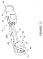
FIGURE 12 is a perspective view of a needle safety apparatus adapted for use with a syringe needle in a retracted unlatched configuration according to an illustrative embodiment of the present disclosure; -
FIGURE 13 is a cross sectional perspective view of a needle safety apparatus adapted for use with a syringe needle in a retracted unlatched configuration according to an illustrative embodiment of the present disclosure; -
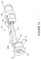
FIGURE 14 is a perspective view of a needle safety apparatus adapted for use with a syringe needle in a shielded and latched configuration according to an illustrative embodiment of the present disclosure; -
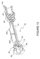
FIGURE 15 is a cross sectional perspective view of a needle safety apparatus adapted for use with a syringe needle in a shielded and latched configuration according to an illustrative embodiment of the present disclosure; -
FIGURE 16 is a perspective view of a needle safety apparatus adapted for use with a Huber needle in a fully retracted and unshielded configuration according to an illustrative embodiment of the present disclosure; -
FIGURE 17 is a cross sectional perspective view of a needle safety apparatus adapted for use with a Huber needle in a fully retracted and unshielded configuration according to an illustrative embodiment of the present disclosure; -
FIGURE 18 is an additional cross sectional perspective view of a needle safety apparatus adapted for use with a Huber needle in a fully retracted and unshielded configuration according to an illustrative embodiment of the present disclosure; -
FIGURE 19 is a perspective view of a needle safety apparatus adapted for use with a Huber needle in a partially retracted configuration according to an illustrative embodiment of the present disclosure; -
FIGURE 20 is a cross sectional perspective view of a needle safety apparatus adapted for use with a Huber needle in a partially retracted unlatched configuration according to an illustrative embodiment of the present disclosure; -
FIGURE 21 is a detail cross sectional perspective view of a needle safety apparatus adapted for use with a Huber needle in a partially retracted unlatched configuration according to an illustrative embodiment of the present disclosure; -
FIGURE 22 is a cross sectional perspective view of a needle safety apparatus adapted for use with a Huber needle in a partially retracted unlatched configuration according to an illustrative embodiment of the present disclosure; -
FIGURE 23 is a perspective view of a needle safety apparatus adapted for use with a Huber needle in a shielded and latched configuration according to an illustrative embodiment of the present disclosure; -
FIGURE 24 is a cross sectional perspective view of a needle safety apparatus adapted for use with a Huber needle in a shielded and latched configuration according to an illustrative embodiment of the present disclosure; -
FIGURE 25 is a detail cross sectional perspective view of a needle safety apparatus adapted for use with a Huber needle in a shielded and latched configuration according to an illustrative embodiment of the present disclosure; -
FIGURE 26 is a cross sectional perspective view of a needle safety apparatus adapted for use with a Huber needle in a shielded and latched configuration according to an illustrative embodiment of the present disclosure; -
FIGURE 27 is a cross sectional perspective view of an inner and outer bearing of a needle safety apparatus adapted for use with a syringe needle according to an illustrative embodiment of the present disclosure; and -
FIGURE 28 is a perspective view of a wedging portion of a needle safety apparatus adapted for use with a syringe needle according to an illustrative embodiment of the present disclosure. - The exemplary embodiments of the needle safety apparatus and methods of operation disclosed are discussed in terms of medical needles for infusion of intravenous fluids, medication infusion or fluid collection, and more particularly in terms of needle apparatus that prevent hazardous exposure to the needle including, for example, inadvertent needle stick. It is contemplated that the needle may be shielded during use including storage, transport, fluid infusion and/or collection, subsequent thereto, etc. It is envisioned that the present disclosure, however, finds application to a wide variety of needles and devices for the infusion of preventive medications, medicaments, therapeutics, etc. to a subject. It is also envisioned that the present disclosure may be employed for collection of body fluids, including, those employed during procedures relating to phlebotomy, digestive, intestinal, urinary, veterinary, etc.
- In the discussion that follows, the term "proximal" refers to a portion of a structure that is closer to a clinician, and the term "distal" refers to a portion that is further from the clinician. As used herein, the term "subject" refers to a patient that receives infusions or has blood and/or fluid collected therefrom using the safety shield apparatus. According to the present disclosure, the term "clinician" refers to an individual administering an infusion, performing fluid collection, installing or removing a needle cannula from a safety shield apparatus and may include support personnel.
- The following discussion includes a description of the needle safety apparatus, followed by a description of the method of operating the needle safety apparatus in accordance with the present disclosure. Reference will now be made in detail to the exemplary embodiments of the disclosure, which are illustrated in the accompanying figures.
- Turning now to the figures wherein like components are designated by like reference numerals throughout the several views. Referring initially to
FIGS. 1-7 , there is illustrated one embodiment of aneedle safety apparatus 10, constructed in accordance with the principals of the present disclosure. The embodiment includes aneedle 12 having adistal portion 14 defining alongitudinal axis 16 which is angularly displaced relative to atransverse axis 20 defined by aproximal portion 18 ofneedle 12. Ashield assembly 22 is mounted withneedle 12 and extensible, via aninner bearing 24 andouter bearing 26, between a retracted position (FIGS. 1 - 2 ) and an extended position (FIG. 6 ) via intermediate positions (FIGS. 3 - 5 ). This embodiment of aneedle safety apparatus 10 is advantageously configured to prevent hazardous exposure to aneedle 12 by providing an adequate and reliable safety shield apparatus for port access needle devices as will be discussed below. - The embodiment of
needle safety apparatus 10 as discussed below includes ahub 28 mounted with theproximal portion 18 ofneedle 12 and aplanar contact surface 30 mounted withouter bearing 26. It is envisioned thatplanar contact surface 30 may be hingedly or fixedly attached toouter bearing 26. Theneedle safety apparatus 10 according to the present embodiment includes ashield assembly 22 which is extensible between a retracted position and an extended position via fixed positioning ofplanar contact surface 30 relative to movement ofneedle 12 alonglongitudinal axis 16. Thus, another advantage of the present disclosure is thatneedle safety apparatus 10 is actuated without applying substantial transverse forces toneedle 12 during removal, thus providing a higher degree of safety to the clinician and subject. Further, this configuration ofneedle safety apparatus 10 advantageously provides an automatic shielding ofneedle 12 asshield assembly 22 ifs manipulated to the extended position as will be discussed. - -
Needle safety apparatus 10 is contemplated for use in the field of medical fluid infusion and/or collection. At least one embodiment ofneedle safety apparatus 10 is envisioned to be a disposable port access needle device employing, among other things, safety features having shielding capabilities to prevent inadvertent sticking or punctures of clinicians and subjects, as well as uniform and dependable movement ofshield assembly 22 during a procedure and a locking mechanism for reliable use. The above advantages, among others, realized from the present disclosure are attained through the disclosedneedle safety apparatus 10, which is extensible to a protective configuration, as discussed hereinbelow. These features of the present disclosure advantageously facilitate a safe infusion and/or collection of fluids and prevent inadvertent needle stick of a clinician and subject.. - The component parts of
needle safety apparatus 10 may be fabricated from a material suitable for medical applications, such as, for example, polymerics or metals, such as stainless steel, depending on the particular medical application and/or preference of a clinician. Semi-rigid and rigid polymerics are contemplated for fabrication, as well as resilient materials, such as molded medical grade polypropylene. However, one skilled in the art will realize that other materials and fabrication methods suitable for assembly and manufacture, in accordance with the present disclosure, also would be appropriate.Needle safety apparatus 10 may be integrally assembled of its constituent parts. Alternatively, portions ofsafety shield apparatus 10 can be monolithically formed and assembled therewith. - Referring to
FIGS. 1 - 7 ,needle safety apparatus 10 is employed with anangled needle 12, such as a Huber type safety needle and includes aneedle 12, aneedle hub 28, ashield assembly 22 and a section ofmedical tubing 50. - In the illustrative embodiment, the
needle 12 is formed from an angled cannula. Generally, for the purposes of providing access tomedical needle 12 along a plane orthogonal to a line of percutaneous entry and parallel to a plane of an entry site,medical needle 12 is angled. This configuration is consistent with a Huber type safety needle. Other angled medical needles may be protected by the apparatus in accordance with the present disclosure. Thedistal portion 14 ofmedical needle 12 has an inferiorly disposed sharpenedend 32. Theproximal portion 18 includes a superiorly disposedabrupt end 34 and a medially disposedbend 36 is formed therebetween. -
Needle hub 28 includes awinged portion 38 by whichneedle hub 28 is grasped and displaced.Needle hub 28 includes an open proximal end configured to accept a tubing segment, and a proximal end configured to accept and securely retain the proximal end of needle which is disposed in the end of said tubing in the interior cavity of theneedle hub 28 -
Winged portion 38 includes a digital (manipulable) interface which may be facilely gripped by a clinicians fingers.Winged portion 38 may include twowinged parts Winged parts FIGS. 1 - 5 to provide a low silhouette untilneedle safety apparatus 10 is to be removed from an insertion site. This configuration advantageously permits less obstruction for tape down and other site preparation over extended periods of use. -
Winged parts medical needle 12.Winged portion 38 permits extraction forces to be applied directly above and in-line with a longitudinal axis insertion line ofmedical needle 12. To aid in gripping and transferring extraction forces towinged portion 38,winged parts - The manufacture of
needle safety apparatus 10 parts may be accomplished by injection molding ofneedle hub 38 andshield assembly 22, both of which may be injection molded using synthetic resinous material, such as polypropylene.Medical tubing 50 may be selected from medical tubing currently commercially available. To assembleneedle safety apparatus 10,distal portion 14 ofneedle 12 can be assembled to shieldassembly 22, and the shield assembly snapped over the outside surface ofneedle hub 28.Tubing 50 may be displaced through the proximal opening ofneedle hub 28 as previously disclosed. The proximal end ofmedical needle 12 is displaced intotubing 50 and securely affixed thereat. -
Needle safety apparatus 10 may be properly sterilized and otherwise prepared for storage, shipment and use.Needle safety apparatus 10 may be properly affixed, viaplanar contact surface 30, and inserted within a subject (not shown) for a port access medical procedure, such as, for example, one or a plurality of infusion and/or collection of fluid procedures. Upon completion of the medical procedure(s), force may be applied to the proximal surface ofplanar contact surface 30 while retracting forces are applied towinged parts planar contact surface 30 remains in a fixed position, relative to movement ofshield assembly 22 to the extended position. -
Inner bearing 24 andouter bearing 26 slidably supportmedical needle 12 to facilitate extension ofshield assembly 22 during extraction.Medical needle 12 is thereby extracted from an insertion site. Asmedical needle 12 is extracted,needle hub 28 is displaced away fromplanar contact surface 30 unfolding hingedportions portion 44A is hingedly attached tocollar 46 and to hingedportion 44B.Collar 46 may be monolithically formed withhub 28. Hence, any reference to hingeportion 44A connected tohub 28 includes connection tocollar 46 or connection directly tohub 28. Hingedportion 44B is hingedly attached toinner bearing 24. The purpose and function of hingedportions shield assembly 22 beyond thedistal portion 14 ofneedle 12. It is envisioned that the tether may be in the form of a cord, strap or the like (not shown).Collar 46 is rigidly retained, for example by snap features, tohub 28.Shield assembly 22 is thereby articulated until the sharpened tip ofmedical needle 12 is displaced into protective shielding ofshield assembly 22.Inner bearing 24 andouter bearing 26 are unreleasably, respectively engaged by latchingarm 48. As shown inFIGS. 4 and5 , the sharpened tip ofmedical needle 12 is fully enclosed byshield assembly 22. - In the illustrative embodiment,
outer bearing 26 is monolithically formed withplanar contact surface 30 as a substantially cylindrical structure protruding from the proximal surface ofplanar contact surface 30.Inner bearing 24 is a smaller substantially cylindrical structure disposed within the walls of theouter cylinder 26.Outer bearing 26 thus forms a guide for linear translation of theinner cylinder 24 alonglongitudinal axis 16, whileinner bearing 24 forms a guide for linear translation ofneedle 12. - A latching
arm 48 is formed in the sidewall ofouter bearing 26. The latchingarm 48 allowsinner cylinder 24 to translate telescopically when pulled by extended (unfolded) hingedportions hub 28 is displaced away fromplanar contact surface 30. Whenshield assembly 22 is fully extended, the sharpened tip ofneedle 12 is retracted safely withinshield assembly 22. The latchingarm 48 preventsinner bearing 48 from retracting telescopically in a distal direction thus retaining theshield assembly 22 in a fully extended configuration. It is also contemplated that latchingarm 48 may be formed in the sidewall ofinner bearing 24. Aflange 23 onouter bearing 26 interacts withflange 25 oninner bearing 24 asshield assembly 22 is distally extended to retainouter bearing 26 with theshield assembly 22 in a fully extended configuration. - In an illustrative embodiment, a wedging
portion 52 secures thedistal portion 14 ofneedle 12 withininner bearing 24. Wedgingportion 52 is pivotally mounted to inner bearing 24 (FIGS. 2 ,4 and5 ) or pivotally formed with the inner bearing, for example, by forming a livinghinge 58. Whenneedle 12 is extended and unshielded, wedgingportion 52 is disposed through acutout 56 in the sidewall ofouter bearing 26. Pivoting of wedgingportion 52 occurs wheninner bearing 24 is extended telescopically in the proximal direction relative toouter bearing 26. Cam surface 54 of wedgingportion 52 engages the proximal edge ofcutout 56 thus pivotally displacing wedgingportion 52 within the inner space ofinner bearing 24. It is also contemplated thatcutout 56 may also comprise an enclosed space. Further, wedgingportion 52 may embody various shapes to accomplish the function of securing thedistal portion 14 ofneedle 12 withininner bearing 24. - Referring now to
FIGS. 8 - 15 , an embodiment of the needle safety apparatus is disclosed for use, for example, with astraight needle 12 and luer fitting 60 for use with a medical syringe. In thisembodiment needle hub 28 is be configured to include a luer fitting 60 for attachment to various needle devices such as a syringe or IV set (not shown). -
Needle hub 28 is firmly and securely affixed to theneedle 12.Collar 46 is adapted for press fit or snapping engagement overneedle hub 28.Planar contact surface 30 is formed as a flange at the distal edge ofouter bearing 26. Operation of the needle safety device with a straight needle is substantially identical to operation with an angled needle apparatus as described hereinbefore. -
Inner bearing 24 andouter bearing 26 slidably supportmedical needle 12 to facilitate extension ofshield assembly 22 during extraction.Medical needle 12 is thereby extracted from an insertion site. Asmedical needle 12 is extracted,needle hub 28 is displaced away fromplanar contact surface 30 unfolding hingedportions portion 44A is hingedly attached tocollar 46 and to hingedportion 44B. Hingedportion 44B is hingedly attached toinner bearing 24.Collar 46 is rigidly retained, for example, by snap features tohub 28.Shield assembly 22 is thereby articulated until the sharpened tip ofmedical needle 12 is displaced into protective shielding ofshield assembly 22.Inner bearing 24 andouter bearing 26 are unreleasably engaged by latchingarm 48, respectively. As shown inFIGS. 12 - 15 , the sharpened tip ofmedical needle 12 is fully enclosed byshield assembly 22. - A latching arm 48 (
FIG. 15 ) is formed in the sidewall ofouter bearing 26. The latchingarm 48 allowsinner cylinder 24 to translate telescopically when pulled by extended (unfolded) hingedportions hub 28 is displaced away fromplanar contact surface 30. Whenshield assembly 22 is fully extended, thedistal portion 14 ofneedle 12 is retracted safely withinshield assembly 22. The latchingarm 48 preventsinner bearing 48 from retracting telescopically in distal direction thus retaining theshield assembly 22 in a fully extended configuration. - In an illustrative embodiment, a wedging
portion 52 secures thedistal end 14 ofneedle 12 withininner bearing 24. Wedgingportion 52 is pivotally mounted toinner bearing 24 or pivotally formed with the inner bearing, for example, by forming a livinghinge 58. Whenneedle 12 is extended and unshielded, wedgingportion 52 is disposed through acutout 56 in the sidewall ofouter bearing 26. It is also contemplated that thecutout 56 may be an enclosed area providing clearance for wedgingportion 52. The pivoting of wedgingportion 52 occurs wheninner bearing 24 is extended telescopically in the proximal direction relative toouter bearing 26. Cam surface 54 of wedgingportion 52 engages the proximal edge ofcutout 56 thus pivotally displacing wedgingportion 52 to secure thedistal portion 14 ofneedle 12 within the inner space ofinner bearing 24. - Referring to
FIGS. 16-28 , there is illustrated another embodiment of aneedle safety apparatus 110, constructed in accordance with the principals of the present disclosure. The embodiment includes aneedle 112 having adistal portion 114 defining alongitudinal axis 116 which is angularly displaced relative to atransverse axis 120 defined by aproximal portion 118 ofneedle 112. Ashield assembly 122 is mounted withneedle 112 and extensible, via aninner bearing 124 andouter bearing 126, between a retracted position (FIGS. 16 - 18 ) and an extended position (FIGS. 23 - 26 ) via intermediate positions (FIGS. 19 - 22 ). - The embodiment of
needle safety apparatus 110 as discussed below includes ahub 128 mounted with theproximal portion 118 ofneedle 112 and aplanar contact surface 130 mounted withouter bearing 126. It is envisioned thatplanar contact surface 130 may be hingedly or fixedly attached toouter bearing 126. Theneedle safety apparatus 110 according to the present embodiment includes ashield assembly 122 which is extensible between a retracted position and an extended position via fixed positioning ofplanar contact surface 130 relative to movement ofneedle 112 alonglongitudinal axis 116. - The component parts of
needle safety apparatus 110 may be fabricated from a material suitable for medical applications, such as, for example, polymerics or metals, such as stainless steel, depending on the particular medical application and/or preference of a clinician. Semi-rigid and rigid polymerics are contemplated for fabrication, as well as resilient materials, such as molded medical grade polypropylene. However, one skilled in the art will realize that other materials and fabrication methods suitable for assembly and manufacture, in accordance with the present disclosure, also would be appropriate.Needle safety apparatus 110 may be integrally assembled of its constituent parts. Alternatively, portions ofsafety shield apparatus 110 can be monolithically formed and assembled therewith. -
Needle safety apparatus 110 is employed with anangled needle 112, such as a Huber type safety needle and includes aneedle 112, aneedle hub 128, ashield assembly 122 and a section ofmedical tubing 150. - In the illustrative embodiment, the
needle 112 is formed from an angled cannula. Generally, for the purposes of providing access tomedical needle 112 along a plane orthogonal to a line of percutaneous entry and parallel to a plane of an entry site,medical needle 112 is angled. This configuration is consistent with a Huber type safety needle. Other angled medical needles may be protected by the apparatus in accordance with the present disclosure. Thedistal portion 114 ofmedical needle 112 has an inferiorly disposed sharpenedend 132. Theproximal portion 118 includes a superiorly disposed abrupt end 134 and a medially disposedbend 36 is formed therebetween. -
Needle hub 128 includes awinged portion 138 by whichneedle hub 128 is grasped and displaced.Needle hub 128 includes an open proximal end configured to accept a tubing segment, and a proximal end configured to accept and securely retain the proximal end of needle which is disposed in the end of said tubing in the interior cavity of theneedle hub 28 -
Winged portion 138 includes a digital (manipulable) interface which may be facilely gripped by a clinicians fingers.Winged portion 138 may include twowinged parts Winged parts FIGS. 16 - 18 to provide a low silhouette untilneedle safety apparatus 110 is to be removed from an insertion site This configuration advantageously permits less obstruction for tape down and other site preparation over extended periods of use. -
Winged parts FIGS. 20 ,22 , and23 ) when extractingmedical needle 112.Winged portion 138 permits extraction forces to be applied directly above and in-line with a longitudinal axis insertion line ofmedical needle 112. To aid in gripping and transferring extraction forces towinged portion 138,winged parts - The manufacture of
needle safety apparatus 110 parts may be accomplished by injection molding ofneedle hub 138 andshield assembly 122, both of which may be injection molded using synthetic resinous material, such as polypropylene.Medical tubing 150 may be selected from medical tubing currently commercially available. To assembleneedle safety apparatus 110,distal portion 114 ofneedle 112 can be assembled to shieldassembly 122, and the shield assembly snapped over the outside surface ofneedle hub 128.Tubing 150 may be displaced through the proximal opening ofneedle hub 128 as previously disclosed. The proximal end ofmedical needle 112 is displaced intotubing 150 and securely affixed thereat. -
Needle safety apparatus 110 may be properly sterilized and otherwise prepared for storage, shipment and use.Needle safety apparatus 110 may be properly affixed, viaplanar contact surface 130, and inserted within a subject (not shown) for a port access medical procedure, such as, for example, one or a plurality of infusion and/or collection of fluid procedures. Upon completion of the medical procedure(s), force may be applied to the proximal surface ofplanar contact surface 130 while retracting forces are applied towinged parts planar contact surface 130 remains in a fixed position, relative to movement ofshield assembly 122 to the extended position. -
Inner bearing 124 andouter bearing 126 slidably supportmedical needle 112 to facilitate extension ofshield assembly 122 during extraction.Medical needle 112 is thereby extracted from an insertion site Asmedical needle 112 is extracted,needle hub 128 is displaced away fromplanar contact surface 130 unfolding hingedportions portion 144A is hingedly attached to collar 146 and to hingedportion 144B. Collar 146 may be monolithically formed withhub 128. Hence, any reference to hingeportion 144A connected tohub 128 includes connection to collar 146 or connection directly tohub 128. Hingedportion 144B is hingedly attached toinner bearing 124. The purpose and function of hingedportions shield assembly 122 beyond thedistal portion 114 ofneedle 112. It is envisioned that the tether may be in the form of a cord, strap or the like (not shown). Collar 146 is rigidly retained, for example by snap features, tohub 128.Shield assembly 122 is thereby articulated until the sharpened tip ofmedical needle 112 is displaced into protective shielding ofshield assembly 122.Inner bearing 124 andouter bearing 126 are unreleasably, respectively engaged by one or more latchingarms 148. As shown inFIGS.19 and20 , the sharpened tip ofmedical needle 112 is fully enclosed byshield assembly 122. - In the illustrative embodiment,
outer bearing 126 is monolithically formed withplanar contact surface 130 as a substantially cylindrical structure protruding from the proximal surface ofplanar contact surface 130.Inner bearing 124 is a smaller substantially cylindrical structure disposed within the walls of theouter cylinder 126.Outer bearing 126 thus forms a guide for linear translation of theinner bearing 124 alonglongitudinal axis 116, whileinner bearing 124 forms a guide for linear translation ofneedle 112. - One or more
latching arms 148 are formed in the sidewall ofinner bearing 124. The one or more latchingarms 148 allowinner bearing 124 to translate telescopically when pulled by extended (unfolded) hingedportions hub 128 is displaced away fromplanar contact surface 130. Whenshield assembly 122 is fully extended, the sharpened tip ofneedle 112 is retracted safely withinshield assembly 122. In the fully extended position, the one or more latchingarms 148 extend onto acorresponding latching surface 129 disposed on theouter bearing 126 to latch theinner bearing 124 in a proximal position when the inner 124 bearing is moved proximally along the longitudinal axis beyond the one or more latchingarms 148. Hence, the one or more latchingarms 148 preventinner bearing 124 from retracting telescopically in a distal direction thus retaining theshield assembly 122 in a fully extended configuration. It is also contemplated that the one or more latchingarms 148 may be formed in the sidewall ofouter bearing 126 or on wedgingportion 152.Flanges outer bearing 126 interact withflanges inner bearing 124 asshield assembly 122 is distally extended to retainouter bearing 126 with theshield assembly 122 in a fully extended configuration. - In an illustrative embodiment, a wedging
portion 152 secures thedistal portion 114 ofneedle 112 withininner bearing 124. Wedgingportion 152 is pivotally mounted to inner bearing 124 (FIGS. 17 ,18 ,20 , and21 ) or pivotally formed with theinner bearing 124. Pivoting of wedgingportion 152 occurs wheninner bearing 124 is extended telescopically in the proximal direction relative toouter bearing 126.Cam surface 154 of wedgingportion 152 engages thecam surface 156 of wedgingportion 152 thus pivotally displacing wedgingportion 152 within the inner space ofinner bearing 124. Further, wedgingportion 152 may embody various shapes to accomplish the function of securing thedistal portion 114 ofneedle 112 withininner bearing 124. Binding ofneedle 112 occurs as bindingsurfaces portion 152 interact withneedle surfaces - It will be understood that various modifications may be made to the embodiments disclosed herein. Therefore, the above description should not be construed as limiting, but merely as exemplification of the various embodiments. Those skilled in the art will envision other modifications within the scope of the claims appended hereto.
Claims (16)
- A medical needle shield apparatus (10, 110) comprising:a shield (22, 122) being extensible from a retracted position to an extended position to enclose a distal end of a needle (12, 112), said needle including a proximal end (18, 118) mounted to a hub (28, 128) and said shield comprising:an outer bearing (26, 126) having a sidewall defining a first interior space about a longitudinal axis (16, 116);an inner bearing (24,124) having a sidewall defining a second interior space about said longitudinal axis, wherein said needle is disposed in said second interior space and is movable along said longitudinal axis, said inner bearing disposed in said first interior space and moveable telescopically therein along said longitudinal axis and wherein the inner bearing and the outer bearing remain coaxial throughout movement of the inner bearing relative to the outer bearing;a wedging portion (52, 152) pivotably mounted to said inner bearing and movable with said inner bearing for pivoting and wedging against said needle to secure the distal end of said needle within the second interior space in the extended position;a tether having a proximal end connected to said hub (28, 128) and a distal end connected to said inner bearing (24, 124) for preventing separation of the shield (22, 122) from the needle in the extended position, wherein the tether comprises extendable segments (44A, 44B); anda latch which can engage the inner bearing (24, 124) to maintain a latched structure of the inner bearing (24, 124), outer bearing (26, 126), extendable segments (44A, 44B), needle (12, 112) and hub (28, 128) in a protective configuration about a tip (32, 132) of the needle when retracted into the inner bearing (24, 124), wherein said shield is extensible along said longitudinal axis from said retracted position to said extended position.
- The medical needle shield apparatus (10, 110) according to claim 1, wherein the inner bearing (24, 124) and outer bearing (26, 126) slidably support the needle (12, 112) to facilitate extension of the shield (22, 122) during extraction of the needle.
- The medical needle shield apparatus (10, 110) according to claim 1, wherein the outer bearing (26, 126) is monolithically formed.
- The medical needle shield apparatus (10) according to claim 3, wherein the outer bearing (26) includes a planar contact surface (30) as a cylindrical structure protruding from a proximal surface of the planar contact surface.
- The medical needle shield apparatus (10, 110) according to claim 1, wherein the outer bearing (26, 126) is a cylindrical structure and the inner bearing (24, 124) is a smaller cylindrical structure disposed within the walls of the outer bearing.
- The medical needle shield apparatus (10, 110) according to claim 5, wherein the outer bearing (26, 126) forms a guide for linear translation of the inner bearing (24, 124) along the longitudinal axis (16, 116), while the inner bearing (24, 124) forms a guide for linear translation of the needle (12, 112).
- The medical needle shield apparatus (10, 110) according to claim 1, wherein said tether comprises linkages or a cord.
- The medical needle shield apparatus (10, 110) according to claim 1, wherein said inner bearing (24, 124) moves telescopically in said first interior space in response to proximal movement of said hub (28, 128) and extension of said tether.
- The medical needle shield apparatus (10) according to claim 1, wherein said outer bearing (26) includes a latching arm (48) of the latch extending into said first interior space to latch said inner bearing in a proximal position when said inner bearing is moved proximally along said longitudinal axis beyond said latching arm and wherein said wedging portion is thereby retained in a pivoted position.
- The medical needle shield apparatus (110) according to claim 1, wherein said inner bearing (124) includes a latching arm (148) of the latch extending into said second interior space to latch said outer bearing in a proximal position when said outer bearing (126) is moved proximally along said longitudinal axis beyond said latching arm and wherein said wedging portion is thereby retained in a pivoted position.
- The medical needle shield apparatus (110) according to claim 1, wherein said inner bearing (124) includes one or more latching arms (148) of the latch extending onto a corresponding latching surface disposed on said outer bearing (126) to latch the inner bearing in a proximal position when the inner bearing is moved proximally along the longitudinal axis beyond said one or more latching arms and wherein said wedging portion is thereby retained in a pivoted position.
- The medical needle shield apparatus (10, 110) according to claim 1, wherein said wedging portion (52, 152) includes one or more latching arms of the latch extending onto a corresponding latching surface disposed on said outer bearing (26, 126) to latch the inner bearing in a proximal position when the inner bearing is moved proximally along the longitudinal axis beyond said one or more latching arms and wherein said wedging portion is thereby retained in a pivoted position.
- The medical needle shield apparatus (10) according to claim 1, wherein said outer bearing (26) includes a latching arm (48) of the latch extending into a corresponding latching surface of said inner bearing (24) to latch said outer bearing in a proximal position when said outer bearing is moved proximally along said longitudinal axis beyond said latching arm and wherein said wedging portion is thereby retained in a pivoted position.
- The medical needle shield apparatus (10, 110) according to claim 1, wherein said outer bearing (26, 126) includes a distal end having a planar surface (30, 130) orthogonal to said longitudinal axis.
- The medical needle shield apparatus (10, 110) according to claim 14, wherein said planar surface (30, 130) is hingedly attached to said outer bearing (26, 126).
- The medical needle shield apparatus (10, 110) according to claim 1, wherein said hub (28, 128) includes a winged portion (38, 138) extending therefrom, said winged portion providing a surface area (42A, 42B, 142A, 142B) for gripping.
Applications Claiming Priority (4)
| Application Number | Priority Date | Filing Date | Title |
|---|---|---|---|
| US10/712,570 US6997902B2 (en) | 2003-11-13 | 2003-11-13 | Safety shield for medical needles |
| US10/919,893 US7351230B2 (en) | 2003-11-13 | 2004-08-17 | Safety shield for medical needles |
| EP10159601.3A EP2206528B1 (en) | 2003-11-13 | 2004-11-12 | Safety shield for medical needle devices |
| EP04819105A EP1682202B1 (en) | 2003-11-13 | 2004-11-12 | Safety shield for medical needles |
Related Parent Applications (5)
| Application Number | Title | Priority Date | Filing Date |
|---|---|---|---|
| EP04819105.0 Division | 2004-11-12 | ||
| EP04819105A Division EP1682202B1 (en) | 2003-11-13 | 2004-11-12 | Safety shield for medical needles |
| EP10159601.3A Division EP2206528B1 (en) | 2003-11-13 | 2004-11-12 | Safety shield for medical needle devices |
| EP10159601.3A Division-Into EP2206528B1 (en) | 2003-11-13 | 2004-11-12 | Safety shield for medical needle devices |
| EP10159601.3 Division | 2010-04-12 |
Publications (3)
| Publication Number | Publication Date |
|---|---|
| EP2332594A2 EP2332594A2 (en) | 2011-06-15 |
| EP2332594A3 EP2332594A3 (en) | 2011-09-28 |
| EP2332594B1 true EP2332594B1 (en) | 2016-10-12 |
Family
ID=34573574
Family Applications (2)
| Application Number | Title | Priority Date | Filing Date |
|---|---|---|---|
| EP10159601.3A Active EP2206528B1 (en) | 2003-11-13 | 2004-11-12 | Safety shield for medical needle devices |
| EP11154153.8A Active EP2332594B1 (en) | 2003-11-13 | 2004-11-12 | Safety shield for medical needle devices |
Family Applications Before (1)
| Application Number | Title | Priority Date | Filing Date |
|---|---|---|---|
| EP10159601.3A Active EP2206528B1 (en) | 2003-11-13 | 2004-11-12 | Safety shield for medical needle devices |
Country Status (9)
| Country | Link |
|---|---|
| US (3) | US6997902B2 (en) |
| EP (2) | EP2206528B1 (en) |
| JP (1) | JP4881743B2 (en) |
| CN (1) | CN1878584B (en) |
| AT (1) | ATE468872T1 (en) |
| DE (1) | DE602004027400D1 (en) |
| ES (2) | ES2564819T3 (en) |
| HK (1) | HK1092086A1 (en) |
| NZ (1) | NZ546467A (en) |
Cited By (1)
| Publication number | Priority date | Publication date | Assignee | Title |
|---|---|---|---|---|
| WO2023099956A1 (en) * | 2021-12-03 | 2023-06-08 | Design 33 Inc | Medical safety needle assembly |
Families Citing this family (80)
| Publication number | Priority date | Publication date | Assignee | Title |
|---|---|---|---|---|
| US8066678B2 (en) | 2001-12-17 | 2011-11-29 | Bard Access Systems, Inc. | Safety needle with collapsible sheath |
| US7549979B2 (en) * | 2002-02-04 | 2009-06-23 | Benlan, Inc. | Safety needle device |
| US6990291B2 (en) * | 2002-08-27 | 2006-01-24 | Pentax Corporation | Lens barrel having a moving optical element support frame |
| US6997902B2 (en) * | 2003-11-13 | 2006-02-14 | David L. Thorne | Safety shield for medical needles |
| US7776016B1 (en) * | 2004-02-26 | 2010-08-17 | C. R. Bard, Inc. | Huber needle safety enclosure |
| FR2869806B1 (en) * | 2004-05-07 | 2007-04-27 | Perouse Soc Par Actions Simpli | INJECTION DEVICE WITH EXTRACTION MECHANISM |
| DE102004039408A1 (en) * | 2004-08-13 | 2006-03-02 | Disetronic Licensing Ag | Insertion head for medical or pharmaceutical applications |
| JP4319601B2 (en) * | 2004-08-26 | 2009-08-26 | 川澄化学工業株式会社 | Curved needle with wings |
| EP2494999B1 (en) * | 2005-03-07 | 2016-11-16 | Erskine Medical LLC | Needle shielding device |
| US8844112B2 (en) * | 2005-04-18 | 2014-09-30 | Specialized Health Products, Inc. | Methods of manufacturing safety shields for medical needles and related manufacturing devices |
| US8496626B2 (en) * | 2006-04-28 | 2013-07-30 | Nipro Corporation | Safety needle assembly |
| US20100010451A1 (en) * | 2006-05-26 | 2010-01-14 | Avtar Singh Kashmirian | Huber Needle Assembly and Method of Use |
| JP4994775B2 (en) | 2006-10-12 | 2012-08-08 | 日本コヴィディエン株式会社 | Needle point protector |
| US7871397B2 (en) | 2006-12-26 | 2011-01-18 | Stat Medical Devices, Inc. | Pen needle tip |
| EP1970084B8 (en) * | 2007-03-14 | 2010-09-22 | F. Hoffmann-La Roche Ltd. | Insertion device for an insertion head, in particular for an infusion set |
| DE502007005457D1 (en) * | 2007-03-14 | 2010-12-09 | Roche Diagnostics Gmbh | Insertion head for medical or pharmaceutical applications |
| US8597253B2 (en) | 2007-04-20 | 2013-12-03 | Bard Access Systems | Huber needle with safety sheath |
| DE202007011154U1 (en) | 2007-08-09 | 2009-01-02 | Mantsch, Christian | Device for applying a cannula |
| US20090187153A1 (en) * | 2008-01-14 | 2009-07-23 | West Richard L | Winged needle assembly and frangible cover |
| US8323251B2 (en) | 2008-01-14 | 2012-12-04 | Fenwal, Inc. | Phlebotomy needle assembly and frangible cover |
| US7938800B2 (en) * | 2008-05-13 | 2011-05-10 | Lawrence R. Koh and Nina Merrell-Koh | Needleshield assembly and methods of use |
| US8500703B2 (en) | 2008-06-02 | 2013-08-06 | Emed Technologies | Devices and methods for protecting a user from a sharp tip of a medical needle |
| US9308322B2 (en) | 2008-06-02 | 2016-04-12 | Emed Technologies Corporation | Devices and methods for protecting a user from a sharp tip of a medical needle |
| US8231582B2 (en) * | 2008-12-11 | 2012-07-31 | Bard Access Systems, Inc. | Device for removing a Huber needle from a patient |
| US20100222767A1 (en) * | 2009-02-02 | 2010-09-02 | Peter Jon Gluck | Markers for needles including temporary and pen injector types |
| US20110023281A1 (en) * | 2009-04-30 | 2011-02-03 | Stat Medical Devices, Inc. | Pen injection device cap with integral pen needle quick release and/or removal system |
| US9700681B2 (en) * | 2009-05-15 | 2017-07-11 | Stat Medical Devices, Inc. | Pen needle with quick release and/or removal system |
| ES2725198T3 (en) * | 2009-07-31 | 2019-09-20 | Medical Components Inc | Huber needle with safety tube |
| US20110060292A1 (en) * | 2009-08-14 | 2011-03-10 | Stat Medical Devices, Inc. | Pen needle storage device with integral removal and/or installation system |
| US8323249B2 (en) | 2009-08-14 | 2012-12-04 | The Regents Of The University Of Michigan | Integrated vascular delivery system |
| US8771230B2 (en) | 2010-05-19 | 2014-07-08 | Tangent Medical Technologies, Llc | Integrated vascular delivery system |
| US8814833B2 (en) | 2010-05-19 | 2014-08-26 | Tangent Medical Technologies Llc | Safety needle system operable with a medical device |
| CN102892457B (en) * | 2010-05-19 | 2014-07-30 | 坦根特医疗技术公司 | Integrated vascular delivery system with safety needle |
| FR2961701B1 (en) * | 2010-06-28 | 2014-06-20 | Braun Medical Sas | NEEDLE FOR INJECTING OR EXTRACTING FLUIDS WITH A SAFETY DEVICE FOR PROTECTING AGAINST INJURIES ON THE NEEDLE'S NEEDLE |
| JP2013539665A (en) | 2010-09-10 | 2013-10-28 | シー・アール・バード・インコーポレーテッド | System for isolating needle-based infusion sets |
| US20140066894A1 (en) | 2010-09-10 | 2014-03-06 | C. R. Bard, Inc. | Self-Sealing Pad for a Needle-Based Infusion Set |
| US10525234B2 (en) | 2010-09-10 | 2020-01-07 | C. R. Bard, Inc. | Antimicrobial/haemostatic interface pad for placement between percutaneously placed medical device and patient skin |
| US10463803B2 (en) | 2010-11-12 | 2019-11-05 | Stat Medical Devices, Inc. | Pen needle with quick release and/or removal system |
| EP2646101B1 (en) | 2010-12-02 | 2019-02-20 | Erskine Medical LLC | Release mechanism for use with needle shielding devices |
| CN103370093B (en) | 2010-12-02 | 2016-10-05 | 厄斯金医学有限公司 | The pin guard assembly with hub joint elements for pin equipment |
| DK2661294T3 (en) | 2011-01-04 | 2020-11-16 | Sanofi Aventis Deutschland | SAFETY DEVICE FOR A FILLED SYRINGE AND INJECTION DEVICE |
| US8961470B2 (en) | 2011-02-17 | 2015-02-24 | Steven Schraga | Pen needle with safety shield system |
| MX349414B (en) | 2011-04-07 | 2017-07-20 | Erskine Medical Llc | Needle shielding device. |
| ES2662356T3 (en) | 2011-04-27 | 2018-04-06 | Kpr U.S., Llc | Safety IV catheter assemblies |
| US10064671B2 (en) * | 2011-06-09 | 2018-09-04 | Zimmer Knee Creations, Inc. | Instruments and devices for subchondral joint repair |
| EP2760521B1 (en) | 2011-09-26 | 2016-01-06 | Covidien LP | Safety iv catheter and needle assembly |
| EP2760520A1 (en) | 2011-09-26 | 2014-08-06 | Covidien LP | Safety catheter |
| EP2766074B1 (en) | 2011-10-14 | 2020-04-08 | Kpr U.S., Llc | Safety iv catheter assembly |
| JP2013138853A (en) * | 2011-12-28 | 2013-07-18 | Kawasumi Lab Inc | Medical needle safety device |
| US9078978B2 (en) | 2011-12-28 | 2015-07-14 | Stat Medical Devices, Inc. | Needle assembly with safety system for a syringe or fluid sampling device and method of making and using the same |
| WO2013098986A1 (en) * | 2011-12-28 | 2013-07-04 | 川澄化学工業株式会社 | Medical needle safety device |
| DE102012102519A1 (en) * | 2012-03-23 | 2013-09-26 | Pfm Medical Ag | Safety pin device, in particular for puncturing a subcutaneously implanted port in a human or animal body |
| ES2869202T3 (en) * | 2012-06-18 | 2021-10-25 | Fresenius Kabi Deutschland Gmbh | Cannula line system for the puncture of central subcutaneous access lines |
| WO2014018880A1 (en) | 2012-07-26 | 2014-01-30 | Zaxis, Inc. | Integrated safety and motion control testing device |
| SE1350137A1 (en) | 2013-02-05 | 2014-08-06 | Vigmed Ab | needle device |
| US9125985B2 (en) | 2013-04-01 | 2015-09-08 | iMed Technology, Inc. | Needle with protective cover member |
| DE102013214429A1 (en) * | 2013-07-24 | 2015-02-19 | Raumedic Ag | Medical injection device |
| CA2925727C (en) | 2013-10-10 | 2021-10-19 | Medical Components, Inc. | Huber needle assembly with safety capture device |
| USD787665S1 (en) * | 2013-11-28 | 2017-05-23 | Pengfei Wu | Curved hypodermic needle |
| CA2937744C (en) | 2014-02-04 | 2022-08-09 | Icu Medical, Inc. | Self-priming systems and methods |
| CN112657014A (en) * | 2014-03-28 | 2021-04-16 | 百深公司 | Subcutaneous infusion device for injecting a drug |
| US10118000B2 (en) | 2014-04-21 | 2018-11-06 | Stat Medical Devices, Inc. | Pen needle installation and removal safety cover and pen needle assembly utilizing the same |
| US10155091B2 (en) | 2014-07-11 | 2018-12-18 | Stat Medical Devices, Inc. | Pen needle tip and method of making and using the same |
| CU24559B1 (en) * | 2014-08-29 | 2021-12-08 | Medical Components Inc | HUBER SAFETY NEEDLE |
| DE202014104338U1 (en) | 2014-09-12 | 2015-12-16 | Omt Gmbh & Co. Kg | Safety device for a medical needle |
| USD804022S1 (en) | 2015-02-27 | 2017-11-28 | Medical Components, Inc. | Huber safety needle |
| USD804021S1 (en) | 2015-02-27 | 2017-11-28 | Medical Components, Inc. | Huber safety needle |
| WO2016178804A1 (en) | 2015-05-01 | 2016-11-10 | The Board Of Trustees Of The Leland Stanford Junior University | Systems and methods for protecting umbilical stumps |
| CA3017980A1 (en) * | 2016-03-18 | 2017-09-21 | Medical Components, Inc. | Huber safety needle |
| JP7112614B2 (en) * | 2017-04-20 | 2022-08-04 | エンベクタ コーポレイション | Passive safety needle shield |
| JP6941292B2 (en) * | 2017-07-24 | 2021-09-29 | ニプロ株式会社 | Needle assembly |
| US10603447B2 (en) | 2017-12-21 | 2020-03-31 | Kawasumi Laboratories, Inc. | Safety apparatus for medical needles |
| WO2020136610A1 (en) * | 2018-12-27 | 2020-07-02 | Poly Medicure Limited | Needle having a safety mechanism |
| USD884160S1 (en) | 2019-02-25 | 2020-05-12 | iMed Technology, Inc. | Huber safety needle |
| USD907768S1 (en) * | 2019-06-21 | 2021-01-12 | Novonate, Inc. | Catheter securing device |
| CN112076365B (en) * | 2020-09-30 | 2021-10-08 | 普昂(杭州)医疗科技股份有限公司 | Needle protection structure, protection method and needle device |
| TWI768628B (en) * | 2020-12-29 | 2022-06-21 | 普惠醫工股份有限公司 | Safety Needle |
| FR3120796B1 (en) * | 2021-03-19 | 2023-07-28 | Vygon | Injection device with extraction mechanism and associated method |
| CN117504049A (en) * | 2022-07-29 | 2024-02-06 | 普昂(杭州)医疗科技股份有限公司 | Safety needle assembly |
| CN219323738U (en) * | 2022-09-07 | 2023-07-11 | 浙江康德莱医疗器械股份有限公司 | Safety puncture needle |
Family Cites Families (21)
| Publication number | Priority date | Publication date | Assignee | Title |
|---|---|---|---|---|
| US5322517A (en) | 1989-02-01 | 1994-06-21 | Sero-Guard Corporation | Disposable automatic hypodermic needle guard |
| US5183468A (en) | 1991-04-02 | 1993-02-02 | Mclees Donald J | Snap ring needle guard |
| EP0649382B1 (en) | 1992-05-18 | 2001-09-05 | Sims Portex, Inc. | Safety needle protection system |
| USRE37110E1 (en) | 1992-05-18 | 2001-03-27 | William H. Hollister | Locking safety needle protection system |
| WO1994000172A1 (en) | 1992-06-22 | 1994-01-06 | Wong Henry C C | Automatic disposable needle guard |
| US5344408A (en) * | 1993-08-06 | 1994-09-06 | Becton, Dickinson And Company | Break-away safety shield for needle cannula |
| US5348544A (en) | 1993-11-24 | 1994-09-20 | Becton, Dickinson And Company | Single-handedly actuatable safety shield for needles |
| JP3088619B2 (en) * | 1994-01-17 | 2000-09-18 | 富士通株式会社 | Magneto-optical recording medium and method of reproducing information recorded on the medium |
| US6203527B1 (en) * | 1994-03-29 | 2001-03-20 | Filiberto P. Zadini | Bi-directional clamping guard for needle stick protection |
| GB2292525B (en) | 1994-08-24 | 1998-07-01 | Sterimatic Holdings Ltd | Catheter placement units |
| US5487733A (en) * | 1994-09-20 | 1996-01-30 | Becton, Dickinson And Company | Assembly with collapsible sheath and tip guard |
| US5584810A (en) | 1995-07-11 | 1996-12-17 | Becton Dickinson And Company | Needle point guard assembly |
| US5879337A (en) | 1997-02-27 | 1999-03-09 | Injectimed, Inc. | Needle tip guard for hypodermic needles |
| US5951522A (en) | 1998-11-05 | 1999-09-14 | Millennium Medical Distribution | Hypodermic needle safety enclosure |
| US7198618B2 (en) * | 1999-11-04 | 2007-04-03 | Tyco Healthcare Group Lp | Safety shield for medical needles |
| US6280420B1 (en) * | 1999-11-04 | 2001-08-28 | Specialized Health Products | Reaccessible medical needle safety devices and methods |
| US7004927B2 (en) * | 2001-03-15 | 2006-02-28 | Specialized Health Products, Inc. | Safety shield for medical needles |
| US6623458B2 (en) * | 2001-09-26 | 2003-09-23 | B. Braun Melsungen, Ag | Spring launched needle safety clip |
| US6676633B2 (en) | 2001-10-24 | 2004-01-13 | Horizon Medical Products, Inc. | Intravascular administration set needle safety device |
| US8066678B2 (en) | 2001-12-17 | 2011-11-29 | Bard Access Systems, Inc. | Safety needle with collapsible sheath |
| US6997902B2 (en) * | 2003-11-13 | 2006-02-14 | David L. Thorne | Safety shield for medical needles |
-
2003
- 2003-11-13 US US10/712,570 patent/US6997902B2/en active Active
-
2004
- 2004-08-17 US US10/919,893 patent/US7351230B2/en active Active
- 2004-11-12 ES ES10159601.3T patent/ES2564819T3/en active Active
- 2004-11-12 EP EP10159601.3A patent/EP2206528B1/en active Active
- 2004-11-12 NZ NZ546467A patent/NZ546467A/en unknown
- 2004-11-12 JP JP2006539892A patent/JP4881743B2/en active Active
- 2004-11-12 ES ES11154153.8T patent/ES2610610T3/en active Active
- 2004-11-12 DE DE602004027400T patent/DE602004027400D1/en active Active
- 2004-11-12 EP EP11154153.8A patent/EP2332594B1/en active Active
- 2004-11-12 CN CN2004800331901A patent/CN1878584B/en active Active
- 2004-11-12 AT AT04819105T patent/ATE468872T1/en not_active IP Right Cessation
-
2005
- 2005-11-22 US US11/285,512 patent/US7347842B2/en active Active
-
2006
- 2006-12-20 HK HK06113992.5A patent/HK1092086A1/en unknown
Cited By (1)
| Publication number | Priority date | Publication date | Assignee | Title |
|---|---|---|---|---|
| WO2023099956A1 (en) * | 2021-12-03 | 2023-06-08 | Design 33 Inc | Medical safety needle assembly |
Also Published As
| Publication number | Publication date |
|---|---|
| EP2332594A2 (en) | 2011-06-15 |
| US20050107749A1 (en) | 2005-05-19 |
| US20060074387A1 (en) | 2006-04-06 |
| DE602004027400D1 (en) | 2010-07-08 |
| NZ546467A (en) | 2010-03-26 |
| CN1878584B (en) | 2012-02-08 |
| JP4881743B2 (en) | 2012-02-22 |
| US20050107748A1 (en) | 2005-05-19 |
| HK1092086A1 (en) | 2007-02-02 |
| JP2007511285A (en) | 2007-05-10 |
| ATE468872T1 (en) | 2010-06-15 |
| US7347842B2 (en) | 2008-03-25 |
| EP2206528B1 (en) | 2016-01-06 |
| EP2332594A3 (en) | 2011-09-28 |
| US7351230B2 (en) | 2008-04-01 |
| EP2206528A1 (en) | 2010-07-14 |
| ES2564819T3 (en) | 2016-03-29 |
| US6997902B2 (en) | 2006-02-14 |
| CN1878584A (en) | 2006-12-13 |
| ES2610610T3 (en) | 2017-04-28 |
Similar Documents
| Publication | Publication Date | Title |
|---|---|---|
| EP2332594B1 (en) | Safety shield for medical needle devices | |
| US7758544B2 (en) | Safety shield for medical needles | |
| EP1404209B1 (en) | Safety shield for medical needles | |
| US7862547B2 (en) | Safety shield for medical needles | |
| US7361159B2 (en) | Passive safety shield | |
| EP1346741A2 (en) | Shieldable needle assembly with biased safety shield | |
| EP1682202B1 (en) | Safety shield for medical needles | |
| EP3246057B1 (en) | Passive double drive member activated safety blood collection device | |
| EP1346740B1 (en) | Needle device | |
| MXPA06005426A (en) | Safety shield for medical needles |
Legal Events
| Date | Code | Title | Description |
|---|---|---|---|
| PUAI | Public reference made under article 153(3) epc to a published international application that has entered the european phase |
Free format text: ORIGINAL CODE: 0009012 |
|
| AC | Divisional application: reference to earlier application |
Ref document number: 1682202 Country of ref document: EP Kind code of ref document: P Ref document number: 2206528 Country of ref document: EP Kind code of ref document: P |
|
| AK | Designated contracting states |
Kind code of ref document: A2 Designated state(s): AT BE BG CH CY CZ DE DK EE ES FI FR GB GR HU IE IS IT LI LU MC NL PL PT RO SE SI SK TR |
|
| PUAL | Search report despatched |
Free format text: ORIGINAL CODE: 0009013 |
|
| AK | Designated contracting states |
Kind code of ref document: A3 Designated state(s): AT BE BG CH CY CZ DE DK EE ES FI FR GB GR HU IE IS IT LI LU MC NL PL PT RO SE SI SK TR |
|
| RIC1 | Information provided on ipc code assigned before grant |
Ipc: A61M 5/32 20060101ALI20110822BHEP Ipc: A61M 5/00 20060101AFI20110822BHEP |
|
| 17P | Request for examination filed |
Effective date: 20120327 |
|
| 17Q | First examination report despatched |
Effective date: 20120820 |
|
| GRAP | Despatch of communication of intention to grant a patent |
Free format text: ORIGINAL CODE: EPIDOSNIGR1 |
|
| INTG | Intention to grant announced |
Effective date: 20160503 |
|
| RIN1 | Information on inventor provided before grant (corrected) |
Inventor name: THORNE, DAVID Inventor name: SOLOMON, DONALD Inventor name: SMITH, DANIEL Inventor name: FERGUSON, MARK |
|
| GRAS | Grant fee paid |
Free format text: ORIGINAL CODE: EPIDOSNIGR3 |
|
| GRAA | (expected) grant |
Free format text: ORIGINAL CODE: 0009210 |
|
| AC | Divisional application: reference to earlier application |
Ref document number: 1682202 Country of ref document: EP Kind code of ref document: P Ref document number: 2206528 Country of ref document: EP Kind code of ref document: P |
|
| AK | Designated contracting states |
Kind code of ref document: B1 Designated state(s): AT BE BG CH CY CZ DE DK EE ES FI FR GB GR HU IE IS IT LI LU MC NL PL PT RO SE SI SK TR |
|
| REG | Reference to a national code |
Ref country code: GB Ref legal event code: FG4D |
|
| REG | Reference to a national code |
Ref country code: CH Ref legal event code: EP |
|
| REG | Reference to a national code |
Ref country code: AT Ref legal event code: REF Ref document number: 835909 Country of ref document: AT Kind code of ref document: T Effective date: 20161015 |
|
| REG | Reference to a national code |
Ref country code: IE Ref legal event code: FG4D |
|
| REG | Reference to a national code |
Ref country code: DE Ref legal event code: R096 Ref document number: 602004050139 Country of ref document: DE |
|
| REG | Reference to a national code |
Ref country code: FR Ref legal event code: PLFP Year of fee payment: 13 |
|
| REG | Reference to a national code |
Ref country code: NL Ref legal event code: MP Effective date: 20161012 |
|
| PG25 | Lapsed in a contracting state [announced via postgrant information from national office to epo] |
Ref country code: BE Free format text: LAPSE BECAUSE OF NON-PAYMENT OF DUE FEES Effective date: 20161130 |
|
| REG | Reference to a national code |
Ref country code: AT Ref legal event code: MK05 Ref document number: 835909 Country of ref document: AT Kind code of ref document: T Effective date: 20161012 |
|
| PG25 | Lapsed in a contracting state [announced via postgrant information from national office to epo] |
Ref country code: GR Free format text: LAPSE BECAUSE OF FAILURE TO SUBMIT A TRANSLATION OF THE DESCRIPTION OR TO PAY THE FEE WITHIN THE PRESCRIBED TIME-LIMIT Effective date: 20170113 Ref country code: SE Free format text: LAPSE BECAUSE OF FAILURE TO SUBMIT A TRANSLATION OF THE DESCRIPTION OR TO PAY THE FEE WITHIN THE PRESCRIBED TIME-LIMIT Effective date: 20161012 |
|
| REG | Reference to a national code |
Ref country code: ES Ref legal event code: FG2A Ref document number: 2610610 Country of ref document: ES Kind code of ref document: T3 Effective date: 20170428 |
|
| PG25 | Lapsed in a contracting state [announced via postgrant information from national office to epo] |
Ref country code: BE Free format text: LAPSE BECAUSE OF NON-PAYMENT OF DUE FEES Effective date: 20161130 Ref country code: FI Free format text: LAPSE BECAUSE OF FAILURE TO SUBMIT A TRANSLATION OF THE DESCRIPTION OR TO PAY THE FEE WITHIN THE PRESCRIBED TIME-LIMIT Effective date: 20161012 Ref country code: PL Free format text: LAPSE BECAUSE OF FAILURE TO SUBMIT A TRANSLATION OF THE DESCRIPTION OR TO PAY THE FEE WITHIN THE PRESCRIBED TIME-LIMIT Effective date: 20161012 Ref country code: IS Free format text: LAPSE BECAUSE OF FAILURE TO SUBMIT A TRANSLATION OF THE DESCRIPTION OR TO PAY THE FEE WITHIN THE PRESCRIBED TIME-LIMIT Effective date: 20170212 Ref country code: PT Free format text: LAPSE BECAUSE OF FAILURE TO SUBMIT A TRANSLATION OF THE DESCRIPTION OR TO PAY THE FEE WITHIN THE PRESCRIBED TIME-LIMIT Effective date: 20170213 Ref country code: NL Free format text: LAPSE BECAUSE OF FAILURE TO SUBMIT A TRANSLATION OF THE DESCRIPTION OR TO PAY THE FEE WITHIN THE PRESCRIBED TIME-LIMIT Effective date: 20161012 Ref country code: AT Free format text: LAPSE BECAUSE OF FAILURE TO SUBMIT A TRANSLATION OF THE DESCRIPTION OR TO PAY THE FEE WITHIN THE PRESCRIBED TIME-LIMIT Effective date: 20161012 |
|
| PGRI | Patent reinstated in contracting state [announced from national office to epo] |
Ref country code: BE Effective date: 20170117 |
|
| REG | Reference to a national code |
Ref country code: CH Ref legal event code: PL |
|
| REG | Reference to a national code |
Ref country code: DE Ref legal event code: R097 Ref document number: 602004050139 Country of ref document: DE |
|
| PG25 | Lapsed in a contracting state [announced via postgrant information from national office to epo] |
Ref country code: EE Free format text: LAPSE BECAUSE OF FAILURE TO SUBMIT A TRANSLATION OF THE DESCRIPTION OR TO PAY THE FEE WITHIN THE PRESCRIBED TIME-LIMIT Effective date: 20161012 Ref country code: SK Free format text: LAPSE BECAUSE OF FAILURE TO SUBMIT A TRANSLATION OF THE DESCRIPTION OR TO PAY THE FEE WITHIN THE PRESCRIBED TIME-LIMIT Effective date: 20161012 Ref country code: CZ Free format text: LAPSE BECAUSE OF FAILURE TO SUBMIT A TRANSLATION OF THE DESCRIPTION OR TO PAY THE FEE WITHIN THE PRESCRIBED TIME-LIMIT Effective date: 20161012 Ref country code: DK Free format text: LAPSE BECAUSE OF FAILURE TO SUBMIT A TRANSLATION OF THE DESCRIPTION OR TO PAY THE FEE WITHIN THE PRESCRIBED TIME-LIMIT Effective date: 20161012 Ref country code: CH Free format text: LAPSE BECAUSE OF NON-PAYMENT OF DUE FEES Effective date: 20161130 Ref country code: LI Free format text: LAPSE BECAUSE OF NON-PAYMENT OF DUE FEES Effective date: 20161130 Ref country code: RO Free format text: LAPSE BECAUSE OF FAILURE TO SUBMIT A TRANSLATION OF THE DESCRIPTION OR TO PAY THE FEE WITHIN THE PRESCRIBED TIME-LIMIT Effective date: 20161012 Ref country code: MC Free format text: LAPSE BECAUSE OF FAILURE TO SUBMIT A TRANSLATION OF THE DESCRIPTION OR TO PAY THE FEE WITHIN THE PRESCRIBED TIME-LIMIT Effective date: 20161012 |
|
| PLBE | No opposition filed within time limit |
Free format text: ORIGINAL CODE: 0009261 |
|
| STAA | Information on the status of an ep patent application or granted ep patent |
Free format text: STATUS: NO OPPOSITION FILED WITHIN TIME LIMIT |
|
| REG | Reference to a national code |
Ref country code: IE Ref legal event code: MM4A |
|
| PG25 | Lapsed in a contracting state [announced via postgrant information from national office to epo] |
Ref country code: BG Free format text: LAPSE BECAUSE OF FAILURE TO SUBMIT A TRANSLATION OF THE DESCRIPTION OR TO PAY THE FEE WITHIN THE PRESCRIBED TIME-LIMIT Effective date: 20170112 |
|
| 26N | No opposition filed |
Effective date: 20170713 |
|
| PG25 | Lapsed in a contracting state [announced via postgrant information from national office to epo] |
Ref country code: LU Free format text: LAPSE BECAUSE OF NON-PAYMENT OF DUE FEES Effective date: 20161130 |
|
| REG | Reference to a national code |
Ref country code: FR Ref legal event code: PLFP Year of fee payment: 14 |
|
| PG25 | Lapsed in a contracting state [announced via postgrant information from national office to epo] |
Ref country code: IE Free format text: LAPSE BECAUSE OF NON-PAYMENT OF DUE FEES Effective date: 20161112 Ref country code: SI Free format text: LAPSE BECAUSE OF FAILURE TO SUBMIT A TRANSLATION OF THE DESCRIPTION OR TO PAY THE FEE WITHIN THE PRESCRIBED TIME-LIMIT Effective date: 20161012 |
|
| PG25 | Lapsed in a contracting state [announced via postgrant information from national office to epo] |
Ref country code: CY Free format text: LAPSE BECAUSE OF FAILURE TO SUBMIT A TRANSLATION OF THE DESCRIPTION OR TO PAY THE FEE WITHIN THE PRESCRIBED TIME-LIMIT Effective date: 20161012 Ref country code: HU Free format text: LAPSE BECAUSE OF FAILURE TO SUBMIT A TRANSLATION OF THE DESCRIPTION OR TO PAY THE FEE WITHIN THE PRESCRIBED TIME-LIMIT; INVALID AB INITIO Effective date: 20041112 |
|
| PG25 | Lapsed in a contracting state [announced via postgrant information from national office to epo] |
Ref country code: TR Free format text: LAPSE BECAUSE OF FAILURE TO SUBMIT A TRANSLATION OF THE DESCRIPTION OR TO PAY THE FEE WITHIN THE PRESCRIBED TIME-LIMIT Effective date: 20161012 |
|
| REG | Reference to a national code |
Ref country code: FR Ref legal event code: PLFP Year of fee payment: 15 |
|
| PGFP | Annual fee paid to national office [announced via postgrant information from national office to epo] |
Ref country code: BE Payment date: 20221020 Year of fee payment: 19 |
|
| PGFP | Annual fee paid to national office [announced via postgrant information from national office to epo] |
Ref country code: GB Payment date: 20231019 Year of fee payment: 20 |
|
| PGFP | Annual fee paid to national office [announced via postgrant information from national office to epo] |
Ref country code: ES Payment date: 20231201 Year of fee payment: 20 |
|
| PGFP | Annual fee paid to national office [announced via postgrant information from national office to epo] |
Ref country code: IT Payment date: 20231019 Year of fee payment: 20 Ref country code: FR Payment date: 20231020 Year of fee payment: 20 Ref country code: DE Payment date: 20231019 Year of fee payment: 20 |
|
| PGFP | Annual fee paid to national office [announced via postgrant information from national office to epo] |
Ref country code: BE Payment date: 20231019 Year of fee payment: 20 |