EP2332470A1 - Partial thickness rotator cuff repair system - Google Patents
Partial thickness rotator cuff repair system Download PDFInfo
- Publication number
- EP2332470A1 EP2332470A1 EP10251881A EP10251881A EP2332470A1 EP 2332470 A1 EP2332470 A1 EP 2332470A1 EP 10251881 A EP10251881 A EP 10251881A EP 10251881 A EP10251881 A EP 10251881A EP 2332470 A1 EP2332470 A1 EP 2332470A1
- Authority
- EP
- European Patent Office
- Prior art keywords
- suture anchor
- tendon
- suture
- rotator cuff
- anchor
- Prior art date
- Legal status (The legal status is an assumption and is not a legal conclusion. Google has not performed a legal analysis and makes no representation as to the accuracy of the status listed.)
- Granted
Links
Images





Classifications
-
- A—HUMAN NECESSITIES
- A61—MEDICAL OR VETERINARY SCIENCE; HYGIENE
- A61B—DIAGNOSIS; SURGERY; IDENTIFICATION
- A61B17/00—Surgical instruments, devices or methods
- A61B17/04—Surgical instruments, devices or methods for suturing wounds; Holders or packages for needles or suture materials
- A61B17/0401—Suture anchors, buttons or pledgets, i.e. means for attaching sutures to bone, cartilage or soft tissue; Instruments for applying or removing suture anchors
-
- A—HUMAN NECESSITIES
- A61—MEDICAL OR VETERINARY SCIENCE; HYGIENE
- A61B—DIAGNOSIS; SURGERY; IDENTIFICATION
- A61B17/00—Surgical instruments, devices or methods
- A61B2017/0046—Surgical instruments, devices or methods with a releasable handle; with handle and operating part separable
- A61B2017/00473—Distal part, e.g. tip or head
-
- A—HUMAN NECESSITIES
- A61—MEDICAL OR VETERINARY SCIENCE; HYGIENE
- A61B—DIAGNOSIS; SURGERY; IDENTIFICATION
- A61B17/00—Surgical instruments, devices or methods
- A61B17/04—Surgical instruments, devices or methods for suturing wounds; Holders or packages for needles or suture materials
- A61B17/0401—Suture anchors, buttons or pledgets, i.e. means for attaching sutures to bone, cartilage or soft tissue; Instruments for applying or removing suture anchors
- A61B2017/0409—Instruments for applying suture anchors
Definitions
- the present application relates to systems and methods for performing a repair of a partial thickness rotator cuff tear.
- a PASTA (partial articular surface tendon avulsion) lesion in a rotator cuff of a shoulder can be particularly difficult to repair.
- the rotator cuff comprises a group of muscles which surround the shoulder and tendons which attach those muscles to the humeral head.
- the tendons have a footprint where they attach to the humeral head and in a PASTA lesion a portion of the tendon's footprint becomes detached from the humeral head. Such lesions are most commonly found on the supraspinatus tendon.
- One option for treatment is completion of the tear and repair using standard techniques for a full thickness tear. Preservation of the existing attachment is thus lost and the entire tendon must be reattached.
- Another option comprises passing a suture anchor through the tendon and into the humeral head, passing suture through the tendon and tying down the tendon to effect reattachment. This causes further trauma to the tendon.
- the present invention provides systems and methods for repairing a PASTA lesion which provides advantages over current treatment options.
- a method provides for attaching a partially torn rotator cuff tendon to its associated humeral head.
- the method comprises the steps of: passing a positional guide through the tendon toward the humeral head at a target site; positioning a suture anchor between the humeral head and the tendon at the target site by passing the suture anchor laterally under the tendon; driving the suture anchor into the humeral head; and passing suture from the suture anchor and through the tendon to attach the tendon to the humeral head at the target site.
- the positional guide is a needle.
- the step of driving the suture anchor into the humeral head comprises rotating the suture anchor via a tool inserted laterally between the tendon and the humeral head.
- the tool could employ a ratchet drive.
- the step of driving the suture anchor comprises passing a driver over the positional guide and through the tendon to engage the suture anchor.
- the suture anchor can be threaded such that the driver rotates the suture anchor into the humeral head, or the driver can merely push or mallet the suture anchor into the humeral head.
- the suture anchor comprises a first portion and a second portion which can assemble with each other and wherein the step of positioning the suture anchor at the target site comprises the steps of passing the first portion and the second portion in a disassembled state laterally under the tendon and then assembling the first portion to the second portion around the positional guide.
- the positional guide is engaged with the humeral head during the step of assembling the first portion to the second portion.
- the awl head can then be driven into the humeral head to create a bone hole.
- the positional guide comprises a threaded distal tip and the step of driving the awl head into the humeral head comprises engaging the awl head with the threaded distal tip of the positional guide, impacting the awl head via the positional guide to create the bone hole and then disengaging the awl head from the positional guide by unthreading the positional guide therefrom.
- the suture anchor can be driven into the humeral head comprises inserting the suture anchor into the bone hole.
- One aspect of the invention involves inserting an inner portion into the suture anchor, the inner portion passing through the tendon and into a recess in the suture anchor and engaging it therein.
- the inner portion has at least one suture attached thereto.
- a suture anchor kit comprises a suture anchor having at least one suture limb extending therefrom, a distal end for entering bone, an opposite proximal end and a side between the distal end and proximal end.
- a suture anchor passing tool is adapted to grasp the suture anchor side.
- the passing tool has a height adjacent the suture anchor and over a length thereof sufficient to pass the suture anchor under a tendon in a rotator cuff and wherein the height is less than a length of the suture anchor between its distal end and proximal end.
- the suture anchor has an aperture in its side and the tool has a distal tip sized to fit within the aperture whereby to grasp the anchor.
- the suture anchor kit further comprises instructions for use which include an instruction to pass the suture anchor under a tendon in a rotator cuff.
- a suture anchor kit comprises a positional guide adapted to pass through a rotator cuff tendon, a suture anchor, a driver adapted to drive the suture anchor into the humeral head; and instructions for positioning the suture anchor a target site by passing the suture anchor laterally underneath a rotator cuff tendon to intercept the positional guide which is passed through the rotator cuff tendon.
- a suture anchor kit comprises a positional guide adapted to pass through a rotator cuff tendon, a suture anchor, a driver adapted to drive the suture anchor into the humeral head, and wherein the driver engages laterally with the suture anchor whereby to allow the suture anchor and the driver to be placed at a target site under a rotator cuff tendon by passing them laterally underneath the rotator cuff tendon.
- the driver can comprise a ratchet mechanism.
- the driver can also comprise a powered rotational drive head adapted to rotate the suture anchor about a central axis thereof.
- a suture anchor kit comprises a positional guide adapted to pass through a rotator cuff tendon, a suture anchor having a central bore through a central axis thereof, the bore being open laterally whereby to be engageable laterally with the positional guide at a target site beneath the rotator cuff tendon; and a driver adapted to drive the suture anchor into the humeral head.
- the suture anchor can comprises a first lateral portion and a second lateral portion, the first lateral portion and second lateral portion engageable with each other laterally at a target site beneath a rotator cuff tendon with the positional guide within the central bore.
- a suture anchor kit comprises a longitudinally extended positional guide having a sharp distal tip adapted to pass through a rotator cuff tendon, an awl head threadably engageable with the distal tip of the positional guide and adapted to form a bone hole in a humeral head, a suture anchor, and a driver adapted to insert the suture anchor into the bone hole.
- a manipulator is provided which is engagable laterally with at least one of the suture anchor and awl, whereby to allow insertion thereof underneath the rotator cuff tendon.
- a suture extends from the anchor and a suture engaging notch is provided in one of the driver or the positional guide whereby to allow capture of the suture in the suture engaging notch and passage of the suture through the rotator cuff tendon.
- FIG. 1 is a side elevation view of a humerus and a tendon of the rotator cuff showing a PASTA lesion;
- FIG. 2 is a side elevation view of an instrument set according to the present invention.
- FIG. 3 is a side elevation view of the humerus of FIG. 1 and showing a step in a procedure according to the present invention in which an awl of FIG. 2 is positioned underneath the tendon and a first driver of FIG. 2 is passed through the tendon to engage the awl;
- FIG. 4 is a side elevation view of the procedure of FIG. 3 showing the awl creating a bone hole in the humerus beneath the tendon;
- FIG. 5 is a side elevation view of the procedure of FIG. 3 showing the bone hole and showing awl and first driver being removed from the site;
- FIG. 6 is a side elevation view of the procedure of FIG. 3 showing a suture anchor of FIG. 2 being positioned beneath the tendon at the bone hole and a second driver of FIG. 2 being passed through the tendon to engage the suture anchor;
- FIG. 7 is a side elevation view of the procedure of FIG. 3 showing the anchor being driven into the bone hole;
- FIG. 8 is a side elevation view of a humerus and a second embodiment of an instrument set and procedure according to the present invention, wherein an awl is passed through the tendon;
- FIG. 9 is a side elevation view of the procedure of FIG. 8 showing the awl tapping a bone hole in the humerus beneath the tendon;
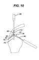
- FIG. 10 is a side elevation view of the procedure of FIG. 8 showing an outer body of a suture anchor being passed beneath the tendon to the bone hole;
- FIG. 11 is a side elevation view of the procedure of FIG. 8 showing the outer body being driven into the bone hole;
- FIG. 12 is a side elevation view of the procedure of FIG. 8 showing the outer body positioned in the bone hole with a guide wire passing out through the tendon;
- FIG. 13 is a side elevation view of the procedure of FIG. 8 showing an inner body of the suture anchor having a pair of suture limbs extending therefrom and a cannulated driver therefor being passed down the guide wire to engage the inner body;
- FIG. 14 is a perspective view of a humerus and a third embodiment of an instrument set and procedure according to the present invention , wherein a spinal needle has been passed through the tendon to a desired location of placing a suture anchor;
- FIG. 15A and FIG. 15B are perspective views of a suture anchor having side slots for the procedure of FIG. 14 and a holding tool for the suture anchor;
- FIG. 16 is a perspective view of the procedure of FIG. 14 showing the suture anchor being passed beneath the tendon;
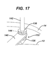
- FIG. 17 is a perspective view of a humerus and a fourth embodiment of an instrument set and procedure according to the present invention showing a suture anchor which has been passed under the tendon being driven into the humerus via a driver passed through the tendon;
- FIG. 18 is a side elevation view of a fifth embodiment of an instrument set according to the present invention in which a driver provides torque to a suture anchor laterally rather than axially.
- FIG. 1 depicts a humerus 10 having a humeral head 12 and a tendon 14 attached to the humeral head 12.
- the tendon 14 has a footprint 16 where it attaches to the humeral head 12 and it can be seen that a portion 18 of the footprint 16 has come detached.
- the space between the tendon 14 and the humeral head 12 is exaggerated for clarity.
- FIG. 2 depicts and a suture anchor 20 and instruments 22 for placement of the suture anchor 20 into the humeral head 12 beneath the detached portion 18 of the tendon footprint 16.
- the instruments 22 include a first driver 24, an awl head 26 and a second driver 28.
- the first driver 24 has an elongated shaft 30 and terminates at its distal end 32 with threads 34 and a sharp point 36.
- the awl head 26 has a threaded opening 38 at its proximal end 40 and a conical section 42 at its distal end 44.
- the threads 34 of the first driver 24 mate with the threaded opening 38 of the awl head 26.
- the second driver 28 comprises an elongated shaft 46 and near its distal end 48 has a hexagonal cross section 50 and terminates in a sharp point 52.
- the suture anchor 20 has a distal end 54, proximal end 56, a threaded outer surface 58 and a hexagonal opening 60 at its proximal end 56 which mates with the hexagonal portion 50 of the second driver 28.
- a pair of sutures 62 extend from the suture anchor 20.
- a surgeon inserts the point 36 of the first driver 24 through the tendon 14 and locates the point 36 at a location on the humeral head 12 at which the surgeon desires to implant the suture anchor 20.
- the point 36 is malleted slightly into the humeral head 12 to make a defect.
- a small amount of biocompatible dye can be carried by the point 36 which is then transferred to the bone during malleting to ease later finding the defect visually.
- a grasper 64 having the awl head 26 attached thereto is inserted under the tendon 14 and the awl head distal end 44 is placed into the defect made by the first driver 24.
- the first driver 24 is threaded into the awl head 26 and the grasper 64 is removed.
- the awl head 26 is then malleted into the humeral head 12 via the first driver 24 (see specifically FIG. 4 ) to create a hole 66 for receipt of the suture anchor 20.
- the awl head 26 is then held by the grasper 64, detached from the first driver 24 and removed (see specifically FIG. 5 ).
- the suture anchor 20 is passed under the tendon 14 and position at the hole 66 via the grasper 64.
- the second driver 28 is passed through the tendon 14, preferably through the same location as which the first driver was passed, and engages the suture anchor 20 (see specifically FIG. 6 ).
- the anchor 20 is then driven into the hole 66 via the second driver 28. Completion of the repair can then be affected now that an anchor 20 is successfully located beneath the tendon 14.
- the sutures 62 can be passed through the tendon 14 in different locations via a suture grasper (not shown) and then tensioned and knotted above the tendon 14 to hold the tendon 14 against the humeral head 12.
- each of the drivers 24 and 28 are of the minimum diameter necessary for strength such that minimal damage is caused to the tendon 14 as they are passed therethrough. Preferably they have diameters, at least of the portion passing through the tendon 14, of less than 4mm and more preferably less than 3mm.
- the features (namely the threads 34 and hexagonal cross section 50) of the first and second drivers 24 and 28 are combined into a single driver so only one pass need be made through the tendon 14.
- the suture anchor 20 can be formed of any biocompatible material such as stainless steel or a bioabsorbable polymer.
- BIOCRYL RAPIDE available from DePuy Mitek, Inc. of Raynham, MA.
- BIOCRYL RAPIDE is a bioabsorbable polymer formed of homogenous blend of TriCalcium Phosphate (TCP) and Polylactic/polyglycolic Acid (PLGA).
- TCP TriCalcium Phosphate
- PLGA Polylactic/polyglycolic Acid
- a threaded anchor 20 is disclosed the invention is not so limited and other anchor types, such as a push-in anchor, could also be employed.
- An anchor outer body 76 has external threads 78, a lateral aperture 80 and an axial opening 82 at a proximal end 84 of the anchor outer body 76.
- the axial opening has a distal hexagonal section 86 which mates with the hexagonal cross section 72 of the awl 68 and also has a proximal threaded portion 88.
- the anchor out body 76 is passed under the tendon 14 via a passing stick 90 inserted through the lateral aperture 80 and the awl 68 is then engaged to the anchor outer body 76 via the hexagonal section 86. With the passing stick 90 removed, the awl is used to drive the anchor outer body 76 into the humeral head 12 at the pilot hole 74.
- a guide wire 92 is left extending out of the anchor body and is withdrawn through the tendon 14 as the awl 68 is removed. It is preferably held in the anchor body by friction to allow easy removal later during the procedure.
- a cannulated inner anchor 94 can then be passed down over the guidewire 92 to engage the threaded portion 88 of the anchor outer body 76.
- the inner anchor 94 comprises a threaded outer surface 96, a hexagonal proximal opening 98, an axial cannulation 100 for receiving the guide wire 92, a suture attachment 102 and a pair of suture ends 104 extending therefrom.
- the inner anchor 94 is loaded onto a driver 106 having a distal hexagonal portion 108 and a cannulation 110 for receiving the guide wire 92.
- the guide wire 92 is threaded into the cannulations 100 and 110 and the inner anchor 94 is passed down the guide wire 92 to mate with the threaded section 88 of the anchor outer body 76.
- connection between the inner anchor 94 and outer body 76 is shown as threaded, other connection types are possible as for instance a snap-fit with radially extending barbs on the inner anchor 94 engaging a lip on the outer body 76 to prevent proximal withdrawal of the inner anchor 94.
- the driver 106 and guide wire 92 are then removed leaving the inner anchor 94 affixed to the humeral head 12 beneath the tendon 14 with the pair of suture ends 104 passing through the tendon 14.
- FIGS. 14 to 16 illustrate a further embodiment of the invention in which a push-in anchor 112 comprises a sharp distal tip 114, barbed exterior ridges 116 for enhanced fixation in bone, and an axial cannulation 118 which has a full length side opening 120.
- a grasper 122 has a semi-circular cut-out 124 at its distal end 126 adapted to snap fit with the anchor 112.
- a surgeon places a needle 128, such as a spinal needle, through the tendon 14 and engages the humeral head 12 at a desired location for placement of the anchor 112.
- FIG. 17 illustrates a similar embodiment in which a push-in anchor 132, having a sharp distal tip 134, barbed ridges 136 and a proximal tool receiving opening 138 is manipulated with a grasper 140 similar to the grasper 122.
- a driver 142 has a sharp distal tip 144 which is first used to punch a small pilot hole into the humeral head 12 at the desired location for placing the anchor132. Then the anchor 132 is slid under the tendon 14 and positioned with its tip 134 in the hole. The driver tip 144 engages the opening 138 in the anchor 132 and the anchor 132 is then malleted into the humeral head 12.
- FIG.18 illustrates another alternative for engaging a threaded anchor 146 and a driver 148 having an anchor engagement 150, such as a hex head, which engages the anchor 146 from the side rather than axially.
- an anchor engagement 150 such as a hex head
- the driver could have a simple ratchet mechanism 152 to allow it to apply torque to the anchor 146 through the engagement 150 and cause it to spiral into bone beneath a tendon.
- the driver 142 could then be used for downward force and would not have to supply rotational force.
- an electric drive in which a rotating shaft engages a worm gear or similar gear connected to the engagement 150 to translate the rotation into the proper axis for rotating the anchor 146.
- Other drive mechanisms could include a chain and sprocket or belt drive.
Landscapes
- Health & Medical Sciences (AREA)
- Surgery (AREA)
- Life Sciences & Earth Sciences (AREA)
- Biomedical Technology (AREA)
- Nuclear Medicine, Radiotherapy & Molecular Imaging (AREA)
- Engineering & Computer Science (AREA)
- Rheumatology (AREA)
- Heart & Thoracic Surgery (AREA)
- Medical Informatics (AREA)
- Molecular Biology (AREA)
- Animal Behavior & Ethology (AREA)
- General Health & Medical Sciences (AREA)
- Public Health (AREA)
- Veterinary Medicine (AREA)
- Surgical Instruments (AREA)
Abstract
Description
- The present application relates to systems and methods for performing a repair of a partial thickness rotator cuff tear.
- A PASTA (partial articular surface tendon avulsion) lesion in a rotator cuff of a shoulder can be particularly difficult to repair. The rotator cuff comprises a group of muscles which surround the shoulder and tendons which attach those muscles to the humeral head. The tendons have a footprint where they attach to the humeral head and in a PASTA lesion a portion of the tendon's footprint becomes detached from the humeral head. Such lesions are most commonly found on the supraspinatus tendon.
- One option for treatment is completion of the tear and repair using standard techniques for a full thickness tear. Preservation of the existing attachment is thus lost and the entire tendon must be reattached. Another option comprises passing a suture anchor through the tendon and into the humeral head, passing suture through the tendon and tying down the tendon to effect reattachment. This causes further trauma to the tendon.
- The present invention provides systems and methods for repairing a PASTA lesion which provides advantages over current treatment options.
- A method, according to the present invention, provides for attaching a partially torn rotator cuff tendon to its associated humeral head. The method comprises the steps of: passing a positional guide through the tendon toward the humeral head at a target site; positioning a suture anchor between the humeral head and the tendon at the target site by passing the suture anchor laterally under the tendon; driving the suture anchor into the humeral head; and passing suture from the suture anchor and through the tendon to attach the tendon to the humeral head at the target site.
- Preferably, the positional guide is a needle.
- In one aspect of the invention, the step of driving the suture anchor into the humeral head comprises rotating the suture anchor via a tool inserted laterally between the tendon and the humeral head. The tool could employ a ratchet drive.
- In another aspect of the invention, the step of driving the suture anchor comprises passing a driver over the positional guide and through the tendon to engage the suture anchor. The suture anchor can be threaded such that the driver rotates the suture anchor into the humeral head, or the driver can merely push or mallet the suture anchor into the humeral head.
- In one aspect of the invention, the suture anchor comprises a first portion and a second portion which can assemble with each other and wherein the step of positioning the suture anchor at the target site comprises the steps of passing the first portion and the second portion in a disassembled state laterally under the tendon and then assembling the first portion to the second portion around the positional guide. Preferably, the positional guide is engaged with the humeral head during the step of assembling the first portion to the second portion.
- Preferably, the step of passing an awl head laterally under the tendon to the target site and engaging the awl head against the humeral head via the positional guide. The awl head can then be driven into the humeral head to create a bone hole. Preferably, the positional guide comprises a threaded distal tip and the step of driving the awl head into the humeral head comprises engaging the awl head with the threaded distal tip of the positional guide, impacting the awl head via the positional guide to create the bone hole and then disengaging the awl head from the positional guide by unthreading the positional guide therefrom. Then the suture anchor can be driven into the humeral head comprises inserting the suture anchor into the bone hole.
- One aspect of the invention involves inserting an inner portion into the suture anchor, the inner portion passing through the tendon and into a recess in the suture anchor and engaging it therein. Preferably, the inner portion has at least one suture attached thereto.
- A suture anchor kit according to the present invention comprises a suture anchor having at least one suture limb extending therefrom, a distal end for entering bone, an opposite proximal end and a side between the distal end and proximal end. A suture anchor passing tool is adapted to grasp the suture anchor side.
- Preferably the passing tool has a height adjacent the suture anchor and over a length thereof sufficient to pass the suture anchor under a tendon in a rotator cuff and wherein the height is less than a length of the suture anchor between its distal end and proximal end.
- In one aspect of the invention the suture anchor has an aperture in its side and the tool has a distal tip sized to fit within the aperture whereby to grasp the anchor.
- Preferably the suture anchor kit according further comprises instructions for use which include an instruction to pass the suture anchor under a tendon in a rotator cuff.
- A suture anchor kit according to the present invention comprises a positional guide adapted to pass through a rotator cuff tendon, a suture anchor, a driver adapted to drive the suture anchor into the humeral head; and instructions for positioning the suture anchor a target site by passing the suture anchor laterally underneath a rotator cuff tendon to intercept the positional guide which is passed through the rotator cuff tendon.
- A suture anchor kit according to the present invention comprises a positional guide adapted to pass through a rotator cuff tendon, a suture anchor, a driver adapted to drive the suture anchor into the humeral head, and wherein the driver engages laterally with the suture anchor whereby to allow the suture anchor and the driver to be placed at a target site under a rotator cuff tendon by passing them laterally underneath the rotator cuff tendon. The driver can comprise a ratchet mechanism. The driver can also comprise a powered rotational drive head adapted to rotate the suture anchor about a central axis thereof.
- A suture anchor kit according to the present invention comprises a positional guide adapted to pass through a rotator cuff tendon, a suture anchor having a central bore through a central axis thereof, the bore being open laterally whereby to be engageable laterally with the positional guide at a target site beneath the rotator cuff tendon; and a driver adapted to drive the suture anchor into the humeral head.
- The suture anchor can comprises a first lateral portion and a second lateral portion, the first lateral portion and second lateral portion engageable with each other laterally at a target site beneath a rotator cuff tendon with the positional guide within the central bore.
- A suture anchor kit according to the present invention comprises a longitudinally extended positional guide having a sharp distal tip adapted to pass through a rotator cuff tendon, an awl head threadably engageable with the distal tip of the positional guide and adapted to form a bone hole in a humeral head, a suture anchor, and a driver adapted to insert the suture anchor into the bone hole.
- Preferably a manipulator is provided which is engagable laterally with at least one of the suture anchor and awl, whereby to allow insertion thereof underneath the rotator cuff tendon. Preferably, a suture extends from the anchor and a suture engaging notch is provided in one of the driver or the positional guide whereby to allow capture of the suture in the suture engaging notch and passage of the suture through the rotator cuff tendon.
- The following is a list of embodiments which are or may be claimed:
- Embodiment 1. A method of attaching a partially torn rotator cuff tendon to its associated humeral head, the method comprising the steps of:
- passing a positional guide through the tendon toward the humeral head at a target site;
- positioning a suture anchor between the humeral head and the tendon at the target site by passing the suture anchor laterally under the tendon;
- driving the suture anchor into the humeral head; and
- passing suture from the suture anchor and through the tendon to attach the tendon to the humeral head at the target site.
- Embodiment 2. A method according to embodiment 1 wherein the positional guide is a needle.
- Embodiment 3. A method according to embodiment 1 wherein the step of driving the suture anchor into the humeral head comprises rotating the suture anchor via a tool inserted laterally between the tendon and the humeral head.
- Embodiment 4. A method according to embodiment 3 wherein the tool employs a ratchet drive.
- Embodiment 5. A method according to embodiment 1 wherein the step of driving the suture anchor comprises passing a driver over the positional guide and through the tendon to engage the suture anchor.
- Embodiment 6. A method according to embodiment 5 wherein the suture anchor is threaded and the driver rotates the suture anchor into the humeral head.
- Embodiment 7. A method according to embodiment 5 wherein the driver pushes the suture anchor into the humeral head.
- Embodiment 8. A method according to embodiment 1 wherein the suture anchor comprises a first portion and a second portion which can assemble with each other and wherein the step of positioning the suture anchor at the target site comprises the steps of passing the first portion and the second portion in a disassembled state laterally under the tendon and then assembling the first portion to the second portion around the positional guide.
- Embodiment 9. A method according to embodiment 8 wherein the positional guide is engaged with the humeral head during the step of assembling the first portion to the second portion.
-
Embodiment 10. A method according to embodiment 1 and further comprising the step of passing an awl head laterally under the tendon to the target site and engaging the awl head against the humeral head via the positional guide. - Embodiment 11. A method according to
embodiment 10 and further comprising the step of driving the awl head into the humeral head to create a bone hole. -
Embodiment 12. A method according to embodiment 11 wherein the positional guide comprises a threaded distal tip and wherein the step of driving the awl head into the humeral head comprises engaging the awl head with the threaded distal tip of the positional guide, impacting the awl head via the positional guide to create the bone hole and then disengaging the awl head from the positional guide by unthreading the positional guide therefrom. - Embodiment 13. A method according to embodiment 11 and wherein the step of driving the suture anchor into the humeral head comprises inserting the suture anchor into the bone hole.
-
Embodiment 14. A method according to embodiment 1 and further comprising the step of inserting an inner portion into the suture anchor, the inner portion passing through the tendon and into a recess in the suture anchor and engaging it therein. - Embodiment 15. A method according to
embodiment 14 wherein the inner portion has at least one suture attached thereto. -
FIG. 1 is a side elevation view of a humerus and a tendon of the rotator cuff showing a PASTA lesion; -
FIG. 2 is a side elevation view of an instrument set according to the present invention; -
FIG. 3 is a side elevation view of the humerus ofFIG. 1 and showing a step in a procedure according to the present invention in which an awl ofFIG. 2 is positioned underneath the tendon and a first driver ofFIG. 2 is passed through the tendon to engage the awl; -
FIG. 4 is a side elevation view of the procedure ofFIG. 3 showing the awl creating a bone hole in the humerus beneath the tendon; -
FIG. 5 is a side elevation view of the procedure ofFIG. 3 showing the bone hole and showing awl and first driver being removed from the site; -
FIG. 6 is a side elevation view of the procedure ofFIG. 3 showing a suture anchor ofFIG. 2 being positioned beneath the tendon at the bone hole and a second driver ofFIG. 2 being passed through the tendon to engage the suture anchor; -
FIG. 7 is a side elevation view of the procedure ofFIG. 3 showing the anchor being driven into the bone hole; -
FIG. 8 is a side elevation view of a humerus and a second embodiment of an instrument set and procedure according to the present invention, wherein an awl is passed through the tendon; -
FIG. 9 is a side elevation view of the procedure ofFIG. 8 showing the awl tapping a bone hole in the humerus beneath the tendon; -
FIG. 10 is a side elevation view of the procedure ofFIG. 8 showing an outer body of a suture anchor being passed beneath the tendon to the bone hole; -
FIG. 11 is a side elevation view of the procedure ofFIG. 8 showing the outer body being driven into the bone hole; -
FIG. 12 is a side elevation view of the procedure ofFIG. 8 showing the outer body positioned in the bone hole with a guide wire passing out through the tendon; -
FIG. 13 is a side elevation view of the procedure ofFIG. 8 showing an inner body of the suture anchor having a pair of suture limbs extending therefrom and a cannulated driver therefor being passed down the guide wire to engage the inner body; -
FIG. 14 is a perspective view of a humerus and a third embodiment of an instrument set and procedure according to the present invention , wherein a spinal needle has been passed through the tendon to a desired location of placing a suture anchor; -
FIG. 15A and FIG. 15B are perspective views of a suture anchor having side slots for the procedure ofFIG. 14 and a holding tool for the suture anchor; -
FIG. 16 is a perspective view of the procedure ofFIG. 14 showing the suture anchor being passed beneath the tendon; -
FIG. 17 is a perspective view of a humerus and a fourth embodiment of an instrument set and procedure according to the present invention showing a suture anchor which has been passed under the tendon being driven into the humerus via a driver passed through the tendon; and -
FIG. 18 is a side elevation view of a fifth embodiment of an instrument set according to the present invention in which a driver provides torque to a suture anchor laterally rather than axially. -
FIG. 1 depicts ahumerus 10 having ahumeral head 12 and atendon 14 attached to thehumeral head 12. Thetendon 14 has afootprint 16 where it attaches to thehumeral head 12 and it can be seen that aportion 18 of thefootprint 16 has come detached. The space between thetendon 14 and thehumeral head 12 is exaggerated for clarity. -
FIG. 2 depicts and asuture anchor 20 and instruments 22 for placement of thesuture anchor 20 into thehumeral head 12 beneath thedetached portion 18 of thetendon footprint 16. The instruments 22 include afirst driver 24, anawl head 26 and asecond driver 28. Thefirst driver 24 has an elongatedshaft 30 and terminates at itsdistal end 32 withthreads 34 and asharp point 36. Theawl head 26 has a threadedopening 38 at itsproximal end 40 and aconical section 42 at itsdistal end 44. Thethreads 34 of thefirst driver 24 mate with the threadedopening 38 of theawl head 26. Thesecond driver 28 comprises anelongated shaft 46 and near itsdistal end 48 has ahexagonal cross section 50 and terminates in asharp point 52. Thesuture anchor 20 has adistal end 54,proximal end 56, a threadedouter surface 58 and ahexagonal opening 60 at itsproximal end 56 which mates with thehexagonal portion 50 of thesecond driver 28. A pair ofsutures 62 extend from thesuture anchor 20. - Turning also now to
FIGS. 3 to 7 , to effect a repair a surgeon inserts thepoint 36 of thefirst driver 24 through thetendon 14 and locates thepoint 36 at a location on thehumeral head 12 at which the surgeon desires to implant thesuture anchor 20. Thepoint 36 is malleted slightly into thehumeral head 12 to make a defect. A small amount of biocompatible dye can be carried by thepoint 36 which is then transferred to the bone during malleting to ease later finding the defect visually. Then as depicted inFIG. 3 specifically agrasper 64 having theawl head 26 attached thereto is inserted under thetendon 14 and the awl headdistal end 44 is placed into the defect made by thefirst driver 24. Thefirst driver 24 is threaded into theawl head 26 and thegrasper 64 is removed. Theawl head 26 is then malleted into thehumeral head 12 via the first driver 24 (see specificallyFIG. 4 ) to create ahole 66 for receipt of thesuture anchor 20. Theawl head 26 is then held by thegrasper 64, detached from thefirst driver 24 and removed (see specificallyFIG. 5 ). - Now that the
hole 66 has been prepared thesuture anchor 20 is passed under thetendon 14 and position at thehole 66 via thegrasper 64. Thesecond driver 28 is passed through thetendon 14, preferably through the same location as which the first driver was passed, and engages the suture anchor 20 (see specificallyFIG. 6 ). Theanchor 20 is then driven into thehole 66 via thesecond driver 28. Completion of the repair can then be affected now that ananchor 20 is successfully located beneath thetendon 14. For instance, thesutures 62 can be passed through thetendon 14 in different locations via a suture grasper (not shown) and then tensioned and knotted above thetendon 14 to hold thetendon 14 against thehumeral head 12. - Preferably each of the
drivers tendon 14 as they are passed therethrough. Preferably they have diameters, at least of the portion passing through thetendon 14, of less than 4mm and more preferably less than 3mm. In an alternate embodiment not shown, the features (namely thethreads 34 and hexagonal cross section 50) of the first andsecond drivers tendon 14. Thesuture anchor 20 can be formed of any biocompatible material such as stainless steel or a bioabsorbable polymer. The HEALIX BR dual threaded suture anchor in BIOCRYL RAPIDE available from DePuy Mitek, Inc. of Raynham, MA. BIOCRYL RAPIDE is a bioabsorbable polymer formed of homogenous blend of TriCalcium Phosphate (TCP) and Polylactic/polyglycolic Acid (PLGA). Although, a threadedanchor 20 is disclosed the invention is not so limited and other anchor types, such as a push-in anchor, could also be employed. - Turning now to
FIGS. 8 to 13 which illustrate an alternative embodiment of the invention, anawl 68 having a sharpdistal tip 70 and ahexagonal cross section 72 proximal thereof penetrates thetendon 14 and is malleted into thehumeral head 12 to form apilot hole 74. An anchorouter body 76 hasexternal threads 78, alateral aperture 80 and anaxial opening 82 at a proximal end 84 of the anchorouter body 76. The axial opening has a distalhexagonal section 86 which mates with thehexagonal cross section 72 of theawl 68 and also has a proximal threadedportion 88. The anchor outbody 76 is passed under thetendon 14 via a passingstick 90 inserted through thelateral aperture 80 and theawl 68 is then engaged to the anchorouter body 76 via thehexagonal section 86. With the passingstick 90 removed, the awl is used to drive the anchorouter body 76 into thehumeral head 12 at thepilot hole 74. Aguide wire 92 is left extending out of the anchor body and is withdrawn through thetendon 14 as theawl 68 is removed. It is preferably held in the anchor body by friction to allow easy removal later during the procedure. A cannulatedinner anchor 94 can then be passed down over theguidewire 92 to engage the threadedportion 88 of the anchorouter body 76. Theinner anchor 94 comprises a threadedouter surface 96, a hexagonalproximal opening 98, anaxial cannulation 100 for receiving theguide wire 92, a suture attachment 102 and a pair of suture ends 104 extending therefrom. Theinner anchor 94 is loaded onto adriver 106 having a distalhexagonal portion 108 and acannulation 110 for receiving theguide wire 92. Theguide wire 92 is threaded into thecannulations inner anchor 94 is passed down theguide wire 92 to mate with the threadedsection 88 of the anchorouter body 76. Although the connection between theinner anchor 94 andouter body 76 is shown as threaded, other connection types are possible as for instance a snap-fit with radially extending barbs on theinner anchor 94 engaging a lip on theouter body 76 to prevent proximal withdrawal of theinner anchor 94. Thedriver 106 and guidewire 92 are then removed leaving theinner anchor 94 affixed to thehumeral head 12 beneath thetendon 14 with the pair of suture ends 104 passing through thetendon 14. -
FIGS. 14 to 16 illustrate a further embodiment of the invention in which a push-inanchor 112 comprises a sharpdistal tip 114, barbedexterior ridges 116 for enhanced fixation in bone, and anaxial cannulation 118 which has a fulllength side opening 120. Agrasper 122 has a semi-circular cut-out 124 at itsdistal end 126 adapted to snap fit with theanchor 112. To effect a repair of a PASTA lesion a surgeon places aneedle 128, such as a spinal needle, through thetendon 14 and engages thehumeral head 12 at a desired location for placement of theanchor 112. Theanchor 112, via thegrasper 122, is slid under thetendon 14 and adjusted to engage theneedle 128 in thecannulation 118 through itsside opening 120. Theopening 120 can be sized to effect a snap-fit of theanchor 112 to theneedle 128. A cannulateddriver 130 is then passed down over theneedle 128 to engage theanchor 112 at itsproximal end 132 so that theanchor 112 can be malleted into thehumeral head 12. -
FIG. 17 illustrates a similar embodiment in which a push-inanchor 132, having a sharp distal tip 134,barbed ridges 136 and a proximaltool receiving opening 138 is manipulated with agrasper 140 similar to thegrasper 122. Here, adriver 142 has a sharpdistal tip 144 which is first used to punch a small pilot hole into thehumeral head 12 at the desired location for placing the anchor132. Then theanchor 132 is slid under thetendon 14 and positioned with its tip 134 in the hole. Thedriver tip 144 engages theopening 138 in theanchor 132 and theanchor 132 is then malleted into thehumeral head 12. -
FIG.18 illustrates another alternative for engaging a threaded anchor 146 and adriver 148 having ananchor engagement 150, such as a hex head, which engages the anchor 146 from the side rather than axially. For an open procedure the driver could have asimple ratchet mechanism 152 to allow it to apply torque to the anchor 146 through theengagement 150 and cause it to spiral into bone beneath a tendon. Thedriver 142 could then be used for downward force and would not have to supply rotational force. For arthroscopic procedures it would be preferred to have an electric drive in which a rotating shaft engages a worm gear or similar gear connected to theengagement 150 to translate the rotation into the proper axis for rotating the anchor 146. Other drive mechanisms could include a chain and sprocket or belt drive. - Various modifications and alterations of this invention will be apparent to those skilled in the art without departing from the scope and spirit of this invention. It should be understood that the invention is not limited to the embodiments disclosed herein, and that the claims should be interpreted as broadly as the prior art allows. For instance, alternative grasper designs may be employed such as where a distal tip thereof fits into a hole in the anchor and is held by friction, snap-fit, temporary adhesive, threading, frangible connection, magnetism or the like. Such enhancements can be employed with other graspers. Further, the anchor can have indentations or flats on its outer surface to more easily allow grasping by a jaw-type grasper or snap-fit external grasper such as in
FIG. 15B etc.
Claims (13)
- A suture anchor kit comprising:a suture anchor having at least one suture limb extending therefrom, the suture anchor comprising a distal end for entering bone, an opposite proximal end and a side between the distal end and proximal end;a suture anchor passing tool adapted to grasp the suture anchor side.
- A suture anchor kit according to claim 1 wherein the passing tool has a height adjacent the suture anchor and over a length thereof sufficient to pass the suture anchor under a tendon in a rotator cuff and wherein the height is less than a length of the suture anchor between its distal end and proximal end.
- A suture anchor kit according to claim 1 or 2 wherein the suture anchor has an aperture in its side and wherein the tool has a distal tip sized to fit within the aperture whereby to grasp the anchor.
- A suture anchor kit according to claim 1, 2 or 3 and further comprising instructions for use which include an instruction to pass the suture anchor under a tendon in a rotator cuff.
- A suture anchor kit comprising:a positional guide adapted to pass through a rotator cuff tendon;a suture anchor;a driver adapted to drive the suture anchor into the humeral head; andinstructions for positioning the suture anchor a target site by passing the suture anchor laterally underneath a rotator cuff tendon to intercept the positional guide which is passed through the rotator cuff tendon.
- A suture anchor kit comprising:a positional guide adapted to pass through a rotator cuff tendon;a suture anchor;
a driver adapted to drive the suture anchor into the humeral head; and
wherein the driver engages laterally with the suture anchor whereby to allow the suture anchor and the driver to be placed at a target site under a rotator cuff tendon by passing them laterally underneath the rotator cuff tendon. - A suture anchor kit according to claim 6 and wherein the driver comprises a ratchet mechanism.
- A suture anchor kit according to claim 6 wherein the driver comprises a powered rotational drive head adapted to rotate the suture anchor about a central axis thereof.
- A suture anchor kit comprising:a positional guide adapted to pass through a rotator cuff tendon;
a suture anchor having a central bore through a central axis thereof, the bore being open laterally whereby to be engageable laterally with the positional guide at a target site beneath the rotator cuff tendon; and
a driver adapted to drive the suture anchor into the humeral head. - A suture anchor kit according to claim 9 wherein the suture anchor comprises a first lateral portion and a second lateral portion, the first lateral portion and second lateral portion engageable with each other laterally at a target site beneath a rotator cuff tendon with the positional guide within the central bore.
- A suture anchor kit comprising:a longitudinally extended positional guide having a sharp distal tip adapted to pass through a rotator cuff tendon;an awl head threadably engageable with the distal tip of the positional guide and adapted to form a bone hole in a humeral head;a suture anchor; anda driver adapted to insert the suture anchor into the bone hole.
- A suture anchor kit according to claim 11 and further comprising a manipulator engagable laterally with at least one of the suture anchor and awl, whereby to allow insertion thereof underneath the rotator cuff tendon.
- A suture anchor kit according to claim 11 or 12 and further comprising a suture extending from the anchor and a suture engaging notch in one of the driver or the positional guide whereby to allow capture of the suture in the suture engaging notch and passage of the suture through the rotator cuff tendon.
Applications Claiming Priority (1)
| Application Number | Priority Date | Filing Date | Title |
|---|---|---|---|
| US25636209P | 2009-10-30 | 2009-10-30 |
Publications (2)
| Publication Number | Publication Date |
|---|---|
| EP2332470A1 true EP2332470A1 (en) | 2011-06-15 |
| EP2332470B1 EP2332470B1 (en) | 2020-06-24 |
Family
ID=43597981
Family Applications (1)
| Application Number | Title | Priority Date | Filing Date |
|---|---|---|---|
| EP10251881.8A Active EP2332470B1 (en) | 2009-10-30 | 2010-10-29 | Partial thickness rotator cuff repair system |
Country Status (7)
| Country | Link |
|---|---|
| US (2) | US8523903B2 (en) |
| EP (1) | EP2332470B1 (en) |
| JP (1) | JP5788163B2 (en) |
| CN (1) | CN102048563B (en) |
| AU (3) | AU2010236112B8 (en) |
| BR (1) | BRPI1010405B1 (en) |
| CA (1) | CA2718890A1 (en) |
Families Citing this family (21)
| Publication number | Priority date | Publication date | Assignee | Title |
|---|---|---|---|---|
| US20130085528A1 (en) * | 2011-09-30 | 2013-04-04 | Depuy Mitek, Inc. | Knotless suture anchor |
| US9237894B2 (en) * | 2013-01-31 | 2016-01-19 | Depuy Mitek, Llc | Methods and devices for forming holes in bone to stimulate bone growth |
| US9913637B2 (en) | 2013-03-13 | 2018-03-13 | DePuy Synthes Products, Inc. | Soft tissue fixation system |
| US9901333B2 (en) | 2013-03-13 | 2018-02-27 | DePuy Synthes Products, Inc. | Soft tissue fixation system |
| CA2925313C (en) | 2013-09-27 | 2017-01-10 | Release Medical, Inc. | Tissue incision device |
| US10856966B2 (en) | 2014-10-23 | 2020-12-08 | Medos International Sarl | Biceps tenodesis implants and delivery tools |
| US10076374B2 (en) | 2014-10-23 | 2018-09-18 | Medos International Sárl | Biceps tenodesis delivery tools |
| US10034742B2 (en) | 2014-10-23 | 2018-07-31 | Medos International Sarl | Biceps tenodesis implants and delivery tools |
| US10729419B2 (en) | 2014-10-23 | 2020-08-04 | Medos International Sarl | Biceps tenodesis implants and delivery tools |
| US10751161B2 (en) | 2014-10-23 | 2020-08-25 | Medos International Sárl | Biceps tenodesis anchor implants |
| CN104367356B (en) * | 2014-12-01 | 2016-08-17 | 上海凯利泰医疗科技股份有限公司 | A kind of for takeing on tunnel sighting device and the method for sight that sleeve is repaired |
| US9693856B2 (en) | 2015-04-22 | 2017-07-04 | DePuy Synthes Products, LLC | Biceps repair device |
| US10617406B2 (en) * | 2015-06-30 | 2020-04-14 | Smith & Nephew, Inc. | Suture anchor system with threaded plug |
| US10231824B2 (en) | 2016-04-08 | 2019-03-19 | Medos International Sárl | Tenodesis anchoring systems and tools |
| US10231823B2 (en) | 2016-04-08 | 2019-03-19 | Medos International Sarl | Tenodesis implants and tools |
| US10238444B2 (en) * | 2016-05-10 | 2019-03-26 | DePuy Synthes Products, Inc. | Insertion tool for flip anchor cable system insertion |
| WO2017201216A1 (en) * | 2016-05-18 | 2017-11-23 | Orthonoble Inc. | Disposable instrument nosepieces for repairing soft tissue to bone coupling |
| EP3644868A1 (en) * | 2017-06-26 | 2020-05-06 | ConMed Corporation | Multiple suture passing device |
| CN112294491B (en) * | 2020-03-19 | 2023-01-31 | 南通市第一人民医院 | Minimally invasive comfortable urinary incontinence sling device and application thereof |
| CN112353442B (en) * | 2020-11-11 | 2022-06-10 | 贺业腾 | An anchor system for rotator cuff injury repair |
| CN114917055B (en) * | 2022-07-20 | 2023-02-07 | 北京天星博迈迪医疗器械有限公司 | A prefabricated artificial shoulder joint capsule |
Citations (2)
| Publication number | Priority date | Publication date | Assignee | Title |
|---|---|---|---|---|
| US20030130694A1 (en) * | 1999-12-02 | 2003-07-10 | Ray Bojarski | Soft tissue attachment and repair |
| WO2010132310A1 (en) * | 2009-05-12 | 2010-11-18 | Foundry Newco Xi, Inc. | Methods and devices to treat diseased or injured musculoskeletal tissue |
Family Cites Families (21)
| Publication number | Priority date | Publication date | Assignee | Title |
|---|---|---|---|---|
| US5441502A (en) | 1993-02-17 | 1995-08-15 | Mitek Surgical Products, Inc. | System and method for re-attaching soft tissue to bone |
| US6319270B1 (en) | 1996-08-05 | 2001-11-20 | Arthrex, Inc. | Headed bioabsorbable tissue anchor |
| US5948000A (en) | 1996-10-03 | 1999-09-07 | United States Surgical Corporation | System for suture anchor placement |
| US5948001A (en) | 1996-10-03 | 1999-09-07 | United States Surgical Corporation | System for suture anchor placement |
| US5980524A (en) | 1997-06-02 | 1999-11-09 | Innovasive Devices, Inc. | Device for repairing a meniscal tear in a knee and method |
| WO1999059488A1 (en) * | 1998-05-21 | 1999-11-25 | Chan Kwan Ho | Apparatus and method for ligament fixation |
| US5993477A (en) * | 1998-06-25 | 1999-11-30 | Ethicon Endo-Surgery, Inc. | Ultrasonic bone anchor |
| US6096060A (en) * | 1999-05-20 | 2000-08-01 | Linvatec Corporation | Bioabsorbable threaded soft tissue anchor system |
| US6461373B2 (en) * | 2000-05-26 | 2002-10-08 | Arthrex, Inc. | Biointerference screw fixation technique |
| US6887259B2 (en) * | 2000-10-18 | 2005-05-03 | Depuy Mitek, Inc. | Suture anchor system and method of use |
| US6620195B2 (en) * | 2001-04-18 | 2003-09-16 | Medicinelodge, Inc. | Apparatus and method for attaching a graft ligament to a bone |
| US20020183762A1 (en) * | 2001-06-01 | 2002-12-05 | Ams Research Corporation | Bone anchor inserters and methods |
| US7204839B2 (en) | 2002-09-04 | 2007-04-17 | Arthrex, Inc. | Method of using offset drill guide in arthroscopic surgery |
| US7588577B2 (en) * | 2004-07-15 | 2009-09-15 | Wright Medical Technology, Inc. | Guide assembly for intramedullary fixation and method of using the same |
| CA2587683A1 (en) * | 2004-11-15 | 2006-05-26 | Scandius Biomedical, Inc. | Method and apparatus for the repair of a rotator cuff (rtc) tendon or ligament |
| EP1909687A1 (en) * | 2005-07-13 | 2008-04-16 | Boston Scientific Scimed, Inc. | Snap fit sling anchor system and related methods |
| US8758367B2 (en) | 2006-09-05 | 2014-06-24 | Smith & Nephew, Inc. | Anchor delivery system |
| US8758406B2 (en) * | 2007-03-05 | 2014-06-24 | Tomier, Inc. | Tack anchor systems, bone anchor systems, and methods of use |
| US8206389B2 (en) * | 2007-08-31 | 2012-06-26 | Huebner Randall J | Rod-based system for bone fixation |
| US20110238112A1 (en) * | 2009-05-29 | 2011-09-29 | Kim Andrew C | Suture anchor |
| WO2010144992A1 (en) * | 2009-06-16 | 2010-12-23 | Marc Beauchamp | Method and apparatus for arthroscopic rotator cuff repair using transosseous tunnels |
-
2010
- 2010-10-20 US US12/908,261 patent/US8523903B2/en not_active Expired - Fee Related
- 2010-10-26 CA CA2718890A patent/CA2718890A1/en not_active Abandoned
- 2010-10-29 AU AU2010236112A patent/AU2010236112B8/en not_active Ceased
- 2010-10-29 EP EP10251881.8A patent/EP2332470B1/en active Active
- 2010-10-29 JP JP2010243405A patent/JP5788163B2/en not_active Expired - Fee Related
- 2010-10-29 CN CN201010539139.5A patent/CN102048563B/en not_active Expired - Fee Related
- 2010-10-29 BR BRPI1010405-4A patent/BRPI1010405B1/en not_active IP Right Cessation
-
2013
- 2013-07-24 US US13/949,639 patent/US20140031865A1/en not_active Abandoned
-
2015
- 2015-02-25 AU AU2015200957A patent/AU2015200957A1/en not_active Abandoned
-
2017
- 2017-04-07 AU AU2017202295A patent/AU2017202295B2/en not_active Ceased
Patent Citations (2)
| Publication number | Priority date | Publication date | Assignee | Title |
|---|---|---|---|---|
| US20030130694A1 (en) * | 1999-12-02 | 2003-07-10 | Ray Bojarski | Soft tissue attachment and repair |
| WO2010132310A1 (en) * | 2009-05-12 | 2010-11-18 | Foundry Newco Xi, Inc. | Methods and devices to treat diseased or injured musculoskeletal tissue |
Also Published As
| Publication number | Publication date |
|---|---|
| US20140031865A1 (en) | 2014-01-30 |
| AU2010236112B8 (en) | 2015-07-16 |
| CA2718890A1 (en) | 2011-04-30 |
| BRPI1010405A2 (en) | 2014-01-07 |
| US20110270308A1 (en) | 2011-11-03 |
| BRPI1010405B1 (en) | 2020-10-27 |
| CN102048563B (en) | 2016-03-09 |
| AU2017202295A1 (en) | 2017-04-27 |
| US8523903B2 (en) | 2013-09-03 |
| AU2010236112A1 (en) | 2011-05-19 |
| CN102048563A (en) | 2011-05-11 |
| JP5788163B2 (en) | 2015-09-30 |
| JP2011092741A (en) | 2011-05-12 |
| EP2332470B1 (en) | 2020-06-24 |
| AU2015200957A1 (en) | 2015-03-12 |
| AU2010236112A8 (en) | 2015-07-16 |
| AU2010236112B2 (en) | 2015-03-19 |
| AU2017202295B2 (en) | 2018-05-24 |
Similar Documents
| Publication | Publication Date | Title |
|---|---|---|
| US8523903B2 (en) | Partial thickness rotator cuff repair system and method | |
| US20220273285A1 (en) | Partial thickness rotator cuff repair system and method | |
| US8414613B2 (en) | Medical device and procedure for attaching tissue to bone | |
| AU2005307057B2 (en) | Anchor/suture used for medical procedures | |
| EP2316380B1 (en) | Dual cannula system for partial thickness rotator cuff repair | |
| US6554852B1 (en) | Multi-anchor suture | |
| US20070167950A1 (en) | System and method for attaching soft tissue to bone | |
| US20040267317A1 (en) | Methods for attaching tissue to bone | |
| US20080208253A1 (en) | Self-punching swivel anchor and method for knotless fixation of tissue | |
| JP2022169473A (en) | knotless suture anchor |
Legal Events
| Date | Code | Title | Description |
|---|---|---|---|
| PUAI | Public reference made under article 153(3) epc to a published international application that has entered the european phase |
Free format text: ORIGINAL CODE: 0009012 |
|
| AK | Designated contracting states |
Kind code of ref document: A1 Designated state(s): AL AT BE BG CH CY CZ DE DK EE ES FI FR GB GR HR HU IE IS IT LI LT LU LV MC MK MT NL NO PL PT RO RS SE SI SK SM TR |
|
| AX | Request for extension of the european patent |
Extension state: BA ME |
|
| 17P | Request for examination filed |
Effective date: 20111215 |
|
| 17Q | First examination report despatched |
Effective date: 20130916 |
|
| APBK | Appeal reference recorded |
Free format text: ORIGINAL CODE: EPIDOSNREFNE |
|
| APBN | Date of receipt of notice of appeal recorded |
Free format text: ORIGINAL CODE: EPIDOSNNOA2E |
|
| APBR | Date of receipt of statement of grounds of appeal recorded |
Free format text: ORIGINAL CODE: EPIDOSNNOA3E |
|
| APAF | Appeal reference modified |
Free format text: ORIGINAL CODE: EPIDOSCREFNE |
|
| APBT | Appeal procedure closed |
Free format text: ORIGINAL CODE: EPIDOSNNOA9E |
|
| GRAP | Despatch of communication of intention to grant a patent |
Free format text: ORIGINAL CODE: EPIDOSNIGR1 |
|
| STAA | Information on the status of an ep patent application or granted ep patent |
Free format text: STATUS: GRANT OF PATENT IS INTENDED |
|
| RIC1 | Information provided on ipc code assigned before grant |
Ipc: A61B 17/00 20060101ALI20191108BHEP Ipc: A61B 17/04 20060101AFI20191108BHEP |
|
| INTG | Intention to grant announced |
Effective date: 20191204 |
|
| GRAS | Grant fee paid |
Free format text: ORIGINAL CODE: EPIDOSNIGR3 |
|
| RAP1 | Party data changed (applicant data changed or rights of an application transferred) |
Owner name: DEPUY SYNTHES PRODUCTS, LLC |
|
| GRAA | (expected) grant |
Free format text: ORIGINAL CODE: 0009210 |
|
| STAA | Information on the status of an ep patent application or granted ep patent |
Free format text: STATUS: THE PATENT HAS BEEN GRANTED |
|
| RAP1 | Party data changed (applicant data changed or rights of an application transferred) |
Owner name: DEPUY SYNTHES PRODUCTS, INC. |
|
| AK | Designated contracting states |
Kind code of ref document: B1 Designated state(s): AL AT BE BG CH CY CZ DE DK EE ES FI FR GB GR HR HU IE IS IT LI LT LU LV MC MK MT NL NO PL PT RO RS SE SI SK SM TR |
|
| REG | Reference to a national code |
Ref country code: GB Ref legal event code: FG4D |
|
| REG | Reference to a national code |
Ref country code: CH Ref legal event code: NV Representative=s name: E. BLUM AND CO. AG PATENT- UND MARKENANWAELTE , CH Ref country code: CH Ref legal event code: EP |
|
| REG | Reference to a national code |
Ref country code: DE Ref legal event code: R096 Ref document number: 602010064713 Country of ref document: DE |
|
| REG | Reference to a national code |
Ref country code: AT Ref legal event code: REF Ref document number: 1283105 Country of ref document: AT Kind code of ref document: T Effective date: 20200715 |
|
| REG | Reference to a national code |
Ref country code: IE Ref legal event code: FG4D |
|
| PG25 | Lapsed in a contracting state [announced via postgrant information from national office to epo] |
Ref country code: GR Free format text: LAPSE BECAUSE OF FAILURE TO SUBMIT A TRANSLATION OF THE DESCRIPTION OR TO PAY THE FEE WITHIN THE PRESCRIBED TIME-LIMIT Effective date: 20200925 Ref country code: NO Free format text: LAPSE BECAUSE OF FAILURE TO SUBMIT A TRANSLATION OF THE DESCRIPTION OR TO PAY THE FEE WITHIN THE PRESCRIBED TIME-LIMIT Effective date: 20200924 Ref country code: FI Free format text: LAPSE BECAUSE OF FAILURE TO SUBMIT A TRANSLATION OF THE DESCRIPTION OR TO PAY THE FEE WITHIN THE PRESCRIBED TIME-LIMIT Effective date: 20200624 Ref country code: LT Free format text: LAPSE BECAUSE OF FAILURE TO SUBMIT A TRANSLATION OF THE DESCRIPTION OR TO PAY THE FEE WITHIN THE PRESCRIBED TIME-LIMIT Effective date: 20200624 Ref country code: SE Free format text: LAPSE BECAUSE OF FAILURE TO SUBMIT A TRANSLATION OF THE DESCRIPTION OR TO PAY THE FEE WITHIN THE PRESCRIBED TIME-LIMIT Effective date: 20200624 |
|
| REG | Reference to a national code |
Ref country code: LT Ref legal event code: MG4D |
|
| PG25 | Lapsed in a contracting state [announced via postgrant information from national office to epo] |
Ref country code: LV Free format text: LAPSE BECAUSE OF FAILURE TO SUBMIT A TRANSLATION OF THE DESCRIPTION OR TO PAY THE FEE WITHIN THE PRESCRIBED TIME-LIMIT Effective date: 20200624 Ref country code: HR Free format text: LAPSE BECAUSE OF FAILURE TO SUBMIT A TRANSLATION OF THE DESCRIPTION OR TO PAY THE FEE WITHIN THE PRESCRIBED TIME-LIMIT Effective date: 20200624 Ref country code: BG Free format text: LAPSE BECAUSE OF FAILURE TO SUBMIT A TRANSLATION OF THE DESCRIPTION OR TO PAY THE FEE WITHIN THE PRESCRIBED TIME-LIMIT Effective date: 20200924 Ref country code: RS Free format text: LAPSE BECAUSE OF FAILURE TO SUBMIT A TRANSLATION OF THE DESCRIPTION OR TO PAY THE FEE WITHIN THE PRESCRIBED TIME-LIMIT Effective date: 20200624 |
|
| REG | Reference to a national code |
Ref country code: NL Ref legal event code: MP Effective date: 20200624 |
|
| REG | Reference to a national code |
Ref country code: AT Ref legal event code: MK05 Ref document number: 1283105 Country of ref document: AT Kind code of ref document: T Effective date: 20200624 |
|
| PG25 | Lapsed in a contracting state [announced via postgrant information from national office to epo] |
Ref country code: AL Free format text: LAPSE BECAUSE OF FAILURE TO SUBMIT A TRANSLATION OF THE DESCRIPTION OR TO PAY THE FEE WITHIN THE PRESCRIBED TIME-LIMIT Effective date: 20200624 Ref country code: NL Free format text: LAPSE BECAUSE OF FAILURE TO SUBMIT A TRANSLATION OF THE DESCRIPTION OR TO PAY THE FEE WITHIN THE PRESCRIBED TIME-LIMIT Effective date: 20200624 |
|
| PG25 | Lapsed in a contracting state [announced via postgrant information from national office to epo] |
Ref country code: PT Free format text: LAPSE BECAUSE OF FAILURE TO SUBMIT A TRANSLATION OF THE DESCRIPTION OR TO PAY THE FEE WITHIN THE PRESCRIBED TIME-LIMIT Effective date: 20201026 Ref country code: ES Free format text: LAPSE BECAUSE OF FAILURE TO SUBMIT A TRANSLATION OF THE DESCRIPTION OR TO PAY THE FEE WITHIN THE PRESCRIBED TIME-LIMIT Effective date: 20200624 Ref country code: AT Free format text: LAPSE BECAUSE OF FAILURE TO SUBMIT A TRANSLATION OF THE DESCRIPTION OR TO PAY THE FEE WITHIN THE PRESCRIBED TIME-LIMIT Effective date: 20200624 Ref country code: EE Free format text: LAPSE BECAUSE OF FAILURE TO SUBMIT A TRANSLATION OF THE DESCRIPTION OR TO PAY THE FEE WITHIN THE PRESCRIBED TIME-LIMIT Effective date: 20200624 Ref country code: SM Free format text: LAPSE BECAUSE OF FAILURE TO SUBMIT A TRANSLATION OF THE DESCRIPTION OR TO PAY THE FEE WITHIN THE PRESCRIBED TIME-LIMIT Effective date: 20200624 Ref country code: CZ Free format text: LAPSE BECAUSE OF FAILURE TO SUBMIT A TRANSLATION OF THE DESCRIPTION OR TO PAY THE FEE WITHIN THE PRESCRIBED TIME-LIMIT Effective date: 20200624 Ref country code: RO Free format text: LAPSE BECAUSE OF FAILURE TO SUBMIT A TRANSLATION OF THE DESCRIPTION OR TO PAY THE FEE WITHIN THE PRESCRIBED TIME-LIMIT Effective date: 20200624 |
|
| PG25 | Lapsed in a contracting state [announced via postgrant information from national office to epo] |
Ref country code: IS Free format text: LAPSE BECAUSE OF FAILURE TO SUBMIT A TRANSLATION OF THE DESCRIPTION OR TO PAY THE FEE WITHIN THE PRESCRIBED TIME-LIMIT Effective date: 20201024 Ref country code: PL Free format text: LAPSE BECAUSE OF FAILURE TO SUBMIT A TRANSLATION OF THE DESCRIPTION OR TO PAY THE FEE WITHIN THE PRESCRIBED TIME-LIMIT Effective date: 20200624 Ref country code: SK Free format text: LAPSE BECAUSE OF FAILURE TO SUBMIT A TRANSLATION OF THE DESCRIPTION OR TO PAY THE FEE WITHIN THE PRESCRIBED TIME-LIMIT Effective date: 20200624 |
|
| REG | Reference to a national code |
Ref country code: DE Ref legal event code: R097 Ref document number: 602010064713 Country of ref document: DE |
|
| PG25 | Lapsed in a contracting state [announced via postgrant information from national office to epo] |
Ref country code: DK Free format text: LAPSE BECAUSE OF FAILURE TO SUBMIT A TRANSLATION OF THE DESCRIPTION OR TO PAY THE FEE WITHIN THE PRESCRIBED TIME-LIMIT Effective date: 20200624 |
|
| PLBE | No opposition filed within time limit |
Free format text: ORIGINAL CODE: 0009261 |
|
| STAA | Information on the status of an ep patent application or granted ep patent |
Free format text: STATUS: NO OPPOSITION FILED WITHIN TIME LIMIT |
|
| 26N | No opposition filed |
Effective date: 20210325 |
|
| PG25 | Lapsed in a contracting state [announced via postgrant information from national office to epo] |
Ref country code: MC Free format text: LAPSE BECAUSE OF FAILURE TO SUBMIT A TRANSLATION OF THE DESCRIPTION OR TO PAY THE FEE WITHIN THE PRESCRIBED TIME-LIMIT Effective date: 20200624 Ref country code: LU Free format text: LAPSE BECAUSE OF NON-PAYMENT OF DUE FEES Effective date: 20201029 |
|
| REG | Reference to a national code |
Ref country code: BE Ref legal event code: MM Effective date: 20201031 |
|
| PG25 | Lapsed in a contracting state [announced via postgrant information from national office to epo] |
Ref country code: BE Free format text: LAPSE BECAUSE OF NON-PAYMENT OF DUE FEES Effective date: 20201031 Ref country code: SI Free format text: LAPSE BECAUSE OF FAILURE TO SUBMIT A TRANSLATION OF THE DESCRIPTION OR TO PAY THE FEE WITHIN THE PRESCRIBED TIME-LIMIT Effective date: 20200624 |
|
| PG25 | Lapsed in a contracting state [announced via postgrant information from national office to epo] |
Ref country code: IE Free format text: LAPSE BECAUSE OF NON-PAYMENT OF DUE FEES Effective date: 20201029 |
|
| PG25 | Lapsed in a contracting state [announced via postgrant information from national office to epo] |
Ref country code: TR Free format text: LAPSE BECAUSE OF FAILURE TO SUBMIT A TRANSLATION OF THE DESCRIPTION OR TO PAY THE FEE WITHIN THE PRESCRIBED TIME-LIMIT Effective date: 20200624 Ref country code: MT Free format text: LAPSE BECAUSE OF FAILURE TO SUBMIT A TRANSLATION OF THE DESCRIPTION OR TO PAY THE FEE WITHIN THE PRESCRIBED TIME-LIMIT Effective date: 20200624 Ref country code: CY Free format text: LAPSE BECAUSE OF FAILURE TO SUBMIT A TRANSLATION OF THE DESCRIPTION OR TO PAY THE FEE WITHIN THE PRESCRIBED TIME-LIMIT Effective date: 20200624 |
|
| PG25 | Lapsed in a contracting state [announced via postgrant information from national office to epo] |
Ref country code: MK Free format text: LAPSE BECAUSE OF FAILURE TO SUBMIT A TRANSLATION OF THE DESCRIPTION OR TO PAY THE FEE WITHIN THE PRESCRIBED TIME-LIMIT Effective date: 20200624 |
|
| PGFP | Annual fee paid to national office [announced via postgrant information from national office to epo] |
Ref country code: IT Payment date: 20230913 Year of fee payment: 14 Ref country code: GB Payment date: 20230907 Year of fee payment: 14 |
|
| PGFP | Annual fee paid to national office [announced via postgrant information from national office to epo] |
Ref country code: FR Payment date: 20230911 Year of fee payment: 14 |
|
| PGFP | Annual fee paid to national office [announced via postgrant information from national office to epo] |
Ref country code: DE Payment date: 20230906 Year of fee payment: 14 |
|
| PGFP | Annual fee paid to national office [announced via postgrant information from national office to epo] |
Ref country code: CH Payment date: 20240127 Year of fee payment: 14 |
|
| REG | Reference to a national code |
Ref country code: DE Ref legal event code: R119 Ref document number: 602010064713 Country of ref document: DE |
|
| REG | Reference to a national code |
Ref country code: CH Ref legal event code: PL |
|
| GBPC | Gb: european patent ceased through non-payment of renewal fee |
Effective date: 20241029 |
|
| PG25 | Lapsed in a contracting state [announced via postgrant information from national office to epo] |
Ref country code: DE Free format text: LAPSE BECAUSE OF NON-PAYMENT OF DUE FEES Effective date: 20250501 |
|
| PG25 | Lapsed in a contracting state [announced via postgrant information from national office to epo] |
Ref country code: GB Free format text: LAPSE BECAUSE OF NON-PAYMENT OF DUE FEES Effective date: 20241029 |
|
| PG25 | Lapsed in a contracting state [announced via postgrant information from national office to epo] |
Ref country code: FR Free format text: LAPSE BECAUSE OF NON-PAYMENT OF DUE FEES Effective date: 20241031 |
|
| PG25 | Lapsed in a contracting state [announced via postgrant information from national office to epo] |
Ref country code: CH Free format text: LAPSE BECAUSE OF NON-PAYMENT OF DUE FEES Effective date: 20241031 |
|
| PG25 | Lapsed in a contracting state [announced via postgrant information from national office to epo] |
Ref country code: IT Free format text: LAPSE BECAUSE OF NON-PAYMENT OF DUE FEES Effective date: 20241029 |