EP2332442A1 - Cosmetic container with iontophoresis device - Google Patents
Cosmetic container with iontophoresis device Download PDFInfo
- Publication number
- EP2332442A1 EP2332442A1 EP09816323A EP09816323A EP2332442A1 EP 2332442 A1 EP2332442 A1 EP 2332442A1 EP 09816323 A EP09816323 A EP 09816323A EP 09816323 A EP09816323 A EP 09816323A EP 2332442 A1 EP2332442 A1 EP 2332442A1
- Authority
- EP
- European Patent Office
- Prior art keywords
- cosmetics
- lower casing
- ion introduction
- introduction unit
- piston rod
- Prior art date
- Legal status (The legal status is an assumption and is not a legal conclusion. Google has not performed a legal analysis and makes no representation as to the accuracy of the status listed.)
- Withdrawn
Links
- 239000002537 cosmetic Substances 0.000 title claims abstract description 90
- 238000003780 insertion Methods 0.000 claims abstract description 20
- 230000037431 insertion Effects 0.000 claims abstract description 20
- 238000011084 recovery Methods 0.000 claims abstract description 9
- 238000007599 discharging Methods 0.000 claims abstract description 4
- 230000002265 prevention Effects 0.000 claims description 5
- 150000002500 ions Chemical class 0.000 description 46
- 239000000047 product Substances 0.000 description 7
- 239000013589 supplement Substances 0.000 description 6
- 239000000463 material Substances 0.000 description 3
- 210000003813 thumb Anatomy 0.000 description 2
- 239000006071 cream Substances 0.000 description 1
- 210000003811 finger Anatomy 0.000 description 1
- 210000004247 hand Anatomy 0.000 description 1
- 238000000034 method Methods 0.000 description 1
- 238000012986 modification Methods 0.000 description 1
- 230000004048 modification Effects 0.000 description 1
- 229920003002 synthetic resin Polymers 0.000 description 1
- 239000000057 synthetic resin Substances 0.000 description 1
Images



Classifications
-
- A—HUMAN NECESSITIES
- A45—HAND OR TRAVELLING ARTICLES
- A45D—HAIRDRESSING OR SHAVING EQUIPMENT; EQUIPMENT FOR COSMETICS OR COSMETIC TREATMENTS, e.g. FOR MANICURING OR PEDICURING
- A45D40/00—Casings or accessories specially adapted for storing or handling solid or pasty toiletry or cosmetic substances, e.g. shaving soaps or lipsticks
- A45D40/26—Appliances specially adapted for applying pasty paint, e.g. using roller, using a ball
-
- A—HUMAN NECESSITIES
- A45—HAND OR TRAVELLING ARTICLES
- A45D—HAIRDRESSING OR SHAVING EQUIPMENT; EQUIPMENT FOR COSMETICS OR COSMETIC TREATMENTS, e.g. FOR MANICURING OR PEDICURING
- A45D34/00—Containers or accessories specially adapted for handling liquid toiletry or cosmetic substances, e.g. perfumes
- A45D34/04—Appliances specially adapted for applying liquid, e.g. using roller or ball
-
- A—HUMAN NECESSITIES
- A45—HAND OR TRAVELLING ARTICLES
- A45D—HAIRDRESSING OR SHAVING EQUIPMENT; EQUIPMENT FOR COSMETICS OR COSMETIC TREATMENTS, e.g. FOR MANICURING OR PEDICURING
- A45D34/00—Containers or accessories specially adapted for handling liquid toiletry or cosmetic substances, e.g. perfumes
-
- A—HUMAN NECESSITIES
- A45—HAND OR TRAVELLING ARTICLES
- A45D—HAIRDRESSING OR SHAVING EQUIPMENT; EQUIPMENT FOR COSMETICS OR COSMETIC TREATMENTS, e.g. FOR MANICURING OR PEDICURING
- A45D34/00—Containers or accessories specially adapted for handling liquid toiletry or cosmetic substances, e.g. perfumes
- A45D34/06—Containers or accessories specially adapted for handling liquid toiletry or cosmetic substances, e.g. perfumes in combination with other toiletry or cosmetic articles
-
- A—HUMAN NECESSITIES
- A45—HAND OR TRAVELLING ARTICLES
- A45D—HAIRDRESSING OR SHAVING EQUIPMENT; EQUIPMENT FOR COSMETICS OR COSMETIC TREATMENTS, e.g. FOR MANICURING OR PEDICURING
- A45D40/00—Casings or accessories specially adapted for storing or handling solid or pasty toiletry or cosmetic substances, e.g. shaving soaps or lipsticks
- A45D40/18—Casings combined with other objects
-
- B—PERFORMING OPERATIONS; TRANSPORTING
- B05—SPRAYING OR ATOMISING IN GENERAL; APPLYING FLUENT MATERIALS TO SURFACES, IN GENERAL
- B05B—SPRAYING APPARATUS; ATOMISING APPARATUS; NOZZLES
- B05B11/00—Single-unit hand-held apparatus in which flow of contents is produced by the muscular force of the operator at the moment of use
- B05B11/0005—Components or details
- B05B11/0037—Containers
- B05B11/0054—Cartridges, i.e. containers specially designed for easy attachment to or easy removal from the rest of the sprayer
-
- B—PERFORMING OPERATIONS; TRANSPORTING
- B05—SPRAYING OR ATOMISING IN GENERAL; APPLYING FLUENT MATERIALS TO SURFACES, IN GENERAL
- B05B—SPRAYING APPARATUS; ATOMISING APPARATUS; NOZZLES
- B05B11/00—Single-unit hand-held apparatus in which flow of contents is produced by the muscular force of the operator at the moment of use
- B05B11/01—Single-unit hand-held apparatus in which flow of contents is produced by the muscular force of the operator at the moment of use characterised by the means producing the flow
- B05B11/10—Pump arrangements for transferring the contents from the container to a pump chamber by a sucking effect and forcing the contents out through the dispensing nozzle
- B05B11/1001—Piston pumps
- B05B11/1004—Piston pumps comprising a movable cylinder and a stationary piston
-
- B—PERFORMING OPERATIONS; TRANSPORTING
- B05—SPRAYING OR ATOMISING IN GENERAL; APPLYING FLUENT MATERIALS TO SURFACES, IN GENERAL
- B05B—SPRAYING APPARATUS; ATOMISING APPARATUS; NOZZLES
- B05B11/00—Single-unit hand-held apparatus in which flow of contents is produced by the muscular force of the operator at the moment of use
- B05B11/01—Single-unit hand-held apparatus in which flow of contents is produced by the muscular force of the operator at the moment of use characterised by the means producing the flow
- B05B11/10—Pump arrangements for transferring the contents from the container to a pump chamber by a sucking effect and forcing the contents out through the dispensing nozzle
- B05B11/1001—Piston pumps
- B05B11/1015—Piston pumps actuated without substantial movement of the nozzle in the direction of the pressure stroke
-
- B—PERFORMING OPERATIONS; TRANSPORTING
- B05—SPRAYING OR ATOMISING IN GENERAL; APPLYING FLUENT MATERIALS TO SURFACES, IN GENERAL
- B05B—SPRAYING APPARATUS; ATOMISING APPARATUS; NOZZLES
- B05B11/00—Single-unit hand-held apparatus in which flow of contents is produced by the muscular force of the operator at the moment of use
- B05B11/01—Single-unit hand-held apparatus in which flow of contents is produced by the muscular force of the operator at the moment of use characterised by the means producing the flow
- B05B11/10—Pump arrangements for transferring the contents from the container to a pump chamber by a sucking effect and forcing the contents out through the dispensing nozzle
- B05B11/1042—Components or details
- B05B11/1052—Actuation means
-
- A—HUMAN NECESSITIES
- A45—HAND OR TRAVELLING ARTICLES
- A45D—HAIRDRESSING OR SHAVING EQUIPMENT; EQUIPMENT FOR COSMETICS OR COSMETIC TREATMENTS, e.g. FOR MANICURING OR PEDICURING
- A45D2200/00—Details not otherwise provided for in A45D
- A45D2200/05—Details of containers
- A45D2200/054—Means for supplying liquid to the outlet of the container
- A45D2200/055—Piston or plunger for supplying the liquid to the applicator
-
- A—HUMAN NECESSITIES
- A45—HAND OR TRAVELLING ARTICLES
- A45D—HAIRDRESSING OR SHAVING EQUIPMENT; EQUIPMENT FOR COSMETICS OR COSMETIC TREATMENTS, e.g. FOR MANICURING OR PEDICURING
- A45D2200/00—Details not otherwise provided for in A45D
- A45D2200/05—Details of containers
- A45D2200/054—Means for supplying liquid to the outlet of the container
- A45D2200/056—Reciprocating pumps, i.e. with variable volume chamber wherein pressure and vacuum are alternately generated
-
- A—HUMAN NECESSITIES
- A61—MEDICAL OR VETERINARY SCIENCE; HYGIENE
- A61N—ELECTROTHERAPY; MAGNETOTHERAPY; RADIATION THERAPY; ULTRASOUND THERAPY
- A61N1/00—Electrotherapy; Circuits therefor
- A61N1/02—Details
- A61N1/04—Electrodes
- A61N1/0404—Electrodes for external use
- A61N1/0408—Use-related aspects
- A61N1/0428—Specially adapted for iontophoresis, e.g. AC, DC or including drug reservoirs
- A61N1/0432—Anode and cathode
- A61N1/044—Shape of the electrode
-
- B—PERFORMING OPERATIONS; TRANSPORTING
- B05—SPRAYING OR ATOMISING IN GENERAL; APPLYING FLUENT MATERIALS TO SURFACES, IN GENERAL
- B05B—SPRAYING APPARATUS; ATOMISING APPARATUS; NOZZLES
- B05B11/00—Single-unit hand-held apparatus in which flow of contents is produced by the muscular force of the operator at the moment of use
- B05B11/0005—Components or details
- B05B11/0037—Containers
- B05B11/0038—Inner container disposed in an outer shell or outer casing
-
- B—PERFORMING OPERATIONS; TRANSPORTING
- B05—SPRAYING OR ATOMISING IN GENERAL; APPLYING FLUENT MATERIALS TO SURFACES, IN GENERAL
- B05B—SPRAYING APPARATUS; ATOMISING APPARATUS; NOZZLES
- B05B11/00—Single-unit hand-held apparatus in which flow of contents is produced by the muscular force of the operator at the moment of use
- B05B11/01—Single-unit hand-held apparatus in which flow of contents is produced by the muscular force of the operator at the moment of use characterised by the means producing the flow
- B05B11/02—Membranes or pistons acting on the contents inside the container, e.g. follower pistons
- B05B11/028—Pistons separating the content remaining in the container from the atmospheric air to compensate underpressure inside the container
-
- B—PERFORMING OPERATIONS; TRANSPORTING
- B05—SPRAYING OR ATOMISING IN GENERAL; APPLYING FLUENT MATERIALS TO SURFACES, IN GENERAL
- B05B—SPRAYING APPARATUS; ATOMISING APPARATUS; NOZZLES
- B05B11/00—Single-unit hand-held apparatus in which flow of contents is produced by the muscular force of the operator at the moment of use
- B05B11/01—Single-unit hand-held apparatus in which flow of contents is produced by the muscular force of the operator at the moment of use characterised by the means producing the flow
- B05B11/10—Pump arrangements for transferring the contents from the container to a pump chamber by a sucking effect and forcing the contents out through the dispensing nozzle
- B05B11/1001—Piston pumps
- B05B11/1023—Piston pumps having an outlet valve opened by deformation or displacement of the piston relative to its actuating stem
- B05B11/1026—Piston pumps having an outlet valve opened by deformation or displacement of the piston relative to its actuating stem the piston being deformable and its deformation allowing opening of the outlet
Definitions
- the present invention relates to a cosmetic container with an ion introduction unit, and in particular to a cosmetic container with an ion introduction unit in which a cosmetic casing and an ion introduction unit are formed in a singular structure and cosmetics can be applied on a skin together with ions.
- a lower casing is made in a streamline shape, which results in an easier holding of the cosmetic container.
- a person uses an ion introduction unit in order to apply a cosmetic or a skin supplement product into a deeper portion of a skin when the user applies a certain cosmetic, a skin supplement product or something in order to effectively care a skin, in particular, a face skin.
- the ion introduction unit emits small electric currents which helps apply a cosmetic product or a skin supplement product into a deeper portion of a skin with the aid of an electric repulsive force of electric charges.
- the ion introduction unit is widely used for its excellent effects.
- the conventional ion introduction unit has a problem that cosmetics do not well discharge. So, the user of the conventional ion introduction unit has to directly apply a cosmetics or a skin supplement product with a hand, and the user uses the ion introduction unit separately from the use of cosmetics. The user is needed to remove part of the cosmetics applied on the hand when using the ion introduction unit, which causes a lot of inconveniences when in use and results in an increase of time needed for makeup.
- the conventional ion introduction unit is simply made in a cylindrical shape at a portion where a user usually holds, a user feels uneasy when he holds the ion introduction unit with hands.
- a lower casing is made in a streamline shape, which results in an easier holding of the cosmetic container.
- a cosmetic container with an ion introduction unit which comprises a streamline shaped lower casing which has a button engaging hole formed at one side and passing through; a cosmetic storing container which includes a housing which is installed in the interior of the lower casing and stores cosmetics therein, with a piston being installed at a lower side of the same; a fixture which is inserted into an upper side of the housing and has an insertion hole passing through the center of the same; a piston rod, of which center portion is vertically passed through, with a lower end of the same being inserted into the insertion hole, with an upper portion of the same having a diameter larger than the insertion hole; a recovery spring which is installed between the fixture and the upper side of the piston rod; and a dispenser which has a diameter larger than the insertion hole and is inserted into a lower side of the piston rod and has a check valve at its lower side while being opened and closed by means of a pressure of cosmetics; a button which is installed at a lower side of the fixture and of
- the lower casing comprises a slippery prevention part made of a rough material and formed at one side of the same and having protrusions on its surface.
- the ion introduction unit comprises a power supply battery which is installed in the interior of the lower casing and supplies power to the ion introduction part; and a wireless charger which is installed in the interior of the lower casing and charges the power supply battery by receiving external electric power.
- the ion introduction unit comprises a Light Emitting Diode (LED) display part which is installed at one side of the lower casing and displays the charging state of the ion introduction unit.
- LED Light Emitting Diode
- a cosmetic casing and an ion introduction unit are formed in a singular structure and cosmetics can be directly applied on a skin advantageously together with ions.
- a lower casing is made in a streamline shape, which results in an easier holding of the cosmetic container.
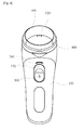
- Figure 1 is a perspective view illustrating a cosmetic container with an ion introduction unit according to a preferred embodiment of the present invention
- Figure 2 is a front view illustrating a cosmetic container with an ion introduction unit according to a preferred embodiment of the present invention
- Figure 3 is a side cross sectional view illustrating a cosmetic container with an ion introduction unit according to a preferred embodiment of the present invention.
- Figure 4 and 5 are a view of an operation state of a cosmetic container with an ion introduction unit according to a preferred embodiment of the present invention.
- Figure 1 is a perspective view illustrating a cosmetic container with an ion introduction unit according to a preferred embodiment of the present invention
- Figure 2 is a front view illustrating a cosmetic container with an ion introduction unit according to a preferred embodiment of the present invention
- Figure 3 is a side cross sectional view illustrating a cosmetic container with an ion introduction unit according to a preferred embodiment of the present invention.
- the cosmetic container with an ion introduction unit comprises a lower casing 100, a cosmetic storing container 200, a button 300, an upper casing 400, and an ion introduction unit 500.
- a slippery prevention part 120 There are further provided a slippery prevention part 120, a power supply battery 520, a wireless charger 530, and a LED display unit 540.
- the lower casing 100 stores cosmetics and is formed in a streamline shape for an easier holding by a user.
- a button engaging hole 110 passes through one side of the lower casing 100. Since a button 300, which will be described later, is engaged to the button engaging hole 110, the user can use cosmetics by pressing upwards the button 300 with a thumb while holding the lower casing 100 with a hand. At this time, the button engaging hole 110 passes through at a certain height at one side of the lower casing 100, which facilities the button 300 to move vertically.
- a slippery prevention part 120 has protrusions and is installed at one side surface of the lower casing 100. When the user holds the lower casing 100, the lower casing 100 does not well escape from the user's hand with the aid of the same. It is preferred that the slippery prevention part 120 is installed at the other side surface of the button engaging hole 110 to be placed at the finger portions except for the thumb when the user holds the lower casing 100 and is made of tough materials so as to have a lot of friction force.
- the cosmetic storing container 200 is installed in the interior of the lower casing 100 and stores cosmetics therein. When the button 300 is pressed upwards, cosmetics are discharged. The cosmetic storing container 200 is assembled or disassembled from the lower casing 100. When the cosmetics run out, it can be replaced with a new container for thereby refilling the cosmetics.
- the cosmetic storing container 200 comprises a housing 210, a fixture 220, a piston rod 230, a recovery spring 240 and a dispenser 250.
- the housing 210 is shaped in a container shape to store cosmetics therein.
- the cosmetic storing container 200 stores various cosmetics (eye cream, canceller, lip gloss, etc.).
- the cosmetic storing container 200 is generally made of a synthetic resin of plastic, with a piston 211 being installed at a lower side of the same. Since the piston 211 is contracted by as much height as the volume of the used cosmetics as the user uses cosmetics, the piston 2100 protruded beyond the top of the housing 210. The cosmetics remain always on the top of the housing 210 until the cosmetics run out.
- the piston 211 is made of flexible material, and the portion where the cosmetics are stored is air-tightly separated in the interior of the housing 210, so it can be possible for the portion where cosmetics are stored, to be in a vacuum state.
- the fixture 220 is fixed to the upper side of the housing 210, with an insertion hole 221 being formed at the center portion in a vertical direction.
- the fixture 220 seals the cosmetics stored in the interior of the housing 210, and the piston rod 230, which will be described later, is inserted into the insertion hole 221.
- the piston rod 230 is inserted into the insertion hole 221, and the diameter of the center portion of the piston rod 230 is the same as the diameter of the insertion hole 221 so that the cosmetics stored in the housing 210 do not discharge to the outside.
- the diameter of the upper side of the piston rod 230 is larger than the diameter of the insertion hole 221, so that the piston rod 230 is prevented from inserting into the insertion hole 221 and escaping into the interior of the housing 210.
- the recovery spring 240 is installed between the fixture 220 and the piston rod 230.
- the recovery spring 240 is to recover the fixture 220 to its original position with the aid of an elastic recovery force of the spring after the fixture 220 is pressed upwards by means of the button 230 which will be described later.
- the dispenser 250 has a diameter larger than the insertion hole 221 and is inserted into a lower side of the piston rod 230.
- the dispenser 250 prevents the piston rod 230 from escaping toward the upper side of the insertion hole 221.
- a check valve 251 is installed at a lower side of the dispenser 250. When pressure is applied to the check valve 251, the cosmetics are inputted into the interior of the dispenser 250. The inputted cosmetics are discharged to the outside via the cosmetic discharge port 410 through the center portion of the piston rod 230.
- the button 300 is installed at a lower side of the fixture 220, with one side of the same being installed at the button engaging hole 110.
- the button 300 surrounds the outer sides of the housing 210 and is installed at a lower side of the fixture 220.
- the housing 210 and the fixture 220 concurrently move upward.
- the button 300, the housing 210 and the fixture 220 move downwards by means of an elastic recovery force of the recovery spring 240.
- the check valve 250 opens by the pressure of the cosmetics, and the cosmetics fill into the inner space of the dispenser 250.
- the upper casing 400 is installed at an upper side of the lower casing 100, and the cosmetics are discharged via the cosmetic discharge port 410.
- the cosmetic discharge port 410 passes through the upper side of the piston rod 230 and receives the cosmetics from the upper side of the piston rod 230 and discharges the same to the outside.
- the upper casing 400 is installed at an upper side of the lower casing 100 in an opening and closing structure.
- the user opens the upper casing 400 and easily exchanges the cosmetic storing container 200 with new one.
- the ion introduction unit 500 is installed at an upper side of the upper casing 400 for performing an ion introduction function by emitting small electric currents.
- the ion introduction part 500 operates by receiving power from the power switch 510 installed at one side of the lower casing 100. Since the ion introduction unit 500 emits small electric currents, electric repulsive force is generated from the electric charges of the cosmetics and the skin supplement products, which helps penetrate the cosmetics or skin supplement products into the deeper portions of a user's skin.
- the ion introduction unit 500 is easy to use since the user presses the button 300 upwards and instantly uses the cosmetics from the cosmetic discharge port 410, while maximizing the effects that the cosmetics penetrate into the user's skin, which are the major features of the present invention.
- the ion introduction unit 500 might be configured to be electrically charged in a wireless method by installing a power supply battery 520 and a wireless charger 530 at one side of the lower casing 100 for thereby supplying electric power to the ion introduction unit 500.
- an external power adaptor (not shown) is connected to one side of the ion introduction unit 500.
- the power supply battery 520 and the wireless charger 530 are installed in the interior of the lower casing 100, so the user can easily use the ion introduction unit 500 wirelessly without installing the external power adaptor (not shown).
- the wireless charger 530 receives electric power from the outside and charges external power to the power supply battery 520, so the user can easily use the ion introduction unit 500 anywhere.
- a LED display part 540 is installed at one side of the lower casing 100 for thereby displaying the charging state of the ion introduction unit 500.
- the LED display part 540 is connected to one side of the power supply battery 520 for thereby receiving electric power from the same. It is preferred that the LED display part 540 is designed to change its emission color depending on the charging level of the same, so that the user can easily recognize the timing of charge.
Landscapes
- Cosmetics (AREA)
- Electrotherapy Devices (AREA)
Abstract
The cosmetic container with an ion introduction unit is disclosed, which cosmetic container comprises a streamline shaped lower casing which has a button engaging hole formed at one side and passing through; a cosmetic storing container which includes a housing which is installed in the interior of the lower casing and stores cosmetics therein, with a piston being installed at a lower side of the same; a fixture which is inserted into an upper side of the housing and has an insertion hole passing through the center of the same; a piston rod, of which center portion is vertically passed through, with a lower end of the same being inserted into the insertion hole, with an upper portion of the same having a diameter larger than the insertion hole; a recovery spring which is installed between the fixture and the upper side of the piston rod; and a dispenser which has a diameter larger than the insertion hole and is inserted into a lower side of the piston rod and has a check valve at its lower side while being opened and closed by means of a pressure of cosmetics; a button which is installed at a lower side of the fixture and of which one side is inserted into the button engaging hole; an upper casing which is installed at an upper side of the lower casing and has a passing-through cosmetic discharge port connected with an upper side of the piston rod for thereby discharging cosmetics; and an ion introduction unit which is installed at an upper side of the upper casing and penetrates cosmetics into a skin with the aid of potential difference, with a power switch being installed at one side of the lower casing.
Description
- The present invention relates to a cosmetic container with an ion introduction unit, and in particular to a cosmetic container with an ion introduction unit in which a cosmetic casing and an ion introduction unit are formed in a singular structure and cosmetics can be applied on a skin together with ions.
- A lower casing is made in a streamline shape, which results in an easier holding of the cosmetic container.
- A person uses an ion introduction unit in order to apply a cosmetic or a skin supplement product into a deeper portion of a skin when the user applies a certain cosmetic, a skin supplement product or something in order to effectively care a skin, in particular, a face skin. The ion introduction unit emits small electric currents which helps apply a cosmetic product or a skin supplement product into a deeper portion of a skin with the aid of an electric repulsive force of electric charges. The ion introduction unit is widely used for its excellent effects.
- However, the conventional ion introduction unit has a problem that cosmetics do not well discharge. So, the user of the conventional ion introduction unit has to directly apply a cosmetics or a skin supplement product with a hand, and the user uses the ion introduction unit separately from the use of cosmetics. The user is needed to remove part of the cosmetics applied on the hand when using the ion introduction unit, which causes a lot of inconveniences when in use and results in an increase of time needed for makeup.
- Since the conventional ion introduction unit is simply made in a cylindrical shape at a portion where a user usually holds, a user feels uneasy when he holds the ion introduction unit with hands.
- Accordingly, it is an object of the present invention to overcome the above problems and to provide a cosmetic container with an ion introduction unit in which a cosmetic casing and an ion introduction unit are formed in a singular structure and cosmetics can be directly applied on a skin together with ions.
- In the present invention, a lower casing is made in a streamline shape, which results in an easier holding of the cosmetic container.
- To achieve the above objects, there is provided a cosmetic container with an ion introduction unit which comprises a streamline shaped lower casing which has a button engaging hole formed at one side and passing through; a cosmetic storing container which includes a housing which is installed in the interior of the lower casing and stores cosmetics therein, with a piston being installed at a lower side of the same; a fixture which is inserted into an upper side of the housing and has an insertion hole passing through the center of the same; a piston rod, of which center portion is vertically passed through, with a lower end of the same being inserted into the insertion hole, with an upper portion of the same having a diameter larger than the insertion hole; a recovery spring which is installed between the fixture and the upper side of the piston rod; and a dispenser which has a diameter larger than the insertion hole and is inserted into a lower side of the piston rod and has a check valve at its lower side while being opened and closed by means of a pressure of cosmetics; a button which is installed at a lower side of the fixture and of which one side is inserted into the button engaging hole; an upper casing which is installed at an upper side of the lower casing and has a passing-through cosmetic discharge port connected with an upper side of the piston rod for thereby discharging cosmetics; and an ion introduction unit which is installed at an upper side of the upper casing and penetrates cosmetics into a skin with the aid of potential difference, with a power switch being installed at one side of the lower casing.
- The lower casing comprises a slippery prevention part made of a rough material and formed at one side of the same and having protrusions on its surface.
- The ion introduction unit comprises a power supply battery which is installed in the interior of the lower casing and supplies power to the ion introduction part; and a wireless charger which is installed in the interior of the lower casing and charges the power supply battery by receiving external electric power.
- The ion introduction unit comprises a Light Emitting Diode (LED) display part which is installed at one side of the lower casing and displays the charging state of the ion introduction unit.
- According to the present invention, a cosmetic casing and an ion introduction unit are formed in a singular structure and cosmetics can be directly applied on a skin advantageously together with ions.
- A lower casing is made in a streamline shape, which results in an easier holding of the cosmetic container.
- The present invention will become better understood with reference to the accompanying drawings which are given only by way of illustration and thus are not limitative of the present invention, wherein;
-
Figure 1 is a perspective view illustrating a cosmetic container with an ion introduction unit according to a preferred embodiment of the present invention; -
Figure 2 is a front view illustrating a cosmetic container with an ion introduction unit according to a preferred embodiment of the present invention; -
Figure 3 is a side cross sectional view illustrating a cosmetic container with an ion introduction unit according to a preferred embodiment of the present invention; and -
Figure 4 and5 are a view of an operation state of a cosmetic container with an ion introduction unit according to a preferred embodiment of the present invention. - The preferred embodiments of the present invention will be described with reference to the accompanying drawings. The same elements shown in each drawing will be given the same reference numerals.
-
Figure 1 is a perspective view illustrating a cosmetic container with an ion introduction unit according to a preferred embodiment of the present invention, andFigure 2 is a front view illustrating a cosmetic container with an ion introduction unit according to a preferred embodiment of the present invention, andFigure 3 is a side cross sectional view illustrating a cosmetic container with an ion introduction unit according to a preferred embodiment of the present invention. - As shown in
Figures 1 to 3 , the cosmetic container with an ion introduction unit according to a preferred embodiment of the present invention comprises alower casing 100, acosmetic storing container 200, abutton 300, anupper casing 400, and anion introduction unit 500. There are further provided aslippery prevention part 120, apower supply battery 520, awireless charger 530, and aLED display unit 540. - The
lower casing 100 stores cosmetics and is formed in a streamline shape for an easier holding by a user. Abutton engaging hole 110 passes through one side of thelower casing 100. Since abutton 300, which will be described later, is engaged to thebutton engaging hole 110, the user can use cosmetics by pressing upwards thebutton 300 with a thumb while holding thelower casing 100 with a hand. At this time, thebutton engaging hole 110 passes through at a certain height at one side of thelower casing 100, which facilities thebutton 300 to move vertically. - A
slippery prevention part 120 has protrusions and is installed at one side surface of thelower casing 100. When the user holds thelower casing 100, thelower casing 100 does not well escape from the user's hand with the aid of the same. It is preferred that theslippery prevention part 120 is installed at the other side surface of thebutton engaging hole 110 to be placed at the finger portions except for the thumb when the user holds thelower casing 100 and is made of tough materials so as to have a lot of friction force. - The
cosmetic storing container 200 is installed in the interior of thelower casing 100 and stores cosmetics therein. When thebutton 300 is pressed upwards, cosmetics are discharged. Thecosmetic storing container 200 is assembled or disassembled from thelower casing 100. When the cosmetics run out, it can be replaced with a new container for thereby refilling the cosmetics. Thecosmetic storing container 200 comprises ahousing 210, afixture 220, apiston rod 230, arecovery spring 240 and adispenser 250. - The
housing 210 is shaped in a container shape to store cosmetics therein. Thecosmetic storing container 200 stores various cosmetics (eye cream, canceller, lip gloss, etc.). Thecosmetic storing container 200 is generally made of a synthetic resin of plastic, with apiston 211 being installed at a lower side of the same. Since thepiston 211 is contracted by as much height as the volume of the used cosmetics as the user uses cosmetics, the piston 2100 protruded beyond the top of thehousing 210. The cosmetics remain always on the top of thehousing 210 until the cosmetics run out. Thepiston 211 is made of flexible material, and the portion where the cosmetics are stored is air-tightly separated in the interior of thehousing 210, so it can be possible for the portion where cosmetics are stored, to be in a vacuum state. - The
fixture 220 is fixed to the upper side of thehousing 210, with aninsertion hole 221 being formed at the center portion in a vertical direction. Thefixture 220 seals the cosmetics stored in the interior of thehousing 210, and thepiston rod 230, which will be described later, is inserted into theinsertion hole 221. - The
piston rod 230 is inserted into theinsertion hole 221, and the diameter of the center portion of thepiston rod 230 is the same as the diameter of theinsertion hole 221 so that the cosmetics stored in thehousing 210 do not discharge to the outside. The diameter of the upper side of thepiston rod 230 is larger than the diameter of theinsertion hole 221, so that thepiston rod 230 is prevented from inserting into theinsertion hole 221 and escaping into the interior of thehousing 210. - The
recovery spring 240 is installed between thefixture 220 and thepiston rod 230. Therecovery spring 240 is to recover thefixture 220 to its original position with the aid of an elastic recovery force of the spring after thefixture 220 is pressed upwards by means of thebutton 230 which will be described later. - The
dispenser 250 has a diameter larger than theinsertion hole 221 and is inserted into a lower side of thepiston rod 230. Thedispenser 250 prevents thepiston rod 230 from escaping toward the upper side of theinsertion hole 221. Acheck valve 251 is installed at a lower side of thedispenser 250. When pressure is applied to thecheck valve 251, the cosmetics are inputted into the interior of thedispenser 250. The inputted cosmetics are discharged to the outside via thecosmetic discharge port 410 through the center portion of thepiston rod 230. - The
button 300 is installed at a lower side of thefixture 220, with one side of the same being installed at thebutton engaging hole 110. Thebutton 300 surrounds the outer sides of thehousing 210 and is installed at a lower side of thefixture 220. When the user pressures thebutton 300 upwards, thehousing 210 and thefixture 220 concurrently move upward. As shown inFigure 4 , since the upper side of thepiston rod 230 is fixed by means of theupper casing 400, the inner space of thedispenser 250 is compressed, which results in discharging cosmetics. As shown inFigure 5 , thebutton 300, thehousing 210 and thefixture 220 move downwards by means of an elastic recovery force of therecovery spring 240. At this time, since the inner space of thedispenser 250 increases, thecheck valve 250 opens by the pressure of the cosmetics, and the cosmetics fill into the inner space of thedispenser 250. - The
upper casing 400 is installed at an upper side of thelower casing 100, and the cosmetics are discharged via thecosmetic discharge port 410. Thecosmetic discharge port 410 passes through the upper side of thepiston rod 230 and receives the cosmetics from the upper side of thepiston rod 230 and discharges the same to the outside. - The
upper casing 400 is installed at an upper side of thelower casing 100 in an opening and closing structure. When the cosmetics stored in thecosmetic storing container 200 runs out by a user, the user opens theupper casing 400 and easily exchanges thecosmetic storing container 200 with new one. - The
ion introduction unit 500 is installed at an upper side of theupper casing 400 for performing an ion introduction function by emitting small electric currents. Theion introduction part 500 operates by receiving power from thepower switch 510 installed at one side of thelower casing 100. Since theion introduction unit 500 emits small electric currents, electric repulsive force is generated from the electric charges of the cosmetics and the skin supplement products, which helps penetrate the cosmetics or skin supplement products into the deeper portions of a user's skin. Theion introduction unit 500 is easy to use since the user presses thebutton 300 upwards and instantly uses the cosmetics from thecosmetic discharge port 410, while maximizing the effects that the cosmetics penetrate into the user's skin, which are the major features of the present invention. - The
ion introduction unit 500 might be configured to be electrically charged in a wireless method by installing apower supply battery 520 and awireless charger 530 at one side of thelower casing 100 for thereby supplying electric power to theion introduction unit 500. When introducing ions from theion introduction unit 500, it is preferred that an external power adaptor (not shown) is connected to one side of theion introduction unit 500. Thepower supply battery 520 and thewireless charger 530 are installed in the interior of thelower casing 100, so the user can easily use theion introduction unit 500 wirelessly without installing the external power adaptor (not shown). Thewireless charger 530 receives electric power from the outside and charges external power to thepower supply battery 520, so the user can easily use theion introduction unit 500 anywhere. - A
LED display part 540 is installed at one side of thelower casing 100 for thereby displaying the charging state of theion introduction unit 500. TheLED display part 540 is connected to one side of thepower supply battery 520 for thereby receiving electric power from the same. It is preferred that theLED display part 540 is designed to change its emission color depending on the charging level of the same, so that the user can easily recognize the timing of charge. - As the present invention may be embodied in several forms without departing from the spirit or essential characteristics thereof, it should also be understood that the above-described examples are not limited by any of the details of the foregoing description, unless otherwise specified, but rather should be construed broadly within its spirit and scope as defined in the appended claims, and therefore all changes and modifications that fall within the meets and bounds of the claims, or equivalences of such meets and bounds are therefore intended to be embraced by the appended claims.
Claims (4)
- A cosmetic container with an ion introduction unit, comprising:a streamline shaped lower casing which has a button engaging hole formed at one side and passing through;a cosmetic storing container which includes:a housing which is installed in the interior of the lower casing and stores cosmetics therein, with a piston being installed at a lower side of the same;a fixture which is inserted into an upper side of the housing and has an insertion hole passing through the center of the same;a piston rod, of which center portion is vertically passed through, with a lower end of the same being inserted into the insertion hole, with an upper portion of the same having a diameter larger than the insertion hole;a recovery spring which is installed between the fixture and the upper side of the piston rod; anda dispenser which has a diameter larger than the insertion hole and is inserted into a lower side of the piston rod and has a check valve at its lower side while being opened and closed by means of a pressure of cosmetics;a button which is installed at a lower side of the fixture and of which one side is inserted into the button engaging hole;an upper casing which is installed at an upper side of the lower casing and has a passing-through cosmetic discharge port connected with an upper side of the piston rod for thereby discharging cosmetics; andan ion introduction unit which is installed at an upper side of the upper casing and penetrates cosmetics into a skin with the aid of potential difference, with a power switch being installed at one side of the lower casing.
- The container according to claim 1, wherein said lower casing comprises a slippery prevention part formed at one side of the same and having protrusions on its surface.
- The container according to claim 1, wherein said ion introduction unit comprises:a power supply battery which is installed in the interior of the lower casing and supplies power to the ion introduction part; anda wireless charger which is installed in the interior of the lower casing and charges the power supply battery by receiving external electric power.
- The container according to claim 1, wherein said ion introduction unit comprises a Light Emitting Diode (LED) display part which is installed at one side of the lower casing and displays the charging state of the ion introduction unit.
Applications Claiming Priority (2)
| Application Number | Priority Date | Filing Date | Title |
|---|---|---|---|
| KR1020080093653A KR100900788B1 (en) | 2008-09-24 | 2008-09-24 | Cosmetic container with iontophoretic device |
| PCT/KR2009/001986 WO2010035930A1 (en) | 2008-09-24 | 2009-04-16 | Cosmetic container with iontophoresis device |
Publications (1)
| Publication Number | Publication Date |
|---|---|
| EP2332442A1 true EP2332442A1 (en) | 2011-06-15 |
Family
ID=40982216
Family Applications (1)
| Application Number | Title | Priority Date | Filing Date |
|---|---|---|---|
| EP09816323A Withdrawn EP2332442A1 (en) | 2008-09-24 | 2009-04-16 | Cosmetic container with iontophoresis device |
Country Status (6)
| Country | Link |
|---|---|
| US (1) | US20110170934A1 (en) |
| EP (1) | EP2332442A1 (en) |
| JP (1) | JP5495139B2 (en) |
| KR (1) | KR100900788B1 (en) |
| CN (1) | CN102176843B (en) |
| WO (1) | WO2010035930A1 (en) |
Cited By (1)
| Publication number | Priority date | Publication date | Assignee | Title |
|---|---|---|---|---|
| WO2015003762A1 (en) * | 2013-07-09 | 2015-01-15 | Gerhard Brugger | Metering dispenser for discharging an in particular pasty or viscous material, such as cosmetic cream, adhesive, and the like |
Families Citing this family (14)
| Publication number | Priority date | Publication date | Assignee | Title |
|---|---|---|---|---|
| KR100938921B1 (en) | 2009-05-29 | 2010-01-27 | (주)연우 | A cosmetics case having ion injector |
| KR101109217B1 (en) | 2009-10-20 | 2012-01-30 | 이용식 | Vessel with iontophoresis device |
| KR101177177B1 (en) * | 2009-11-06 | 2012-08-24 | 이용식 | Cosmetic container with fine vibration temperature input function |
| US9522267B2 (en) * | 2012-02-08 | 2016-12-20 | Derma Dream Group Ltd | Transdermal delivery device |
| KR101571444B1 (en) | 2013-10-07 | 2015-11-24 | (주)연우 | Ion injector using a mask-pack |
| DE102013018937A1 (en) * | 2013-11-12 | 2015-05-28 | Gerhard Brugger | Dosing dispenser for the discharge of a particular pasty or viscous material, such as cosmetics creams, adhesives and the like |
| FR3020748B1 (en) * | 2014-05-07 | 2020-10-30 | Aptar France Sas | FLUID PRODUCT DISTRIBUTION AND APPLICATION KIT |
| KR101567027B1 (en) | 2015-05-14 | 2015-11-13 | (주)하배런메디엔뷰티 | Ample galvanic assembly |
| EP3372273A4 (en) * | 2015-11-02 | 2019-07-31 | Shiseido Company, Ltd. | Beauty and health device and cartridge |
| FR3045299B1 (en) * | 2015-12-17 | 2018-01-26 | Seb S.A. | APPARATUS FOR TREATING HUMAN KERATINIC MATERIALS |
| KR101661240B1 (en) * | 2016-03-15 | 2016-09-30 | (주)하배런메디엔뷰티 | Galvanic beauty treatment device |
| KR102505417B1 (en) * | 2017-11-03 | 2023-03-03 | 엘지전자 주식회사 | Skin care device |
| KR102053615B1 (en) * | 2018-07-11 | 2019-12-09 | 안동대학교 산학협력단 | Bottle and apparatus module for displaying electricity generation of electricity generation cosmetics |
| CN117652766A (en) | 2022-08-26 | 2024-03-08 | 洽兴包装工业(中国)有限公司 | Side push makeup pen |
Family Cites Families (7)
| Publication number | Priority date | Publication date | Assignee | Title |
|---|---|---|---|---|
| KR0124496B1 (en) * | 1993-02-19 | 1997-11-26 | 김광호 | Ozone-derived Skin Sterilizer |
| JP2667379B2 (en) * | 1995-03-31 | 1997-10-27 | 株式会社ジャパンギャルズ | Iontophoresis device |
| KR19980056332U (en) * | 1997-01-11 | 1998-10-15 | 구재림 | Ion pulser |
| DE19729516C2 (en) * | 1997-07-10 | 1999-04-22 | Georg Wiegner | Pump for the dosed discharge of liquid, gel-like or viscous substances |
| KR200420454Y1 (en) | 2006-04-17 | 2006-07-04 | 정정한 | Hair brush for applying hair nutrient |
| KR100655450B1 (en) | 2006-04-17 | 2006-12-08 | 주식회사 일우정밀 | Blown ion introducer |
| US20100191171A1 (en) * | 2006-08-30 | 2010-07-29 | Lg Household & Health Care Ltd. | Iontophoresis device |
-
2008
- 2008-09-24 KR KR1020080093653A patent/KR100900788B1/en not_active Expired - Fee Related
-
2009
- 2009-04-16 WO PCT/KR2009/001986 patent/WO2010035930A1/en not_active Ceased
- 2009-04-16 US US13/120,637 patent/US20110170934A1/en not_active Abandoned
- 2009-04-16 EP EP09816323A patent/EP2332442A1/en not_active Withdrawn
- 2009-04-16 CN CN2009801369877A patent/CN102176843B/en not_active Expired - Fee Related
- 2009-04-16 JP JP2011527733A patent/JP5495139B2/en not_active Expired - Fee Related
Non-Patent Citations (1)
| Title |
|---|
| See references of WO2010035930A1 * |
Cited By (2)
| Publication number | Priority date | Publication date | Assignee | Title |
|---|---|---|---|---|
| WO2015003762A1 (en) * | 2013-07-09 | 2015-01-15 | Gerhard Brugger | Metering dispenser for discharging an in particular pasty or viscous material, such as cosmetic cream, adhesive, and the like |
| US9770736B2 (en) | 2013-07-09 | 2017-09-26 | Gerhard Brugger | Metering dispenser for discharging an in particular pasty or viscous material, such as cosmetic cream, adhesive, and the like |
Also Published As
| Publication number | Publication date |
|---|---|
| KR100900788B1 (en) | 2009-06-02 |
| JP5495139B2 (en) | 2014-05-21 |
| JP2012511939A (en) | 2012-05-31 |
| CN102176843B (en) | 2013-08-14 |
| US20110170934A1 (en) | 2011-07-14 |
| WO2010035930A1 (en) | 2010-04-01 |
| CN102176843A (en) | 2011-09-07 |
Similar Documents
| Publication | Publication Date | Title |
|---|---|---|
| US20110170934A1 (en) | Cosmetic container with iontophoresis device | |
| EP2407049A2 (en) | Cosmetics container for mixing different contents before use | |
| EP2356920A1 (en) | Pencil-shaped cosmetic container | |
| US8757516B2 (en) | Cosmetic airbrush system | |
| KR200452889Y1 (en) | Cosmetic applicator | |
| KR101387624B1 (en) | Lip-gloss cosmetic container of button type operate pump silicone material | |
| KR20150132144A (en) | Mechanically driven, sonic toothbrush and water flosser | |
| EP3262973B1 (en) | Vertically pressed compact container provided with pouch container | |
| KR200464876Y1 (en) | Pump type massage container with vibration means | |
| KR102328230B1 (en) | Personnal care apparatus | |
| KR20180127977A (en) | Compressible dispensers for liquid products, especially cosmetic liquid products such as creams | |
| JP2023021968A (en) | Set consisting of pump dispenser and evaluation unit | |
| KR20130101176A (en) | Spuit model cosmetic container of button type | |
| KR102064062B1 (en) | Pump type liquid sealed container | |
| KR101071101B1 (en) | The cosmetic case | |
| KR101323067B1 (en) | Rechangeable cosmetic rechangeable system | |
| KR101617528B1 (en) | Cosmetic device | |
| GB2517219A (en) | An electric toothbrush | |
| KR200482020Y1 (en) | Eyelashes Curler including Change of Color and Shape | |
| KR101673396B1 (en) | Container having a changeable body frame | |
| KR20150047999A (en) | personal mobile accessory device for self-defense |
Legal Events
| Date | Code | Title | Description |
|---|---|---|---|
| PUAI | Public reference made under article 153(3) epc to a published international application that has entered the european phase |
Free format text: ORIGINAL CODE: 0009012 |
|
| 17P | Request for examination filed |
Effective date: 20110329 |
|
| AK | Designated contracting states |
Kind code of ref document: A1 Designated state(s): AT BE BG CH CY CZ DE DK EE ES FI FR GB GR HR HU IE IS IT LI LT LU LV MC MK MT NL NO PL PT RO SE SI SK TR |
|
| AX | Request for extension of the european patent |
Extension state: AL BA RS |
|
| DAX | Request for extension of the european patent (deleted) | ||
| STAA | Information on the status of an ep patent application or granted ep patent |
Free format text: STATUS: THE APPLICATION IS DEEMED TO BE WITHDRAWN |
|
| 18D | Application deemed to be withdrawn |
Effective date: 20141101 |